1. Introduction
Cooling hot electronic chips in an enclosure under natural convection condition is sometimes favorable because of numerous advantages that active cooling technique using blowers cannot achieve, such as noiseless, energy-saving and cost reduction. Handheld projectors, also named pico projectors, which are devices capable of projecting the information displayed on the mobile phone screen onto a larger surface to share with audience are highly demanded and consequently are expected to become a built-in device in every mobile phone in the near future. No matter what type of light source is used for the light engine in a handheld projector, the light engine generates a considerable amount of heat [
1,
2] within the handheld projector. Because maintaining the light engine at a comparatively low temperature is crucial for excellent and stable display quality, to efficiently dissipate the heat from the light engine to the ambient is of great importance.
An isolated surface which excludes the interaction between the airflow induced by adjoining extended surfaces can be considered as the most simplified configuration of a fin array. Numerous heat transfer correlations on the natural convection of an isolated surface with various inclinations in form of
have been proposed [
3,
4,
5,
6,
7,
8]. To some degree, those heat transfer studies on an isolated surface formed the foundation of numerous following studies which investigated various effects on the natural convection heat transfer of a fin array in an infinite, still medium [
9,
10,
11,
12,
13,
14,
15,
16,
17,
18]. The results of those studies revealed that the fin material, fin pattern, and the spacing between fins, as well as the fin thickness affect the thermal performance of the fin array. Because the airflow of free convection is induced by buoyancy, the orientation of the fin array also plays an important role in heat transfer under natural convection condition. In addition, some of those studies proposed empirical correlations which are applicable to predict the heat transfer coefficient and the optimum fin spacing [
13,
14,
16] of a fin array in an infinite, still medium. Milnes et al. [
19,
20] examined the turbulence models to predict the variation of steady-state heat transfer coefficients throughout the Hypervapotron using computational fluid dynamics software. Drikakis et al. [
21] investigated the formation of spurious vortical structures in incompressible flow simulations employing Godunov-type methods.
However, the situation which a fin array is arranged in an enclosure, for example, the handheld projector, is much harsher than the situation stated in the previous paragraph, since the induced airflow for cooling the fin array is restricted by both the openings position and the dimensions of the case, and the clearance between the fin array and the shield in the vicinity as well.
Shyu and Chan [
22] measured the thermal resistance and the temperature distribution of the case surface of handheld projectors possessing a fin array. Three different handheld projector designs having two different types of fin arrays were tested. They also proposed a thermal resistance network of the handheld projectors to investigate the heat transfer coefficient of those combinations based on the measured temperature and thermal resistance. In order to enhance the heat transfer of the handheld projector, Shyu and Tsai [
23] installed a piezoelectric fan that had a Mylar blade vibrating at several specific frequencies at 110 V in the handheld projector. The effects of both the operating frequency of the piezoelectric fan and the heating power on the vibrating amplitude of the piezoelectric fan, and the thermal performance of the handheld projector were investigated in this study.
Since it could be expensive and time-consuming to experimentally investigate various effects of handheld projector on both the airflow field and heat transfer of the handheld projector in detail, this study aims to numerically investigate the thermal characteristics of a 120 mm × 53 mm × 19 mm handheld projector equipped with either a plate-fin array or a pin-fin array under natural convection condition. The effects of both fin dimensions of the plate and pin fin arrays and the openings on the lower case of the projector, and the handheld projector orientation as well, on the airflow in the projector and thermal resistance of the projector will be numerically investigated in this study.
2. Computational Methods and Boundary Conditions
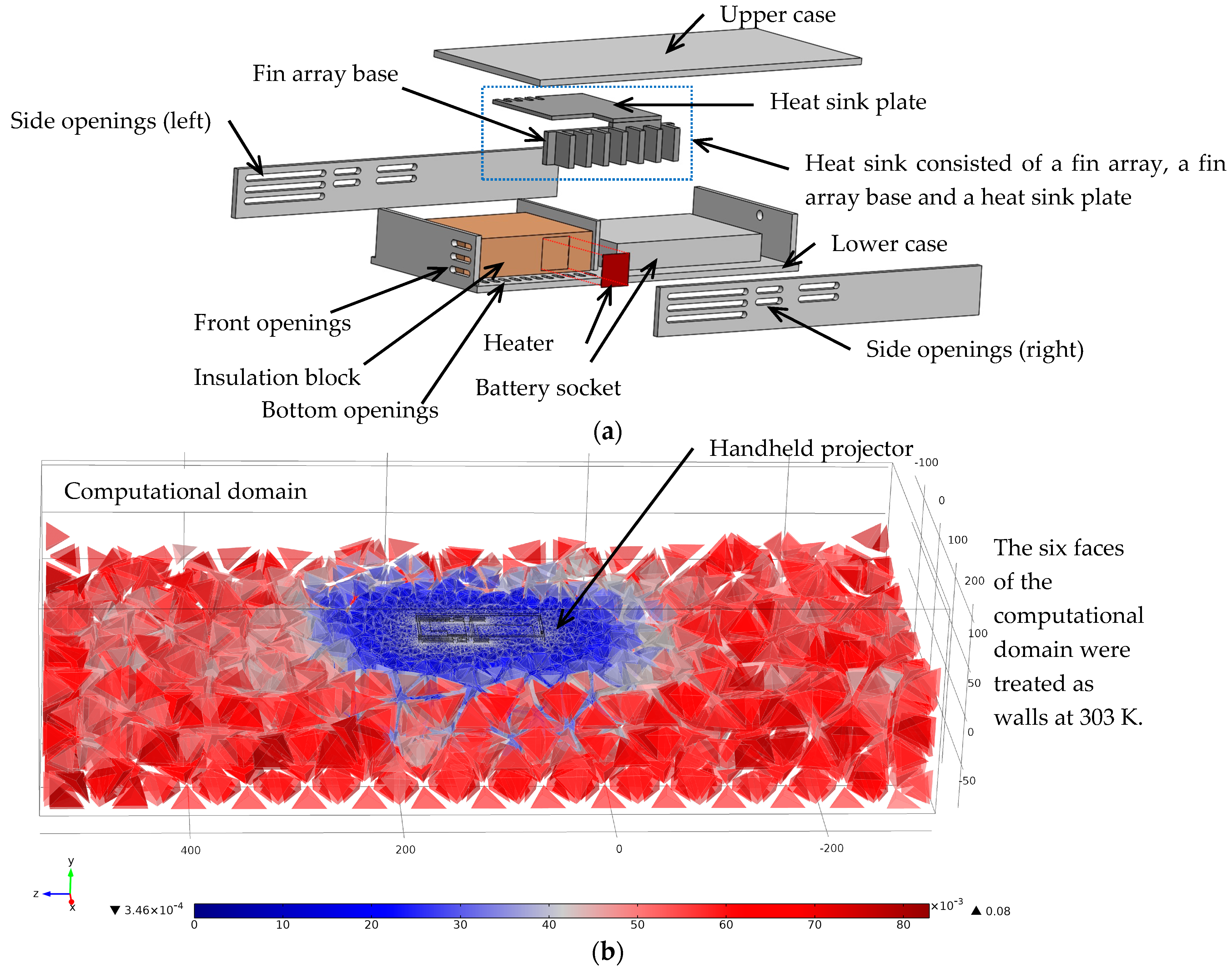
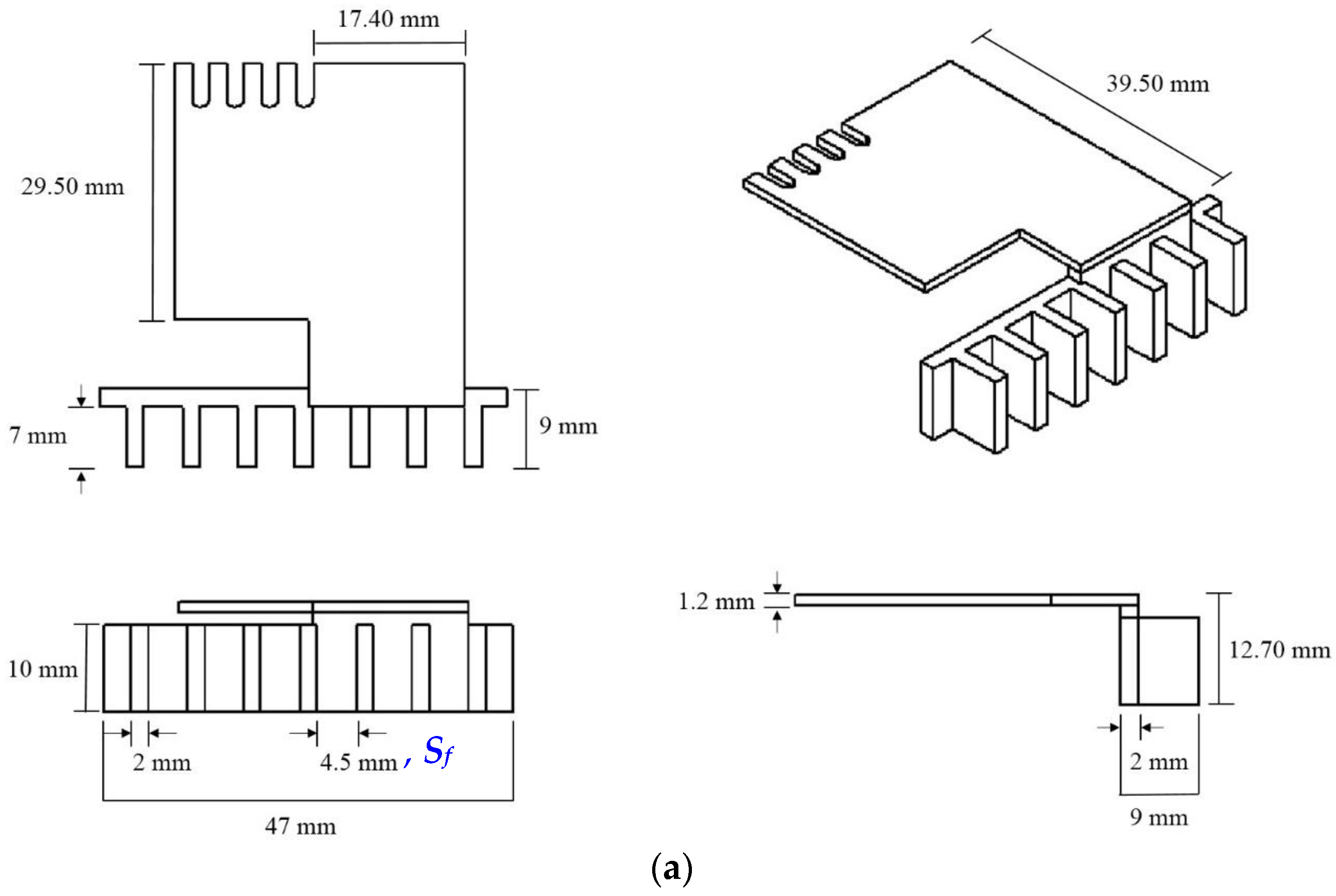
A 120 mm × 53 mm × 19 mm acrylic housing having several openings which is similar to a commercially available handheld projector (DIGI-EYE MP101, Inventec Besta, Taipei, Taiwan) was employed for the present numerical simulation as shown in
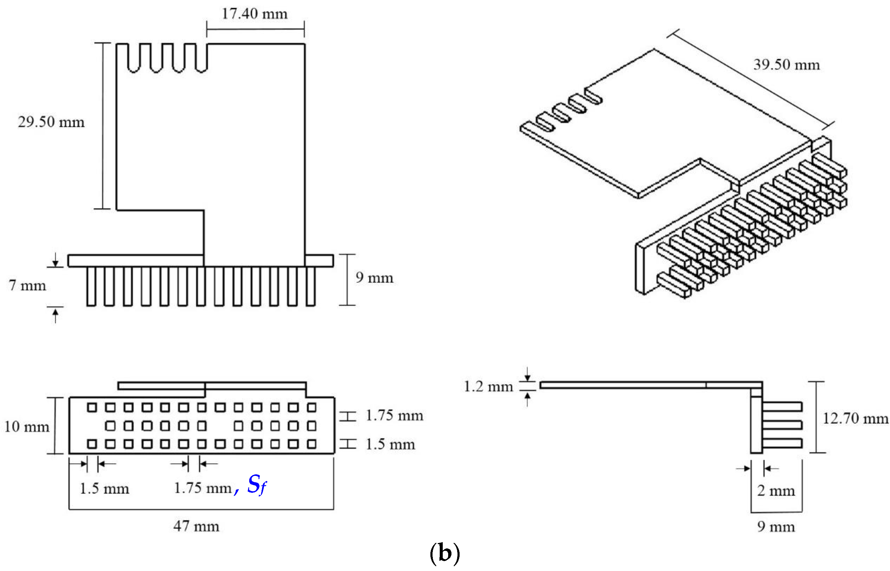
Figure 1a,b. The heat-dissipating light engine in a practical handheld projector was transformed as an assembly of a 10 mm × 10 mm heater and a 47.5 × 33.5 mm × 12 mm insulation block of 0.687 W/m·K in thermal conductivity. A heat sink which is made of Al 6061 and consists of a plate-fin or pin-fin array, a rectangular fin array base and a heat sink plate extending from the fin array base as shown in
Figure 2 tightly attached to the heater. Please refer to [
22,
23] for more detailed description of the dimension and material of all parts in the handheld projector.
The numerical simulation with a handheld projector being centrally located in an 840 mm × 371 mm × 209 mm computational domain as shown in
Figure 1b was performed in this study using commercially available software, COMSOL 5.1. The 3-dimensional numerical simulation was performed based on the following assumptions and boundary conditions:
Both heat transfer and airflow in the simulation are steady.
Airflow is incompressible and laminar.
Radiation heat transfer is negligible.
All properties of air are functions of temperature obtained from COMSOL database.
The thermal conductivity of all solids in the computational domain is constant as listed in
Table 1.
Ambient temperature is constant at 303 K.
All boundaries of the computational domain in
Figure 1b were regarded as walls on which airflow velocity is zero and the temperature is constant at 303 K.
The set of governing equations including continuity equation, momentum equation and energy equation of air flow in the computational domain in three-dimensional Cartesian coordinates are listed as Equations (1)–(3), respectively, subject to the aforementioned assumptions.
where
,
ρ,
,
p,
μ,
T,
Cp, and
k are reference density of air, temperature-dependent density of air, velocity vector of the airflow, pressure, viscosity, temperature, specific heat, and the thermal conductivity of air, respectively. In addition, the following heat diffusion equation was simultaneously employed to compute the temperature distribution in each solid,
where
Q is zero for all solids in the computational domain except the heater which dissipates power of
qs.
Numerical simulation of the governing equations performed by COMSOL is based on finite element method that subdivides the entire computational domain into simpler finite elements, and then uses variational methods to solve the problem by minimizing an associated error function based on Galerkin method of weighted residuals. The governing equations are transformed into a set of linear algebraic equations. These equations were solved using SIMPLE algorithm for the pressure correction processes, and convective and diffusive terms in the governing equations are discretized by upwind and central difference schemes, respectively. The maximum number of iteration was 200, while approximately 170,000 grids were established in the computational domain. The number of grid was tested prior to the numerical study, and it was determined while the most accurate results were obtained based on the comparison between the values obtained from simulation and the measured values. The comparison of thermal resistance and surface temperature distribution are shown in
Figure 3a,b based on the current number of grid. The feature size of the mesh in the computational domain ranged from 0.35 mm to 80 mm as revealed in
Figure 1b. The residual reached 2 × 10
−3~4 × 10
−3 while finishing computation, which correspond to approximately 2 h of computation time per case on a Pentium processor (Intel Xeon E3-1230, 4 cores, 3.2 GHz) computer with 16.0 GB memory.
In order to assure the reliability of the simulation results, the airflow field and the temperature distribution within the computational domain where a horizontally-oriented handheld projector was arranged in the center equipped with either a plate-fin array or a pin-fin array as illustrated
Figure 2 was first computed at several heating powers ranging from 2 W to 7 W, and then those simulated data were compared with the experimental results reported in [
22]. Note that the horizontally-oriented handheld projector having either a plate-fin array possessing 7 7 mm-wide, 10 mm-high and 2 mm-thick rectangular plates as shown in
Figure 2a, or a pin-fin array possessing 13 rows of square pin as shown in
Figure 2b, and 11 bottom openings was considered as the primary case.
Besides, the thermal resistance of the handheld projector from the heater to the ambient was defined as
where
and
are the ambient temperature, 303 K, and the heating power of the heater, respectively, and
is the average temperature over the entire heater surface estimated by
3. Results and Discussion
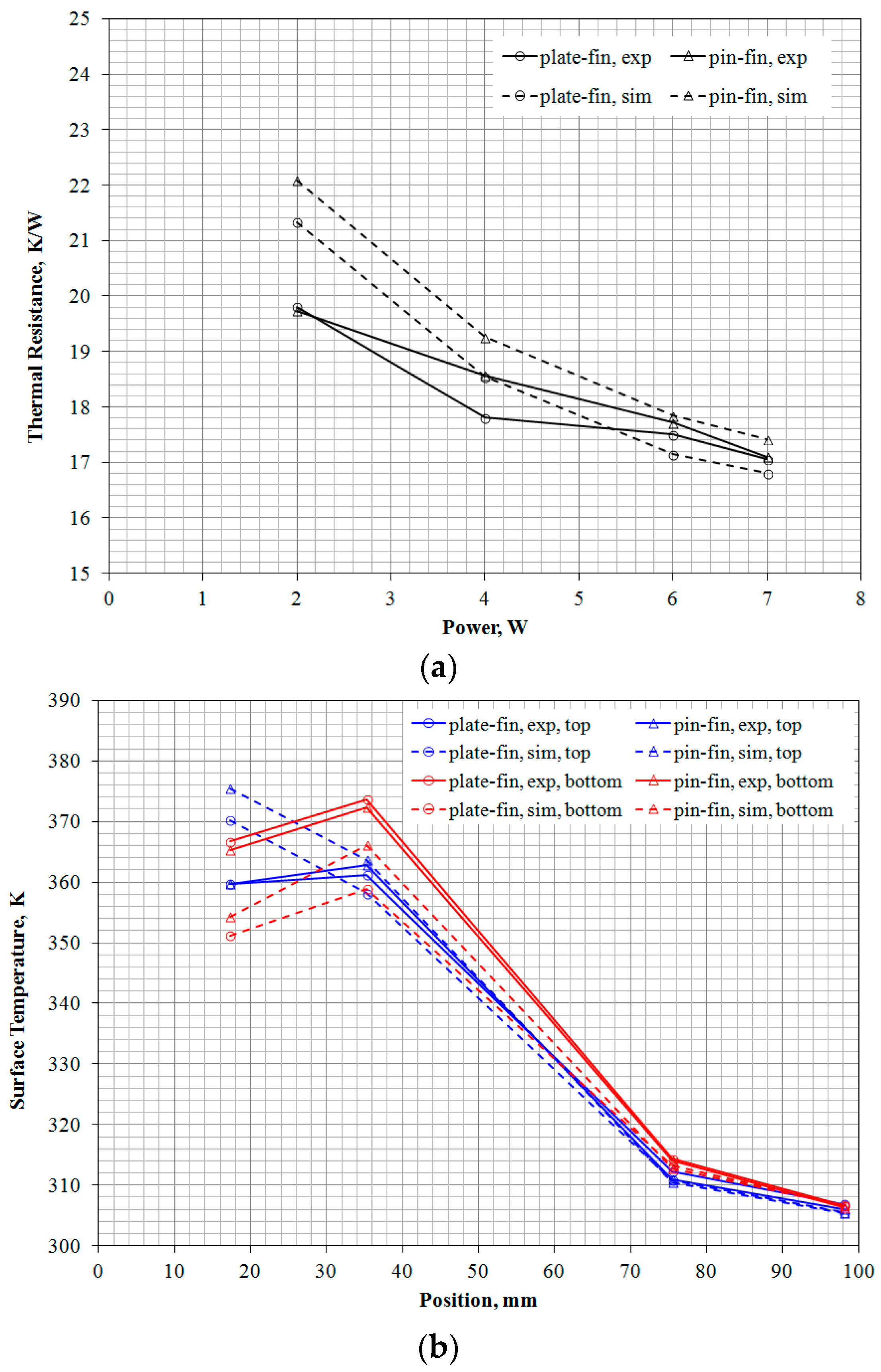
The comparison of both the thermal resistance and the temperature distribution on the handheld projector between the data obtained from the numerical simulation of the primary design and the measured data reported in [
22] are presented in
Figure 3. It can be seen in
Figure 3a that the thermal resistance of the handheld projector equipped with either fin array becomes lower as the heating power increases for both measured results and simulation results. Because the airflow velocity through the pins was less than that through plates in the primary handheld projector, which will be illustrated in
Figure 5, the thermal resistance of the handheld projector having a pin-fin array was higher than the other as shown in
Figure 3a. The maximum deviation of the thermal resistance between the measured values and the simulation data was approximately 10% at 2 W with a pin-fin array. As the heating power increases, the deviation between simulation values and the measured values [
22] becomes insignificant as shown in
Figure 3a. In addition, the comparison of the temperature at four specific positions on both the upper and lower cases of the handheld projector between the measured data [
22] and the present simulation data with a heating power of 7 W is also shown in
Figure 3b. The surface temperature distribution on upper and lower cases are depicted as black and red curves, respectively. The sharp drop in surface temperature between the first two positions and the other two positions was likely because the hot heat sink plate was right beneath the first two measuring points as illustrated in
Figure 1a, the air in the handheld projector heated by the hot heat sink plate could warm up the top surface across the tiny spacing, 1.5 mm, between the heat sink plate and the upper case of the handheld projector via convection and conduction heat transfer. The measured temperature distribution and the simulated values are in reasonable agreement except the first point, which might result from the inaccurate thermal conductivity of the solids listed in
Table 1 and the neglected radiation effect in the simulation.
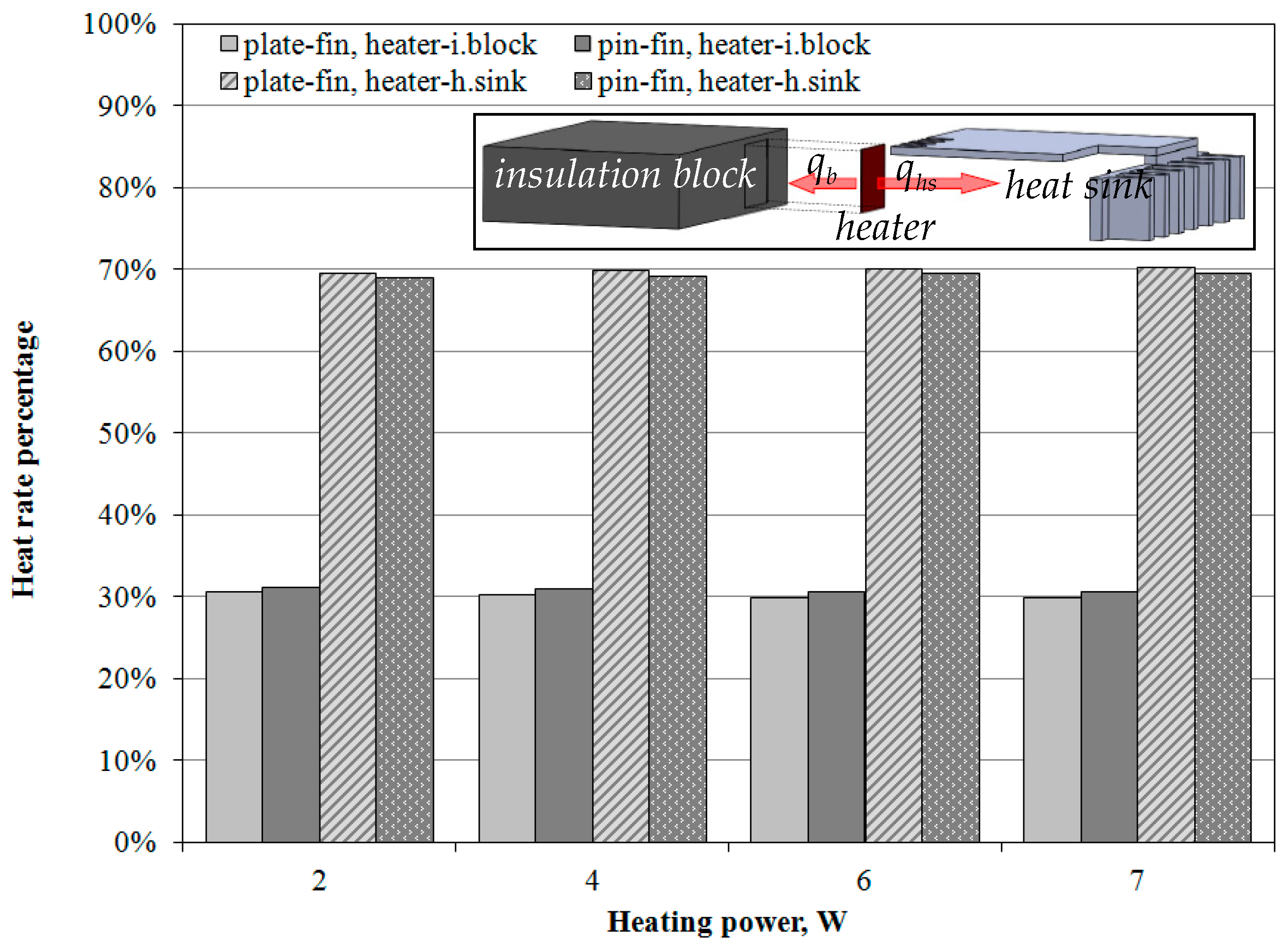
Because the heater was sandwiched between the insulation block and the heat sink as illustrated in
Figure 1a, the heat generated from the heater,
, transferred to the surroundings outside the handheld projector via both the insulation block,
, having thermal conductivity of 0.687 W/m·K, and the aluminum heat sink,
. The heat flow through the former path depends mainly on the conduction across the insulation block and the bottom acrylic case of the handheld projector, while the heat flow through the latter path is associated with the convection and radiation over the heat sink. Since the objective of this study is to investigate the effect of the number of the fin and the case openings on the handheld projector on the thermal resistance of the handheld projector, it is essential to realize the percentage of the heat generated by the heater is dissipated via the heat sink. For the primary case of the handheld projector, the simulation results shows that the percentage of the heating power transferred through the insulation block,
, and the heat sink,
, is approximately 30% and 70%, respectively, regardless of the type of the fin array and the heating power as shown in
Figure 4. The percentage of the heat transfers to surroundings through the heat sink is able to be increased once the arrangement of fin array and case openings is improved.
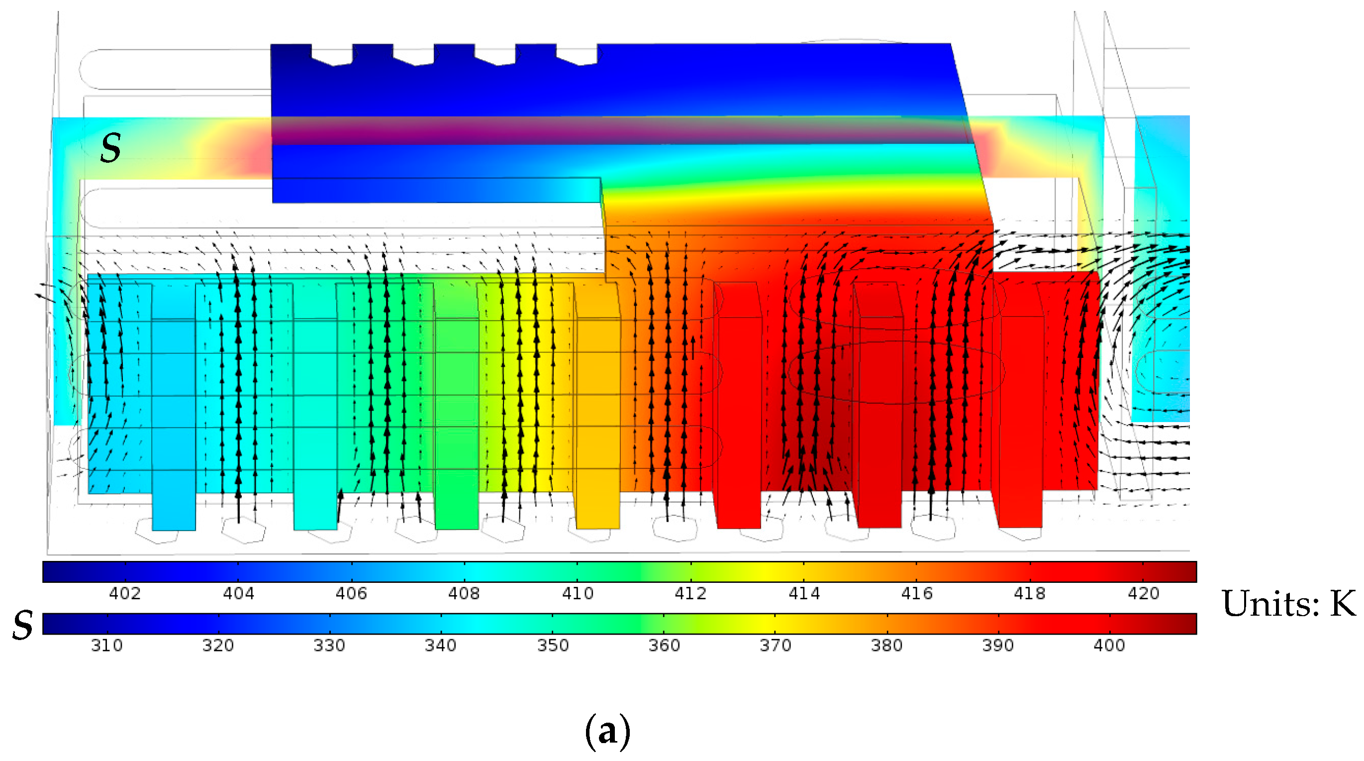
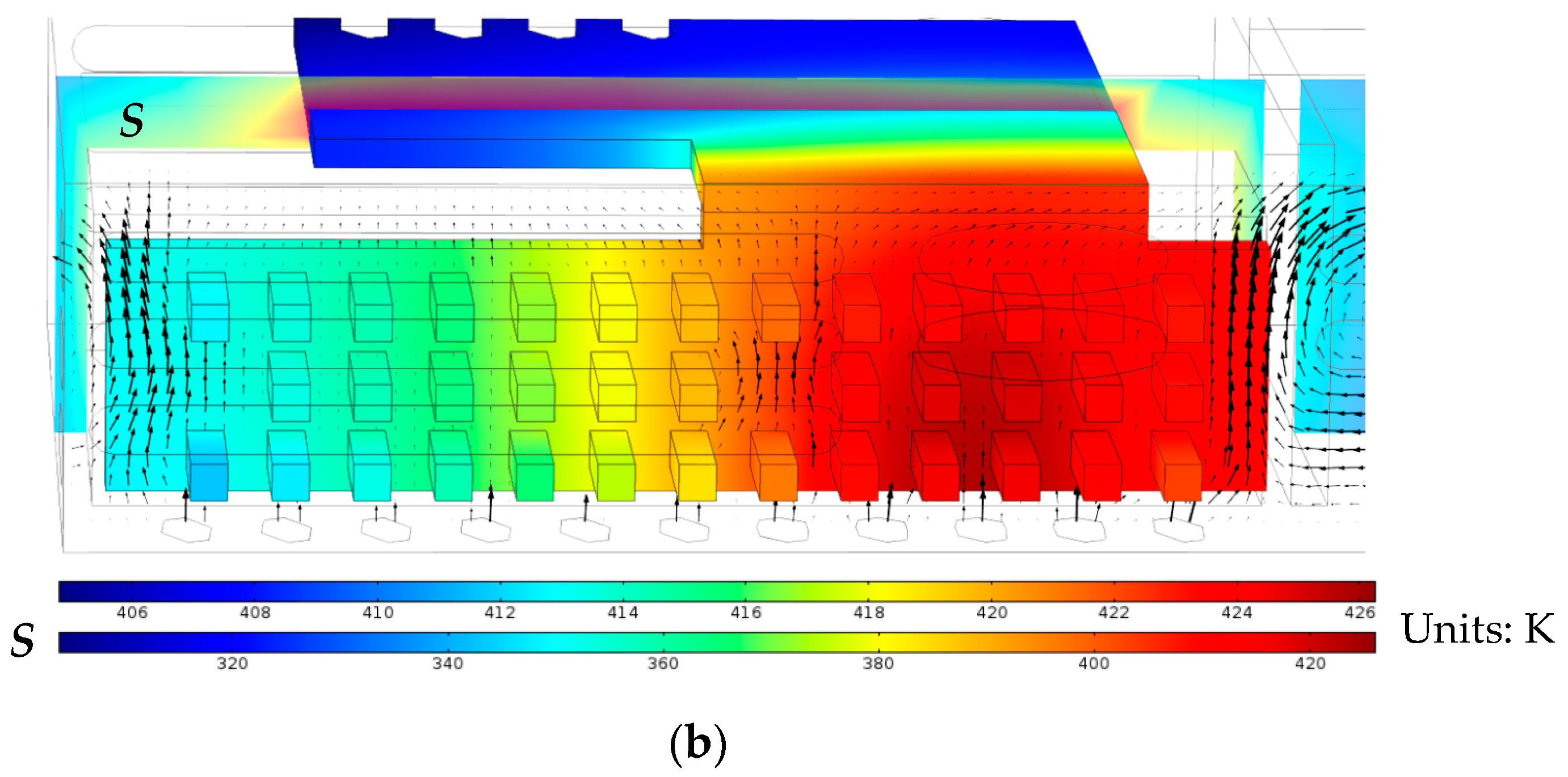
Figure 5 shows the temperature distribution on the entire heat sink surface and the airflow through the fins of the primary case of the handheld projector. The high temperature region around the second plate in
Figure 5a or the third row of the pin fin in
Figure 5b on the right denotes the heater position on the opposite surface of the fin array base. The noticeable temperature gradient on the heat sink plate shows a temperature difference of approximately 20 K between the hottest area around the junction of the heat sink plate and the fin array base and the coldest region on the heat sink plate. Because the clearance between the lower edge of the plates and the bottom openings is only 1.0 mm, the air intake through a few plates was blocked due to the inappropriate arrangement of the openings and the plate fins, and caused a nonuniform airflow indicated by the arrows between plates in
Figure 5a. However, the air inlet velocity through each opening in
Figure 5b is more uniform than that in
Figure 5a, because of the larger clearance between the lower edge of the lowest column of the pins and the bottom openings, 2.0 mm. In addition, the airflow velocity between two adjacent plates, which is 4.5 mm apart, in
Figure 5a is higher than that between pins in
Figure 5b because the more densely distributed pins, 1.75 mm, impose higher drag on airflow. The lower airflow velocity through pin-fin array attributes to a higher thermal resistance of the handheld projector having a pin-fin array as exhibited in
Figure 3a.
An arbitrary slice,
S, which shows both the air temperature between the horizontal heat sink plate and the upper case of the handheld projector, and the air temperature around the insulation block, is also presented in
Figure 5 with different temperature legend. The simulation results exhibited that the air within the spacing between the horizontal heat sink plate and the upper case of the handheld projector was almost stationary because of the tiny spacing, 1.5 mm. Therefore, conduction became the major heat transfer mode as the hot heat sink plate transferred heat across the thin air layer to the upper case, resulting in a peak temperature on the upper case surface in
Figure 3b.
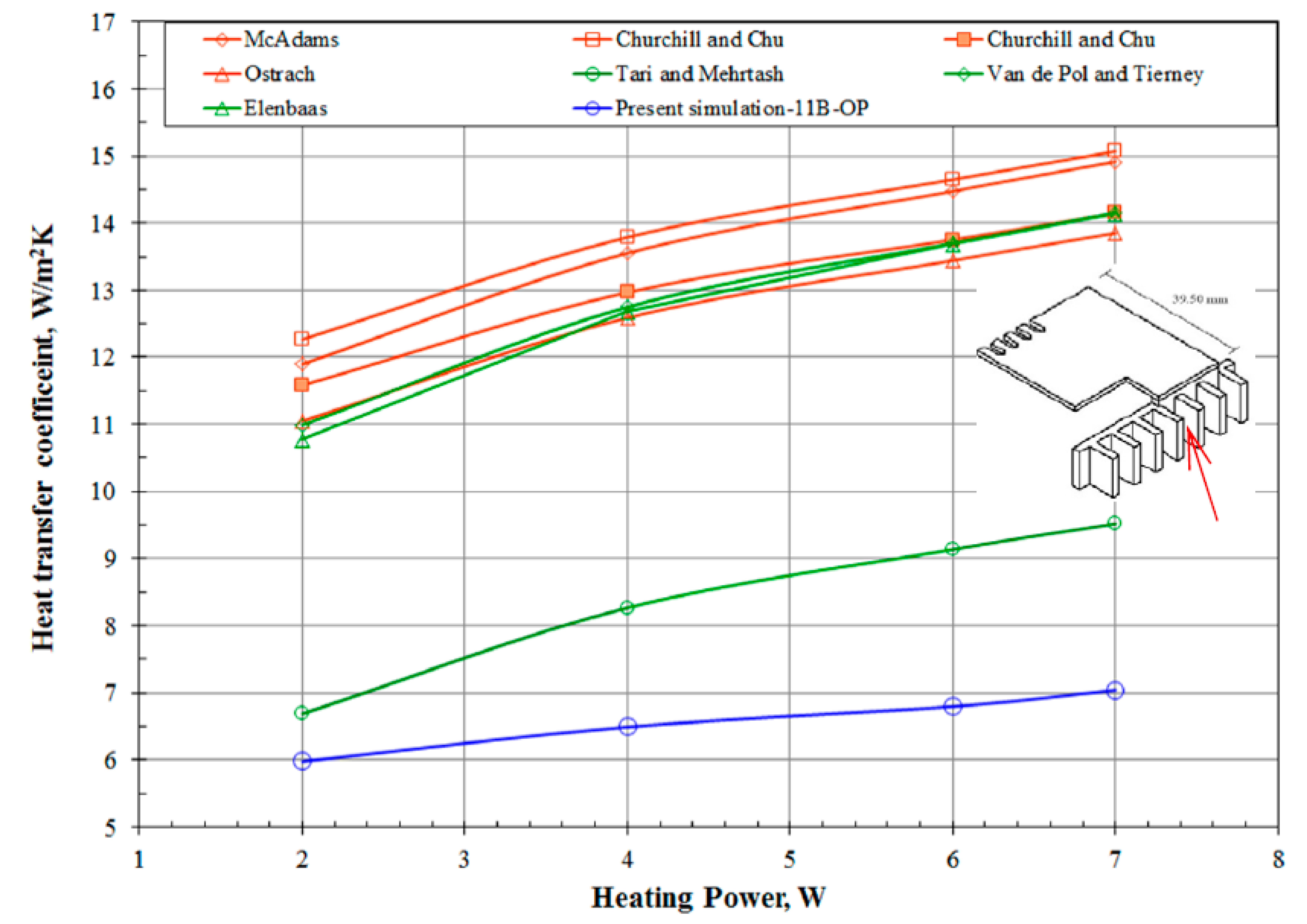
The heat transfer coefficient of one surface of the plates, which was erected above the heater and was indicated by a red arrow in the illustration in
Figure 6, in the primary handheld projector at various heating powers was estimated based on its average surface temperature and heat transfer rate obtained from the simulated results. In addition, the heat transfer coefficient of a surface with identical surface temperature and dimensions to the aforementioned surface in the plate-fin array in the study was also estimated using several selected correlations. Those selected correlations are applicable for the estimation of the heat transfer coefficient of either a vertical, single plate [
3,
4,
6] or a plate-fin array [
9,
11,
18] in an infinite, still medium.
Figure 6 demonstrates the comparison of the heat transfer coefficient among those data. It shows that the heat transfer coefficients of a single, vertical plate estimated by the correlations [
3,
4,
6], which are presented as orange curves, were higher than those of the plate-fin array placed in an infinite medium, which are presented as green curves, because of the boundary layer interference between two adjoining fins of the plate-fin array. However, the heat transfer coefficient of the plate-fin array installed in the primary handheld projector, which ranges from 6 W/m
2·K to 7 W/m
2·K, is even lower than that of the plate-fin array placed in an infinite medium. The deviation between the value predicted by the correlation [
18] and the present data continuously rises from 10% at 2 W to 26% at 7 W as show in
Figure 6. The significant difference is likely because the case of the handheld projector and the complicated layout in the handheld projector prevent the warm air around the fin array inside the handheld projector from discharging. Note that the selected correlations used for estimating the heat transfer coefficient of a plate-fin array is applicable to the condition that the plate-fin array has to be placed in an infinite, still medium. Such negative effect on the airflow would be more pronounced as the heating power increases because the air of extremely high temperature accumulates around the fin array. Therefore, the heat transfer coefficient of the plate-fin array in the handheld projector increased in a slower rate than those predicted by the correlations in
Figure 6 as the heating power increased. In fact, the heat transfer coefficient estimated by those correlations can be regarded as the upmost value that the heat transfer coefficient of the plate-fin array in the handheld projector can achieve. A better thermal design of the handheld projector achieves slighter difference in heat transfer coefficient between the value predicted by correlations and the actual heat transfer coefficient in the handheld projector.
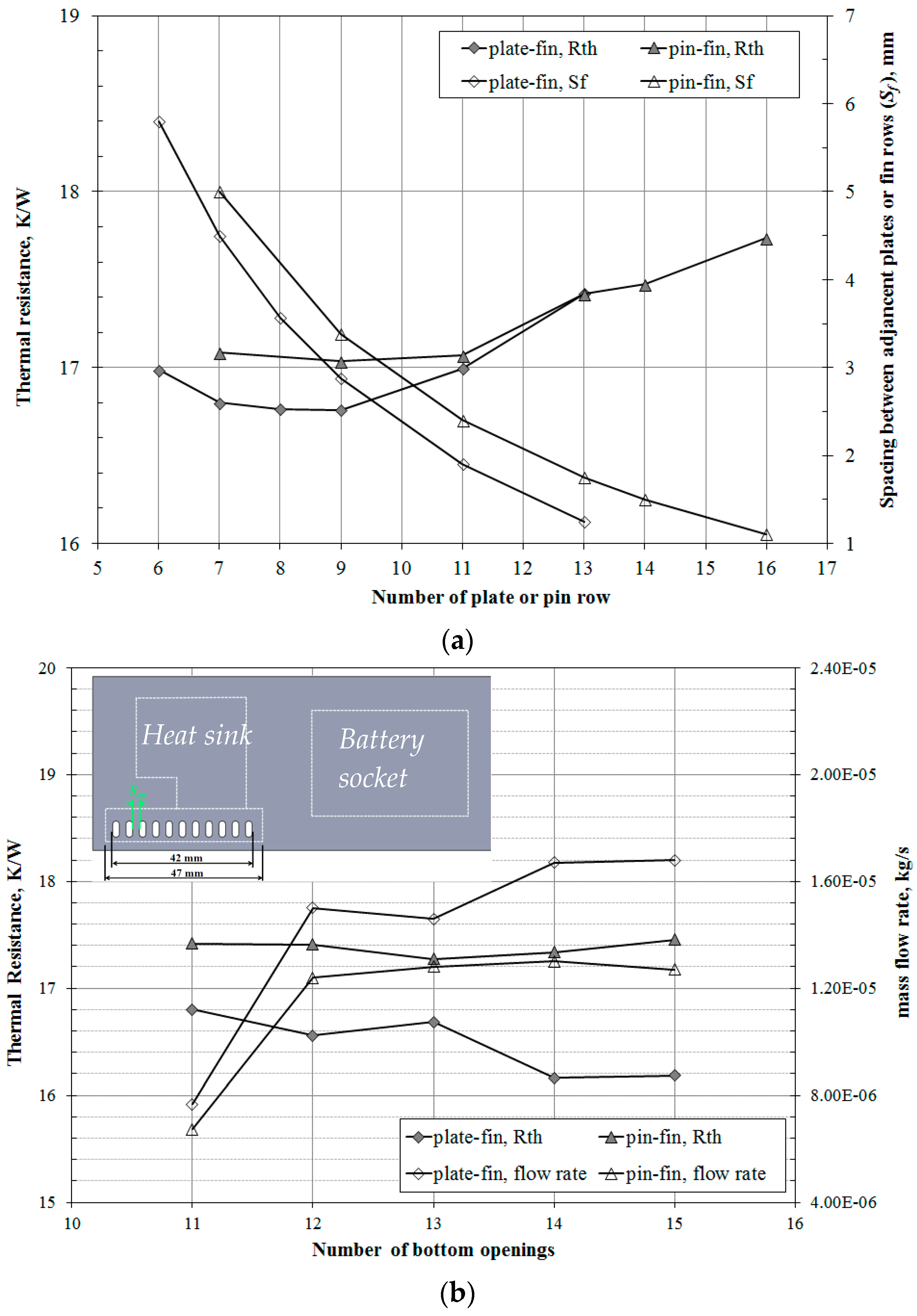
Subsequently, the effect of number of fin on the thermal resistance of the primary handheld projector was tested by gradually reducing the transverse spacing between two adjacent plates or pin rows,
Sf in
Figure 2, while keeping both the dimensions and the longitudinal spacing of each plate and pin indicated in
Figure 2 as constants. Note that handheld projector having a fin array of either 7 plates or 13 rows of square pin was considered as the primary case.
Figure 7a shows that the thermal resistance of the handheld projector having a plate-fin array reduced slightly as the number of plate increased from 7. However, as the number of plate was 9 and the spacing between plates was 2.875 mm, the thermal resistance of the handheld projector reached a minimum. Once the number of plate exceeded 9, the thermal resistance rapidly increased as the number of plate increased. The reason that causes the concave thermal resistance curve is the existence of an optimal spacing for the fin array. Although heat transfer from each plate decreases with decreasing transverse spacing, the number of fins that may be placed in a prescribed volume increases. Hence, the optimal spacing maximizes heat transfer from the array by yielding a maximum for the product of heat transfer coefficient and the total fin surface area.
Figure 7a suggests that the optimal spacing between plates falls around 2.875 mm in the present plate-fin array of nonuniform temperature as the heating power is 7 W. Based on the heater temperature that the simulation results yielded at 7 W for the primary handheld projector having plate-fin array, the optimal fin spacing for the plate-fin array would be 3.3 mm and 4.3 mm, estimated by the correlation proposed in [
11,
14], respectively. The larger optimal spacing that the correlation predicted was because the ambient temperature was defined as the air temperature outside the projector, 303 K, which caused an overestimated Ra number used in both correlations [
11,
14] since the actual air temperature surrounding the fin array would be considerably higher than 303 K. Similar variation trend of the thermal resistance to the abovementioned case also occurred as the handheld projector was equipped with a pin-fin array as shown in
Figure 7a. The thermal resistance slightly reduced as the row of pin fin increased from 7 to 9, which yielded a lowest thermal resistance with the spacing between pins of 3.375 mm, and then gradually increased as the pin row further increased. Although the trend of the thermal resistance variation in
Figure 7 between two different handheld projectors was similar, it illustrates in
Figure 7 that the thermal resistance of the handheld projector having a plate-fin array was more sensitive to the transverse spacing between fins.
Figure 7a also reveals that the pin-fin array in a shrouded and narrow environment like the present handheld projector demanded a larger transverse spacing than that of a plate-fin array to obtain a comparable thermal resistance, as the natural convection was the major heat transfer mode.
As the number of bottom openings of the primary handheld projector increased by reducing the spacing between openings,
Sop in
Figure 7b, while keeping the first bottom opening at the fixed position, the related variation of both the thermal resistance and the total mass flow rate of air entering the handheld projector through all bottom openings at a heating power of 7 W were shown in
Figure 7b. Note that the mass flow rate of the airflow was estimated by integrating the inner product of
and the area,
, over the entire surface of the lower case. It can be observed that the total mass flow rate of the air through those bottom openings substantially increased as the number of bottom openings began to increase, and then reached a plateau, irrespectively of the fin type. A significant drop and inflection of the mass flow rate occurred as the number of bottom openings was 13 on the handheld projector having a plate-fin array. It suggests that a few openings were blocked because of the inappropriate arrangement of the plate fin and the bottom openings, similar to the phenomenon revealed in
Figure 5. However, such concave shape of the mass flow rate did not occur in the other handheld projector having pin-fin array because of the larger clearance between the lower edge of the lowest column of the pins and the bottom openings as mentioned in
Figure 5.
Figure 7b also shows that the variation of the thermal resistance of the handheld projector exactly depends on the variation of air mass flow rate, regardless of the fin type in the handheld projector.
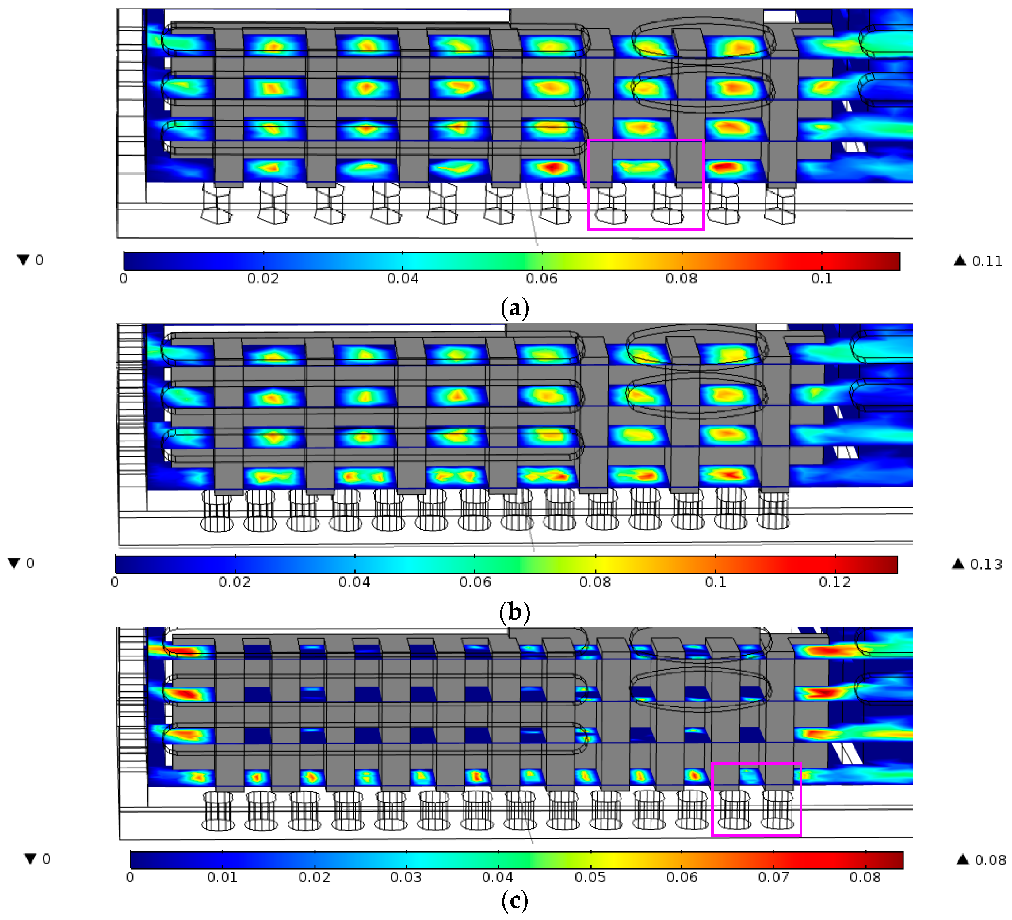
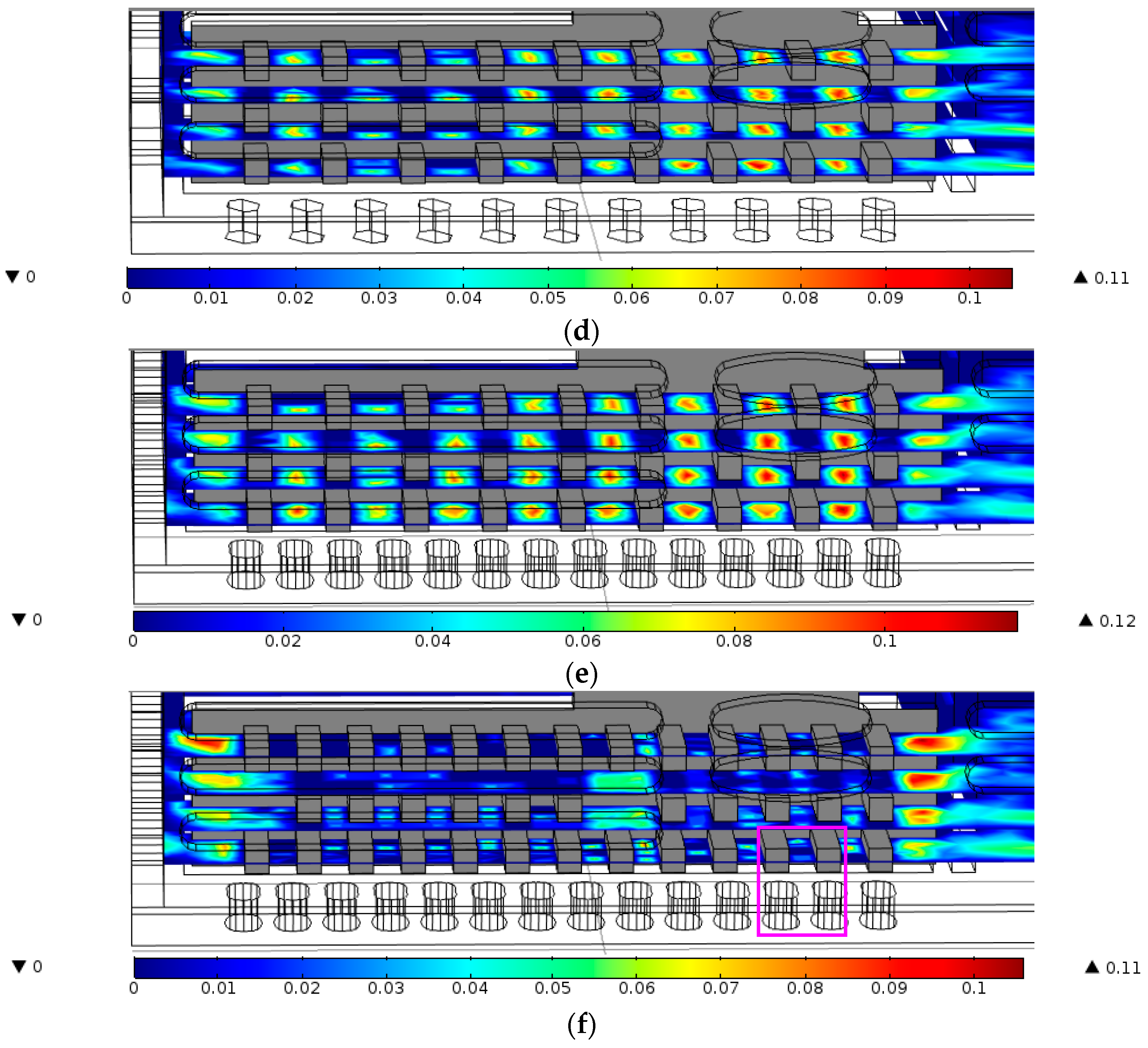
Figure 8 shows the airflow velocity contour on four different sections in the handheld projector which has different configurations of the fin array and openings. It can be observed in
Figure 8 that the velocity magnitude of the airflow between fins reduced as the number of fin increased, while the velocity magnitude of the airflow increased as the number of bottom openings increased, regardless of the fin type. However, the increase of bottom openings was not able to offset the reduction of the airflow velocity resulting from the increase of the number of fin as shown in
Figure 8a,c,d,f. In addition, the pink rectangles marked in
Figure 8a,c,f reveal that the inappropriate arrangement of the fins and the bottom openings blocked the air from entering the interfin region and reduced the airflow velocity.
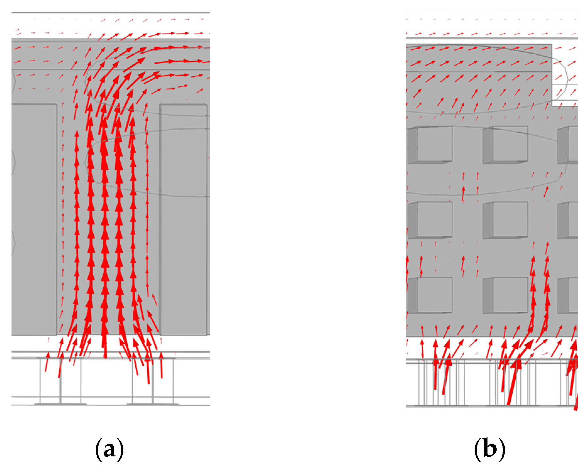
The velocity vector of the airflow within the pink rectangles in
Figure 8a,f are enlarged in
Figure 9a,b, respectively. In
Figure 9a,b show that the airflow can not flow straight after it passes through the bottom openings because the fin shading the openings forms a barrier that causes air to deflect before it enters the passage between fins. Such airflow deflection would reduce the airflow rate through the passage between fins because the airflow at the inlet has an angle with respect to the centerline of the passage.
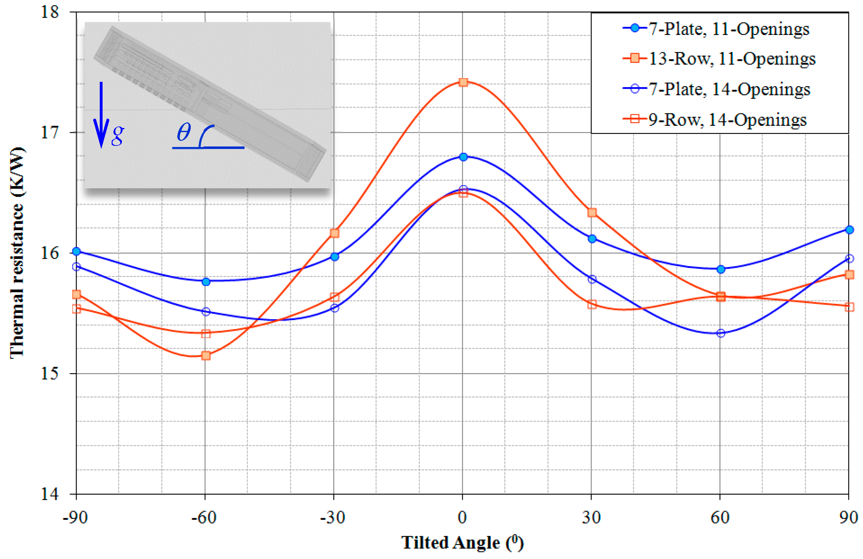
Figure 10 shows the orientation effect on the thermal resistance of the handheld projector with various combinations of fins and openings, including the primary cases denoted as “7-Plate, 11-Openings” and “13-Row, 11-Openings”, and the improved designs denoted as “7-Plate, 14-Openings” and “9-Row, 14-Openings”, as well. It can be seen in
Figure 9 that the thermal resistance of the handheld projector having either a plate-fin array or a pin-fin array significantly reduced as its tilted angle increased, and reached a minimum at
θ = 60°. As the tilted angle of the handheld projector further increased toward
θ = 90°, its thermal resistance increased. Moreover, the thermal resistance variation was almost symmetric with respect to
θ = 0°. The thermal resistance of the handheld projector having a plate-fin array was lower than that having a pin-fin array at a tilted angle less than 30°, while contrary results revealed at a tilted angle of the handheld projector between 60° and 90°. The reasons that cause the thermal resistance variation with the orientation of the handheld projector are associated with the arrangement of airflow direction and the openings on the handheld projector case. The airflow field will be elucidated in
Figure 11 and
Figure 12 at various orientations of the handheld projector.
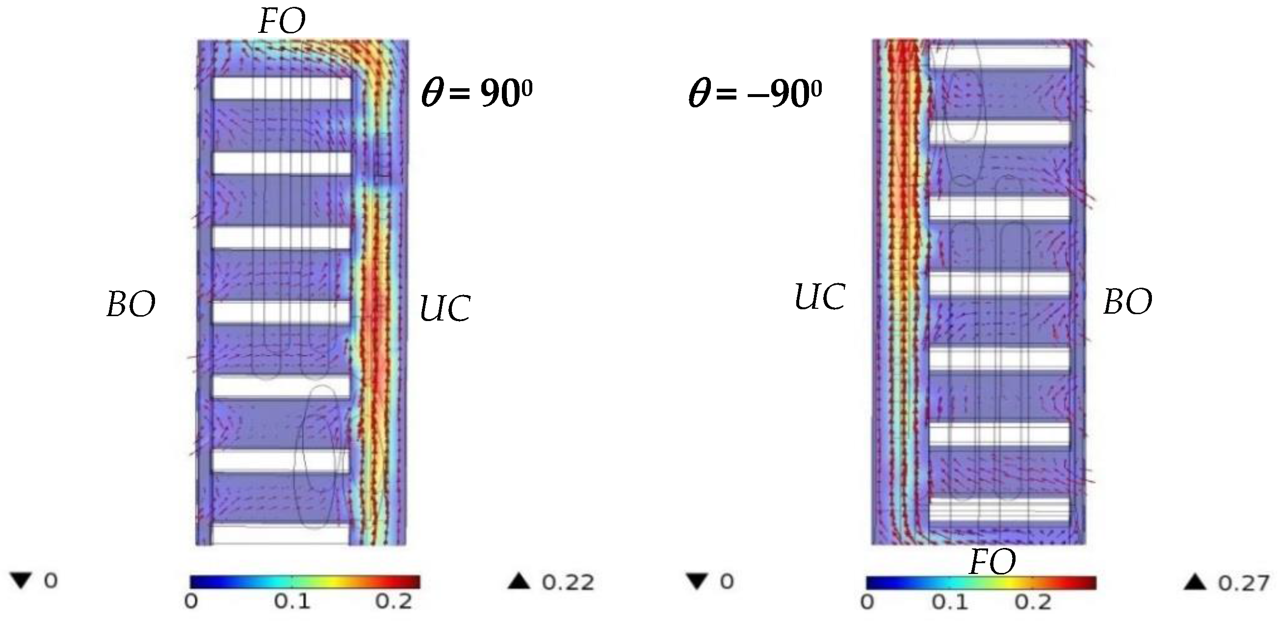
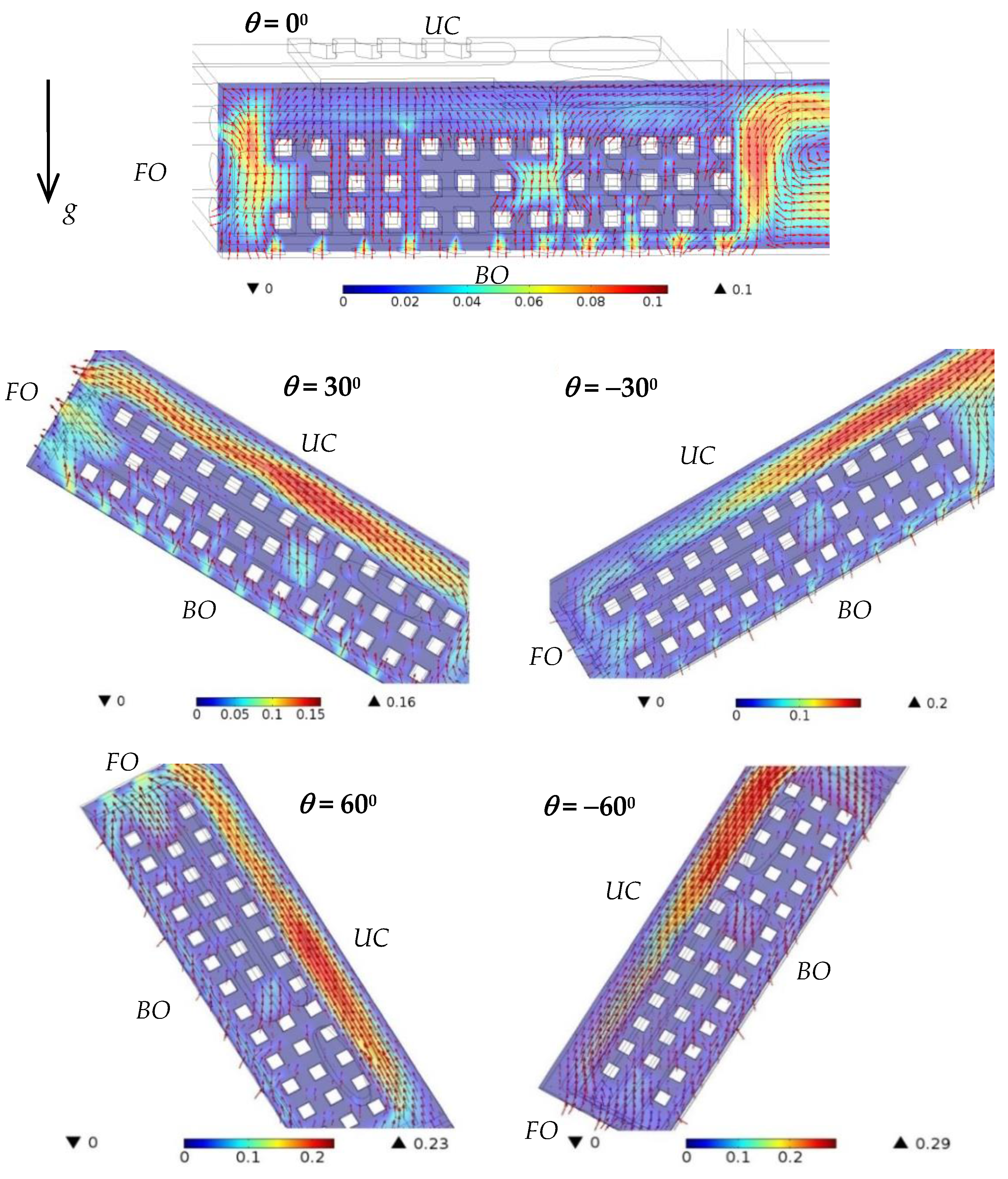
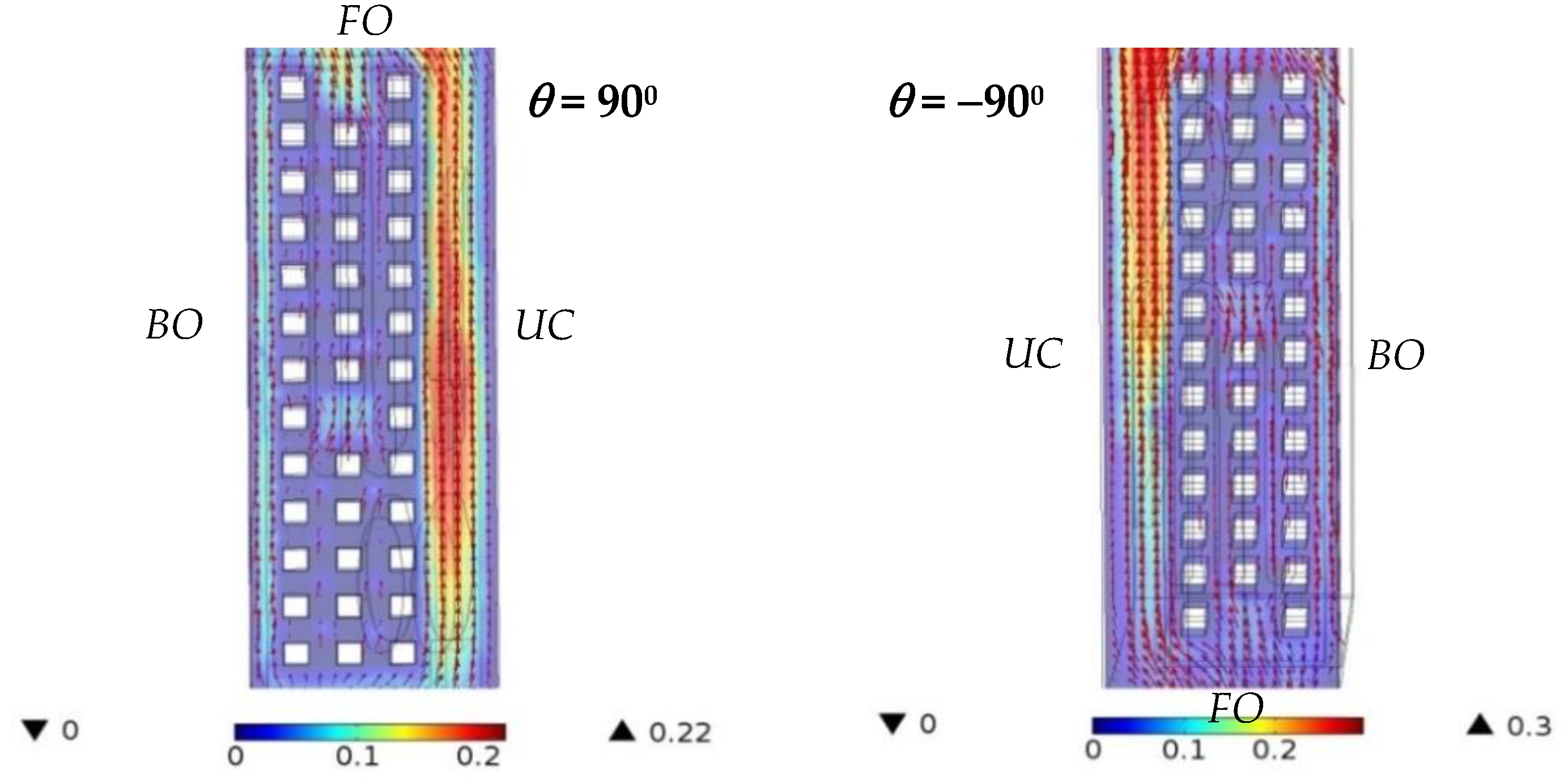
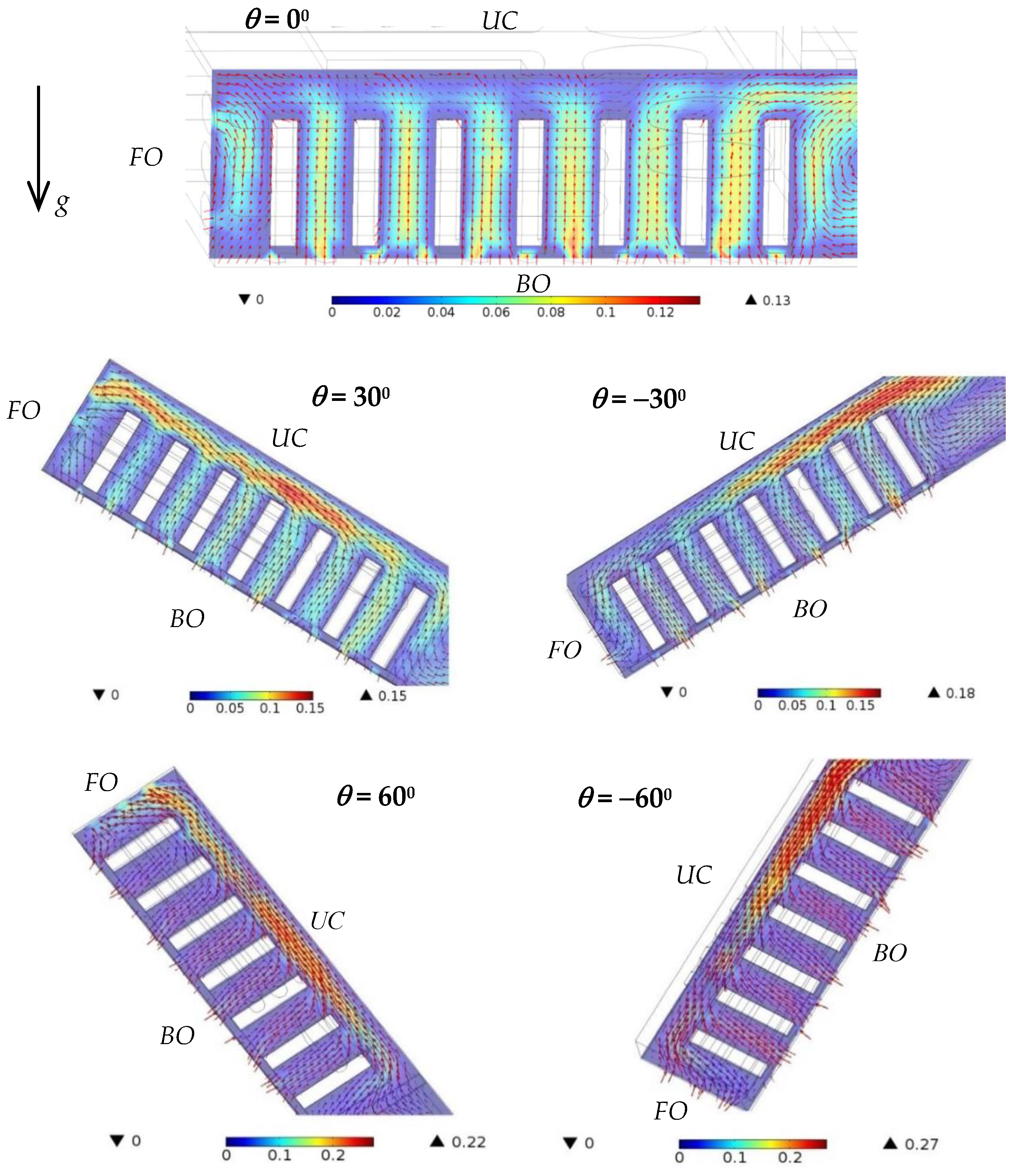
Figure 11 and
Figure 12 show the airflow velocity around the fin array in the primary handheld projector with various orientations at a heating power of 7 W. The upper case of the handheld projector, the location of the bottom openings and the front openings are denoted with
UC,
BO and
FO, respectively, in these figures for clear illustration. The white blocks, color and the arrows in these figures represent the fins, velocity magnitude and the airflow direction, respectively. As the orientation of the handheld projector was 0°, it can be observed in
Figure 10 and
Figure 11 that the air entered the handheld projector from every bottom opening and the lower front openings, and then moved upward through the space between fins, and finally left the handheld projector from both the side openings and front openings that were close to the upper case. As the tilted angles of the handheld projector were 30° and 60°, both figures show that not only the front openings, but those side openings close to the upper case were outlets for the airflow induced by the hot fin array, while the major inlets for the outside air were still the bottom openings. As the inclination of the handheld projector was 30° and 60°, after the air crossed the fins, it was accelerated toward the front openings with a maximum velocity around 0.15 m/s and 0.20 m/s, respectively, which was higher than the air velocity (0.08 m/s) within that region in a horizontal handheld projector. Therefore, this resulted in a lower thermal resistance of the slightly inclined handheld projector. Because the plate fins hindered the warm air from moving upward as the orientation of the handheld projector was upright (±90°), the surrounding air flowed into the handheld projector through each bottom openings was immediately discharged from the same openings. Under such circumstance, relatively small amounts of air were allowed to flow through the space between plates. However, unlike the flow situation when the tilted angle of the handheld projector was positive, the front openings became the inlets as the tilted angle of the handheld projector was negative. In addition, the air circulation adjacent to the fin located in the farthest position from the front openings would be gradually discharged from the nearby side openings, regardless of the orientation of the handheld projector.
The airflow around the pin-fin array in the primary handheld projector with various orientations was similar to that in
Figure 10. The major difference between the airflow presented in
Figure 11 and
Figure 12 is that the air was not discharged from the bottom openings as the handheld projector was held upright, ±90°, because the pin fin configuration allowed the warm air to rise through the spacing between fins, which led to a lower thermal resistance of the handheld projector having a pin-fin array at ±90° as shown in
Figure 10.


