Article

Distributed Control Strategy for Autonomous Operation of Hybrid AC/DC Microgrid

1
Energy Efficiency Research Division, Korea Institute of Energy Research, Daejeon 34129, Korea
2
Samsung Electronics, Suwon 16677, Korea
*
Author to whom correspondence should be addressed.
Energies 2017, 10(3), 373; https://doi.org/10.3390/en10030373
Submission received: 6 December 2016 / Revised: 13 February 2017 / Accepted: 10 March 2017 / Published: 16 March 2017
(This article belongs to the Special Issue Distributed Energy Resources Management)

Abstract

:
This paper proposes a distributed control strategy that considers several source characteristics to achieve reliable and efficient operation of a hybrid ac/dc microgrid. The proposed control strategy has a two-level structure. The primary control layer is based on an adaptive droop method, which allows local controllers to operate autonomously and flexibly during disturbances such as fault, load variation, and environmental changes. For efficient distribution of power, a higher control layer adjusts voltage reference points based on optimized energy scheduling decisions. The proposed hybrid ac/dc microgrid is composed of converters and distributed generation units that include renewable energy sources (RESs) and energy storage systems (ESSs). The proposed control strategy is verified in various scenarios experimentally and by simulation.

1. Introduction

To reduce carbon emissions, increased penetration of renewable energy sources (RESs) in power systems is desirable. This adoption of distributed energy resources can enhance energy security for local regions [1,2]. However, the effective utilization of intermittent RES generation and the integration of multiple distributed energy resources remain significant challenges. Furthermore, power quality and system reliability requirements are also increasing. Therefore, microgrids are attracting interest as alternative systems that could enable an intelligent power grid in the future, owing to the capability of microgrids to strengthen grid resilience and to enable the integration of distributed energy resources such as RESs, diesel generation, and energy storage systems (ESSs) [2,3,4,5].
A microgrid is a localized small grid that can operate in both grid-connected and off-grid modes to enhance energy security. Depending on the type of bus voltage, microgrids are categorized into ac, dc, and hybrid systems [6,7,8,9]. Comparing ac and dc systems, dc microgrid systems feature improved efficiency, requiring fewer conversion stages for RESs than ac systems. In addition, dc systems substantially reduce the impacts of synchronization and harmonic distortion, resulting in improved power quality compared to ac systems. However, low-voltage dc distribution systems require consideration of technical issues such as protection and grounding, as well as practical issues such as the limited number of commercially available dc components [10,11,12]. For these reasons, hybrid ac/dc microgrid systems are often investigated as alternative distribution networks. In hybrid ac/dc systems, there are separate ac and dc voltage buses for ac and dc loads, respectively, and the buses are interfaced through power electronics devices [7,13].
A microgrid contains multiple power electronics blocks connected to the system in parallel operation. These converters must be controlled to satisfy several essential microgrid requirements, including reliability, voltage regulation, and power sharing [14,15,16,17]. To address the aforementioned challenges, a number of control approaches have been proposed in microgrid applications. The control approaches can be divided into two classes based on their architectures: centralized and decentralized [17,18,19,20,21,22]. The centralized strategy increases efficient energy management through high-level communications, but is inadequate for microgrids requiring high reliability and scalability. The decentralized strategy, which is usually based on a droop scheme in a local controller, has improved reliability and facilitated power sharing without the need for communication between the components, although mode transition flexibility and optimized energy management are restricted [8,23,24,25,26].
This paper proposes a distributed control strategy for autonomous operation of a hybrid ac/dc microgrid. A hybrid ac/dc microgrid is considered in which distributed generation units and ESSs are connected to the dc bus as shown in Figure 1. The overall control structure is formulated with low-speed communication between two layers of controllers: the primary decentralized local controllers and the higher central controller. This hybrid control strategy enables autonomous operating mode transitions including in a fault situation; a supervised controller is not required because operating modes are based on events and bus voltage levels. The central controller executes an energy management system (EMS) to optimize the energy utilization of the system. Optimal energy scheduling is derived based on a dynamic programming method, using the information measured by the local controllers. To minimize energy costs, both the state of charge (SOC) and energy fluctuation trends are considered, and the optimal power dispatch is performed by adjusting the offset voltage level. The control architectures of the converters are discussed in more detail in Section 2 and Section 3.
The local controllers are operated following the droop control method and are designed to inspect the operation conditions of each power electronics block: (1) the grid-interfaced converter (GC) manages islanding and reconnection to the grid; (2) the storage converter (SC) is used to implement the energy management strategy for energy optimization; and (3) the RES converter (RC) maximizes the RES output power.
The paper is organized as follows. In Section 2, the overall system structure of the proposed hybrid ac/dc microgrid is described, and the fundamental control philosophy of the proposed strategy is introduced, with descriptions of the converters’ operation modes. In Section 3, the design method of the central control is discussed, with a mathematical formulation of the EMS strategy and its brief results. Section 4 presents primary control designs for different power sources with different control objectives. In Section 5, the proposed control strategy is experimentally verified in various scenarios. Finally, Section 6 presents the conclusions.

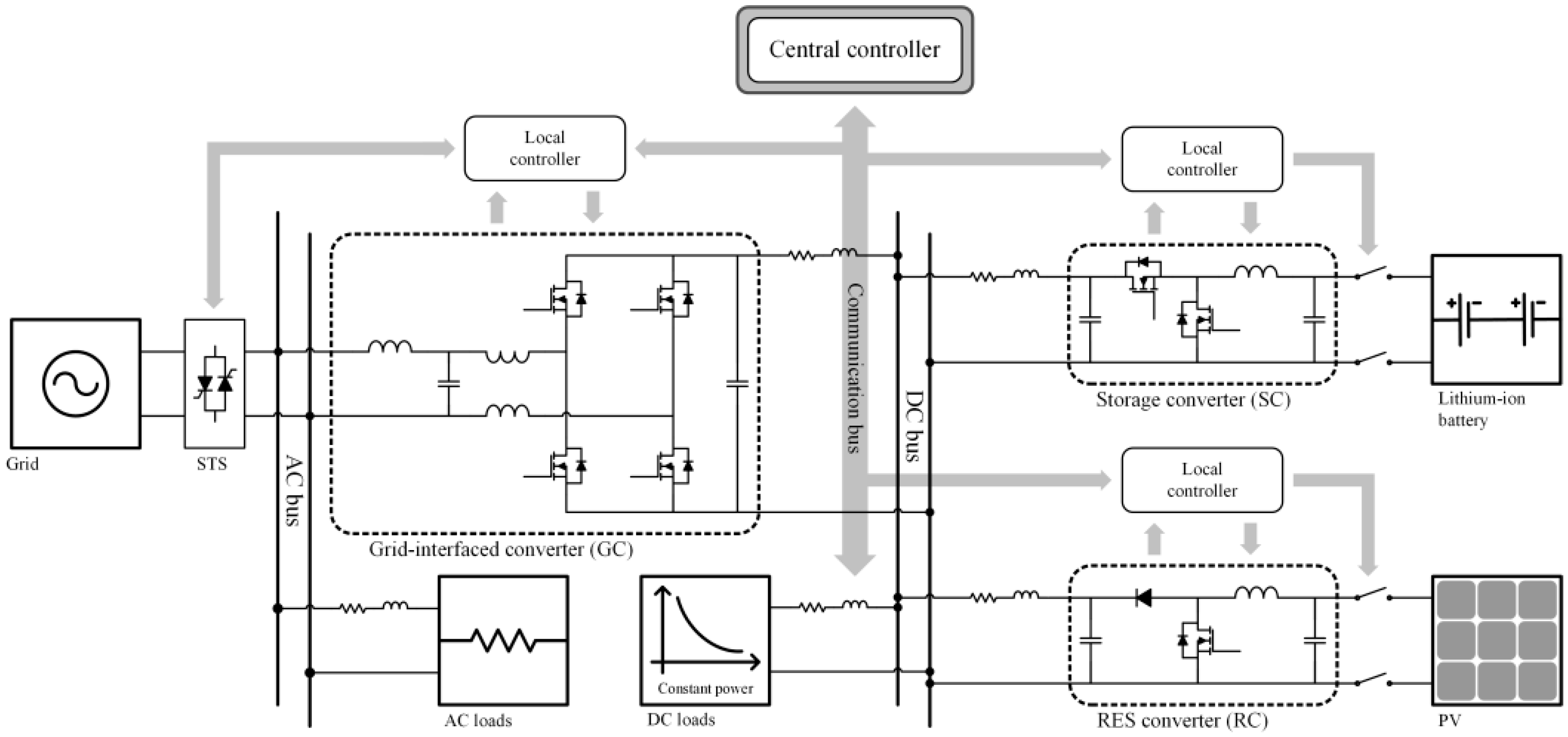
2. Configuration and Control Strategy of a Hybrid AC/DC Microgrid

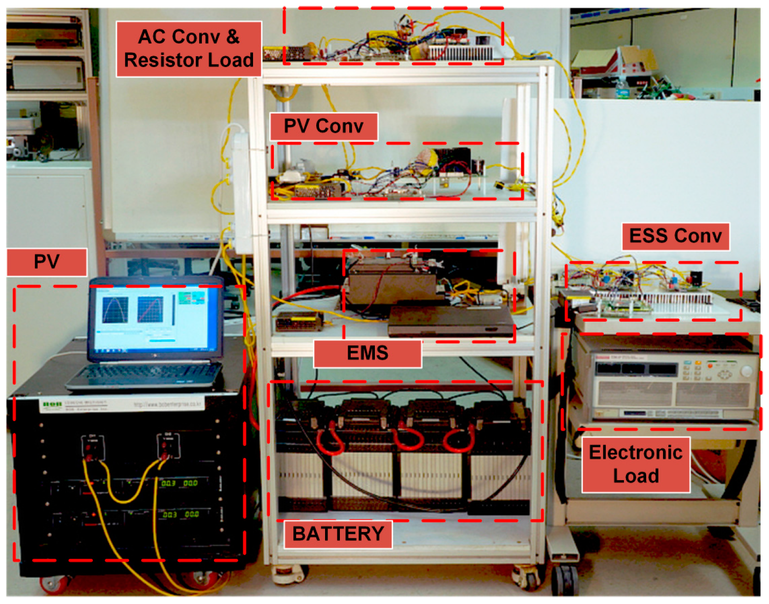
2.1. System Description

Figure 1 diagrams the entire system, including the electric network and communication network. The proposed microgrid consists of a photovoltaic (PV) RES, ESS, and utility grid, all of which are coupled to the bus using converters. Ac and dc loads are connected to each bus. The loads are either a resistive load or a constant power load. Connection of the distributed generation units to the dc bus improves the system efficiency by reducing the number of conversion stages if the combined generated power is consumed in the dc network. Moreover, connection to the dc bus eliminates the control issues associated with synchronization and reactive power. The static transfer switch can connect and disconnect to the utility grid by fault signals or by a supervisory control strategy. The dc bus is interfaced to the ac bus through an ac/dc converter. The GC located between the ac bus and the dc bus works as a rectifier to regulate dc bus voltage during grid-connected operation, and as an inverter to form the ac bus and feed the ac load during off-grid operation. The topology of the GC is a single-phase voltage-source converter with an LCL filter. A lithium-ion battery set as an ESS is connected through a bidirectional synchronous buck converter. The PV source is the RES and is connected to the dc bus through a boost converter. The RC performs the maximum power point tracking (MPPT).
The local controllers of each converter share a single communication bus. Each local controller measures local voltage and current, and controls the dedicated converter and the switch of the nearby source. The specific designs of these controllers will be detailed in the Section 3 and Section 4.

2.2. Control Strategy

The overall control structure is formulated with two layers. To retain reliability, primary local control is based on an adaptive droop method. Considering the source characteristics and operating mode, local controllers regulate bus voltage or perform MPPT. Because bus voltage is shared, each local controller can realize seamless mode transitions. To operate the microgrid efficiently, a central controller optimizes the EMS using a dynamic programming algorithm to optimize the battery usage schedule. The resulting commands are implemented by a droop curve compensator in the SC’s outer controller. In this manner, in which the droop-based local controllers are coordinated with the central controller, the system reliability and efficiency are greatly enhanced. The objectives of the proposed control design are listed as follows.
• Reliable and Autonomous Control
To avoid a single point of failure due to device or communication malfunction, the converters are controlled in a decentralized manner using a droop-based method. In addition, the operating modes of converters transition autonomously during unpredictable situations to improve the power system’s resilience.
• DC Bus Voltage Regulation
Regulation of the dc bus voltage (e.g., at 380 V), is one of the power quality criteria required of a dc microgrid. To overcome the poor voltage regulation of the typical droop method, the GC adjusts dc voltage offset.
• Energy Optimization
Energy optimization is performed to maximize the benefits of RESs and the ESS. An EMS module in the central controller obtains energy scheduling for optimization solutions and communicates the derived scheduling to the SC.
Based on the operation requirements above, Table 1 classifies the operating modes of the converters, including failure cases. In this classification, states of the entire system are characterized by combining the states of each converter. For example, State 121 represents the operating condition in which GC regulates Vdc under grid-connected conditions, SC regulates PESS for the EMS, and RC performs MPPT.
The shaded cells in Table 1 can be implemented using the adaptive droop-based method. The droop curves of each converter are shown in Figure 2, in which Figure 2a–c show the GC, SC, and RC curves, respectively. The GC curve shifts vertically to compensate for the dc voltage deviation. The SC curve can be expanded within the shaded region to achieve the required power control and SOC compensation. The RC performs an autonomous mode transition between MPPT and off-MPPT without any curve manipulation. According to the grid condition, the GC performs a seamless transition from the grid-connected mode to the off-grid mode, in which case, from the perspective of the dc bus, only the SC and RC regulate the dc bus voltage in droop control, while the GC appears as a load.

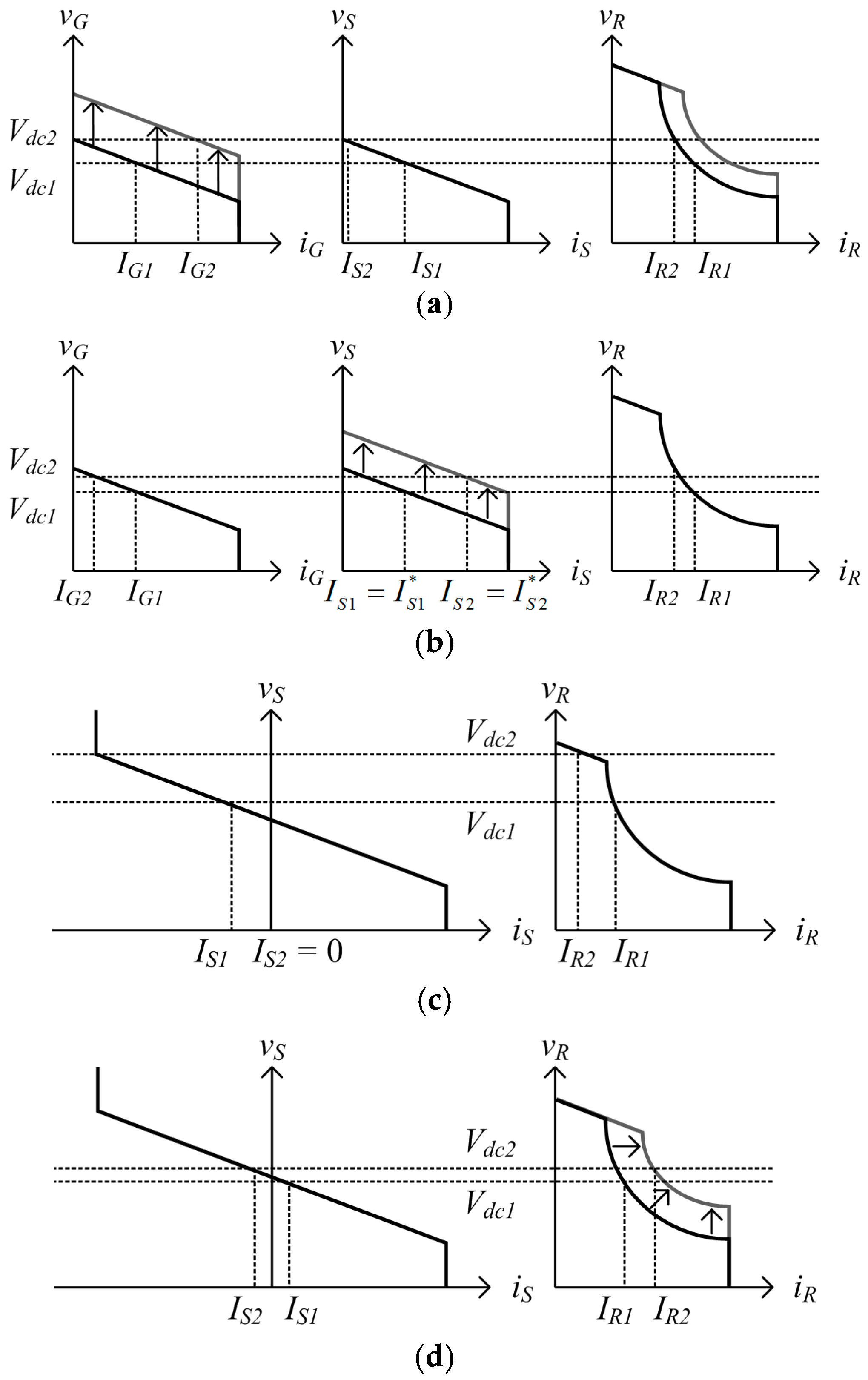
2.3. Operation Description

Figure 2 shows the VI curves of the converters, where iG, vG, iS, vS, iR, and vR represent the currents and voltages of the GC, SC, and RC, respectively. From these curves, in the ideal case, the steady-state operating points of the dc bus under the droop control are determined by
v d c = v G = v S = v R
i L = i G + i S + i R
in which vdc is the dc bus voltage, and iL is the total dc load current. In this subsection, several examples of system operation will be described to highlight the features of the proposed control scheme. This series of examples shows operational transitions, in which IG, IS, and IR are the steady-state currents of the GC, SC, and RC, respectively, and vdc is the steady-state dc bus voltage. In the following examples, shown in Figure 3, the steady-state value vdc1 moves to vdc2 after the relevant transitions, and the other values shift accordingly. Assuming constant load consumption, the following relationship is satisfied.
I L = I G 1 + I S 1 + I R 1 = I G 2 + I S 2 + I R 2
• DC Bus Voltage Compensation at State 111
According to Table 1, this state represents the condition in which the GC and SC regulate the dc bus voltage and the RC performs MPPT of the PV RES. Because the dc bus voltage vdc1 is less than the nominal voltage of 380 V, an additional outer loop of the GC compensates for the voltage deviation, as shown in Figure 3a. Consequently, the GC curve shifts upward until the steady-state voltage vdc2 is regulated to 380 V. The operating points of the other converters also change: the RC remains in MPPT, and the SC’s output power returns to zero in steady-state.
• EMS at State 121
State 121 is identical to State 111, except that the SC operates in the EMS mode. The objective of the SC’s local controller is to regulate the output power to the reference given by the central controller. Before the transition, the reference from the central module is IS1. When the reference increases to IS2, the SC curve shifts upward until the output current reaches the reference as shown in Figure 3b.
• Reliability under Failure from State 311 to State 332
At State 311, the GC is not involved in the droop control of the dc bus. At least one of two sources, the SC and/or RC, should operate in the dc bus voltage regulation mode. After a transition in which the SC fails, the RC may regulate the dc bus’s voltage level. If total load power is less than the maximum PV power, the dc bus voltage is regulated by the RC as shown in Figure 3c. Even if the irradiation changes, the RC tracks the new maximum power point while maintaining the dc bus voltage as in Figure 3d.

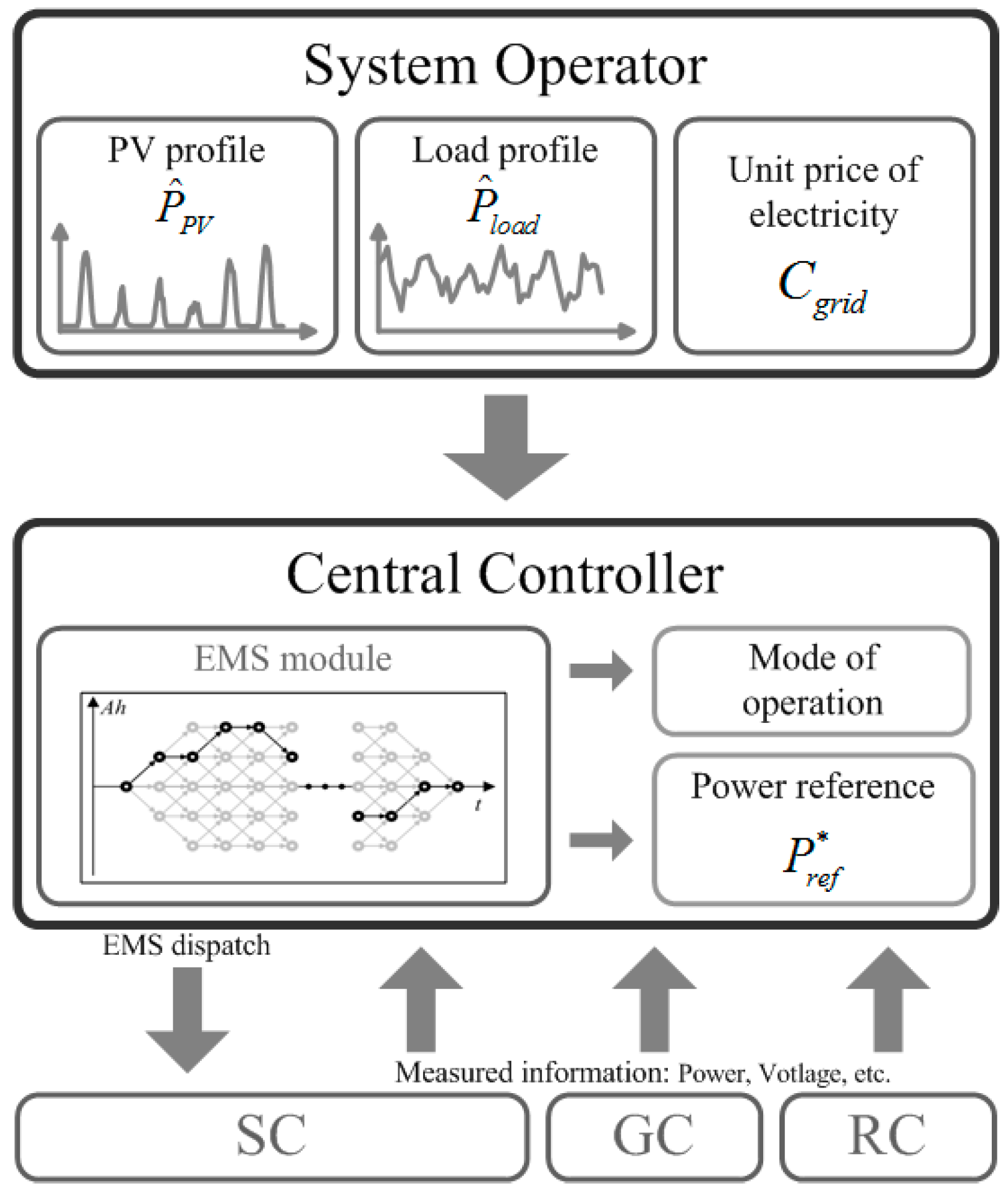
3. Control Design: Central Controller

As shown in Figure 1, the central controller shares the communication bus with the local controllers. Table 2 shows the information that the central controller processes for each local controller. In this section, the EMS feature of the central controller is highlighted. Inputs from the local controllers for this energy scheduling optimization stage include the source and load power information and the SOC of the battery; additional inputs include meteorological and pricing information from a higher-level operator, such as a distribution system operator as shown in Figure 4. The EMS scheme is implemented using a dynamic programming method. After an optimal solution is derived by the EMS module, the central controller dispatches the EMS power reference and operation mode to the SC.

3.1. EMS Optimization

Determining the optimal energy dispatch solution for the battery’s charge and discharge profile is accomplished by a shortest-path problem in which the path length represents the operator-defined cost. Using the previous and estimated RES generation profile and the load consumption profile, an optimal energy scheduling solution is derived to minimize the objective function under a set of constraints associated with the problem.
The EMS optimization is solved by a dynamic programming method. With hourly profiles of the RES and load power, the cost of the objective function is calculated for every hour t. Scheduling 1 day ahead, the path with the lowest cost from 1 h to 24 h is determined.
(1) Objective Function
The objective function is defined as in (4), where T is the total time of a day. J1[t] is the grid electricity consumption, which is computed by multiplying the grid power Pgrid and the unit electricity cost Cgrid. Pgrid is the net energy consumed by the utility during 1 h. Electricity cost is based on time-of-use pricing, which is set for a specific time period in advance of the calculation. J2[t] is the equivalent cost of battery usage at time t, where α is a weighting factor and Ah[t] is the state variable. The weighting factor is calculated to reflect the battery’s cost and life cycle. J2[t] is proportional to energy transferred to and from the battery, which includes both charging and discharging energy; therefore, this term can restrict indiscriminate battery usage.
J = t = 1 T ( J 1 [ t ] + J 2 [ t ] ) where J 1 [ t ] = P g r i d [ t ] C g r i d [ t ] J 2 [ t ] = α Δ A h [ t ]
(2) State Variable
The state variable is defined as the energy flow of the ESS, as determined by the integration of the battery current over time, following (5).
A h [ t ] = k = t 1 t i b a t [ k ]
(3) Input
Estimated PV generation PPV, load consumption Pload, and electricity pricing information Cgrid are given from the distribution system operator.
(4) Constraint 1
Power processed by the GC is calculated as:
P G [ t ] = P l o a d [ t ] P S [ t ] P R [ t ]
where PG[t], PS[t], and PR[t] are the power delivered to the dc bus by GC, SC, and RC, respectively; Pload[t] is given as an input. Using ηG, ηS, and ηR as the conversion efficiencies of the GC, SC, and RC, respectively, PS[t] is computed as
P S [ t ] = { 1 η S i b a t [ t ] v b a t [ t ] , ( charge : i b a t [ t ] 0 ) η S i b a t [ t ] v b a t [ t ] , ( discharge : i b a t [ t ] > 0 )
where ibat and vbat are the current and voltage of the battery terminal, and the conversion efficiency is applied according to the direction of power flow. PR[t] is obtained as:
P R [ t ] = η R P P V [ t ]
and the inflow grid power Pgrid is:
P g r i d [ t ] = { 1 η G P G [ t ] , ( import : P G [ t ] 0 ) η G P G [ t ] , ( export : P G [ t ] < 0 )
Estimated PV generation PPV, load consumption Pload, and electricity pricing information Cgrid are given from the distribution system operator.
(5) Constraint 2
To maintain a constant SOC level of the battery at the beginning and the end of EMS cycle, the net stored energy during a day is maintained at zero:
A h [ t = T ] = A h [ t = 0 ] = 0

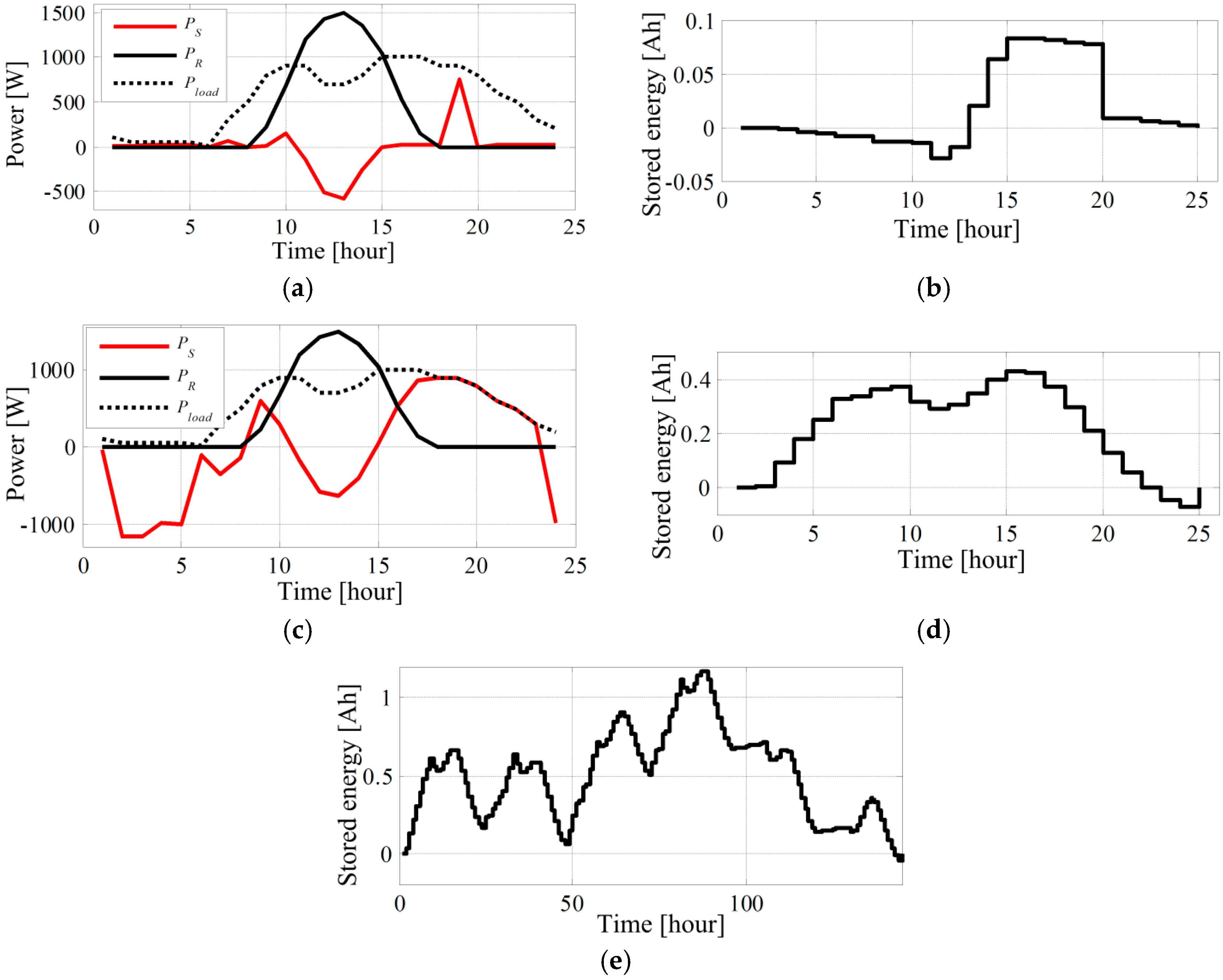
3.2. Energy Scheduling Results

Figure 5 shows the simulated results of the EMS formulated above where PS, PR, and Pload are one day’s SC, RC, and load consumption power profiles, respectively. Figure 5a,b show the optimization results of the proposed EMS with fixed pricing. It is seen that the SC tends to charge the battery during the day when the PV generation is larger than the peak load. Figure 5c,d show the optimized profiles with variable pricing. Because the price during the night is lower than during the day, the SC charges the battery during the night and during the peak generation time, and discharges the stored energy during the peak load at early morning and late evening. In both cases, the net stored energy at the beginning and the end of the day is zero to satisfy the constraint. Figure 5e shows the optimization result of scheduling 6 days ahead. The calculated results are dispatched to the local controller. Even in the case of a communication failure, the dc bus voltage can be maintained by adopting the adaptive droop method; thus, the proposed method does not require high-bandwidth communication.

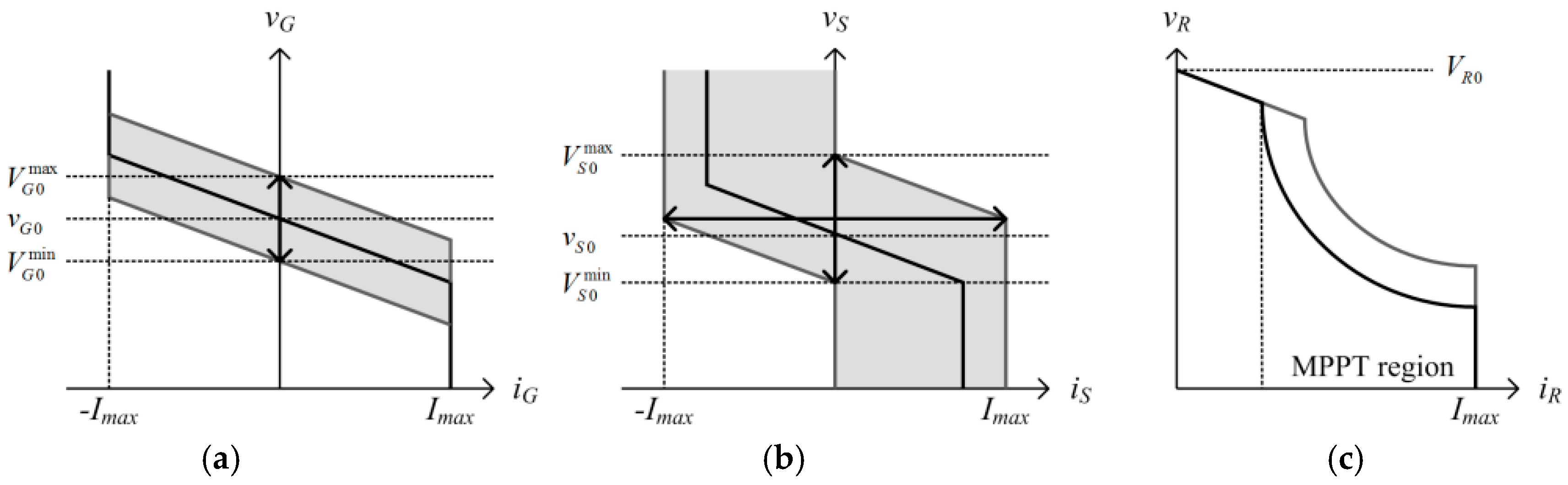
4. Control Design: Local Controllers

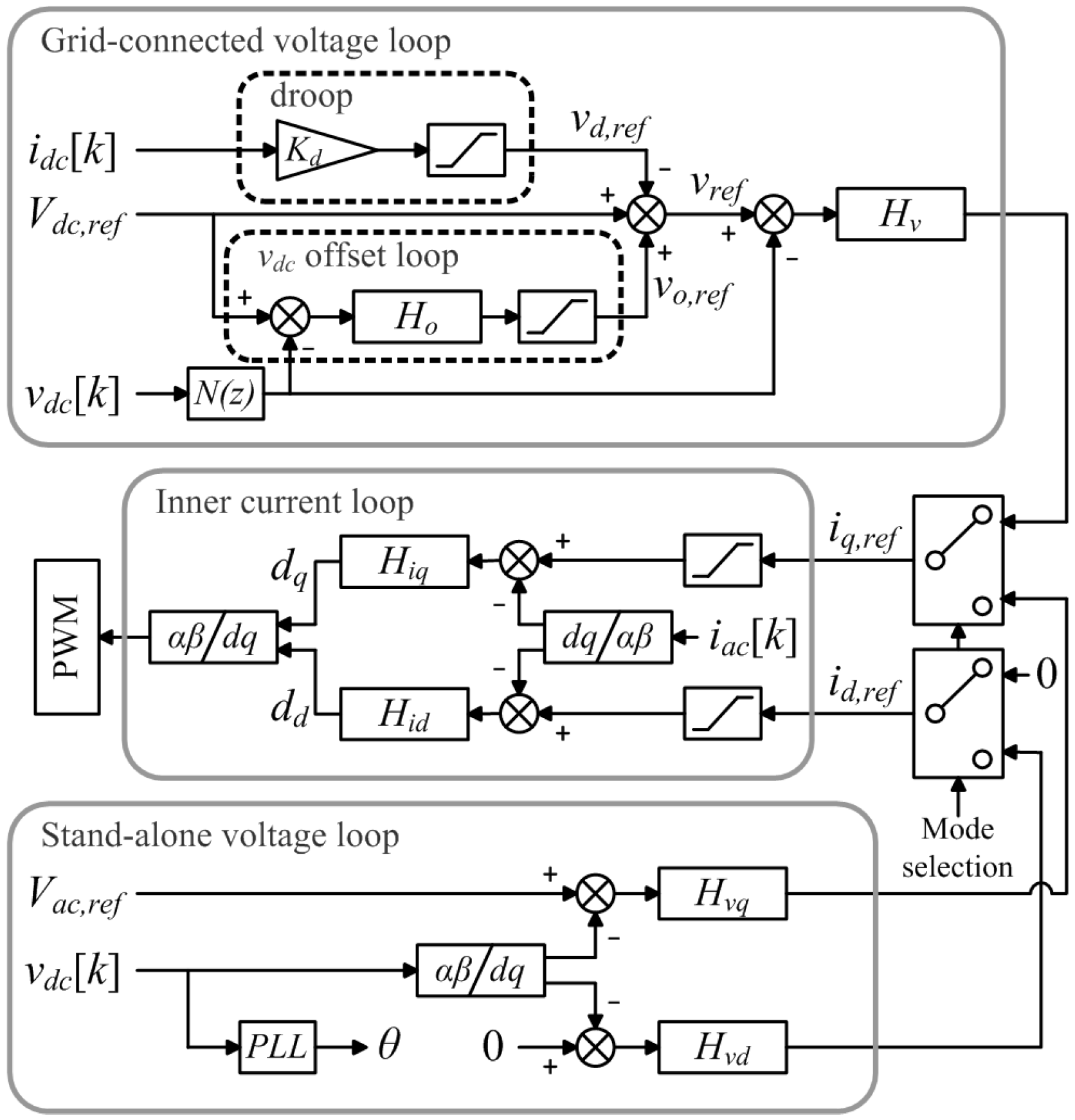
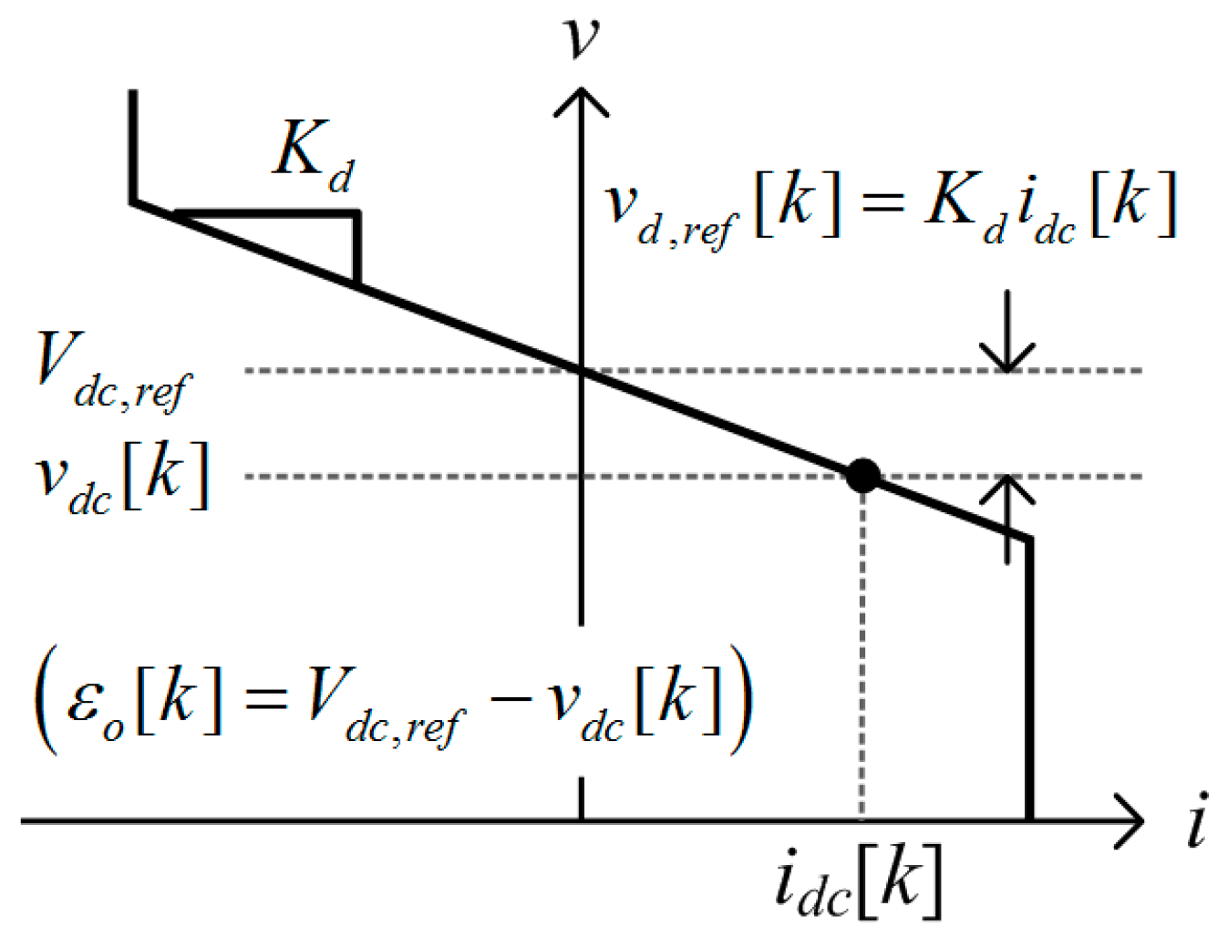
4.1. GC Local Controller

Figure 6 shows a block diagram of the GC’s local controller. The measurement variables are idc, vdc, iac, and vac, which are the currents and voltages at the dc and ac terminals, respectively. As described in Table 1, the GC is controlled in two different modes: the grid-connected mode and the off-grid mode. For both modes, the single-phase d-q current-loop is used to effect seamless mode transition. The current references, iq,ref and id,ref, are selected according to the operation mode. In the grid-connected mode, the voltage-loop is composed of two sub-blocks. The voltage reference, vref[k], is computed using two additional terms:
v r e f [ k ] = V d c , r e f v d , r e f [ k ] + v o , r e f [ k ]
where Vdc,ref is the nominal dc bus voltage (i.e., 380 V), and vd,ref[k] is the droop voltage given as
v d , r e f [ k ] = K d L P F ( i d c [ k ] )
where Kd is the droop gain, and LPF(∙) is a low-pass filtering function. vo,ref[k] is the offset for the dc bus voltage restoration, which is given as
v o , r e f ( z ) = H o ( z ) ε o ( z ) where   ε o ( z ) = V d c , r e f N ( z ) v d c ( z )
Ho(z) is a low-band-width PI-controller for the offset loop, and N(z) is a 120 Hz notch filter to eliminate the 120 Hz ripple in the vdc. The error between the nominal reference and vdc[k] is compensated by a slow PI controller to restore the deviation induced by the droop control. The relationship of the terms in (11) is shown in Figure 7. At a certain operating point, vd,ref[k] is determined by the droop gain and the output current, and then the error, εo[k], is computed to restore the voltage to the nominal level (i.e., 380 V). The voltage restoration information vo,ref[k] is transmitted to the central controller. vd,ref[k] and vo,ref[k] in (11) are processed through two limiters, both of which are designed to consider the droop gain and the maximum current rating of the converter, as in:
v d , r e f max = V d c , r e f + K d I max v d , r e f min = V d c , r e f K d I max

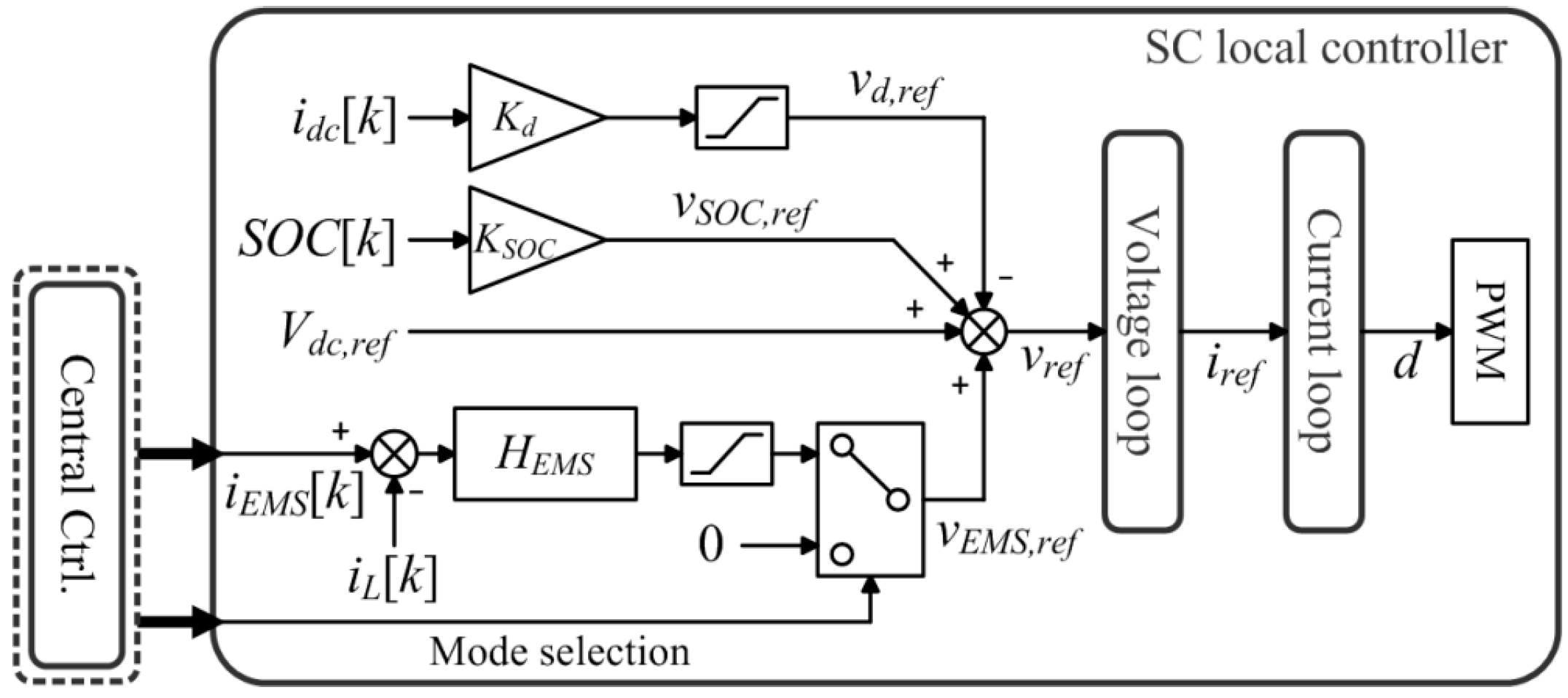
4.2. SC Local Controller

The block diagram of the SC’s local controller is shown in Figure 8. Although the converter is controlled by a two-loop controller, the detailed diagrams of the current- and voltage-loops are not depicted. The voltage reference is given as:
v r e f [ k ] = { V d c , r e f v d , r e f [ k ] + v S O C , r e f [ k ] , ( Mode = 1 ) V d c , r e f v d , r e f [ k ] + v S O C , r e f [ k ] + v E M S , r e f [ k ] , ( Mode = 2 ) ,
where vd,ref is the droop voltage, and vSOC,ref is the droop offset to reflect the SOC of battery, computed as:
v S O C , r e f [ k ] = ( S O C [ k ] 0.5 ) K S O C
where KSOC is a weighting factor. vSOC,ref[k] is zero when SOC[k] is 0.5. When SOC[k] is less than 0.5, vSOC,ref[k] becomes positive, and the converter will tend to lower the output of the battery. When SOC[k] is greater than 0.5, vSOC,ref[k] becomes negative, and the converter will tend to increase the output of the battery. When the mode of the controller is switched to Mode 2 by the signal from the central controller, the additional term vEMS,ref[k] becomes effective, which is given as:
v E M S , r e f ( z ) = H E M S ( z ) ε E M S ( z ) where   ε E M S ( z ) = Z { i E M S [ k ] i L [ k ] }
where iL[k] is the inductor current, and iEMS[k] is the current reference delivered from the central controller.

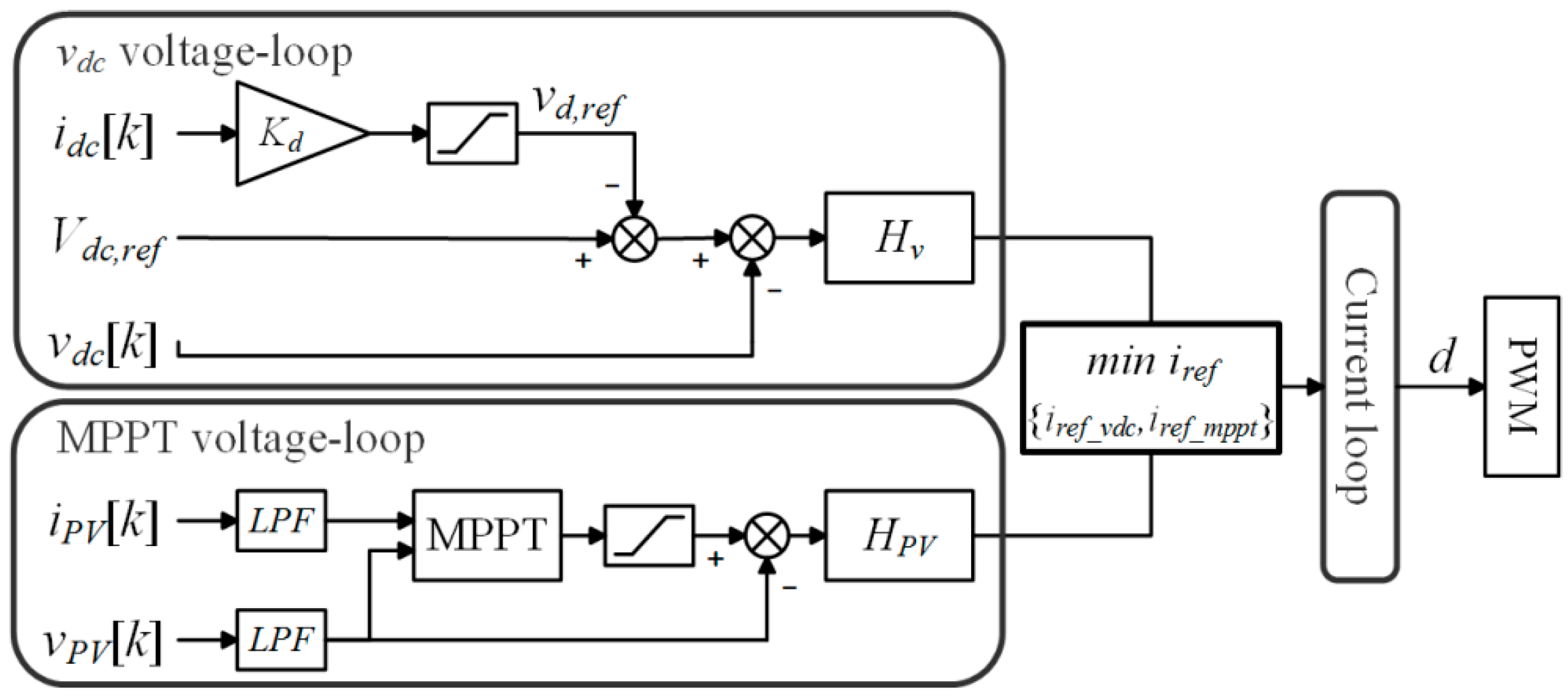
4.3. RC Local Controller

The RC’s local controller performs MPPT under normal conditions, and performs droop control of the dc voltage if off-MPPT is unavoidable. In Figure 9, the voltage-loops for both modes are operating continuously, and the current-loop references are generated. As seen in the VI curve in Figure 2c, the reference with the lower value is selected, which is expressed by min block in the diagram. The voltage-loop compensators for the two modes are designed based on two different models in which the control objectives are the regulation of vdc and vPV, respectively.

5. Experimental Results

To validate the proposed control strategy, a hybrid ac/dc microgrid was constructed in the laboratory as shown in Figure 10. Table 3 shows the specifications for this experimental setup, following the electric diagram shown in Figure 1. The ac and PV sources were replaced by a 1 kVA grid simulator and 1.8 kW PV simulator, respectively. The central controller was designed using Matlab/Simulink (MathWorks, Natick, MA, USA), and microcontrollers were used for the local controllers. The power dispatch command is transferred through controller area network (CAN) communication at 100 bps. In the following figures, vdc is the dc bus voltage, iload is the load current, and iG, iR, and iS are the output currents of GC, RC, and SC, respectively.

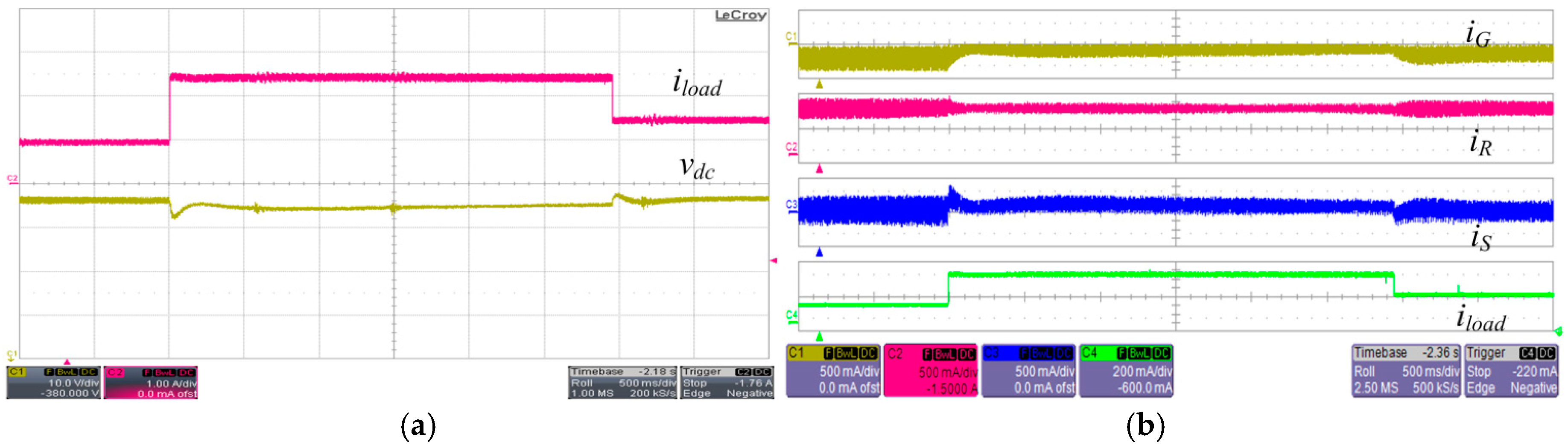
5.1. Single-Mode Operation

Figure 11a,b shows experimental results of load step change on State 111 with its operational description in Figure 3b. GC, SC, and RC are in the grid-connected mode, idle mode, and MPPT mode, respectively. During the load step changes from 400 W to 1 kW and from 1 kW to 600 W, with the RC output power remaining constant by performing MPPT. After each transition, the dc bus voltage fluctuates and then restores to the nominal voltage, 380 V. The dc bus voltage restoration is achieved by the slow PI controller in the GC’s local controller. It is seen that the SC’s output power remains zero, except for the transient period required to buffer the GC’s slow voltage regulation characteristic.
Figure 12 shows the experimental results of load step changes in State 211, in which the GC, SC, and RC are operated in the off-grid, idle, and MPPT modes, respectively. The dc load is changed from 0.4 kW to 1 kW, and from 1 kW to 0.6 kW, and the ac load is maintained at 450 W. In the absence of the grid power, the GC regulates the ac bus to the nominal voltage 220 Vrms, feeding the ac load. During the transitions, the dc bus voltage is regulated within 374–378 V because the dc bus voltage is not restored by the GC. The RC consistently performs MPPT, while the power balance condition is satisfied by the SC. Figure 12c,d show the detailed waveforms of the transition.

5.2. EMS Dispatch

Figure 13 depicts the reference dispatch of the EMS module in the central controller in fixed load consumption and PV generation. The system is operated in State 121, described in Figure 3c, in which the GC, SC, and RC are in the grid-connected, EMS, and MPPT modes, respectively. The central controller dispatches the power reference to SC, 300 W of charge, 300 W of discharge, and 0 W of output power. While the RC is in the MPPT mode, the SC regulates its output power to the given references.

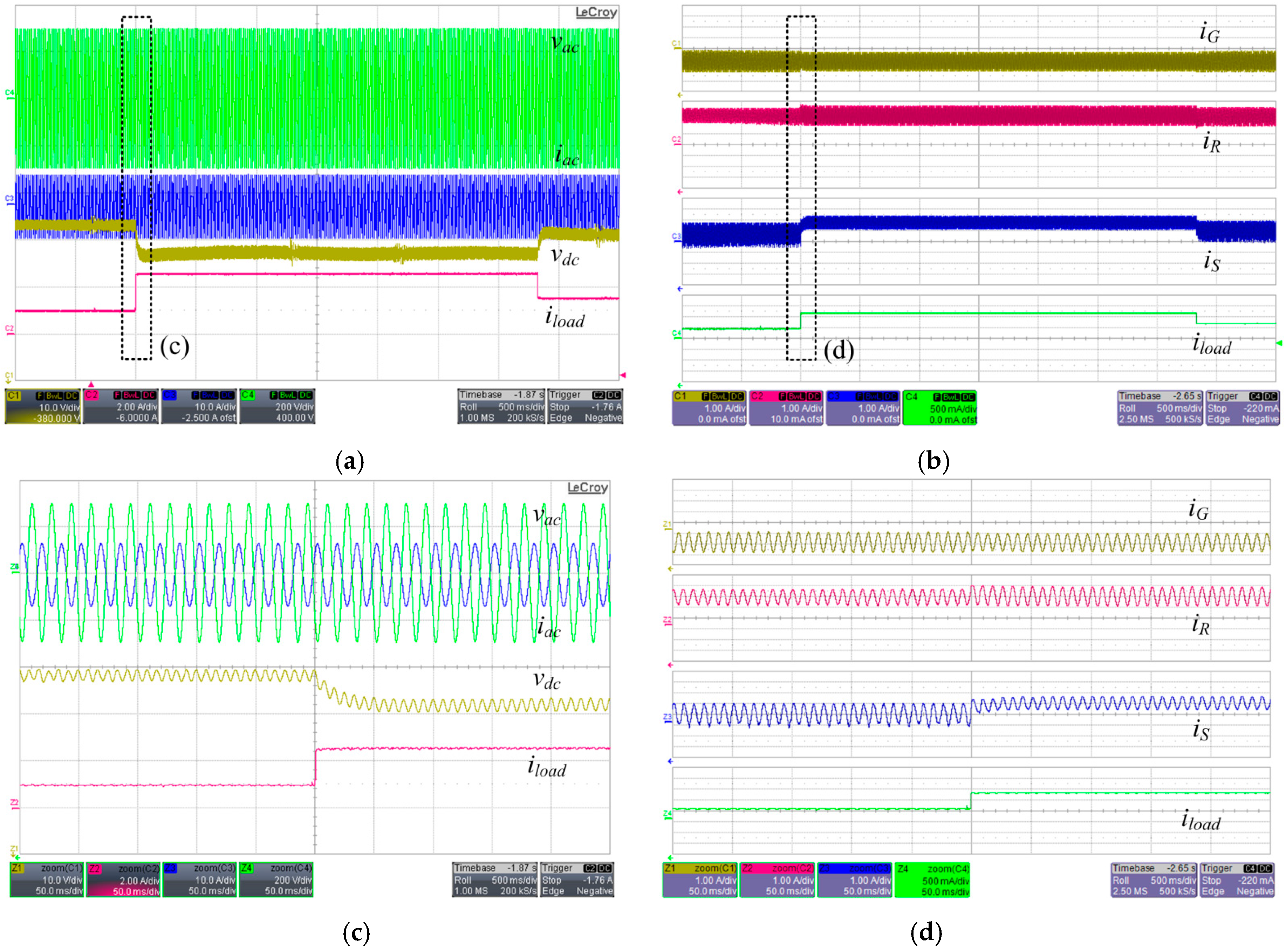
5.3. Mode Transitions

Figure 14 shows the experimentally determined waveforms for the mode transitions in the proposed control scheme. The GC’s state transitions according to the grid condition are shown, where vutil and iutil are the voltage and current of the utility grid power, respectively. When the grid voltage is interrupted, the GC’s mode is changed from the grid-connected mode to the off-grid mode. The GC feeds the ac loads with a sinusoidal ac voltage of 220 Vrms. After a few seconds, the grid voltage is restored, and the GC returns to the grid-connected mode.
In Figure 15, the SC’s operating mode switches from the idle mode to the EMS mode, and, accordingly, the state of the system is changed from State 111 to State 121. Before the transition, the SC participates in the droop control, with 0 W of steady-state output power. After the transition, the SC actively controls the output power of the ESS and charges the battery at the power reference, 500 W of charge, delivered from the central controller.
In Figure 16, the waveforms of the converters’ output currents and the dc voltage are depicted in the cases of failure of a unit. Figure 16a describes a GC failure event, and it is shown that the bus condition is maintained by the SC and RC. Whereas before the fault, the excessive power of the RC is exported to the grid through the GC, after the fault, the power charges the battery through the SC. The steady-state value of the dc voltage is increased because the dc voltage is not restored when the GC fails. In Figure 16b, whereas before the RC fault, the RC performs MPPT to supply a large portion of the total load, after the fault, the output power of the RC decreases to zero, and consequently, the GC and SC autonomously feed the loads without disrupting the operation of the system.
These experimental results verify that the proposed control strategy satisfies the control objectives discussed previously. The system maintains its bus quality under various fault conditions. The dc voltage is maintained within a limited range with the voltage restoration implemented through the GC. Moreover, efficient energy utilization is achieved through the low-speed communication. Furthermore, other control features, including the RC’s autonomous transition between MPPT and off-MPPT and the SC’s charge/discharge current limitation, are performed, although these results are not delivered in this paper.

6. Conclusions

This paper proposes a coordinated distributed control strategy for a hybrid ac/dc microgrid, considering several source characteristics. To achieve reliable operation and efficient management of energy, a two-level control structure is developed. Local controllers for the various sources are designed based on the droop method to optimally utilize the sources with high reliability. In the proposed scheme, the local controllers are linked to a central controller through a low-bandwidth communication device. The central controller executes EMS to optimally utilize the energy produced in the system. The proposed distributed control strategy is experimentally verified to demonstrate enhanced reliability and efficient operation.

Acknowledgments

This work was supported by the International Collaborative Energy Technology R&D Program of the Korea Institute of Energy Technology Evaluation and Planning (KETEP) granted financial resource from the Ministry of Trade, Industry & Energy, Korea (No. 20158530050130).

Author Contributions

The research presented in this paper was a collaborative effort among all authors. All authors developed the methodology, conducted the experiment, discussed results and wrote the paper.

Conflicts of Interest

The authors declare no conflict of interest.

References

  1. Yan, Y.; Qian, Y.; Sharif, H.; Tipper, D. A survey on smart grid communication infrastructures: Motivations, requirements and challenges. IEEE Commun. Surv. Tutor. 2013, 15, 5–20. [Google Scholar] [CrossRef] [Green Version]
  2. Xu, Z.; Yang, P.; Zeng, Z.; Peng, J.; Zhao, Z. Black start strategy for PV-ESS multi-microgrids with three-phase/single-phase architecture. Energies 2016, 9, 372. [Google Scholar] [CrossRef]
  3. Carrasco, J.M.; Franquelo, L.G.; Bialasiewicz, J.T.; Galván, E.; PortilloGuisado, R.C.; Prats, M.M.; León, J.I.; Moreno-Alfonso, N. Power-electronic systems for the grid integration of renewable energy sources: A survey. IEEE Trans. Ind. Electron. 2006, 53, 1002–1016. [Google Scholar] [CrossRef]
  4. Lasseter, R. Smart distribution: Coupled microgrids. Proc. IEEE 2011, 99, 1074–1082. [Google Scholar] [CrossRef]
  5. Arefifar, S.A.; Mohamed, Y.A.R.I. DG Mix, Reactive sources and energy storage units for optimizing microgrid reliability and supply security. IEEE Trans. Smart Grid 2014, 5, 1835–1844. [Google Scholar] [CrossRef]
  6. Loh, P.C.; Li, D.; Chai, Y.K.; Blaabjerg, F. Autonomous operation of hybrid microgrid with AC and DC subgrids. IEEE Trans. Power Electron. 2013, 28, 2214–2223. [Google Scholar] [CrossRef]
  7. Cho, B.H.; Choi, W.; Baek, J.B. Control of the dc distribution microgrid system. In Proceedings of the IEEE International Power Electronics Conference (IPEC), Hiroshima, Japan, 13–21 May 2014.
  8. Solanki, A.; Nasiri, A.; Bhavaraju, V.; Familiant, Y.L.; Fu, Q. A new framework for microgrid management: Virtual droop control. IEEE Trans. Smart Grid 2016, 7, 554–566. [Google Scholar] [CrossRef]
  9. Tan, K.T.; So, P.L.; Chu, Y.C.; Chen, M.Z.Q. A flexible AC distribution system device for a microgrid. IEEE Trans. Energy Convers. 2013, 28, 601–610. [Google Scholar] [CrossRef]
  10. Justo, J.J.; Mwasilu, F.; Ju, L.; Jung, J.W. AC-microgrids versus DC-microgrids with distributed energy resources: A review. Renew. Sustain. Energy Rev. 2013, 24, 387–405. [Google Scholar] [CrossRef]
  11. Yuan, C.; Haj-Ahmed, M.A.; Mahesh, S.I. Protection strategies for medium-voltage direct-current microgrid at a remote area mine site. IEEE Trans. Ind. Appl. 2015, 51, 2846–2853. [Google Scholar] [CrossRef]
  12. Bui, D.M.; Chen, S.L.; Wu, C.H.; Lien, K.Y.; Huang, C.H.; Jen, K.K. Review on protection coordination strategies and development of an effective protection coordination system for DC microgrid. In Proceedings of the 2014 IEEE Asia-Pacific Power and Energy Engineering Conference (APPEEC), Hong Kong, China, 7–10 December 2014; pp. 1–10.
  13. Wang, C.; Yang, X.; Wu, Z.; Che, Y.; Guo, L.; Zhang, S.; Liu, Y. A Highly integrated and reconfigurable microgrid testbed with hybrid distributed energy sources. IEEE Trans. Smart Grid 2016, 7, 451–459. [Google Scholar] [CrossRef]
  14. Hong, M.; Yu, X.; Yu, N.P.; Loparo, K.A. An energy scheduling algorithm supporting power quality management in commercial building microgrids. IEEE Trans. Smart Grid 2016, 7, 1044–1056. [Google Scholar] [CrossRef]
  15. Zhu, Y.; Zhuo, F.; Wang, F.; Liu, B.; Gou, R.; Zhao, Y. A virtual impedance optimization method for reactive power sharing in networked microgrid. IEEE Trans. Power Electron. 2016, 31, 2890–2904. [Google Scholar] [CrossRef]
  16. Vidyanandan, K.V.; Senroy, N. Frequency regulation in microgrid using wind—Fuel cell—Diesel generator. In Proceedings of the 2012 IEEE Power and Energy Society General Meeting (PESGM), San Diego, CA, USA, 22–26 July 2012; pp. 1–8.
  17. He, M.; Giesselmann, M. Reliability-constrained self-organization and energy management towards a resilient microgrid cluster. In Proceedings of the IEEE Innovative Smart Grid Technologies Conference (ISGT), Washington, DC, USA, 18–20 February 2015; pp. 1–5.
  18. Guerrero, J.M.; Chandorkar, M.; Lee, T.L.; Loh, P.C. Advanced control architectures for intelligent microgrids—Part I: Decentralized and hierarchical control. IEEE Trans. Ind. Electron. 2013, 60, 1254–1262. [Google Scholar] [CrossRef]
  19. Karlsson, P.; Svensson, J. DC bus voltage control for a distributed power system. IEEE Trans. Power Electron. 2003, 18, 1405–1412. [Google Scholar] [CrossRef]
  20. Rocabert, J.; Luna, A.; Blaabjerg, F.; Rodri, X.; Guez, P. Control of power converters in AC microgrids. IEEE Trans. Power Electron. 2012, 27, 4734–4749. [Google Scholar] [CrossRef]
  21. Guerrero, J.M.; Vasquez, J.C.; Matas, J.; Vicuña, L.G.; Castilla, M. Hierarchical control of droop-controlled AC and DC microgrids—A general approach toward standardization. IEEE Trans. Ind. Electron. 2011, 58, 158–172. [Google Scholar] [CrossRef]
  22. Choi, W.; Baek, J.B.; Cho, B.H. Control design of coordinated droop control for hybrid AC/DC microgrid considering distributed generation characteristics. In Proceedings of the IEEE Energy Conversion Congress and Exposition (ECCE), Pittsburgh, PA, USA, 14–18 September 2014; pp. 4276–4281.
  23. Farhadi, M.; Mohammed, O. Adaptive energy management in redundant hybrid DC microgrid for pulse load mitigation. IEEE Trans. Smart Grid 2015, 6, 54–62. [Google Scholar] [CrossRef]
  24. Dragičević, T.; Guerrero, J.M.; Vasquez, J.C.; Škrlec, D. Supervisory control of an adaptive-droop regulated DC microgrid with battery management capability. IEEE Trans. Power Electron. 2014, 29, 695–706. [Google Scholar] [CrossRef]
  25. Aymen, C.; Rashad, M.K.; Ridha, A.; Ken, N. Multiobjective intelligent energy management for a microgrid. IEEE Trans. Ind. Electron. 2013, 60, 1688–1699. [Google Scholar]
  26. Li, F.; Xie, K.; Yang, J. Optimization and analysis of a hybrid energy storage system in a small-scale standalone microgrid for remote area power supply (RAPS). Energies 2015, 8, 4802–4826. [Google Scholar] [CrossRef]
Figure 1. System diagram of hybrid ac/dc microgrid with communication links.
Energies 10 00373 g001
Figure 2. Droop characteristics in VI curves of (a) grid-interfaced converter (GC); (b) storage converter (SC); and (c) renewable energy source (RES) converter (RC).
Energies 10 00373 g002
Figure 3. VI curves of the converters for various operation examples. (a) Voltage reference change of GC after relevant transition; (b) voltage reference change of SC by energy management system (EMS); (c) failure of GC; and (d) change of photovoltaic (PV) generating power.
Energies 10 00373 g003
Figure 4. VI curves and the operating points at State 111.
Energies 10 00373 g004
Figure 5. EMS optimization results with various conditions. (a) Power profile with fixed price; (b) energy profile with fixed price; (c) power profile with variable price; (d) energy profile with variable price; and (e) optimization result of a calculation executed 6 days ahead of time, with variable price.
Energies 10 00373 g005
Figure 6. Control diagram of GC local controller.
Energies 10 00373 g006
Figure 7. Voltage-loop reference on VI curve of GC local controller.
Energies 10 00373 g007
Figure 8. Control diagram of SC local controller.
Energies 10 00373 g008
Figure 9. Control diagram of RC local controller.
Energies 10 00373 g009
Figure 10. Experimental setup.
Energies 10 00373 g010
Figure 11. Experimental waveforms of load step change on State 111 (0.4 kW to 1 kW to 0.6 kW). (a) Load current and dc bus voltage; and (b) output current.
Energies 10 00373 g011
Figure 12. Experimental waveforms of load step change on State 211. (a) Bus voltage and current; (b) output current; (c) zoomed-in waveform of (a); and (d) zoomed-in waveform of (b).
Energies 10 00373 g012
Figure 13. Experimental waveforms of EMS dispatch on State 121.
Energies 10 00373 g013
Figure 14. State transition of GC according to the grid condition. (a) Transition of GC; (b) zoomed-in waveforms during transition of grid-connected to off-grid; and (c) zoomed-in waveforms during transition of off-grid to grid-connected.
Energies 10 00373 g014
Figure 15. State transition of SC between idle mode and EMS mode.
Energies 10 00373 g015
Figure 16. Failure modes of (a) GC; and (b) RC.
Energies 10 00373 g016
Table 1. Operating modes of converters.
StateGrid-Interfaced Converter (GC)Storage Converter (SC)RES Converter (RC)
1Grid-connected: VdcIdle: VdcMPPT: PPV
2Off-grid: VacEMS: PESSOff-MPPT: Vdc
3FailFailFail
Table 2. Communication of the central controller. SOC: state of charge.
TargetTransmitReceive
GCProtectionMeasurements, Vdc restoration
SCProtection, EMS, Mode selectionMeasurements, SOC, Vocv
RCProtectionMeasurements
Table 3. Specifications of experiment set-up.
ComponentRating
AC sourceGrid simulator 1 kVA
PV sourceOCV 150 V/SCC 14 A/MPP 1800 W
Battery4.2–2.7 V/31 Ah/Li-polymer cell/56S1P
Grid converter1 kW/18 kHz
Storage converter2 kW/50 kHz
RES converter2 kW/50 kHz
DC loadElectric load/1 kW
AC loadResistive load/108 Ω
Central controllerMatlab/Simulink
Local controllerTexas Instruments TMS320F28335 (Dallas, TX, USA)

