1. Introduction
There have been rapid developments and significant momentum in the use of offshore wind farms in the recent years, because wind power provides a source of clean and renewable energy [
1,
2,
3]. Voltage source converter (VSC)-based high voltage direct current (HVDC) systems have increased in popularity because VSC-HVDC systems are economical for long-distance bulk power transmission. Unlike high-voltage alternating-current (HVAC) systems, the VSC-HVDC transmission system capacity is not limited by the capacitive charging current. Moreover, the offshore wind farm can be decoupled from the onshore grid in this system, and the active and reactive power can be controlled independently at both ends [
4,
5,
6].
Fully-rated converter (FRC)-based wind turbines (WTs) with a permanent magnet synchronous generator (PMSG) have a wide speed control range, good reactive power support, and fault-ride-through capability [
7], and offshore wind farms incorporating FRC-WTs and VSC-HVDC connections are likely to play an important role in the future of wind energy utilization [
8,
9,
10].
The use of offshore wind farms has resulted in some technical challenges, including fault detection, isolation, and restoration (FDIR) methods for offshore wind farms. In the offshore collector grid, fault currents are mainly determined by FRC-WTs and HVDC controls in the case of a fault [
11]. Offshore wind farms with a VSC-HVDC connection will have different fault responses compared to conventional alternating current (AC) systems. The fault current capability of an FRC-WT is usually limited to its rated current or slightly above its rated current, and is determined by the short-time current-carrying capacity of the semiconductor switches. A low fault current level will be insufficient to activate conventional over-current protection schemes in the inverter-dominated AC-networks of offshore wind farms [
12,
13,
14]. Here, we consider an ungrounded configuration for detecting single-line-to-ground (SLG) faults in offshore wind farms. The fault ride-through capability of FRC-WTs in an offshore wind farm will be considered for an offshore wind farm protection scheme.
Faults in an offshore wind farm should be detected and isolated sufficiently quickly that the FRC-WTs can operate stably through the fault [
15]. SLG faults in ungrounded offshore wind farms do not lead to large currents, however, during an SLG fault, an ungrounded offshore wind farm is subject to a high and destructive transient overvoltage, which is potentially hazardous to equipment [
16]. Thus, locating and isolating the SLG fault is important in an ungrounded offshore wind farm.
There are many feeder protection methods for offshore wind farms with FRC-WTs, such as overcurrent protection, methods based on directional power and peak current, or impedance protection. The author of [
17] presented a method based on the coordination of over-current relays. However, offline analysis is required to obtain approximate values for the fault current levels under different operating conditions. If the system topology is changed, the fault current levels should be recalculated. The authors of [
18] proposed a protection method based on peak current and directional power; the protection system can detect the faulted feeder and faulted feeder section. However, this method can only respond to a three-phase fault. The authors of [
19] proposed an offshore wind farm feeder protection strategy based on impedance. The impedance protection system was designed using two zones, encircling the feeder impedance and the load area. It has the advantage of selectively having high sensitivity to fault currents and low sensitivity to load currents. However, the impedance characteristic for both zones should be of a quadrilateral shape, with some time delay.
This paper analyzes the behavior of an ungrounded offshore wind farm in the case of an SLG fault at different locations to evaluate the feasibility of effective fault detection strategies in the grid. Various protection methods relying on communication have been described in the literature [
20,
21]. In conventional ungrounded distribution feeders, there is only one source to supply fault currents. Several techniques have been proposed for locating SLG faults in conventional ungrounded distribution feeders, such as signal injection [
22], traveling-wave [
23], and phasor-based [
24] methods. However, in ungrounded offshore wind farms, there are two sources: HVDC and FRC-WTs. Therefore, it is difficult to use conventional methods for locating SLG faults in ungrounded offshore wind farms. The proposed method can locate SLG faults in ungrounded offshore wind farms without the installation of expensive synchronization devices. First, a collector bus protection detects the fault status and then a unit protection detects the fault direction. Finally, the fault section is identified by coordination of unit protection and collector bus protection. The proposed method, therefore, requires communication only when there is an event in the system, and time synchronization is not required.
The remainder of the paper is organized as follows.
Section 2 gives an overview of the major protection issues in offshore wind farms with FRC-WTs,
Section 3 describes the proposed protection method for an offshore wind farm with FRC-WTs,
Section 4 presents simulation results, and conclusions are provided in
Section 5.
2. Fault Characteristics in an Offshore Wind Farm with FRC-WTs
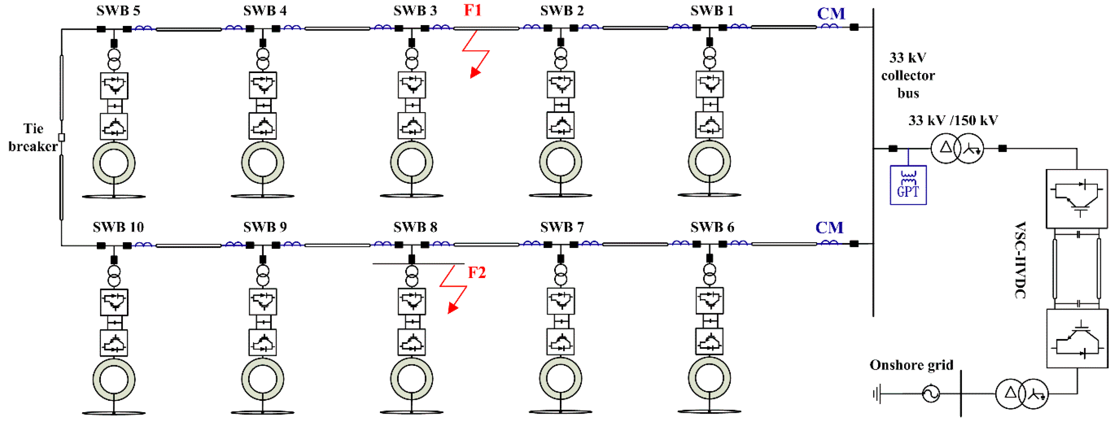
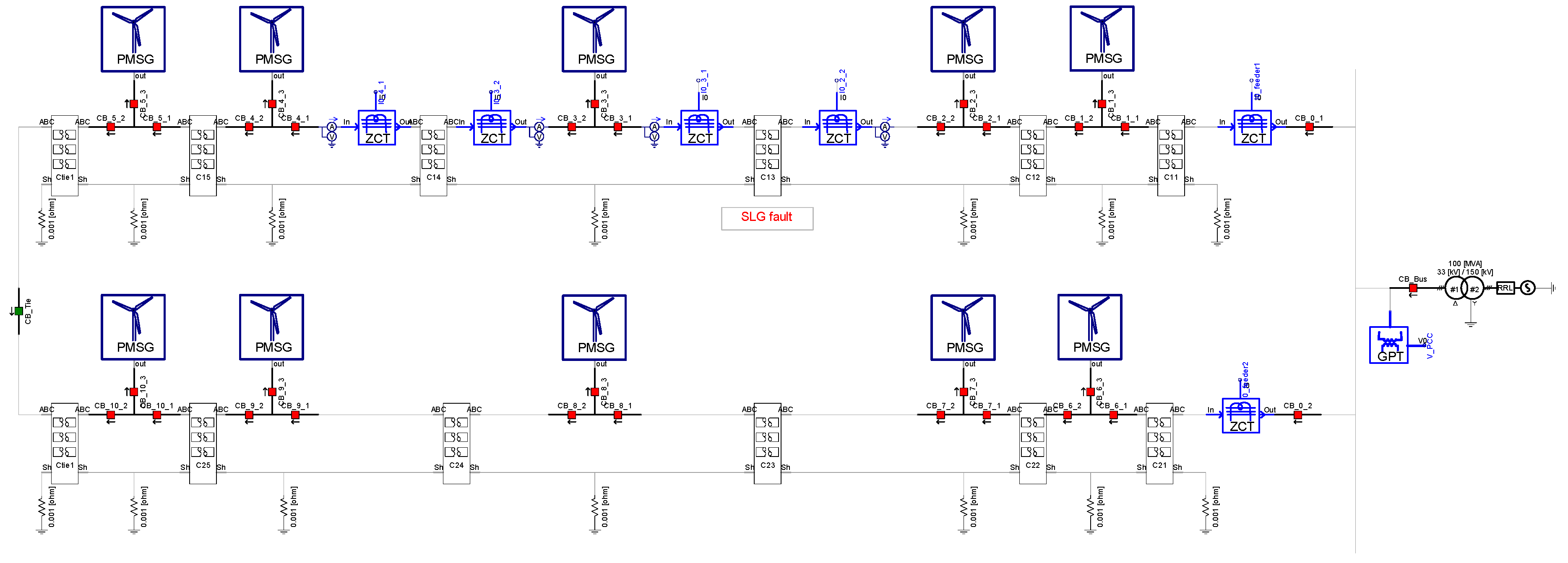
Figure 1 shows the system being studied. It consists of ten FRC-WTs equally distributed and separated into two feeders. The offshore wind farm is interconnected to a VSC-HVDC transmission system via a Y/∆ offshore converter transformer. The offshore converter transformer has a nominal voltage ratio of 33/150 kV. The 150-kV terminals of the converter transformer serve the high voltage (HV) system, and this HV system enables the suitable operation of the VSC-HVDC. The 33-kV terminals of the converter transformer, consisting of delta connection winding, serve as the collector bus, and the offshore wind farm is, therefore, an ungrounded system [
25,
26,
27].
Two medium-voltage (MV) feeders are connected to the collector bus, with five switchboards (SWBs) on each feeder and three circuit breakers (CBs) installed at each SWB. The FRC-WT is connected to the SWB via a step-up transformer. The FRC-WT side of the step-up transformer is a wye connection winding and the collector bus side is a delta connection winding. There are five MW FRC-WTs on each feeder and, therefore, the total capacity of one feeder is 25 MW. Two feeder strings are connected to the MV collector bus, and the rated capacity of the offshore wind farm is, therefore, 50 MW. The limited number of FRC-WTs provides acceptable computation times in simulations and can provide some insight into the behavior of ungrounded offshore wind farms with FRC-WTs under fault. As shown in
Figure 1, a feeder fault occurred at position 1 and a FRC-WT branch fault occurred at position 2.
At the collector bus, a ground potential transformer (GPT) is used to measure the zero-sequence voltage and create an artificial ground, because delta-connected systems have no wye point available for connection to ground. The wye-connected primary windings of the GPT are grounded solidly with a current-limiting resistor (CLR) connected across the broken delta of the tertiary windings. The CLR
Rcl connected at the tertiary can be transformed into the equivalent grounding resistance
RCL connected at the primary:
where
n is the GPT turns ratio. Because the CLR has the effect of providing very high-resistance grounding on ungrounded systems with a few tens of kilo-ohms, it introduces few side-effects. SLG faults produce zero-sequence currents that have extremely small magnitudes compared to phase currents. Because it is almost impossible to calculate zero-sequence currents from phase currents, a zero-sequence current transformer (ZCT) is used. The ZCT had a ratio of 200 mA/1.5 mA, which is the typical ratio used in South Korea.
Each SWB has two current transformer modules (CMs). Each CM can measure the zero-sequence current and positive-sequence current flow through the SWB.
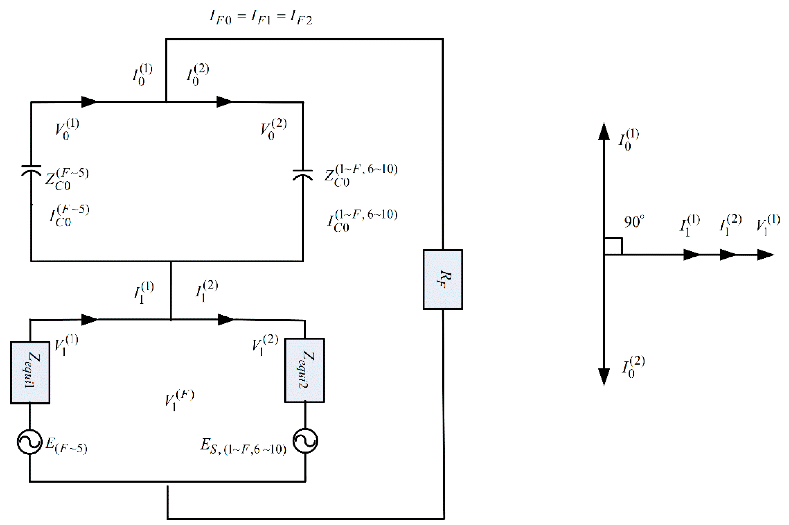
Figure 2 shows the sequence networks and their interconnections for the SLG fault at position 1 shown in
Figure 1 using the following notation [
28,
29]:
: line impedance from the mth node to the nth node,
: line-to-ground capacitive impedance from the mth node to the nth node,
: FRC-WT source impedance including the step-up transformer,
: HVDC source impedance including the offshore converter transformer,
: current from the mth node to the next node radially,
: fault current,
: voltage at the mth node,
: FRC-WT source from the mth node to the nth node,
: HVDC source,
: fault resistance.
The term k = 0, 1 and 2 denotes the zero, positive, and negative sequence, respectively.
Because the magnitude of the zero-sequence impedance of an ungrounded system is very large, the negative-sequence impedance can be ignored without significant loss of accuracy when considering SLG faults. This leads to the simplified zero-sequence network and the corresponding phasor diagram shown in
Figure 3.
The best solution for operating a wind farm is to keep a constant power factor close to 1. Assuming that a wind farm is operated at a constant power factor of 1, the phase angle difference between
and
becomes
. Since
and
are equal in the positive-sequence network shown in
Figure 3, the phase angle difference between
and
is almost
. In the zero-sequence network,
lags
by
, and
leads
by
due to capacitive reactance. Since the phase angle difference between
and
is
,
leads
by
. In addition,
is equal to the inverse of
. Therefore,
leads
by
, and
lags
by
. Consequently, while the zero-sequence current on the left side of the fault leads the positive sequence current by
, the zero-sequence current on the right side of the fault lags the positive sequence current by
.
3. Proposed Protection Method for SLG Faults in an Offshore Wind Farm
Similar to the microgrid protection method in [
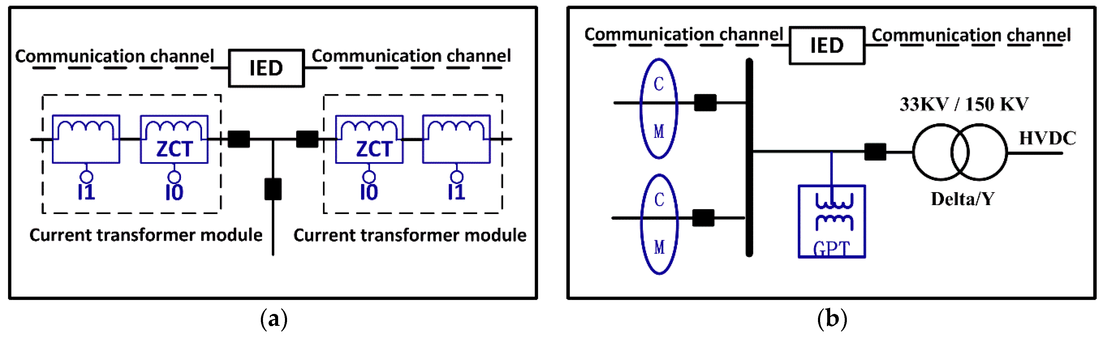
30], the proposed protection method utilizes both unit and collector bus protection, as shown in
Figure 4. The main difference between the microgrid and proposed protection methods is the identification of sections in fault. In the case of the microgrid protection method, a lateral branch is required for each node, and three ZCTs are used to determine the flow direction of zero sequence currents. For the proposed protection method, no lateral branch is required and only two ZCTs are used to determine the flow direction of zero sequence currents.
Figure 4a presents the proposed FRC-WT unit protection, which consists of an intelligent electronic device (IED) situated locally (at the SWB) that is able to detect the fault and send a required action at the hardware level. Three wye-connected CBs are installed in the FRC-WT connection point and controlled by the IED. The breakers can be used to isolate the fault section. The IED can obtain the required information from the two current transformers and two ZCTs installed at the left and right sides of the SWB. The three-phase currents from two adjacent measurement points are exchanged using the communication channel. Each unit protection collects the unsynchronized current phasors from two adjacent nodes and synchronizes the current phasors by aligning the positive-sequence current from the adjacent nodes to the same phase, and then the phases of the zero-sequence currents from the two adjacent measurement points are compared.
As shown in
Figure 4b, the collector bus protection system can obtain the required information from the GPT and the two ZCTs installed at the end of the feeder. The two breakers installed at the end of each feeder are controlled by the collector bus protection and can be used to isolate the fault section. Time synchronization is not required, and ground potential transformers (GPTs) are also not required at every SWB. It is difficult to install GPT at every node in an offshore wind farm.
In conventional methods, all phasors need to be synchronized using a global positioning system (GPS) because they are collected from each node with a different time reference. In the proposed method, only positive-sequence phasors need to be synchronized between unit protections and bus protection. Synchronization is achieved using phase compensation based on the characteristics of the ungrounded offshore wind farm. Therefore, additional GPS-receiving equipment is not required.
Figure 5 shows the communication channels between current transformer modules and IEDs. IEDs are usually equipped with communication functionality, such as the International Electrotechnical Commission (IEC) 61850. Each IED will exchange the three-phase current and zero-sequence current signals with its upstream and downstream IED. The IED will synchronize the current by aligning the positive-sequence current angle. The zero-sequence current angle is then compared and the faulted feeder section can be located by the coordination of IEDs. If fault F1 occurs, the IED at SWB3 will detect that the zero-sequence current leads the positive sequence at CM2, and the IED at SWB2 will detect that the zero-sequence current lags the positive sequence at CM1. This identifies an SLG fault in the cable between CM1 and CM2. If fault F2 occurs, the IED at SWB3 will detect that the zero-sequence current leads the positive sequence at CM3, and will also detect that the zero-sequence current lags the positive sequence at CM2. This identifies an SLG fault in the FRC-WT branch of SWB3. In the case of a feeder fault, two SWBs near the fault position can locate the fault section, and in the case of an FRC-WT branch fault, two current transformer modules installed on the left and right sides of the SWB can indicate the fault position by comparing the sequence angle difference within the SWB.
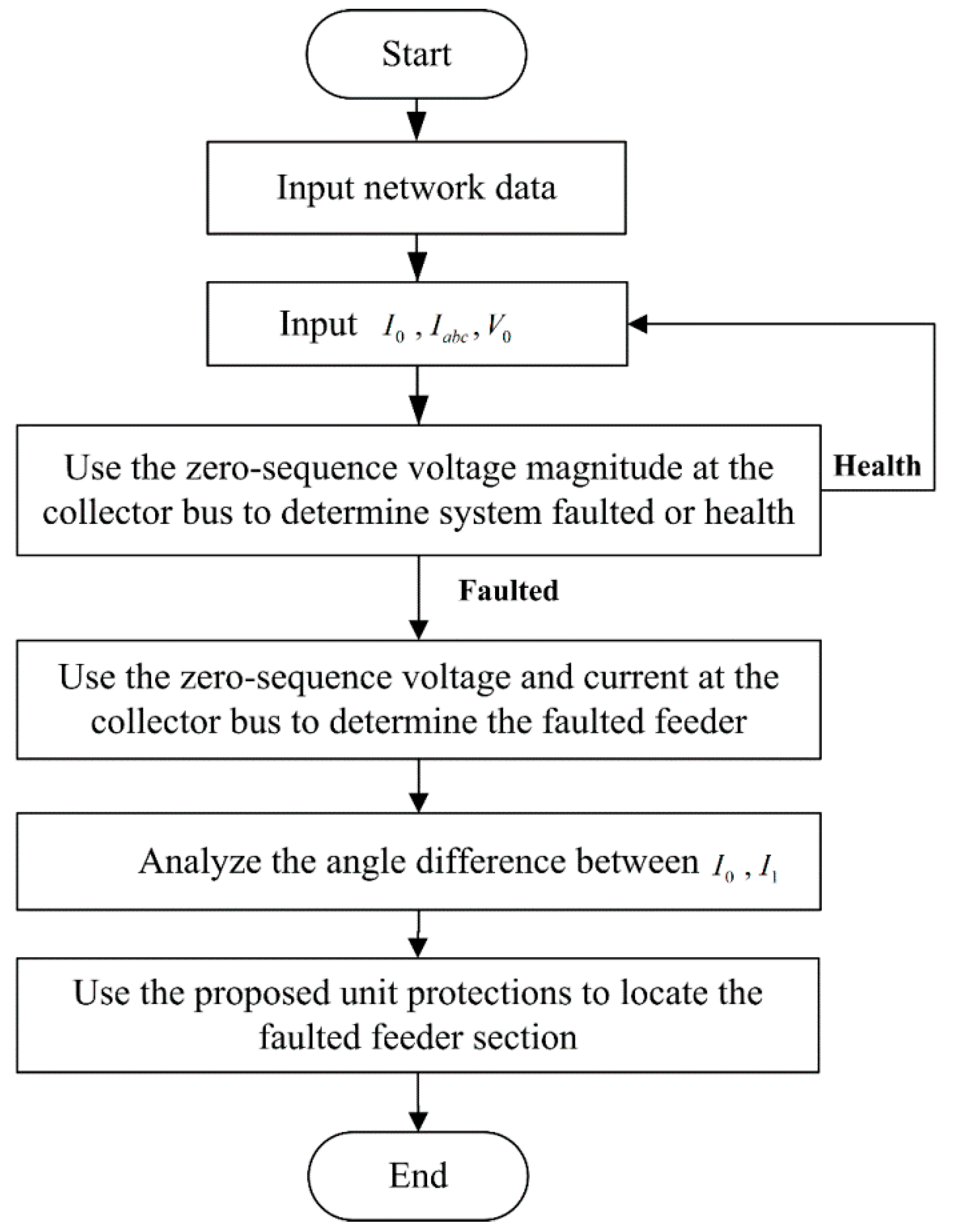
If an SLG fault occurs in the offshore wind farm, the IED installed at the 33-kV collector bus will detect that the zero-sequence voltage magnitude exceeds the pre-set value, which enables detection of the fault status. The collector bus protection will detect the faulted feeder from the angle difference between the zero-sequence voltage and the zero-sequence current. In the faulted feeder, the zero-sequence current will lag the zero-sequence voltage by
to
, whereas in a healthy feeder, the zero sequence current will lead the zero-sequence voltage by
[
30]. The collector bus protection method is shown in
Figure 6.
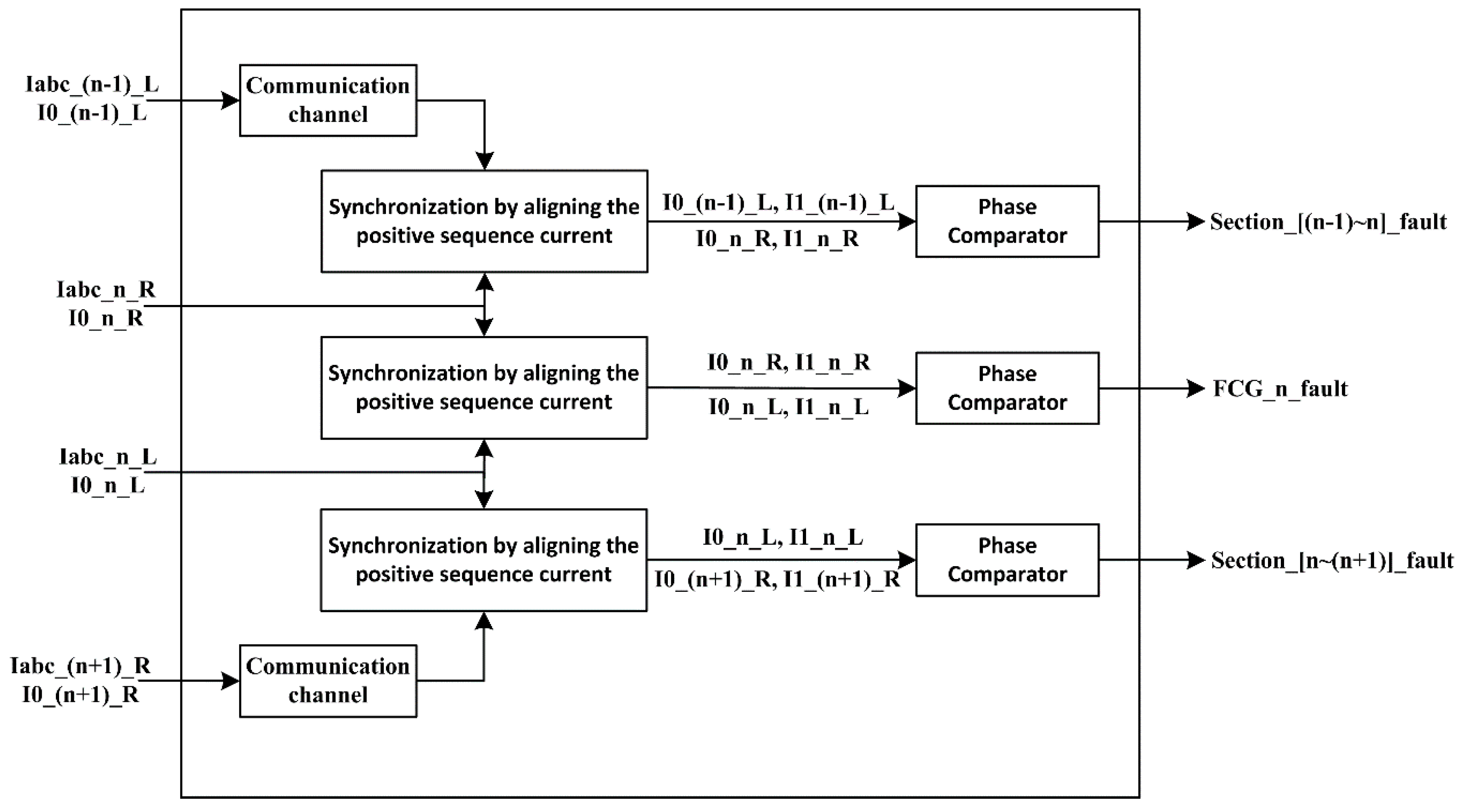
After the faulted feeder is detected, the fault status signal can be sent to IEDs in the faulted feeder by the communication channel, and IEDs installed in the faulted feeder will process the positive-sequence and the zero-sequence current signals. Each unit protection collects the unsynchronized current phasors from two CMs in the local SWB, the left side of the upstream SWB, and the right side of the downstream SWB, and the IED can synchronize these by aligning the adjacent positive-sequence current to the same phase angle. The faulted section is identified by comparing the phase angles of the synchronized zero-sequence currents. The FRC-WT unit protection method is shown in
Figure 7. In the block diagram of unit protection, Iabc_n_L denotes the three-phase current at the left side of the
nth SWB, Iabc_n_R denotes the three-phase current at the right side of the
nth SWB, and section [(n − 1)~n] denotes the section between SWB (n − 1) and SWB (n).
The faulted feeder and faulted section can then be located by the coordination of IEDs. The proposed fault detection and location scheme is shown in
Figure 8.
With regard to the fault section isolation method, two scenarios were explored with different fault positions: feeder fault and FRC-WT branch fault in an offshore wind farm. The proposed unit protection will disconnect the smallest possible portion of the collector feeder in the case of a feeder SLG fault. The CB will open if the tripping condition is reached. As shown in
Figure 9, in the case of the feeder fault F1, the unit protection installed at SWB3 and the unit protection installed at SWB 2 detect the fault within the cable between the SWB2 and SWB3, and CB3.2 and CB2.1 will open to isolate the fault section. If there is a tie-breaker and cable between feeder 1 and feeder 2, then SWB3, SWB4, and SWB5 can be transferred to feeder 2 and resupplied via SWB10. The proposed protection method allows selective operation of CBs. The unit protection will send a trip signal to the central breaker of SWB in the case of an FRC-WT branch fault F2. Once the FRC-WT fault is detected, the FRC-WT should be cut off from the offshore wind farm. CB8.3 will open to isolate the fault section, while other parts of the offshore wind farm will continue to work. Once the fault is cleared, the FRC-WT can be reconnected to the offshore wind farm.
Because the proposed method relies on communication channels, communication failure management is critical for system protection, and backup protection should be considered to cope with communication failure. Collector bus protection will be operated after a given time, as a backup in the case of communication failure. Using this method, the protection system will maintain operation of an offshore wind farm with FRC-WTs.
4. Case Study
To investigate the effectiveness of the protection method, an offshore wind farm was simulated using Power system computer-aided design (PSCAD)/ electromagnetic transients including direct current (EMTDC), as shown in
Figure 10.
Individual wind turbine generators and cables between wind turbines were modeled, and the onshore grid and VSC-HVDC was represented by a simple Thevenin’s equivalent. The 150-kV bus supplied the Y/∆ offshore converter transformer, which had a nominal voltage ratio of 33/150 kV. Two feeders were connected to the 33-kV terminals of the converter transformer, with five 5-MW FRC-WTs on each feeder. The distance between two adjacent FRC-WTs was 1 km, and GPT was modeled in the collector bus. The current transformer modules were modeled in SWB2, SWB3, SWB4, and the collector bus.
Table 1 lists the parameters for the offshore wind farm. The distance between two adjacent feeders was 1.5 km, and 33-kV cross-linked polyethylene (XLPE) submarine cables were used to connect the FRC-WTs. The submarine cables between each wind turbine were connected on the bottom of each wind turbine where the sheaths of the cables were grounded [
31].
Table 2 and
Table 3 list the cable parameters [
6] and the fully-rated converter wind turbine parameters [
32] used in the simulations, respectively.
As shown in
Figure 11, initially the offshore wind farm was assumed to be de-energized. From the start of the simulation to a time of 2 s, the wind speed was kept constant at 7 m/s, which is the cut-in wind speed for the FRC-WT with PMSG studied in this paper. At 2 s, the wind speed was ramped up from 7 m/s, and the ramping of wind speed lead to ramping of the active power output. At 7 s, the wind speed reached 12 m/s and was kept constant, which is the rated wind speed for the FRC-WT with PMSG. The active power output of the offshore wind farm also ramped up to the maximum power level [
33,
34,
35,
36,
37].
An SLG fault between the cable, the sheath, and the ground was simulated on the 33-kV collector feeder 1, with a fault impedance of 0.01 Ω. The fault occurred at position 1, as shown in
Figure 1. The voltage and current signals were pre-conditioned using a second-order Butterworth low-pass filter with a cutoff frequency of 360 Hz to prevent aliasing errors. The sampling frequency was set to 3840 Hz (64 samples per cycle in 60-Hz systems) and a discrete Fourier transform (DFT) was used to estimate the phasors.
As shown in
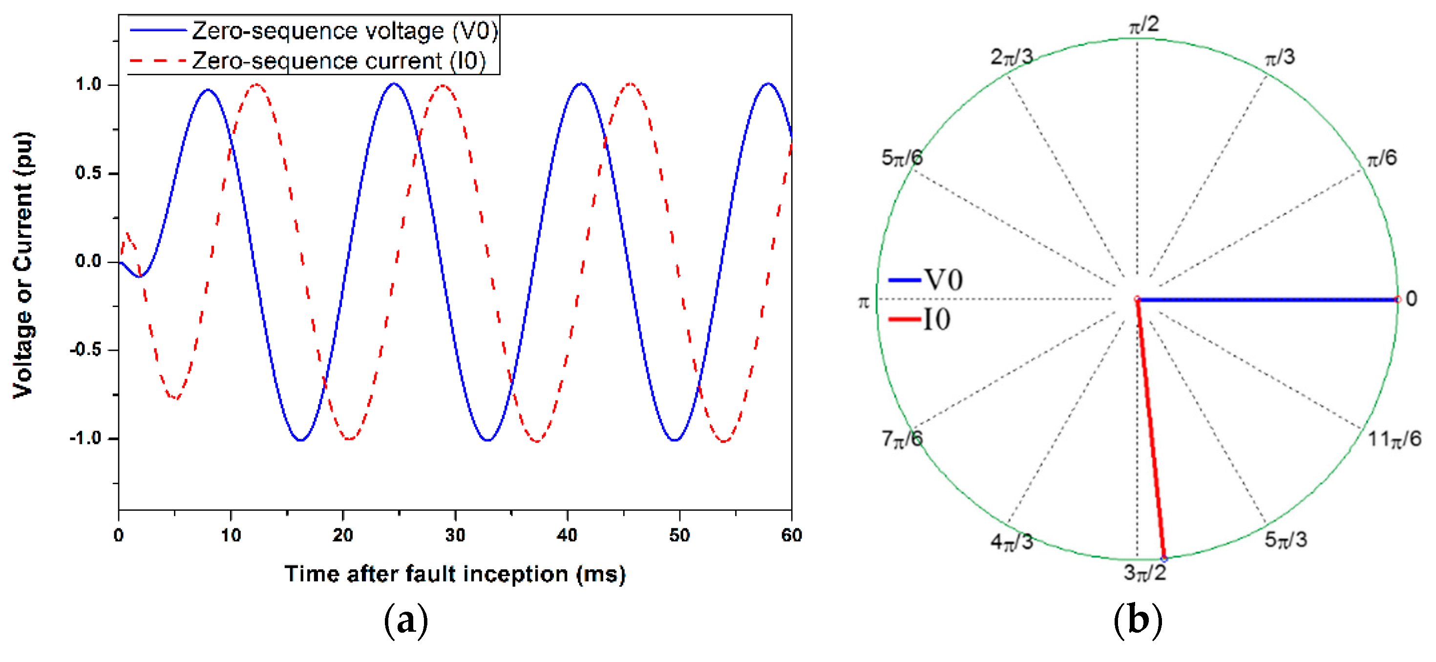
Figure 12, the zero-sequence current at feeder 1 lagged the zero-sequence voltage at the collector bus. The zero-sequence angle difference dropped to between 60° and 90° in feeder 1. This angle difference indicated that there was an SLG fault at feeder 1. In the case of an SLG fault, the faulted phase may be detected readily using the phase voltage at the collector bus.
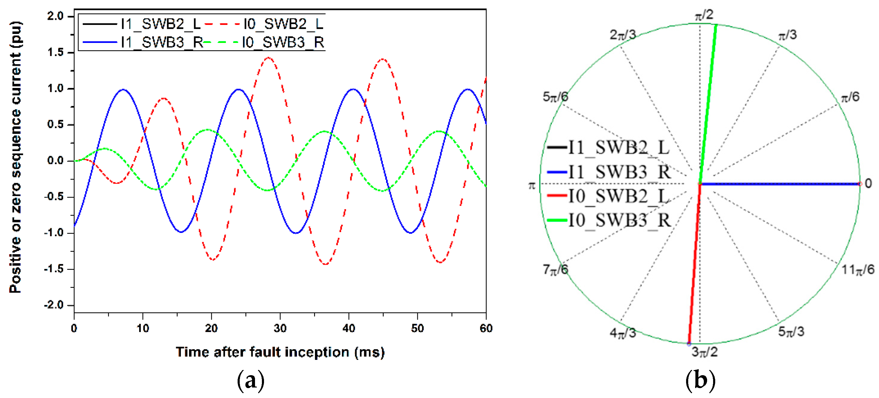
As shown in
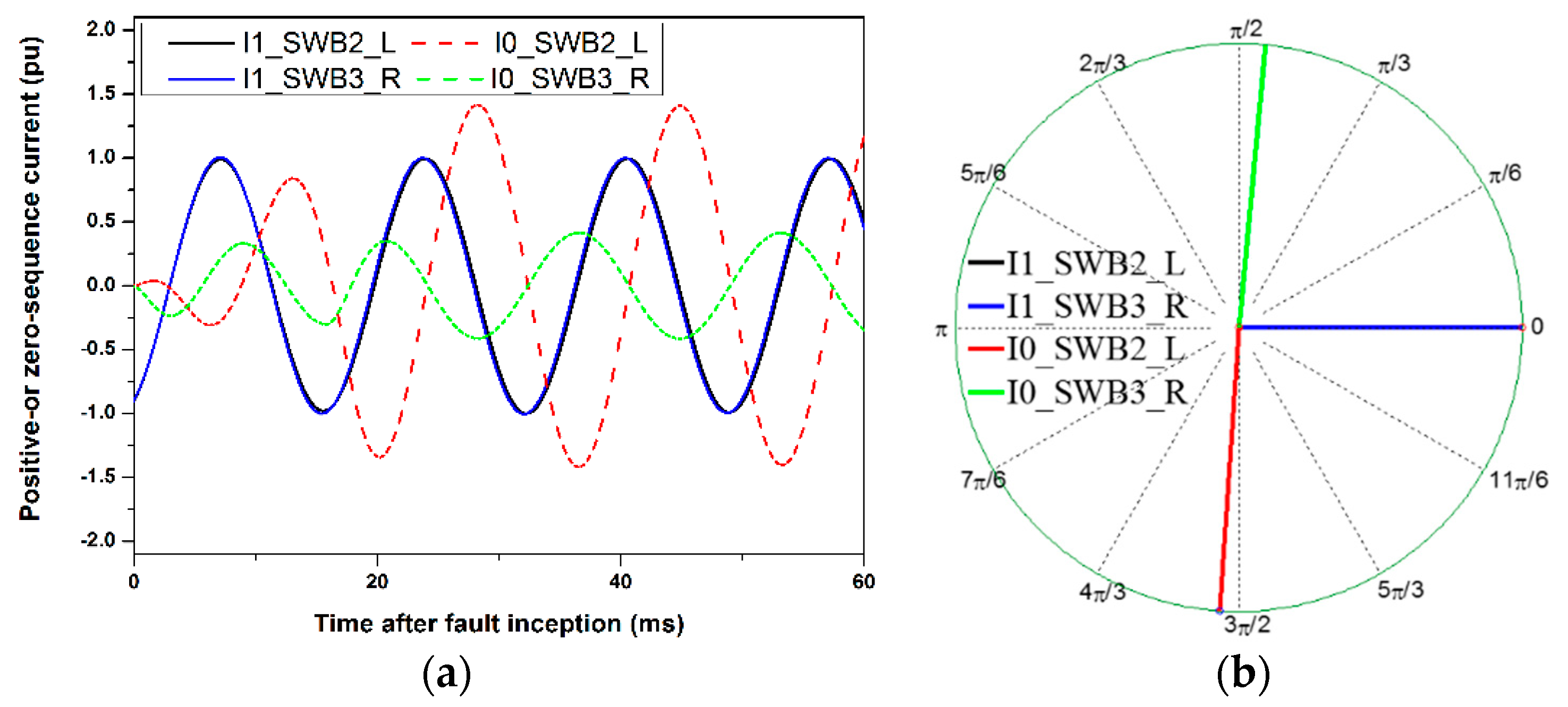
Figure 13, the unsynchronized phasors from the left side of SWB2 and the right side of SWB3 were approximately synchronized by aligning the positive-sequence current phasors. The positive-sequence current and the zero-sequence current at the left side of SWB2 and the right side of SWB3 indicated that an SLG fault occurred. The zero-sequence current leads the positive-sequence current at the right side of SWB3, indicating that an SLG fault occurred at the right side of the measurement point. The figure also shows that the zero-sequence current lagged the positive-sequence current at the left side of SWB2, indicating that an SLG fault occurred at the left side of SWB2. The fault section can, therefore, be located. The simulation results show that there is an SLG fault between SWB2 and SWB3, and the faulted section can be identified by comparing the angle difference between the positive-sequence and zero-sequence current phasors.
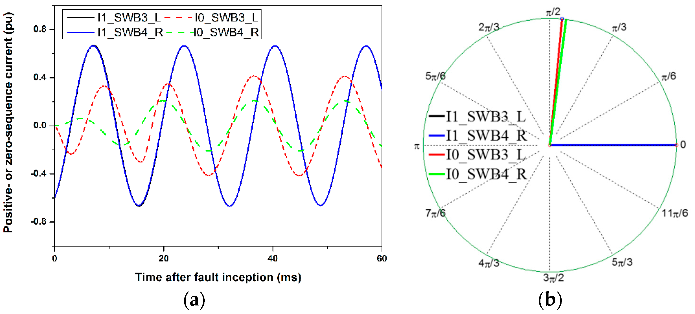
As shown in
Figure 14, the unsynchronized phasors from the left side of SWB3 and the right side of SWB4 were approximately synchronized by aligning the positive-sequence current phasors. The zero-sequence current led the positive-sequence current at the right sides of SWB4 and SWB3. This indicates that an SLG fault occurred at the right side of SWB3. The two zero-sequence angles were in the same direction. The simulation results show that there was no SLG fault between SWB3 and SWB4. Similar trends were found at the right side of SWB2 and the left side of SWB1.
The A phase-sheath fault was simulated with a fault resistance of 0.02 Ω at the same position. The simulation results are shown in
Figure 15, and indicate that the proposed method can successfully detect a single phase-sheath fault.
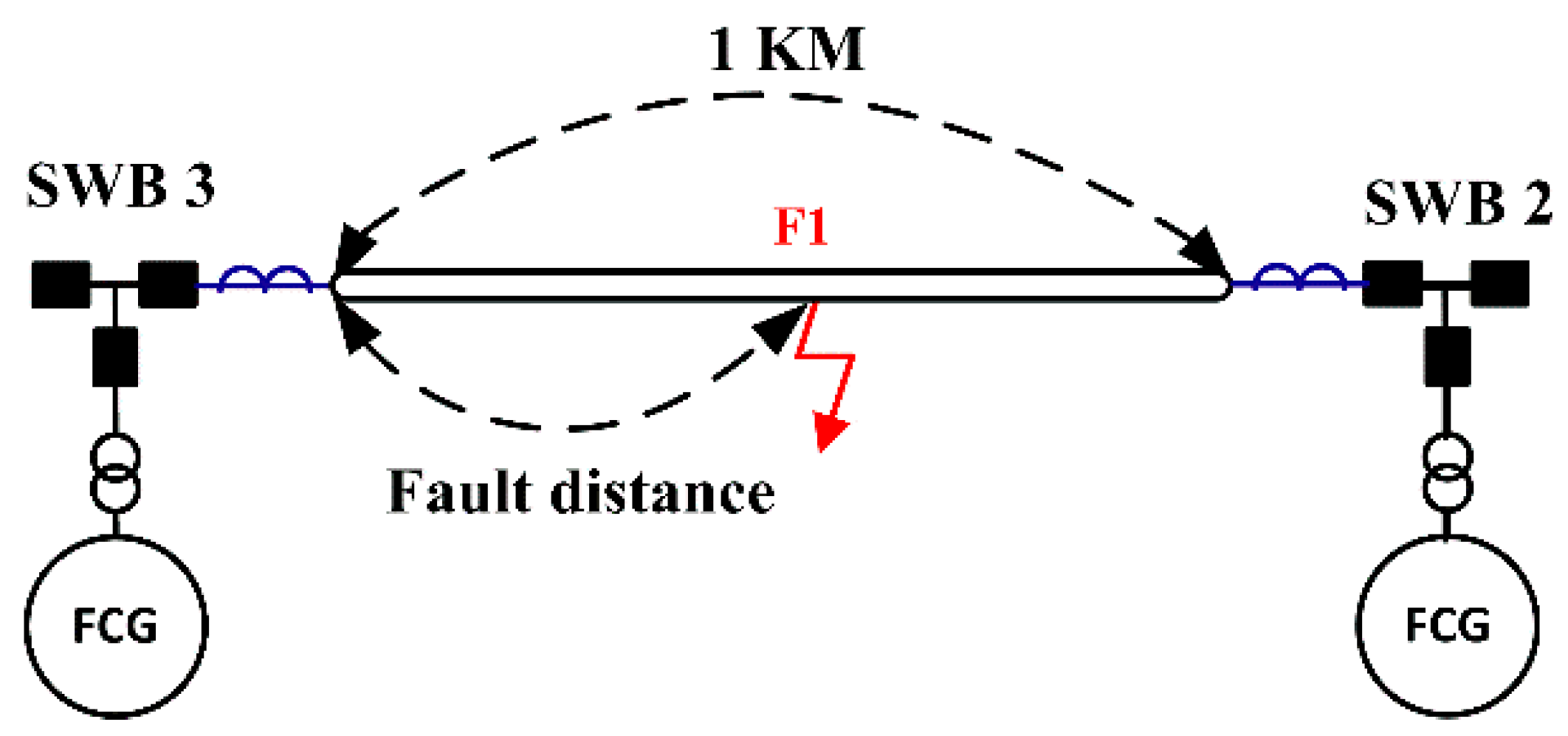
The fault location is shown in
Figure 16. The fault distance varied from 0.2 km to 0.8 km from SWB3.
Table 4 lists the simulation results for faults in different positions. In the table, Zero-Positive denotes the angle difference between the zero-sequence current and the positive-sequence current.
5. Conclusions
This paper proposes a protection method for SLG faults in ungrounded offshore wind farms incorporating FRC-WTs. The proposed method is based on the angle difference between the zero-sequence current and the positive-sequence current, using unsynchronized current phasors measured by unit protections. Each unit protection collects the unsynchronized current phasors from two adjacent nodes and synchronizes them by aligning the positive-sequence currents to the same phase angle. The faulted section is identified by comparing the phase angles of the synchronized zero-sequence currents in adjacent nodes. Once the faulted section is identified, circuit breakers are tripped to isolate the faulted section. This method could be used even if the number of wind turbines is high. The proposed method differs from conventional protection methods because time synchronization is not necessary between different unit protections, and there is, therefore, no requirement for GPS to be installed at every node. Simulations of an ungrounded offshore wind farm with relay models were carried out using PSCAD/EMTDC. The simulation results show that the proposed method can detect an SLG fault and locate the fault section. Although this paper focused on ungrounded offshore wind farms incorporating FRC-WTs, the proposed method could also be applied to ungrounded DFIG (doubly fed induction generator)-WT based offshore wind farms. In the future, protection methods for line-to-line, line-to-line-to-ground, and three-phase faults will be developed, and an offshore wind farm with FRC-WTs will be implemented in a real-time digital simulator to evaluate the entire protection method.


