Article

Investigation of Methane Oxy-Fuel Combustion in a Swirl-Stabilised Gas Turbine Model Combustor

Department of Energy Sciences, Lund University, Ole Römers väg 1, Lund SE-22100, Sweden
*
Author to whom correspondence should be addressed.
Energies 2017, 10(5), 648; https://doi.org/10.3390/en10050648
Submission received: 27 March 2017 / Revised: 27 April 2017 / Accepted: 28 April 2017 / Published: 8 May 2017
(This article belongs to the Section I: Energy Fundamentals and Conversion)

Abstract

:
CO2 has a strong impact on both operability and emission behaviours in gas turbine combustors. In the present study, an atmospheric, preheated, swirl-stabilised optical gas turbine model combustor rig was employed. The primary objectives were to analyse the influence of CO2 on the fundamental characteristics of combustion, lean blowout (LBO) limits, CO emission and flame structures. CO2 dilution effects were examined with three preheating temperatures (396.15, 431.15, and 466.15 K). The fundamental combustion characteristics were studied utilising chemical kinetic simulations. To study the influence of CO2 on the operational range of the combustor, equivalence ratio (Ф) was varied from stoichiometric conditions to the LBO limits. CO emissions were measured at the exit of the combustor using a water-cooled probe over the entire operational range. The flame structures and locations were characterised by performing CH chemiluminescence imaging. The inverse Abel transformation was used to analyse the CH distribution on the axisymmetric plane of the combustor. Chemical kinetic modelling indicated that the CO2 resulted in a lower reaction rate compared with the CH4/air flame. Fundamental combustion properties such as laminar flame speed, ignition delay time and blowout residence time were found to be affected by CO2. The experimental results revealed that CO2 dilution resulted in a narrower operational range for the equivalence ratio. It was also found that CO2 had a strong inhibiting effect on CO burnout, which led to a higher concentration of CO in the combustion exhaust. CH chemiluminescence showed that the CO2 dilution did not have a significant impact on the flame structure.

1. Introduction

Oxy-fuel combustion in gas turbine applications has attracted a great deal of attention due to its potential to reduce CO2 emission to zero, thereby offering one of the most promising strategies for climate change and sustainable development issues [1]. The main concept of oxy-fuel combustion is to burn fuel using pure oxygen rather than air as the primary oxidant. As a result, large N2 flow rates are avoided and the formation of NOx is significantly eliminated, while the combustion products mainly consist of CO2 and H2O. A simple condensation process can then be employed to remove the H2O from the flue gas, leaving the CO2 for capture and storage, thus mitigating the cost and difficulty significantly compared with CO2 separation in conventional air/fuel combustion. The CO2 separated from the flue gas can be sequestered underground or used in other applications such as enhanced oil recovery or enhanced coal bed methane recovery [2,3]. Compared with current conventional power generation systems, the main drawback of the oxy-fuel combustion cycle is the need for an air separation unit (ASU) which has both a high energy consumption and high investment costs for equipment in most cases [4]. In order to make full use of O2 while achieving the complete combustion of fuel, oxy-fuel combustion is preferably carried out under stoichiometric conditions. To reach an appropriate combustion temperature, a certain amount of recycled flue gas is used in dilution. Based on the oxy-fuel combustion concept, several power cycles have been put forward with the modification of existing gas turbine cycles, e.g., Graz cycle and Matiant cycle.
The current study focuses on the influence of CO2 dilution on the combustor operation, flame structure and emission performance within the oxy-fuel combustion process. In cases of combustion such as these, the diluting fluid primarily consists of CO2 with some impurities such as argon, nitrogen or steam. Compared to conventional air-fuel combustion, the existence of CO2 in place of N2 probably leads to changes in both the physical and chemical properties of the combustion process. Firstly, the thermodynamic properties, and particularly the specific heat capacity of the diluting fluid, are very different for large temperature variations. The molar specific heat of CO2 is about 1.28 times larger than N2 at 298.15 K and 1.7 times at 2000 K (data on gas properties can be acquired from the NIST Reference Fluid Thermodynamic and Transport Properties Database). As a result, less CO2 is required to obtain a certain combustion temperature at a given equivalence ratio than for N2-diluted combustion. In the second place, CO2 plays a more important role in both radiative absorption and emission than either N2 or O2 [5,6,7,8,9] and the flame temperature is likely to be affected. The existing numerical results suggest that the CO2 creates additional preheating for reactant mixtures through the radiative absorption of heat emitted from the recycled combustion products, consequently improving the flame velocity and extending the flammability range relative to calculations which neglect radiative effects. In addition, some investigations have indicated that the presence of a large amount of CO2 has a strong effect on the chemical kinetics of combustion, meaning that CO2 is not a passive diluent but plays a more active role in the chemical reactions than N2-diluted flames [10,11,12]. For instance, CO2 has been confirmed to compete with H radicals in some reactions, such as the enhanced reverse reactions of CO + OH ↔ CO2 + H and enhanced recombination reactions such as H + O2 + M ↔ HO2 + M [13], due to the higher third body efficiency of CO2 (2.4 times higher than N2 in the mechanism described by Davis et al. [14]). As a result, the laminar flame speed is considerably reduced (in comparison to CH4/air combustion), particularly at low pressures [15].
Since there are differences in dilution properties, various combustion characteristics have been investigated for CO2-diluted combustion, both experimentally and theoretically. The combustion instabilities were studied experimentally in [16] and the results revealed that the flame dynamics were highly affected by the concentration of O2 in the O2/CO2 mixtures. The flammability limits were investigated theoretically in [17,18,19], and several theoretical and empirical models were developed to predict the limits of flammability. Some gas turbine-related research was presented in [20,21,22,23] in which the authors concluded that the stability of the oxy-combustion was affected when the oxygen concentration in the oxidiser mixture was below certain critical values compared to fuel-air combustion. In addition, ignition was not possible when the oxygen concentration was less than 21% in the oxidiser mixture. Despite a great deal of prior work, the effects of CO2 on the fundamental characteristics of combustion, combustor operation and CO emission issues of premixed methane combustion have not been fully characterised for operating conditions relevant to gas turbines. The present work aims to evaluate the main diluting species (CO2) using an optical and swirl-stabilised gas turbine combustor model under atmospheric pressure. A CH4/O2/CO2 reactant mixture was used in which the O2 concentration was 30% in the oxidiser (hereinafter referred to as an OF30 flame). CH4/air flames were studied as reference cases. The effects of CO2 dilution on the premixed, swirl-stabilised methane flame were studied for three preheating temperatures. To assist in gaining an understanding of the experimental results and to study the important characteristics of combustion, chemical kinetic simulations were performed. The lean blowout (LBO) limits and CO emissions were measured and compared with the reference methane air flames. CH chemiluminescence imaging was performed in order to characterise the flame shape and locations [24]. In order to gain a better understanding of the flame structure, the inverse Abel transformation was used to analyse the CH chemiluminescence distribution. More details of the experiment design and laboratory equipment are given in the following section.

2. Experimental Apparatus and Methods

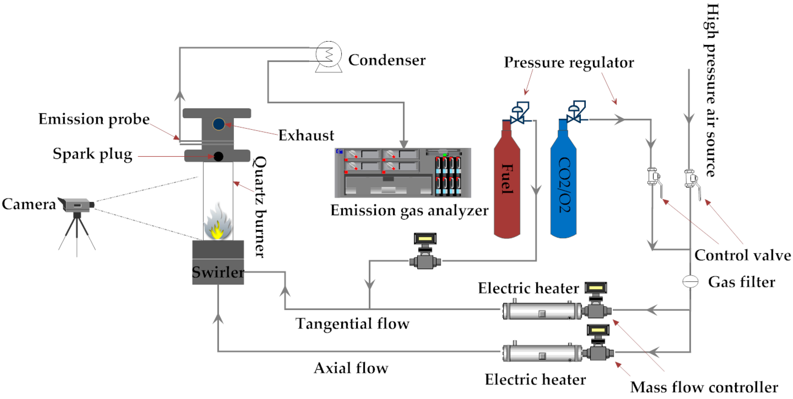
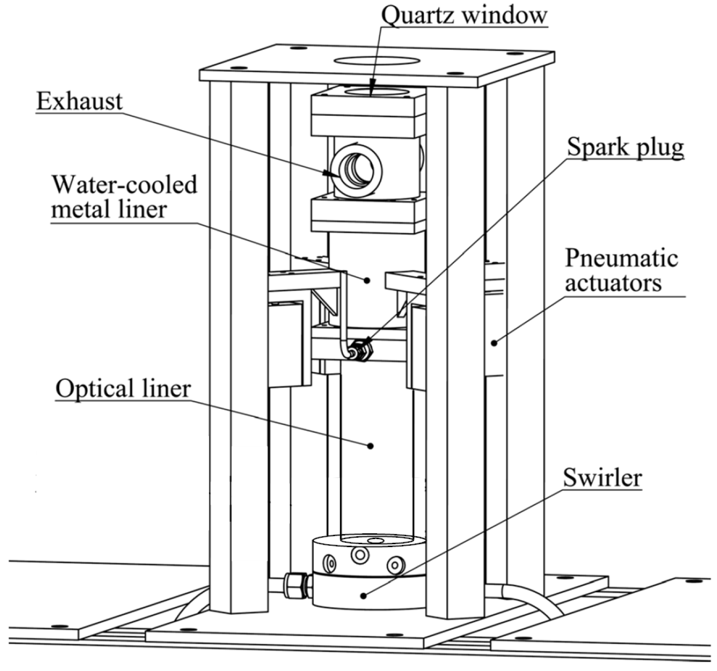
2.1. Flow Paths and Combustor

The configuration of the experimental equipment and the flow paths designed for the present study are shown in Figure 1. The combustor is supplied by two oxidiser streams and one fuel source. The air fed into the combustor for the flame is supplied from a pressurised laboratory air source, while the CO2/O2 gas mixtures are supplied from pressurised gas bottles. The two types of oxidants (air and CO2/O2) are controlled by two valves which can be used to select the source of the desired oxidant depending on the experimental requirements. Both of the axial and tangential oxidant streams are metered and controlled using differential pressure mass-flow controllers (MCR250, Alicat Scientific, Tucson, AZ, USA). In order to obtain the desired combustor inlet temperature, the two oxidant streams can also be preheated individually using two feedback-controlled air heaters (Sureheat Jet, Sylvania, Exeter, NH, USA) of 8 kW power. A K-type thermocouple with a diameter of 1.5 mm and accuracy of 2.2 K is employed in the measurements to detect the combustor inlet temperature. Methane (CH4) fuel of 99.98% purity is used in the experiment and supplied from pressurised gas bottles. The fuel stream is metered and controlled using a differential pressure mass-flow. After this, the fuel is injected at the tangential flow. All reactants were mixed in the swirler, which is followed by a 60 mm long mixing tube, and then supplied to the combustor. A force-ventilated extractor hood was used during the experiments to discharge the exhaust gases generated from the combustor.
The combustor, with an overall length of 350 mm, is mounted on a pneumatic actuator system as shown in Figure 2. The inner surface of the combustor has a cylindrical shape. The liner consists of two sections: the upper section is made of metal, while the lower one is made of quartz, which provides optical access to the flame. A swirler is mounted upstream of the entrance of the combustor. The experimental setup contains two oxidant streams and one fuel stream. One oxidant stream enters the swirler from the axial direction, and the other from a tangential direction. In the swirler, the two oxidant streams can be combined with adjustable proportions and then supplied to the combustor. Before entering the swirler, the axial oxidant flow passes through a sintered flow straightener. This consists of two pieces of sintered stainless steel disc, which have an average porosity of 200 µm. The oxidant flow entering the swirler in the tangential direction passes through four channels of dimensions 3 mm wide by 10 mm high. A more straightforward perspective is given in Figure 3, which shows a cross-sectional sketch of the combustor.

2.2. Measurement Conditions

The LBO limits, CO emission and CH chemiluminescence of the flames were investigated according to the operating conditions, and these are presented in Table 1. To study the effect of CO2 dilution on the flames, the experiments were divided into two groups: the OF30 and CH4/air reference flames. The CH4/air reference flames were operated at 72.9 SLPM (standard litre per minute) air flow. The OF30 flames were operated under two CO2/O2 mass flow conditions: 50.9 SLPM (the same O2 mass flow as the CH4/air flame) and 72.9 SLPM (the same total oxidiser mixture mass flow as the CH4/air reference flames). For brevity, the OF30 flame with 50.9 SLPM CO2/O2 is hereinafter referred to as the OF30-1 flame and the OF30 flame with 72.9 SLPM CO2/O2 as the OF30-2 flame.

2.3. Lean Blowout Measurement

Combustion lean blowout is one of the most critical operability issues for a combustor. Blowout refers to situations in which the flames become detached from the anchored location and are physically “blown out” from the combustor. As discussed in the literature [25], flames diluted with large amounts of CO2 have slower chemical kinetics than methane–air flames. Compared with flashback, blowout is more likely to be a problem in oxy-combustion systems. In the present study, the LBO limits for certain flow cases were determined by gradually turning down the fuel flow (i.e., reducing Ф) until the flame physically disappeared from the combustor. The equivalence ratio at which the flame disappeared was defined as the lean blowout limit. In the initial stages, the decrease in fuel flow could be carried out in large steps until the flame became unstable. Following this, the reduction in fuel flow was achieved using 0.1 SLPM steps, i.e., the smallest possible steps of the mass flow controller.

2.4. Emission Measurement

The emission system consisted of a Rosemount Oxynos 100 paramagnetic O2 gas analyser, a Rosemount Binos 100 NDIR (non-dispersive infrared photometer) CO/CO2 gas analyser and a CLD 700 chemiluminescence NO/NOx Analyser. For the present study, only O2, CO, and CO2 are of interest. The measurement ranges for O2, CO and CO2 were 0–25%, 0–1000 ppm and 0–16% respectively. The linearity and resolution of the emission measurement is smaller than 1%. A water-cooled combustion exhaust gas sampling probe was mounted near the combustor exit. The emission probe was designed with multiple holes, which can ensure an average sampling of CO, CO2, and O2 exhausts. To avoid condensing in the gas analyser, the sample gas collected was directed into a cooler, where a simple condensation process was utilised to remove water vapour from the sample gas. The dry emission sample was then analysed for the previously mentioned gas samples. In order to minimise measurement errors, the emission gas analysers were calibrated prior to each experiment using standard calibration gases.
During the experiments, various equivalence ratios (Ф) were achieved by adjusting the settings on both fuel and oxidiser mass-flow controllers. Thus, validation of the device performance states of Alicat mass flow controllers is essential. A double check utilising combustion exhaust products (O2, CO2, and CO) was performed as a validation method [26]. Good agreement was found between the ФEMI based on emissions and the ΦMFC based on the fuel/air ratio. An NDIR gas analyser was used in the CO/CO2 emission measurement as described above. Due to limitations on the instruments, the interference of CO2 and H2O on the measured CO and the interference of O2 on the measured CO2 needed to be considered in the simultaneous emission measurement [26]. A cross-compensation algorithm was derived using tests on the gas analyser and was used to compensate for this interference.

2.5. Flame Visualisation with CH Chemiluminescence Imaging

Time-averaged CH chemiluminescence images were recorded for both the CH4/air and OF30 flames. A CCD camera (D70s, Nikon, Tokyo, Japan) equipped with an AF Nikkor lens (50 mm/F1.8D, Nikon, Tokyo, Japan) and a band-pass CH filter (430/10, LaVision, Göttingen, Germany) was used to take these images. CH chemiluminescence images were recorded with a resolution of 3008 × 2000 pixels and an exposure time of 0.77 s. The aperture was set as f/1.8 for all the images. Since a cylindrical combustor was used in these experiments, the swirl-stabilised flame can be assumed to be axially symmetric. Typically, CH chemiluminescence images are considered to be an integrated line-of-sight measurement. In order to acquire CH intensity distribution according to the projection images, the inverse Abel transform was performed to reconstruct the CH images. Figure 4 presents a comparison of CH chemiluminescence images both before and after performing the inverse Abel transform.

2.6. Chemical Kinetic Simulation

An analysis based on the simulation of chemical kinetics is very important due to its ability to provide detailed chemical kinetics. The effects of CO2 dilution on the adiabatic flame temperature, laminar flame speed, ignition delay time and blowout residence time were studied and discussed under atmospheric pressure utilising chemical kinetics simulations which can provide comprehensive information on the combustion process. In the current work, the simulation was carried out using the Chemkin-Pro software package [27] and the GRI-Mech 3.0 chemical kinetic mechanism [28], a compilation of 325 elementary chemical reactions, associated rate coefficient expressions and thermochemical parameters for the 53 species.

3. Results and Discussion

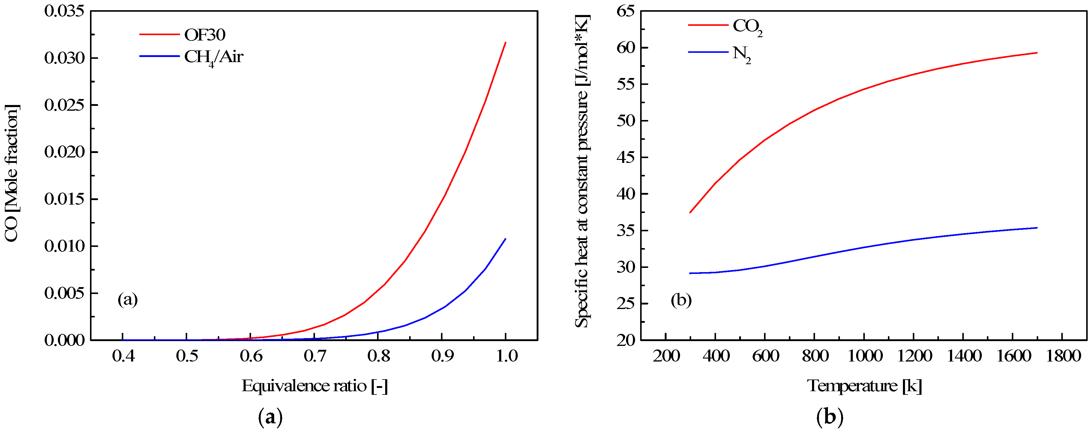
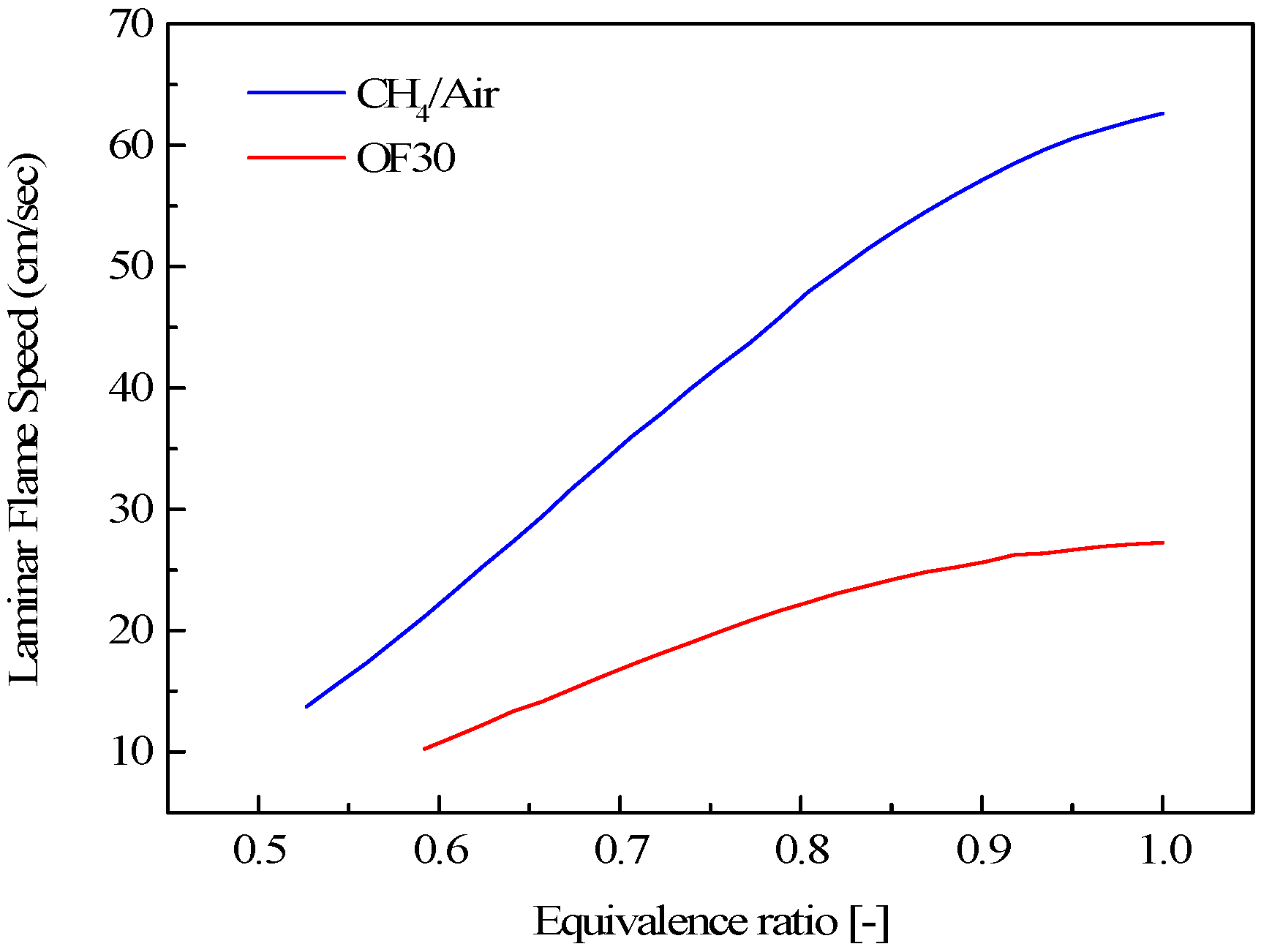
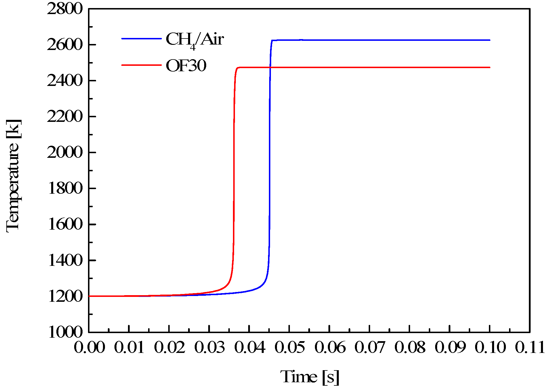
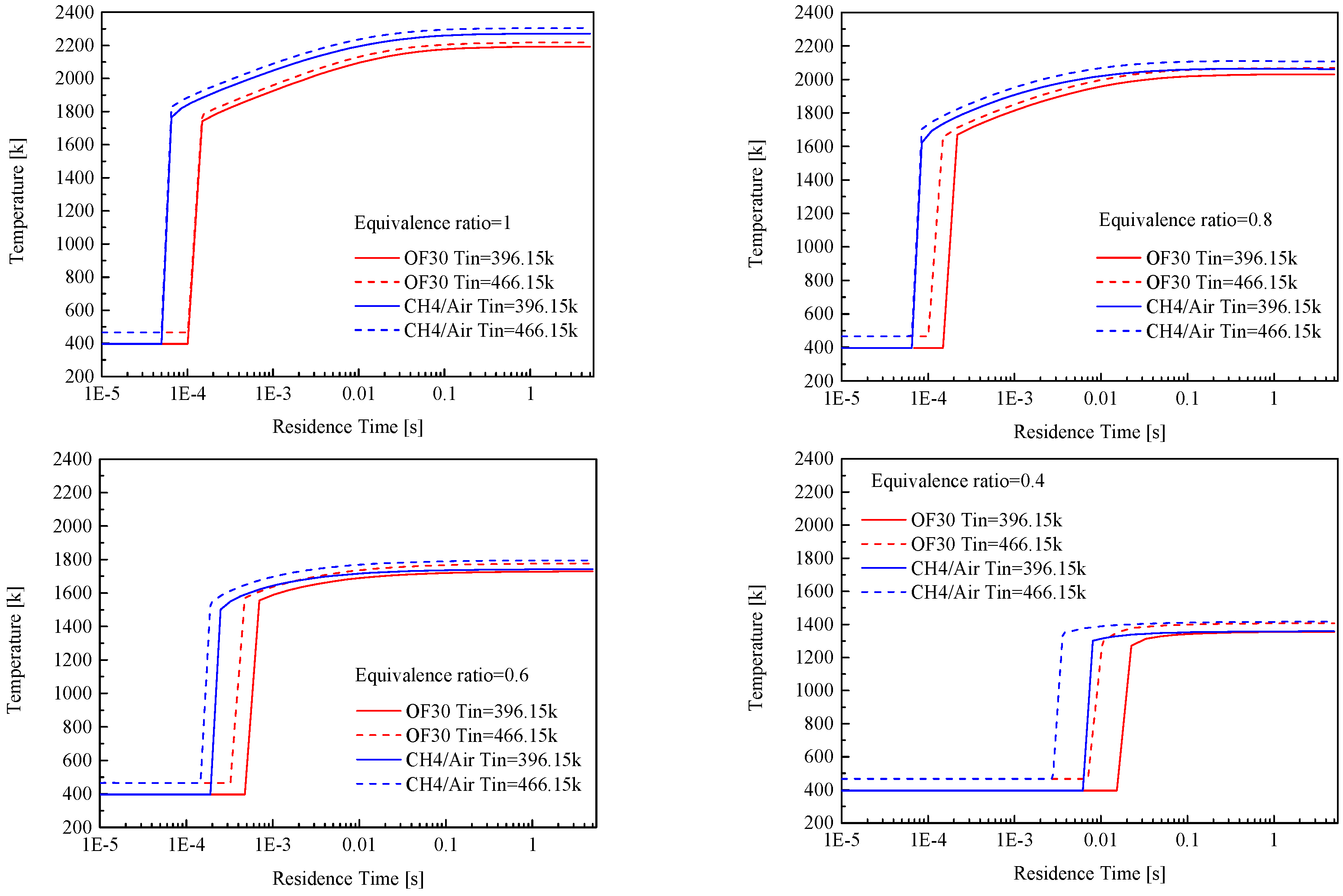
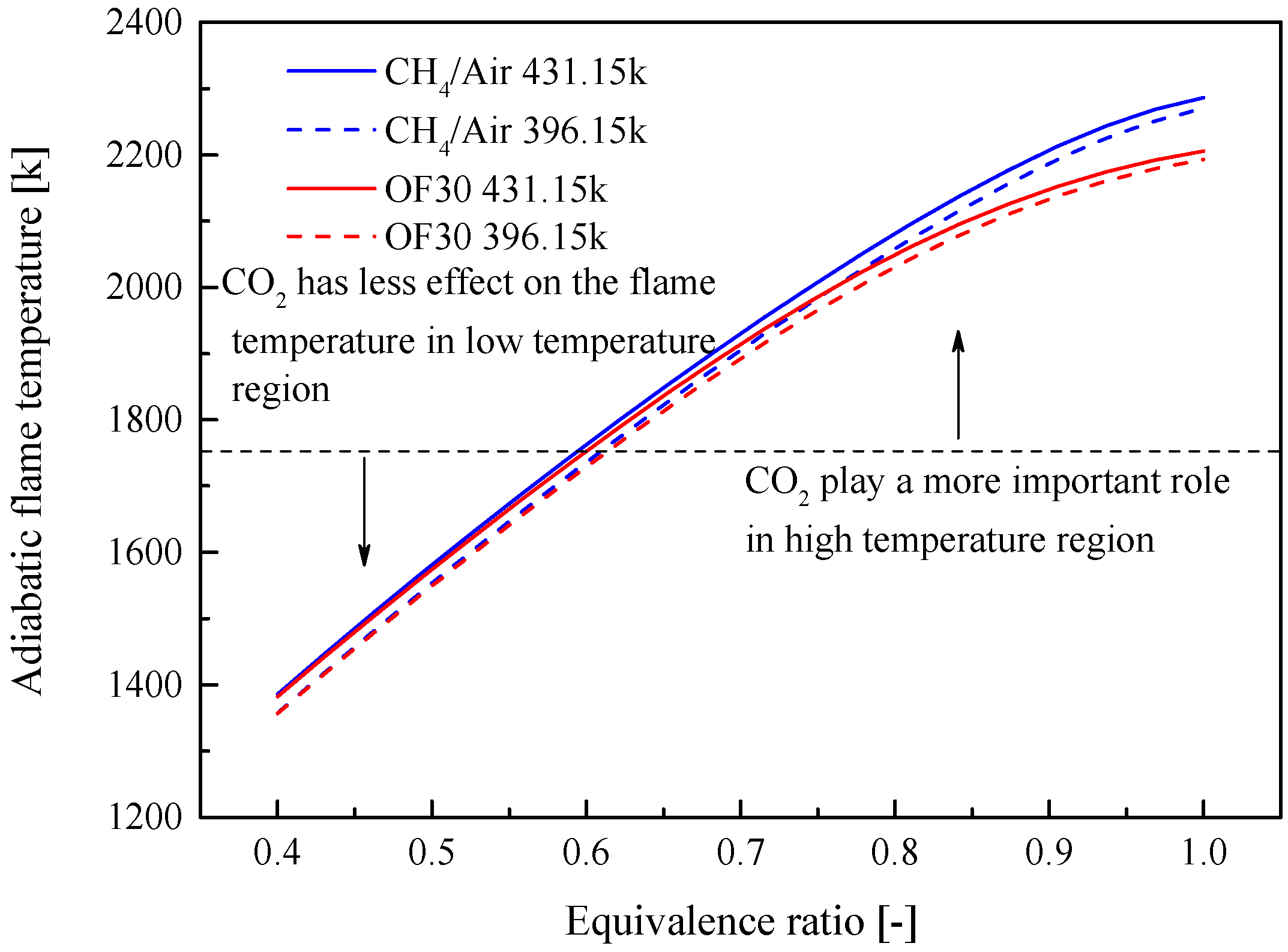
3.1. Effect of CO2 on Some Fundamental Combustion Characteristics

Figure 5 shows a comparison of the adiabatic flame temperature of the CH4/air flame and the OF30 flame, with combustor inlet temperatures of 396.15 and 431.15 K. For the two preheating temperatures, within the region of low equivalence ratio, the difference in adiabatic flame temperature between the CH4/air and OF30 flames is almost negligible. However, within a region of high equivalence ratio, the difference in adiabatic flame temperature becomes increasingly significant.
There may be two reasons contributing to this difference in adiabatic flame temperature. On the one hand, in a region of equivalence ratio of above approximately 0.6, the CO mole fraction of the OF30 flame is larger than the CH4/air flame (Figure 6a). This indicates that the combustion efficiency of the OF30 flame in the high equivalence ratio region is lower than that of the CH4/air flame. As a result, the OF30 adiabatic flame temperature curve drops far below that of the CH4/air temperature profile. The higher CO concentration of the OF30 flame has been explained in work by Park et al. and Glarborg et al. [29,30]. These authors’ results indicated that the presence of CO2 leads to a negative effect on CO burnout by competing for H radicals in the following reaction:
CO 2 + H CO + OH
On the other hand, as N2 and CO2 are the two main dilution species in CH4/air and OF30 flames, their thermodynamic properties may also have an influence on the adiabatic flame temperature. Figure 6b shows the variation in Cp (specific heat at constant pressure) with temperature at atmospheric pressure. It can be seen that the Cp of CO2 is much higher than that of N2 over the entire temperature range from 400 to 1750 K. Hence, the difference in Cp can be expected and is another reason for a lower flame temperature for OF30 as compared with CH4/air flame. In addition to the above two reasons, the dissociation of CO2 at high temperatures may also contribute to a decrease in the OF30 flame temperature.
The influence of CO2 on laminar flame speed is illustrated in Figure 7. To ensure a stabilised premixed flame, a basic concept is to keep a balance between the flame speed and flow velocity of the reactant mixtures. When the flame speed is less than the flow velocity, the flame will be physically blown out of the combustor. Although in turbulent combustion the flow velocity field is very complex, and this concept is not straightforward, this has a significant effect on the interpretation and prediction of lean blowout events. Figure 7 shows that the laminar flame speeds are strongly influenced by CO2 within the operational range of equivalence ratio. Along with the increase in equivalence ratio, the difference in velocity of OF30 and CH4/air flames becomes increasingly pronounced. The maximum laminar velocity of the CH4/air flame is more than twice as large as the OF30 flame. The reason for this difference in velocity could be the negative effect of CO2 on the chemical reaction rate, which is strongly influenced by the flame temperature and reactant concentrations.
In the practical application of gas turbines, one difficult question is how to avoid auto-ignition, in order to protect burner components and to control pollutant emissions. An understanding of ignition delay time can be very helpful in solving auto-ignition problems in turbine industries. In combustion applications, various definitions of the ignition time are available, both experimentally and computationally. For example, this can be defined as the time at which either the maximum or onset of certain species concentrations is reached, the time at which a specified rate of temperature increase occurs, or the time at which luminous radiant output from the system is first observed [31]. The reported experimental data can vary greatly, depending on which definition is used in the experiments. In the present computations, the start point of ignition was selected as the time at which the maximum temperature increasing rate is reached.
Figure 8 presents numerical predictions of the ignition delay time under conditions of an equivalence ratio of 1 and a temperature of 1200 K. A closed, isobaric and homogeneous reactor was utilised to calculate the ignition delay time. Based on Figure 8, at atmospheric pressure and 1200 K, the OF30 flame has a shorter ignition delay time and a lower adiabatic flame temperature. It is generally accepted that the ignition process is primarily controlled by chemical kinetics. The shorter ignition delay time for OF30 flame may be caused by a higher O2 concentration in the oxidiser, which probably accelerates the chain branching reactions and results in a faster ignition progress.
The blowout residence time for different combustion dilution components is also a relevant parameter for stable operation. The blowout residence time can be considered as the minimum time needed for chemical reactions. In the present work, the combustor was modelled as a PSR (perfectly stirred reactor) in which the mixing process is infinitely fast, and the combustion is only controlled by the chemical reaction rates. In Figure 9, the blowout residence times for the OF30 and CH4/air flames are presented for four equivalence ratios (1, 0.8, 0.6, and 0.4) and two different preheating temperatures. When the residence time is decreased, the flame temperature is not initially influenced, as there is still enough time to complete the reactions. In the following stages, the temperature slowly begins to fall. The temperature then suddenly drops to the initial unburned temperature. In the current work, we define the blowout residence time as the “critical residence time” (as shown in Figure 9) after which the temperature drops back to the initial preheating value.
The blowout residence time is summarised and plotted in Figure 10. It can be seen that the CH4/air and OF30 flame needs a larger blowout residence time when the equivalence ratio is decreased. With the same equivalence ratio and preheating temperature, the OF30 flames require a larger blowout residence time than the CH4/air flames, meaning that the OF30 flame is more likely to be blown out due to the lower chemical reaction rate. In the CH4/air flame at the above equivalence ratio of 0.8, the effect of preheating temperature on blowout residence time is negligible. However, when the equivalence ratio is decreased further, the difference becomes increasingly significant. For the OF30 flame, the effect of preheating temperature is significant at a higher equivalence ratio than for the CH4/air flame.

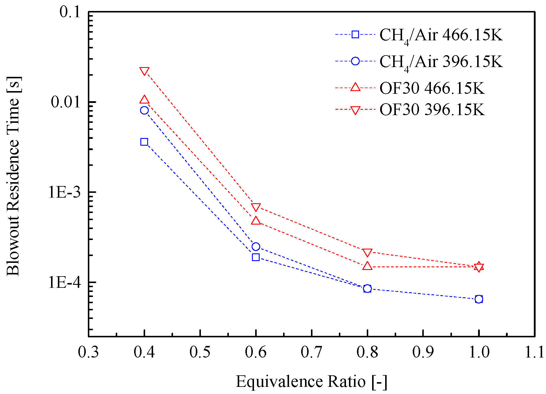
3.2. Lean Blowout Limits
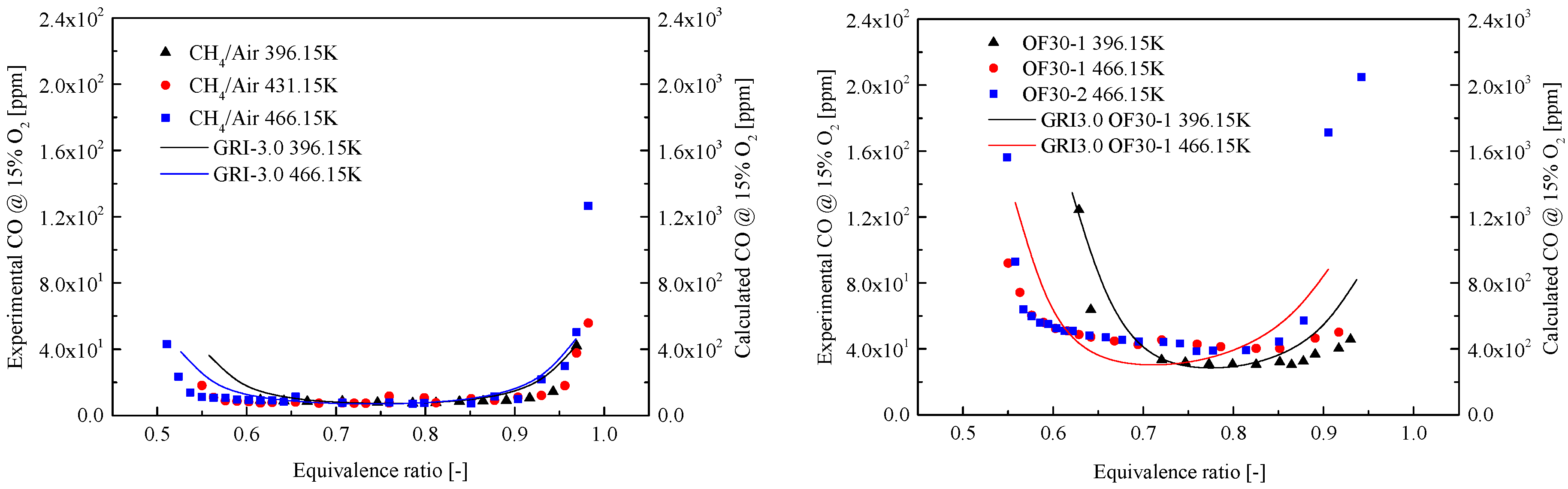
As discussed in the previous section, a basic requirement for a stabilised flame is that the flame speed must match the flow velocity. Another basic requirement is that the flow residence time must be long enough compared to the chemical time. To evaluate these two characteristic time scales, a dimensionless number, Da, is used and this is defined as
Da = τ r e s / τ c h e m
This number was adopted for the evaluation of the lean blowout behaviour in the current work. It is well-known that the CO2 dilution plays a very important role in combustion stability through its effects on the chemical reactions. This chemical kinetic effect of CO2 can be quantified using the chemical time τchem, defined as
τ C h e m = δ L / S L
where δ L is the flame thickness (the reaction zone thickness) and S L is the laminar flame speed. A further illustration of the flame thickness is presented in Figure 11. In this diagram, a laminar flame propagates from right to left. T is plotted as a function of distance. Tflame is the flame temperature and Tin is the unburned reactant mixture temperature. δ L can be calculated a
δ L = Δ T f l a m e ( d T d x ) _ m a x
A comparison of the flame thickness at LBO limits is shown in Table 2.
The chemical time is a very important time scale for measuring the kinetic reaction rate for the flame extinction behaviour [32,33,34,35]. Based on this equation, τ c h e m can be interpreted as the time needed for the flame to propagate across the reaction zone. From another point of view, this could also be expressed as the minimum residence time needed to complete the chemical reactions. The residence time τ r e s in Da is defined as
τ r e s = L r e f / V r e f
where L r e f is the recirculation zone reference length of the combustor and V r e f is the reference velocity of the flow. In the present study, the mixing tube exit diameter was used as the reference length [36].
Figure 12 presents the LBO limits as a function of Da number and preheating temperature. As expected, the LBO limits of OF30-1 are higher than the CH4/air flame. One reason could be the low chemical reaction rate of CO2 which is supported by the chemical kinetic simulation results presented in Figure 5, Figure 7 and Figure 10. Another reason could be the stronger radiation ability of CO2. The higher preheating temperatures extend the lean blowout limits to lower equivalence ratios. Compared with the CH4/air flame, the OF30-1 flame always has a lower Da number for the lean blowout points at the same preheating temperature, due to the longer chemical reaction time. The lean blowout limit of OF30-2 is very slightly improved by the increase in mass flow rate compared with OF30-1; however, the Da number for OF30-2 at the lean blowout point shifts to a smaller value.
A further analysis of the flammability limits is shown in Figure 13. To satisfy the first flammability limit, a sufficiently high temperature is needed to provide enough radicals and energy to the reaction zone. When the equivalence ratio decreases to ΦLBO, the flame temperature is too low and the reaction zone cannot ignite the surrounding reactants, and flame lean blowout will then take place. To meet the second flammability limit, the flame can only survive in the combustor when the Da number is greater than DaLBO. In other words, compared with the chemical time τ c h e m , the residence time τ r e s must be long enough to complete the reactions. In summary, the flame with a higher preheating temperature and a smaller DaLBO number has a broader range of flammability.

3.3. CO Emission

Figure 14 shows CO emissions as a function of equivalence ratios for the CH4/air and OF30 flames. The OF30 flame has a higher CO concentration level than the CH4/air flame, indicating the inhibiting effect of CO2 on the CO burnout. For all the combustion cases, the CO emission shows a steep increase when the flame is operated close to stoichiometric conditions or the lean blowout limits. In the region between these two steep increases, the CO concentration remains low and stable. Under conditions in which the flame is operated close to the LBO limits, the chemical reaction rate is too low to complete the combustion. It can be therefore concluded that incomplete combustion is the main reason for the high concentration of CO in the exhaust. At the moment when the flame is operated close to stoichiometric conditions, a high flame temperature can be expected. This high flame temperature has a strong negative effect on the CO oxidation reaction, which is the main heat release reaction in methane combustion. According to the thermal dynamic properties of CO2, the high flame temperature may also intensify CO2 dissociation, which also contributes to the CO increase. In addition, under conditions where the equivalence ratio approaches 1, there is almost no extra oxygen, which is essential for fast and complete CO oxidisation with limited residence time. Consequently, the combined effects of the reasons discussed above give rise to the CO trend shown in Figure 14. Chemical simulations were conducted to predict the CO emissions with a single reactor. The solid lines represent the simulation results which indicate that there is no quantitative agreement between the experimental data and the modelled CO emissions. For the CH4/air flame, the simulation results capture the trend very well. However, for the OF30 flame, the simulated trend does not match the experimental data as well as for the CH4/air flame. The attempt to create a time- and resource-saving model failed; this is probably because the simplified heat loss estimation and the assumption of the PSR do not correspond to the real situation. A more complicated chemical reactor network may be required to model the CO quantitatively.

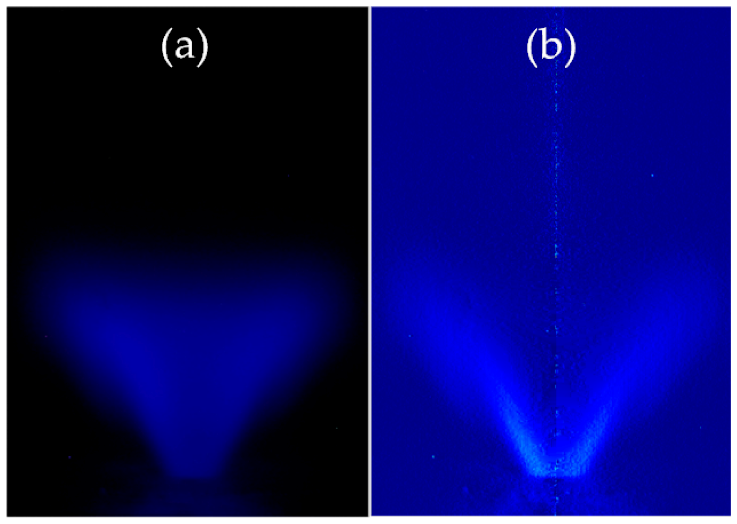
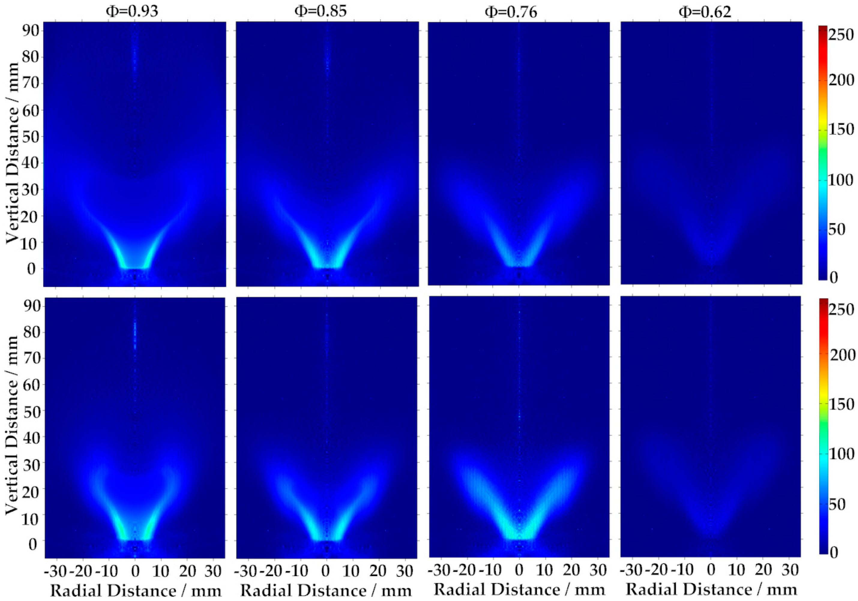
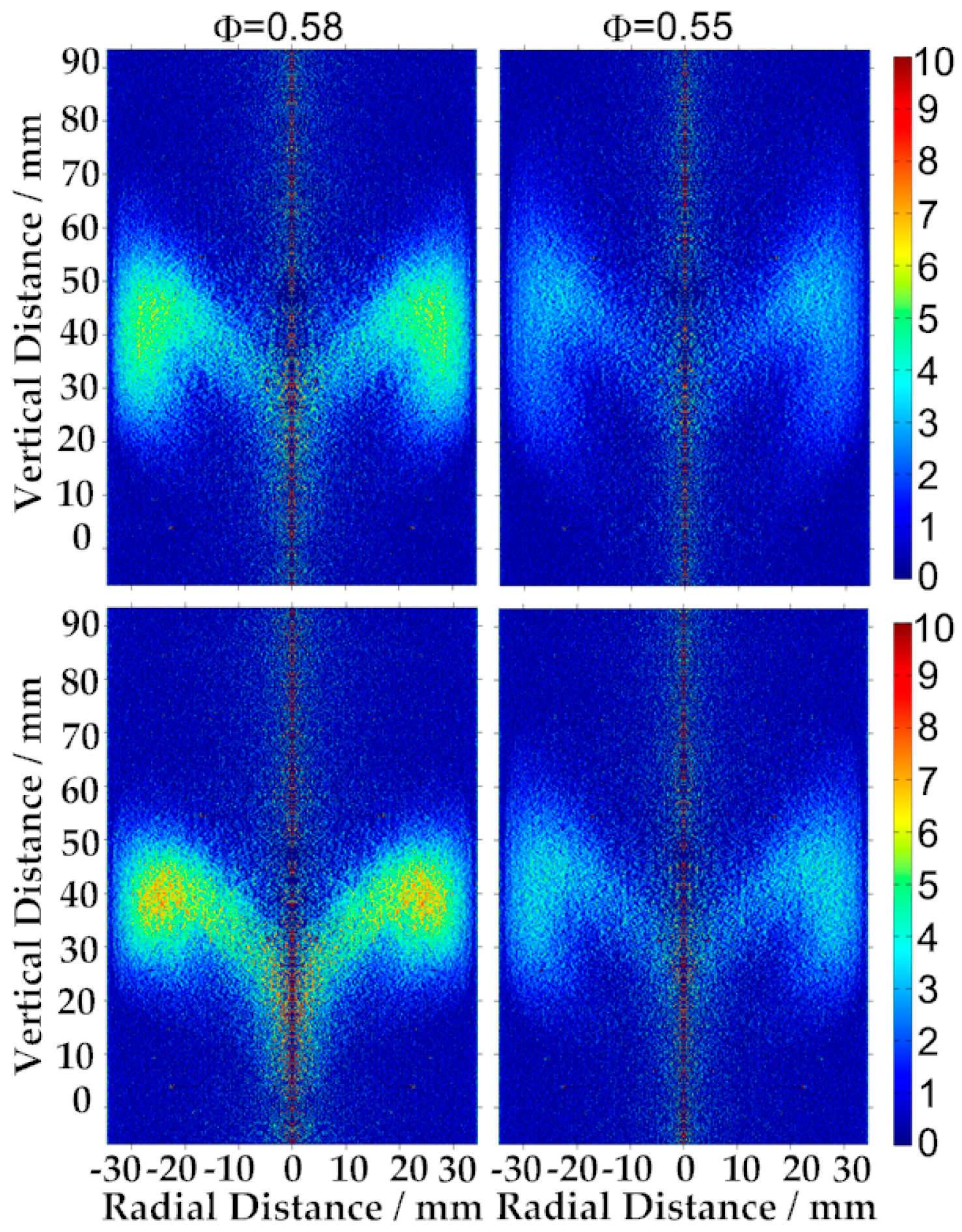
3.4. Flame Observation

Figure 15 presents the evolution process of the CH chemiluminescence distribution on an axisymmetric cross-section with varying equivalence ratio. The OF30-1 and CH4/air flames are compared here. For the OF30-1 flame, at a range of equivalence ratios of 0.93 to 0.62, the flame is anchored at the edge of the combustor inlet. Unfortunately, no simultaneous velocity profile is available. However, it can be estimated that the flame front is located at the shear layer of the inner recirculation zone. Reducing the equivalence ratio increases the thickness of the reaction zone and extends the bottom reaction zone towards the combustor centre line. With a decrease in equivalence ratio, the averaged CH concentration in the inner recirculation zone gradually decreases, while the downstream reaction zone extends to the wall. The CH4/air flame basically follows the same pattern within the range of variation of the equivalence ratio. It can be observed that the thickness of the reaction zone is enhanced (when Φ ≥ 0.76) compared with the OF30-1 flame.
Under conditions where the equivalence ratio is below 0.62, the CH intensity is too low to observe. The intensity scale must therefore be adjusted to obtain the desired visible image. The main reaction zone is observed to rise from the previously anchored place and attach to the combustor wall (Figure 16) when the equivalence ratio (for both OF30-1 and CH4/air flames) was reduced too close to the lean blowout limit. A further decrease in equivalence ratio leads to the LBO. The variation in the stabilised location of the reaction zone can be understood as a balancing process between the residence time τ r e s and the chemical reaction time τ c h e m . When the flame temperature is decreased (as a result of reducing the equivalence ratio), the chemical reaction rates are not fast enough to keep the reaction zone in the anchored place. The reaction zone therefore has to move downstream (the residence time for the reactions is increased) in order to adapt to the longer chemical reaction time.

4. Conclusions

The effect of CO2 dilution on premixed methane combustion in a swirl-stabilised gas turbine model combustor was investigated at atmospheric pressure. The results of chemical simulation and experimental investigation of the CH4/O2/CO2 flame and the reference CH4/air flame were studied and compared. The Chemkin-Pro software package and GRI-Mech 3.0 chemical kinetic mechanism were used in these chemical simulations. The LBO limits, CO emission capability, and flame structure and location were explored. According to the simulation results, the adiabatic flame temperature is influenced by CO2 above a certain critical value (approximately 0.6). However, this influence can be neglected under conditions where it is close to LBO limits. The OF30 flame has a smaller laminar flame speed compared with the CH4/air flame, and the difference in laminar flame speed becomes increasingly significant with an increase in equivalence ratio. The OF30 flame is found to have a larger blowout residence time but a faster response in the ignition process, which means a smaller ignition delay time (under the initial conditions where Φ = 1 and the temperature is 1200 K). The Da number and equivalence ratio were used to evaluate the flammability limits. Two necessary flammability limits, ΦLBO and DaLBO, need to be met to allow a flame to survive in the combustor. The OF30 flame always has a higher ΦLBO limit than the corresponding CH4/air reference flame. The high preheating temperature can extend both ΦLBO and DaLBO to a smaller level. A strong inhibiting effect of CO2 on CO burnout was identified in the emission measurement, which leads to a higher concentration of CO in the combustion exhaust. The CO emission was found to show a rapid increase when the combustion was operated close to the LBO limits or under stoichiometric conditions. Time-averaged CH chemiluminescence imaging, with the inverse Abel transform, was used to characterise the flame structure and location. The results indicate that the CO2 (at a concentration of 70% in a CO2/O2 mixture) did not change the flame structure or the stabilised location compared with the CH4/air flame. Two stabilised flame regimes were formed when the equivalence ratio varied towards the lean blowout limits.

Acknowledgments

The authors gratefully acknowledge the financial support from the China Scholarship Council (CSC).

Author Contributions

Mao Li designed the experiments, performed the experimental work and wrote the paper; Mao Li and Yiheng Tong analysed the data; Marcus Thern and Jens Klingmann proofread the paper and provided the laboratory equipment.

Conflicts of Interest

The authors declare no conflict of interest.

References and Note

  1. Anderson, R.E.; Mac Adam, S.; Viteri, F.; Davies, D.O.; Downs, J.P.; Paliszewski, A. Adapting gas turbines to zero emission oxy-fuel power plants. In Proceedings of the ASME Turbo Expo 2008: Power for Land, Sea, and Air, Berlin, Germany, 9–13 June 2008; pp. 781–791. [Google Scholar]
  2. Heddle, G.; Herzog, H.; Klett, M. The Economics of CO2 Storage; Massachusetts Institute of Technology, Laboratory for Energy and the Environment: Cambridge, MA, USA, 2003. [Google Scholar]
  3. Hustad, C.-W. The Norwegian CO2-infrastructure initiative: A feasibility study. In Proceedings of the 5th International Conference on Greenhouse Gas Control Technology, Cairns, Australia, 13–16 August 2000. [Google Scholar]
  4. Stanger, R.; Wall, T.; Spoerl, R.; Paneru, M.; Grathwohl, S.; Weidmann, M.; Scheffknecht, G.; McDonald, D.; Myöhänen, K.; Ritvanen, J.; et al. Oxyfuel combustion for CO2 capture in power plants. Int. J. Greenh. Gas Control 2015, 40, 55–125. [Google Scholar] [CrossRef]
  5. Maruta, K.; Abe, K.; Hasegawa, S.; Maruyama, S.; Sato, J. Extinction characteristics of CH4/CO2 versus O2/CO2 counterflow non-premixed flames at elevated pressures up to 0.7 MPa. Proc. Combust. Inst. 2007, 31, 1223–1230. [Google Scholar] [CrossRef]
  6. Chen, Z.; Qin, X.; Xu, B.; Ju, Y.; Liu, F. Studies of radiation absorption on flame speed and flammability limit of CO2 diluted methane flames at elevated pressures. Proc. Combust. Inst. 2007, 31, 2693–2700. [Google Scholar] [CrossRef]
  7. Ruan, J.; Kobayashi, H.; Niioka, T.; Ju, Y. Combined effects of nongray radiation and pressure on premixed CH4/O2/CO2 flames. Combust. Flame 2001, 124, 225–230. [Google Scholar] [CrossRef]
  8. Guo, H.; Jub, Y.; Maruta, K.; Niioka, T.; Liu, F. Numerical investigation of CH4/CO2/air and CH4/CO2/O2 counterflow premixed flames with radiation reabsorption. Combust. Sci. Technol. 1998, 135, 49–64. [Google Scholar] [CrossRef]
  9. Ju, Y.; Masuya, G.; Ronney, P.D. Effects of radiative emission and absorption on the propagation and extinction of premixed gas flames. Symp. (Int.) Combust. 1998, 27, 2619–2626. [Google Scholar] [CrossRef]
  10. Yossefi, D.; Belmont, M.; Maskell, S.; Ben-Dor, G. Stimulation and implementation of laminar flow reactors for the study of combustion systems of ethane, methane and deborane. Fuel 1998, 77, 173–181. [Google Scholar] [CrossRef]
  11. Yossefi, D.; Ashcroft, S.; Hacohen, J.; Belmont, M.; Thorpe, I. Combustion of methane and ethane with CO2 replacing N2 as a diluent. Modelling of combined effects of detailed chemical kinetics and thermal properties on the early stages of combustion. Fuel 1995, 74, 1061–1071. [Google Scholar] [CrossRef]
  12. Natarajan, J.; Lieuwen, T.; Seitzman, J. Laminar flame speeds of H2/CO mixtures: Effect of CO2 dilution, preheat temperature, and pressure. Combust. Flame 2007, 151, 104–119. [Google Scholar] [CrossRef]
  13. Walton, S.; He, X.; Zigler, B.; Wooldridge, M. An experimental investigation of the ignition properties of hydrogen and carbon monoxide mixtures for syngas turbine applications. Proc. Combust. Inst. 2007, 31, 3147–3154. [Google Scholar] [CrossRef]
  14. Davis, S.G.; Joshi, A.V.; Wang, H.; Egolfopoulos, F. An optimized kinetic model of H2/CO combustion. Proc. Combust. Inst. 2005, 30, 1283–1292. [Google Scholar] [CrossRef]
  15. Hu, X.; Yu, Q.; Liu, J.; Sun, N. Investigation of laminar flame speeds of CH4/O2/CO2 mixtures at ordinary pressure and kinetic simulation. Energy 2014, 70, 626–634. [Google Scholar] [CrossRef]
  16. Ditaranto, M.; Hals, J. Combustion instabilities in sudden expansion oxy-fuel flames. Combust. Flame 2006, 146, 493–512. [Google Scholar] [CrossRef]
  17. Hu, X.; Yu, Q.; Sun, N.; Qin, Q. Experimental study of flammability limits of oxy-methane mixture and calculation based on thermal theory. Int. J. Hydrogen Energy 2014, 39, 9527–9533. [Google Scholar] [CrossRef]
  18. Chen, C.-C.; Liaw, H.-J.; Wang, T.-C.; Lin, C.-Y. Carbon dioxide dilution effect on flammability limits for hydrocarbons. J. Hazard. Mater. 2009, 163, 795–803. [Google Scholar] [CrossRef] [PubMed]
  19. Kondo, S.; Takizawa, K.; Takahashi, A.; Tokuhashi, K. Extended Le Chatelier’s formula for carbon dioxide dilution effect on flammability limits. J. Hazard. Mater. 2006, 138, 1–8. [Google Scholar] [CrossRef] [PubMed]
  20. Kutne, P.; Kapadia, B.K.; Meier, W.; Aigner, M. Experimental analysis of the combustion behaviour of oxyfuel flames in a gas turbine model combustor. Proc. Combust. Inst. 2011, 33, 3383–3390. [Google Scholar] [CrossRef]
  21. Nemitallah, M.A.; Habib, M.A. Experimental and numerical investigations of an atmospheric diffusion oxy-combustion flame in a gas turbine model combustor. Appl. Energy 2013, 111, 401–415. [Google Scholar] [CrossRef]
  22. Lee, M.C.; Seo, S.B.; Yoon, J.; Kim, M.; Yoon, Y. Experimental study on the effect of N2, CO2, and steam dilution on the combustion performance of H2 and CO synthetic gas in an industrial gas turbine. Fuel 2012, 102, 431–438. [Google Scholar] [CrossRef]
  23. Saanum, I.; Ditaranto, M. Experimental study of oxy-fuel combustion under gas turbine conditions. Energy Fuels 2017, 31, 4445–4451. [Google Scholar] [CrossRef]
  24. Nori, V.; Seitzman, J. Evaluation of chemiluminescence as a combustion diagnostic under varying operating conditions. In Proceedings of the 46th AIAA Aerospace Sciences Meeting and Exhibit, Reno, NV, USA, 7–10 January 2008; p. 953. [Google Scholar]
  25. Amato, A.; Hudak, B.; D’Carlo, P.; Noble, D.; Scarborough, D.; Seitzman, J.; Lieuwen, T. Methane oxycombustion for low CO2 cycles: Blowoff measurements and analysis. J. Eng. Gas Turbines Power 2011, 133, 061503. [Google Scholar] [CrossRef]
  26. Procedure for the Analysis and Evaluation of Gaseous Emissions from Aircraft Engines; ARP1533A; SAE International: Warrendale, PA, USA, 2004.
  27. Kee, R.; Rupley, F.; Miller, J. CHEMKIN-PRO 15112; Reaction Design: San Diego, CA, USA, 2011. [Google Scholar]
  28. Smith, G.P.; Golden, D.M.; Frenklach, M.; Moriarty, N.W.; Eiteneer, B.; Goldenberg, M.; Bowman, C.T.; Hanson, R.K.; Song, S.; Gardiner, W.C., Jr.; et al. GRI-Mech 3.0. Available online: http://www.me.berkeley.edu/gri_mech (accessed on 28 April 2017).
  29. Glarborg, P.; Bentzen, L.L. Chemical effects of a high CO2 concentration in oxy-fuel combustion of methane. Energy Fuels 2007, 22, 291–296. [Google Scholar] [CrossRef]
  30. Park, J.; Kim, J.S.; Chung, J.O.; Yun, J.H.; Keel, S.I. Chemical effects of added CO2 on the extinction characteristics of H2/CO/CO2 syngas diffusion flames. Int. J. Hydrogen Energy 2009, 34, 8756–8762. [Google Scholar] [CrossRef]
  31. Design, R. CHEMKIN/CHEMKIN-PRO Theory Manual CHEMKIN® Software. No August, 2010, 1–360.
  32. Kobayashi, H.; Kitano, M. Extinction characteristics of a stretched cylindrical premixed flame. Combust. Flame 1989, 76, 285–295. [Google Scholar] [CrossRef]
  33. Wang, P.; Hu, S.; Wehrmeyer, J.; Pitz, R. Stretch and curvature effects on flames. In Proceedings of the 42nd AIAA Aerospace Sciences Meeting and Exhibit, Reno, NV, USA, 5–8 January 2004. [Google Scholar]
  34. Plee, S.; Mellor, A. Characteristic time correlation for lean blowoff of bluff-body-stabilized flames. Combust. Flame 1979, 35, 61–80. [Google Scholar] [CrossRef]
  35. Radhakrishnan, K.; Heywood, J.B.; Tabaczynski, R.J. Premixed turbulent flame blowoff velocity correlation based on coherent structures in turbulent flows. Combust. Flame 1981, 42, 19–33. [Google Scholar] [CrossRef]
  36. Weber, R.; Breussin, F. Scaling properties of swirling pulverized coal flames: From 180 kW to 50 MW thermal input. Symp. (Int.) Combust. 1998, 27, 2957–2964. [Google Scholar] [CrossRef]
Figure 1. Layout of the experimental facilities.
Energies 10 00648 g001
Figure 2. Swirl-stabilised combustor.
Energies 10 00648 g002
Figure 3. Cross section of the plane of symmetry of the combustor (unit: mm).
Energies 10 00648 g003
Figure 4. CH chemiluminescence of the OF30 flame at equivalence ratio (Ф) = 0.72, with a preheating temperature of 466.15 K: (a) directly acquired CH image; (b) the reconstructed CH image using the inverse Abel transform for an axisymmetric cross-section of the flame.
Energies 10 00648 g004
Figure 5. Adiabatic flame temperature of the CH4/air and OF30 flames.
Energies 10 00648 g005
Figure 6. Two properties which can contribute to the difference in adiabatic flame temperature. (a) CO emission in an equilibrium state with an inlet temperature of 431.15 K; (b) Specific heat of CO2 and N2.
Energies 10 00648 g006
Figure 7. Laminar flame speed of CH4/air and OF30 flames as a function of equivalence ratio at a preheating temperature of 396.15 K.
Energies 10 00648 g007
Figure 8. Ignition delay time at equivalence ratio = 1, temperature 1200 K.
Energies 10 00648 g008
Figure 9. Dependence of CH4/air and OF30 adiabatic flame temperature on residence times. Four equivalence ratios (1, 0.8, 0.6, and 0.4) were examined at preheating temperatures of 396.15 and 466.15 K.
Energies 10 00648 g009
Figure 10. Dependence of blowout residence time on equivalence ratio.
Energies 10 00648 g010
Figure 11. Calculation of flame thickness.
Energies 10 00648 g011
Figure 12. Dependence of experimentally measured lean blowout (LBO) limits on Da number and preheating temperature.
Energies 10 00648 g012
Figure 13. Da and Φ boundary limits of flammability.
Energies 10 00648 g013
Figure 14. Dependence of CO concentration upon equivalence ratio for CH4/air and OF30 flames. The modelled CO emissions are compared with the experimental data. A single perfectly stirred reactor (PSR) reactor and the GRI-3.0 mechanism were used.
Energies 10 00648 g014
Figure 15. Evolution process of the OF30-1 (upper row) and CH4/air (lower row) flames with different equivalence ratios for a preheating temperature of 466.15 K.
Energies 10 00648 g015
Figure 16. Evolution process of OF30-1 (upper row) and CH4/air (lower row) flames when the equivalence ratio is close to the lean blowout limit for a preheating temperature of 466.15 K.
Energies 10 00648 g016
Table 1. Operating conditions for experiments.
Operation ParameterCH4/AirOF30
FuelCH4 (99.98%)CH4 (99.98%)
Fuel flow rate (g/s)0.04–0.090.045–0.12
Equivalence ratio0.48–10.53–1
Preheated temperature (K)396.15–466.15 K396.15–466.15 K
Reynolds number (-)5300–48004950–5600
Air flow rate (g/s)1.438-
O2/CO2 flow rate (g/s)-1.405–2.012
Swirl number (-)0.580.58
Power (kW)2.02–4.162.24–5.99
Table 2. The flame thickness at lean blowout (LBO) equivalence ratio.
Preheated Temperature CH4/AirOF30
396.15 K0.913 mm1.014 mm
431.15 K1.019 mm1.168 mm
466.15 K1.234 mm1.362 mm

