
Study on the Propagation Laws of Hydrofractures Meeting a Faulted Structure in the Coal Seam

1
State Key Laboratory of Coal Mine Disaster Dynamics and Control, Chongqing University, Chongqing 400044, China
2
National & Local Joint Engineering Laboratory of Gas Drainage in Complex Coal Seam, Chongqing University, Chongqing 400044, China
3
China Coal Technology Engineering Group Chongqing Research Institute, Chongqing 400037, China
*
Author to whom correspondence should be addressed.
Energies 2017, 10(5), 654; https://doi.org/10.3390/en10050654
Submission received: 21 February 2017
/
Revised: 2 April 2017
/
Accepted: 5 May 2017
/
Published: 10 May 2017
(This article belongs to the Special Issue Mathematical and Computational Modeling in Geothermal Engineering)
Abstract
:Hydraulic fracturing is an important technique for increasing coal seam permeability and productivity of CBM (coalbed methane). As a common type of faulted structure in the coal seam, the fault has a direct impact on the direction and scope of hydrofracture propagation, weakening fracturing effects. To study the propagation laws of a hydrofracture meeting a fault in the coal seam, based on a two-dimensional model of a hydrofracture meeting a fault, the combined elastic mechanics and fracture mechanics, the propagation mode, critical internal water pressure, and influencing factors were analyzed. A numerical simulation on the propagation laws of hydrofracture meeting a fault was conducted by using the coupling system of flow and solid in the rock failure process analysis (RFPA2D-Flow). The results show that the horizontal crustal stress difference, the intersection angle between hydrofracture and fault plane, and the physical mechanics characteristics of coal-rock bed are the main factors influencing fracture propagation. With a decrease of horizontal crustal stress differences, intersection angle and an increase of roof elasticity modulus, it is easier for the footwall hydrofracture to enter the hanging wall along the bedding plane, forming an effective fracture. When the stress difference is large and the dip angle of fault plane surpasses 45°, the hydrofracture is easy to propagate towards the coal roof and floor by going through the fault plane. At this time, the coal seams of the footwall and the hanging wall should be fractured respectively to ensure fracturing effects, and the support of the roof and floor should be strengthened. The field experiment, theoretical analysis and numerical simulation were consistent in their results, which will contribute to the optimization of hydraulic fracturing and the prediction of hydrofracture in the coal seams containing faults.
1. Introduction
CBM is an unconventional natural gas resource, and is attracting increasing attention worldwide for its high heat value, low contamination level and high security [1,2]. China is rich in CBM resources [3], with 36.8 × 10¹² m3 in CBM resources buried 2000 m underground [4]. The gas, main component of CBM, is an important factor for mine disasters as gas outbursts and explosions [5,6]. China has huge energy consumption levels and is subject to high-intensity gas disasters [7]. Nearly one-third of all outbursts take place in China. Highly efficient CBM extraction is of great importance for safeguarding national energy security and improving safe production levels in coal mines [8].
CBM extraction methods mainly include dense boreholes [9], deep-hole presplitting explosion [10], hydraulic-cutting [11] and hydraulic fracturing. Dense boreholes are a method with large engineering quantity, limited influencing scope, and long extraction periods. Deep-hole pre-splitting explosions have disadvantages in being difficult to construct, being high-risk, and influencing the production of the working face. Although hydraulic cutting has good extraction effects in the initial stage, the range of pressure released and the means of increasing the area of the coal seam are quite limited. Hydraulic fracturing, as an important means for increasing oil and gas production, has large influencing area and good extraction effects, and has been widely applied in increasing the permeability of coal seam and CBM extraction, yielding significant technological and economic benefits [12,13,14]. Hydraulic fracturing can improve CBM extraction rates and reduce gas content by inducing cracks in the coal seam, and promoting desorption and release of gas. Consequently, a sharp decrease in the risk of gas disaster can be achieved. The propagation direction and impact scope of hydrofracture in the coal seam has a direct effect on fracturing effects. Hydrofracture propagation is influenced by various factors, of which the most prominent ones are ground stress environment and geological factors [15,16]. In a homogeneous formation, the hydrofracture will propagate towards the direction vertical to the minimum horizontal principal stress [17]. However, geological factors (discontinuous structural planes such as natural fracture and bedding planes, and geological structures such as faults and folds) can change the initial hydrofracture propagation path [18,19,20], which results in unordered fracture propagation and limited scope for increasing permeability. Therefore, it is significant for the prediction of fracture propagation and optimization of fracturing technologies to study hydrofracture propagation laws influenced by discontinuous structural planes and geological structure.
Some studies have been done to study the propagation rules and impact factors of hydrofractures influenced by a discontinuous structural plane. With respect to the influence of natural fracture on hydrofracture propagation, Warpinski and Teufel [21] believed that a shear failure can easily happen to natural fractures with the occurrence of interference between hydrofractures and natural fractures. Blanton [22] discovered in his experiment that the approaching angle between hydrofracture and natural fracture, and horizontal crustal stress difference are the major factors influencing fracture trends. Zhou et al. [23] found that the geometry of the hydrofracture is mainly controlled by in situ stress and natural fractures in the natural reservoir. Song et al. [24] thought that the angle of interaction, the horizontal differential principal stress, and the size of natural fractures are the three main factors that affect the direction of hydrofracture propagation. Zhang and Ghassemi [25] presented a method to simulate hydrofracture propagation and its interaction with pre-existing natural fractures. They found that the in situ stress ratio is the dominant factor governing the propagation direction, and the shear stiffness of the natural fracture and the distance to the original hydrofracture can also strongly influence hydrofracture behavior.
With respect to the influence of bedding plane, Anderson [26] found that there is a critical interfacial shear strength represented by critical normal stress, over whose value the fracture may go through the interface, while below this value, the fracture will slide along the interface instead of going through it. Heuzé [27] reported that the discrepancy between the horizontal stress difference and elasticity modulus of discontinuity surfaces would deflect the direction of crack propagation. Zhao and Chen [28] analyzed the extending behavior of hydrofractures reaching formation interfaces, with taking the layered earth stress, layered rock mechanics parameters, formation interface effects and reservoir thickness into consideration. They found that there exists a critical fracture length, where fracture extension stops and hydrofractures will extend along formation interfaces or penetrate into bounding layers, when fracture lengths are larger than the critical fracture length. Lu et al. [29] found the main influencing factors on the propagation rules of a hydrofracture meeting a coal-rock interface includes the intersection angle between coal-rock interface and horizontal section, horizontal crustal stress difference, tension-shear mixed crack fracture toughness in the coal-rock interface, and differences in the elasticity modulus of coal-rock bed. Through experimental study, Zhao et al. [30] found that the hydrofracture has difficulty crossing interbeds, and is prone to divert along the bedding faces when the model blocks have thick and high-strength interbeds.
With regards to hydraulic fracturing in geologic structures, the initiation location of hydrofracture near different types of geological faults was calculated by assuming typical in situ stresses for the faults by Lu et al. [31]. Progressive development of opening-mode splay or branch fractures along a permeable fault in an elastic medium was studied numerically using a plane-strain hydraulic fracturing model by Zhang and Jeffrey [32]. The results show that spatial variations in permeability along faults can cause the arrest of local slip, and the created slip gradient can result in splay fracture initiation at a significant distance inward from the fault tips. However, the study is still quite limited on the hydrofracture propagation laws influenced by geologic structures such as faults. Therefore, this study, considering the normal fault type that is common in coal seams, combines theoretical analysis and numerical simulation to systematically analyze the influencing laws of such factors as intersection angle between hydrofracture and fault plane (fault plane dip angle), horizontal crustal stress difference and the elasticity modulus difference of the coal and rock mass. Then, combined with a field test, suggestions are proposed regarding the fracture construction in coal seams containing faults.
2. Propagation Model of Hydrofracture Meeting a Fault
2.1. Analysis of Propagation Mode
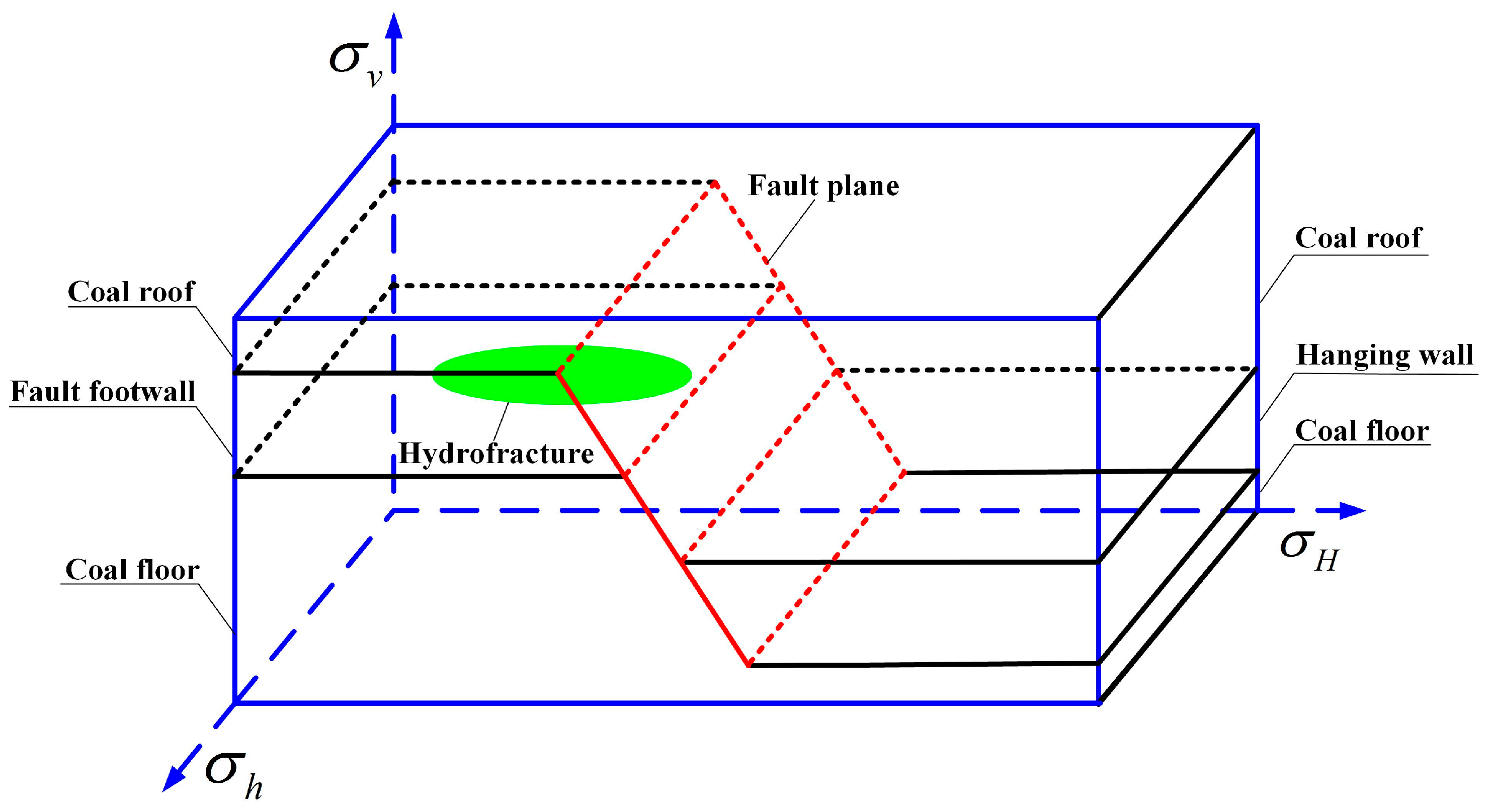
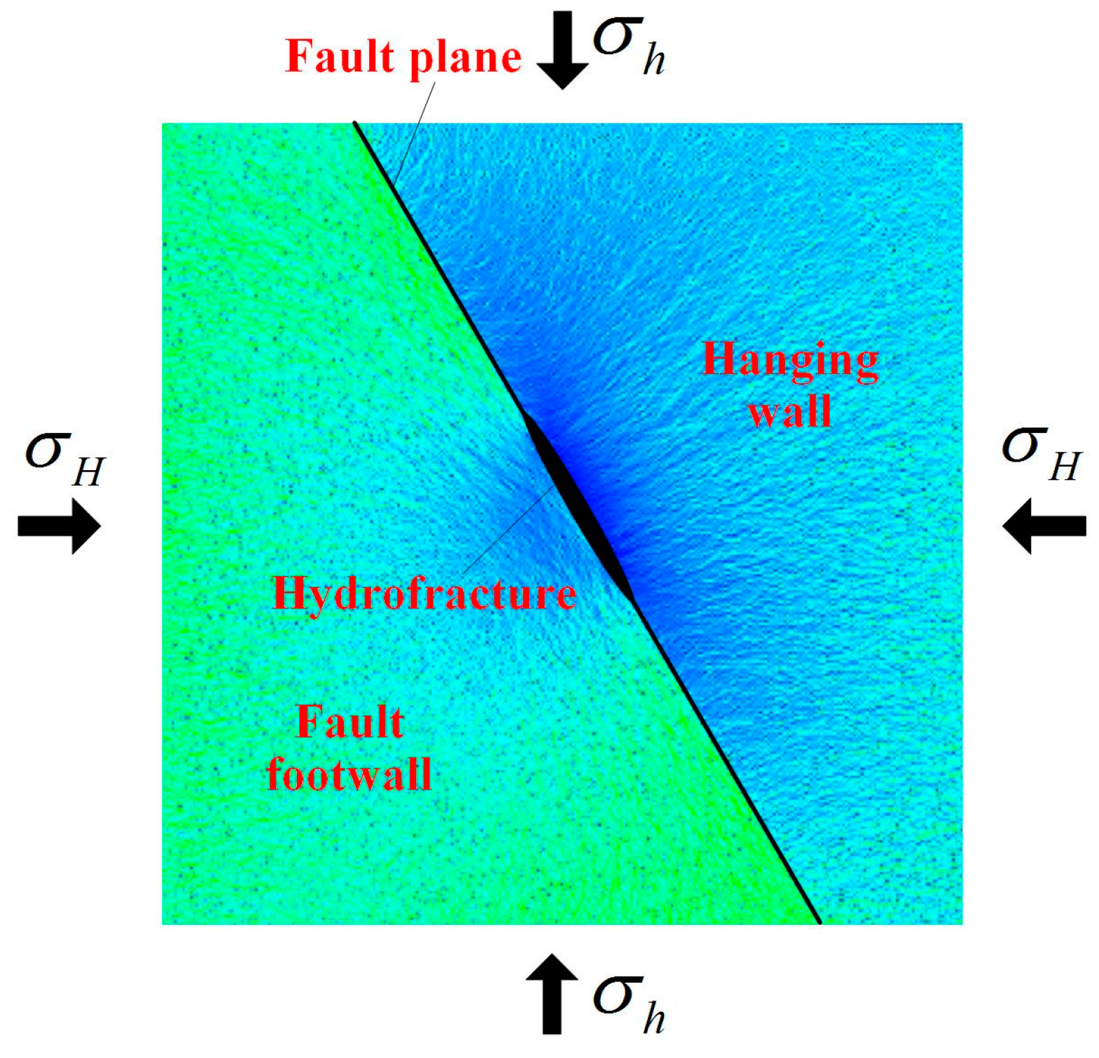
A three-dimensional model was built. As shown in Figure 1, the hydrofracture in the hanging wall of coal seam propagate towards the fault plane. is the horizontal maximum crustal stress, is the horizontal minimum crustal stress, and is the vertical crustal stress.
Three propagation modes may happen when the fracture meets a fault.
- (1)
- The fracture will directly enter into the coal roof through fault plane and continue propagating towards the direction of the horizontal maximum crustal stress;
- (2)
- Massive amounts of fracturing fluid enter the fault plane, forcing the plane to stretch by overcoming its normal stress, which causes shear damage to the ends of fault plane. The fracture propagates along the fault plane;
- (3)
- Massive amount of fracturing fluid enter the fault plane, forcing the plane to stretch, but without shear damage to its ends. The fracture enters into the hanging wall of the coal bed, effective fracturing taking place.
2.2. A Simplified Analytical Model of Hydrofracture Meeting Faults
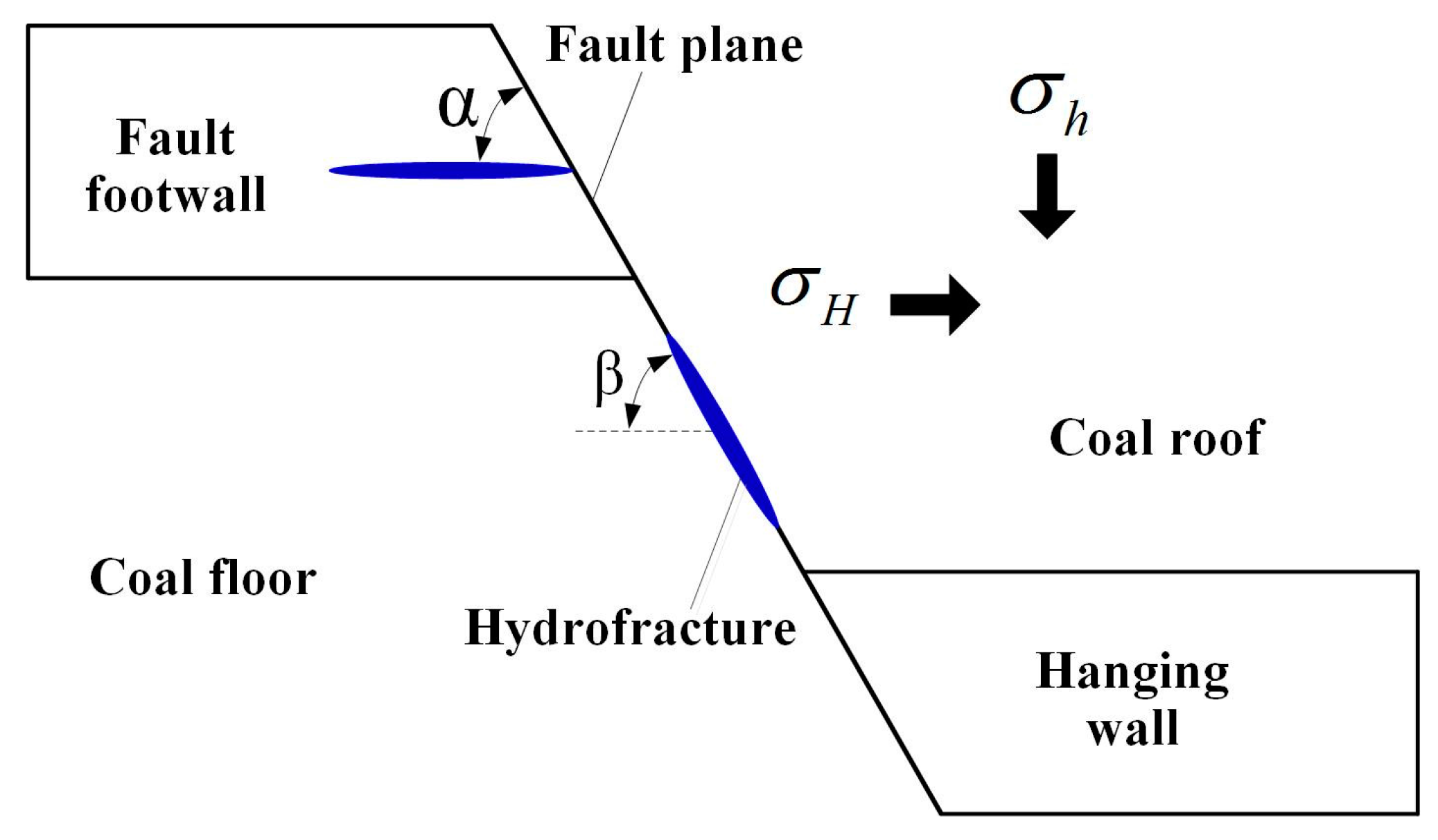
As the three-dimensional model was very complicated and too many influencing factors were involved, the three-dimensional model was converted to a two-dimensional model to study the impact of certain parameters and conditions.
As the strength of coal floor and roof is much bigger than that of coal bed, it was assumed that the fracture cannot break through the floor and roof in a vertical direction during its propagation through the coal seam. This forms an oval cross section fracture of limited height range. Therefore, without considering the propagation of the height of the fracture, a 2D model (Figure 2) of a hydrofracture meeting a fault was established, where is the intersection angle between the hydraulic fracture (the horizontal maximum crustal stress) and the fault plane, .
3. A Theoretical Analysis of Hydraulic Fractures Meeting Faults
When the hydrofracture meets a fault, its propagation direction may change in the following two situations. First, the fracture will either go through the bedding plane or propagate along it when it intersects with the plane. Second, the fracture will continue propagating along the bedding plane or into the coal bed when it propagates along the bedding plane to the coal seam of hanging wall. Therefore, the analysis of the fracture propagation was focused on two aspects: (1) Will the fault plane stretch when the hydrofracture in the footwall propagates to the fault plane? (2) Will the fault plane end suffer shear failure after it stretches?
3.1. Propagation of Hydrofracture in the Coalseam and Rock
When the hydraulic fracture propagates through the homogeneous rock, the up-down surface of the fracture will stretch symmetrically. An edge-opened crack (Mode I crack) forms. Therefore, the instability of hydraulic fracture propagation in homogeneous rock belongs to a Mode I crack problem category. Based on the Irwin crack propagation criterion, the critical water pressure of hydrofracture propagating in the coal seam, roof and floor rock can be derived [33].
In the process of a hydrofracture moving along the direction of horizontal maximum crustal stress, the fracture is only affected by the normal stress, while the shear stress remains zero. The shear stress and normal stress on the hydrofracture plane are given as follows:
According to Irwin crack propagation criterion, for Mode I cracks, the fracture will propagate when the stress intensity factor reaches the critical value :
where is the stress intensity factor of Mode I crack, and is the critical stress intensity factor (fracture toughness). is calculated as follows:
where a is the half-length of the fracture.
is related to the rock’s elasticity modulus, Poisson ratio and unit area surface energy:
where is the elasticity modulus of rock; is the surface energy per unit area, and is the Poisson ratio.
Combining (4) and (5) with (3), the critical water pressure of hydrofracture propagation can be expressed.
The critical water pressure of hydrofracture propagating in the coal seam is:
The critical water pressure of hydrofracture propagating in the roof and floor rock is:
In the above formula, , , are the elasticity modulus, surface energy of unit area, and Poisson ratio of the coal mass respectively, , , are the elasticity modulus, surface energy of unit area, and Poisson ratio of the roof and floor rock respectively, and is always bigger than .
3.2. Critical Water Pressure Causing Stretched Damage to the Fault Plane
When the hydrofracture intersects with the fault plane, the fault plane will stretch if the fluid pressure of the crack tip surpasses the normal stress of the fault plane. When the fracture does not reach the fault plane, based on two-dimension linear elastic theory, the shear stress and normal stress on the fault plane can be attained [34].
The critical water pressure causing stretched damage to the fault plane is:
3.3. Critical Water Pressure Causing Shear Damage to the Fault Plane
The overwhelming shear stress on the fault plane will easily lead to a shear slip, and the fracture will propagate towards the fault plane. According to Mohr-Coulomb strength criterion [35], the formula of stress on fault plane shall be:
where is the cohesion force of the fault plane; is the friction coefficient of the fault plane; is the normal stress on the fault plane, and is the fluid pressure on the fault plane.
If , a shear slip will happen to the fault plane.
Combining (8) and (9) with (11), the critical water pressure causing shear damage to the fault plane can be derived:
3.4. Fracture Propagation Direction
(1) When , the fault plane will not stretch when the fracture intersects with it, and the fracture will travel through the fault plane and enter into the coal roof. The following can be attained:
Under certain mechanical parameters of coal and rock mass, the fracture propagation depends largely on the horizontal crustal stress difference and intersection angle when the fracture meets the fault. The bigger the horizontal crustal stress difference and the intersection angle, the more likely the fracture directly enters through the fault plane and propagates.
(2) When and , the fault plane will stretch but suffer no shear damage after the fracture intersects with it. The fracture will propagate and enter into the hanging wall of the coal bed, forming an effective fracture. The following can be attained:
(3) When and , the fault plane will stretch and suffer shear damage after the fracture intersects with it, and the fracture will continue propagating along the fault plane. The following can be attained:
The above analysis shows that the propagation of a hydrofracture meeting the fault plane is influenced by such factors as physical and mechanics parameters of the coal and rock mass, intersection angle between the fracture and the fault plane, and horizontal crustal stress differences.
4. Numerical Simulation
Compared with similar model tests and field tests, the numerical simulation test has advantages such as visual result, low cost, and a short period of testing, contributing to its increasingly wide application in scientific studies [36,37]. A numerical simulation on the propagation rules of a hydrofracture meeting a fault plane was conducted by using the coupling system of flow and solid in the rock failure process analysis (RFPA2D-Flow).
4.1. Numerical Simulation Method
RFPA2D-Flow is a numerical simulation method based on nonlinearity, heterogeneity, and anisotropy in rock fracturing, which was developed by Dalian Mechanics Software Co. Ltd. in China [38]. Regarding the finite element theory and statistical damage theory, its calculation method takes into consideration the heterogeneity of material properties and the randomness of flow distribution, and combines the statistical distribution hypothesis to a numerical computation method (finite element method) and for material damage, identifies the units that meet a preset strength criterion, achieving a numerical simulation of the damage process heterogeneous materials.
RFPA2D-Flow is based on the following fundamental hypotheses: (1) The fluid in rock medium follows Biot Seepage Theory; (2) The rock medium is an elasto-brittle material with residual strength such that its loading and unloading process agrees with elastic damage theory; (3) The maximum tensile strength criterion and Mohr-Coulomb criterion are used as a damage threshold to judge element damage; (4) Under an elastic state, the stress-permeability coefficient relationship for material is described by a negative exponential function, and the permeability coefficient will be increased dramatically after the material is damaged; (5) The mechanical parameters of material mesostructure are assigned according to the Weibull distribution, with the purpose of bringing about material heterogeneity.
In the classic Biot seepage coupled theory, the influence of stress on rock permeability is out of consideration, as it does not meet momentum conservation. After taking the influence of stress into consideration, the coupled seepage and stress equation should be supplemented. Therefore, the RFPA2D-Flow model with damage is as follows [39]:
- (1)
- Equilibrium equation:where is the total stress in the ij-plane, and is the body force in the jth direction.
- (2)
- Geometric equation:where is normal strain, is volumetric strain, and is the displacement in the ith direction.
- (3)
- Constitutive equation:where is the effective stress in the ij-plane, is the pore-fluid pressure coefficient, is the pore-fluid pressure, is the Kronecker constant, is Lame coefficient, and is the shear modulus.
- (4)
- Seepage equation:where is the permeability coefficient, and represents Laplace operator.
- (5)
- Coupled seepage and stress equation:where is the initial-value of seepage coefficient, is the mutation ratio of seepage coefficient, and is the coupling coefficient (stress sensitivity factor).
The element will start to damage, as long as the stress state or strain state of element satisfies some given damage thresholds. The elastic modulus of the element may degrade gradually as damage progresses and the elasticity modulus of the damaged element is:
where and represent the elasticity moduli of the damaged element and the non-damaged element respectively. is the damage variable.
RFPA2D-Flow can be used to analyze the hydrofracturing process of permeable and heterotypical rock, which can meet the needs of numerical simulation calculation on the propagation of a hydrofracture meeting a fault.
4.2. Acquisition of Numerical Simulation Parameters
Massive quantities of coal, and roof and floor rocks were chosen as samples from working face 1315 of the Zhonagliangshan coal mine in Chongqing city, China. The samples were transported to the lab and cut into φ 50 mm × 100 mm standard test specimens. By the uniaxial and triaxial compression experiments, physical and mechanics parameters were attained, as shown in Table 1.
The field test showed that the crustal stress of working face 1315 was between 8 MPa and 14 MPa. Therefore, the minimum horizontal crustal stress in the numerical simulation was set to 8 MPa, while the maximum was set to 10, 12 and 14 MPa.
4.3. Model Building and Scheme Design
Since it was impossible to simulate the whole process of the hydrofracture propagating into the hanging wall from the footwall and bedding plane, the numerical simulation was divided into two parts: (1) The propagation of the fracture meeting a fault; (2) The propagation of the fracture in the fault plane.
4.3.1. Propagation of the Hydrofracture Meeting the Fault Plane
(1) Model Building
A numerical analysis model was established as shown in Figure 3, with a 10 m × 10 m model area divided into 300 × 300 = 90,000 units. In Figure 3, the blue section represents the coal bed, the green for the roof and the oval, whose long axis is 1 m with a minor axis of 0.2 m, for the hydrofracture. The interface between the two was the fault plane.
The horizontal crustal stress on the model was imposed on its periphery in the way of a displacement boundary condition. The maximum horizontal crustal stress was imposed on the left and right sides of the model, and the minimum horizontal crustal stress was imposed on the top and bottom sides. Water pressure was injected on the internal face of the hydrofracture, with the initial pressure being 10 MPa and a single incremental quantity being 0.2 MPa.
(2) Numerical Simulation Scheme Design
To assess the impact of horizontal crustal stress difference and the intersection angle between hydrofracture and fault plane on the fracture propagation, 12 groups of numerical simulations were conducted, as shown in Table 2.
4.3.2. Propagation of the Hydrofracture in the Fault Plane
(1) Model Building
On the condition that the footwall hydrofracture propagates along the fault plane after their meeting, the hydrofracture will continue its propagation along the fault plane or propagate into the hanging wall. A numerical analysis model was built, as shown in Figure 4, whose area was 10 m × 10 m and divided into 300 × 300 = 90,000 units. In Figure 4, the blue section represents the coal bed, the green for its floor. The interface between the two is the fault plane, on which an oval with a 1 m long axis and a 0.2 m minor axis represents the hydrofracture.
(2) Numerical Simulation Scheme Design
To assess the impact of horizontal stress difference and the dip angle of the fault plane on fracture propagation, 14 groups of numerical simulations were conducted, as shown in Table 3.
4.4. Analysis of the Numerical Simulation Results
4.4.1. Propagation of the Hydrofracture Meeting the Fault Plane
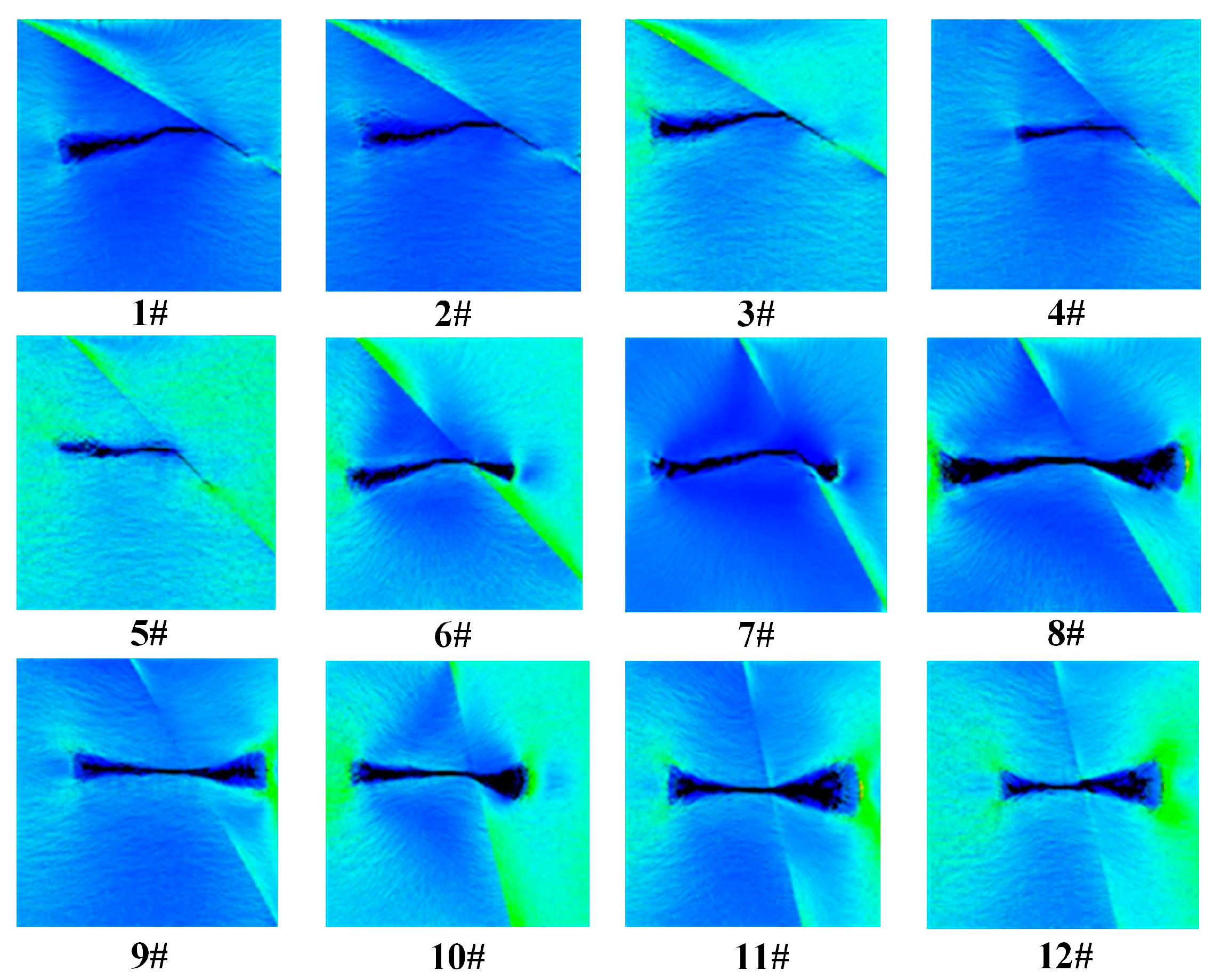
The numerical simulation results are shown in Figure 5.
(1) Impact of the Horizontal Crustal Stress Difference
When the intersection angle between the fracture and the fault plane is 30°, the fracture will propagate along the fault plane after the two meet. A Small impact was detected for the horizontal crustal stress difference on fracture propagation. When the intersection angle reaches 45° and the stress difference is 2 MPa and 4 MPa, the fracture propagates along the fault plane after the two meet. However, when the stress difference reaches 6 MPa, the fracture will pass through the bedding plane and propagate. The fracture will propagate through the fault plane after the two meet, when the intersection angle is 60° and 75°. It is more probable for the fracture to go through the bedding plane as the stress difference increases. Thus, with certain intersection angles, the bigger the stress difference, the more likely the fracture will pass through the bedding plane for propagation.
(2) Impact of Intersection Angle between the Hydrofracture and the Fault Plane
When the horizontal crustal stress difference is 2 MPa and the intersection angle is 30° and 45°, the fracture will propagate along the bedding plane. However, if the intersection angle reaches 60°, the fracture will propagate along the bedding plane for a certain distance, and then travel through it for further movement. After the intersection angle reaches 75°, the fracture will propagate through the bedding plane directly.
When the stress difference is 4 MPa and the intersection angle is 30° and 45°, the fracture will propagate along the bedding plane. But if the intersection angle is 60° and 75°, the fracture will pass through the bedding plane for propagation. When the stress difference is 6 MPa and the intersection angle is 30°, the fracture will propagate along the bedding plane, but it will go through the bedding plane for propagation if the angle is over 45°.
The fracture is more likely to go through the bedding plane for propagation at the intersection angles of 60° and 75° than at 45°. Therefore, with certain stress differences, the bigger the intersection angle, the more likely the fracture will pass through the bedding plane.
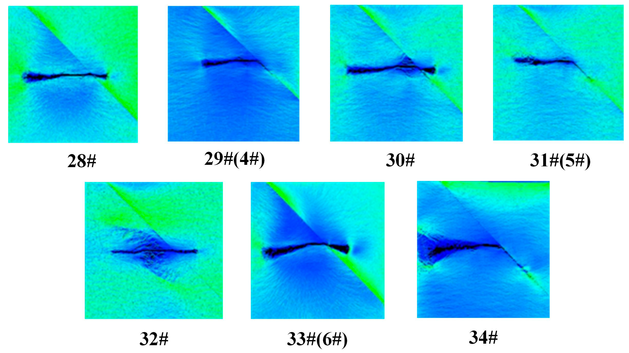
(3) Impact of Elasticity Modulus of the Coal Roof
According to Formula (2), elasticity modulus of the coal roof has a direct impact on the critical water pressure of the hydrofracture propagating through the roof, changing the propagating rules of the fracture. To study the impact of the elasticity modulus of the coal roof on the hydrofracture propagation, and based on the groups 4#, 5#, 6# numerical simulation results, a numerical simulation project as shown in Table 4 was built, with other parameters remaining constant.
The numerical simulation results are shown as Figure 6. When given a stress difference of 2 MPa and a roof elasticity modulus of 25 MPa, the hydrofracture will penetrate the bedding plane and propagate; however, when the roof elasticity modulus reaches 30 MPa, the fracture will propagate along the bedding plane after meeting it. The propagation rules of the fracture at the stress difference of 4 MPa are quite close to those at 2 MPa. But when the stress difference is 6 MPa and elasticity modulus of roof strata increases to 35 MPa from 25 MPa, the fracture will gradually propagate along the bedding plane rather than directly penetrating it. Therefore, a bigger roof elasticity modulus reduces the chances for the fracture to enter the roof through the bedding plane, thus making it easier to propagate along the bedding plane.
4.4.2. Numerical Simulation of a Hydrofracture Propagating in the Fault Plane
The numerical simulation results are shown as Figure 7. Under different horizontal crustal stress differences and dip angles of the fault plane, the initial position of the hydrofracture will change, but all fractures are able to propagate into the hanging wall. With the dip angle of the fault plane being 45° or below, the initial position will be the two fracture tips, one propagating into the coal seam, while the other moves along the bedding plane. With the increase of the dip angle as well as the stress difference, the trend that the fracture moves into the coal bed becomes increasingly evident. With the increase of crustal stress differences, the fracture moves into the coal seam and the floor, instead of propagating along the bedding plane. When the stress difference is 6 MPa, the fracture will start from the middle of the fracture and enter into the coal seam. With the dip angle being 75°, the initial position of the fracture will be at the middle and tip points of the fracture, and then will enter the underlying coal seam and the floor, particularly into the coal seam. With the increase of dip angle and crustal stress difference, it is more likely for the fracture to propagate into the coal seam and floor. When the dip angle of the fault plane and crustal stress difference increase to 60° and 6 MPa respectively, or the dip angle increases to 75°, the fracture will start from the tip points and the middle of the fracture, rather than the tip alone.
5. Field Test and Discussion
5.1. Field Test
The 1315 working face lies 210–280 m underground between rock cross-cuts 5 and 6 in the southwest section of the coal mine. The intake level is 280 m, while the transportation as well as air-return level is 210 m. This working face, with a strike length of 282 m and an inclination length of 74 m, belongs to coal bed K1. It is 2.2 m in thickness. In the opening up phase of the working face, many fault planes were disclosed, most of which were normal faults. We chose the air-return way of the working face as the position for the field test, and the fault section F3 for the field trial. Parameters of F3 are shown in Table 5. As can be seen from Figure 8, F3 on the side of the air-return way 1315 is 81 m away from the open-off cut, and 96 m away from the cut on the side of the air intake way.
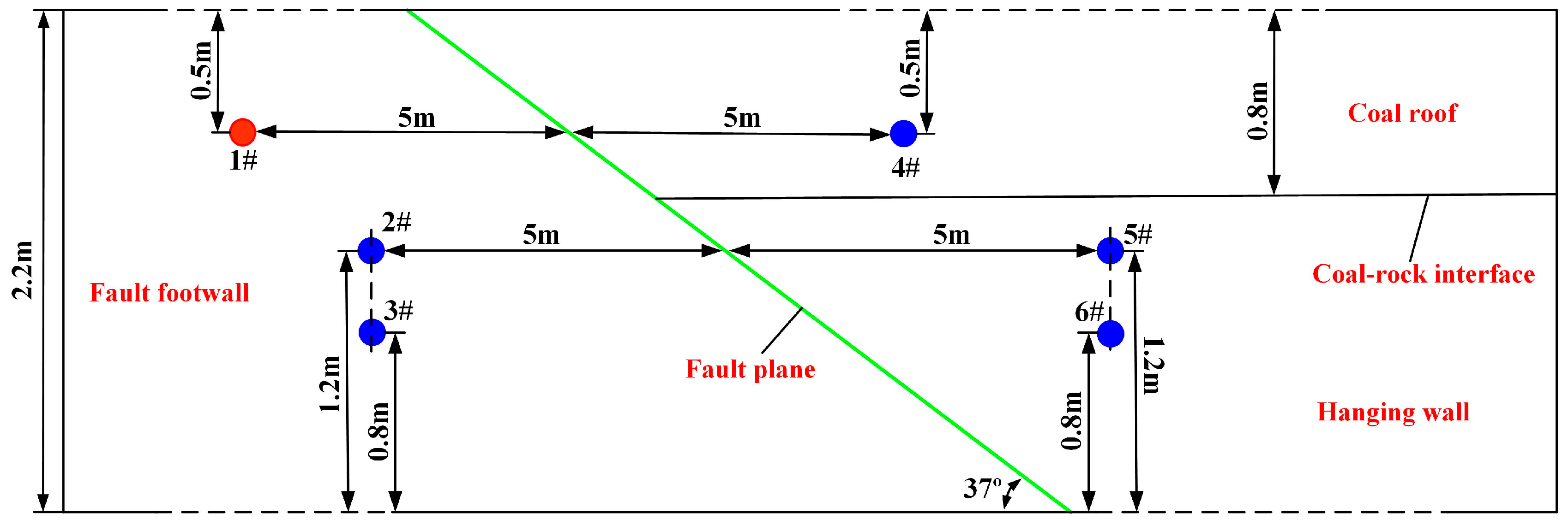
As shown in Figure 9, the drillings were constructed in the dip direction of the coal seam. On the right and left sides of the fault plane, 6 horizontal boreholes were drilled, whose drilling depth was 30 m and drilling diameter was 75 mm. Among the holes, 1#~3# were located in the footwall of the coal seam, 4# in the coal roof, and 5# and 6# in the hanging wall. 1# was the fractured hole while 2#~6# were the checking holes.
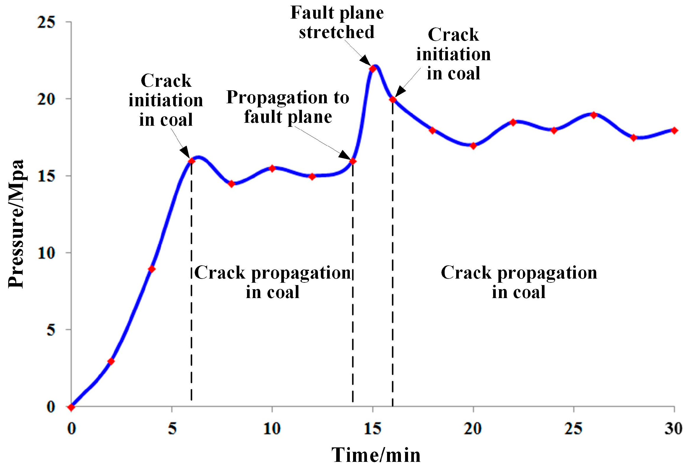
Hole 1#, with a hole-sealing depth of 20 m, was fractured 48 hr after it was sealed. During the fracturing period, checking holes 2#~6# were inspected and it was found that no water flowed from holes 3# and 4#. In contrast, lots of water in a period of 25–26 min was detected in holes 2# and 5#, while a small amount of water was seen flowing from hole 6# at 28 min. This means that the hydrofracture does not enter the coal roof after it meets the fault plane; instead, it propagates along the fault plane into the coal seam on both sides of the fault plane, which was the same as the theoretical analysis and numerical simulation results. The fracture curve is demonstrated in Figure 10, from which the propagation process of the hydrofracture can be deduced.
With the fracturing pump opened, pressure increased, and the fracture began to crack at 6 min, with an initial fracture pressure of 15 MPa. In the period between 6 min and 14 min, the propagation pressure of the fracture in the coal seam ranged from 14 MPa to 16 MPa. At 14 min, the fracture propagated to the fault plane, with water pressure rising as well. At 15 min, the fault plane stretched and pressure at this time was 22 MPa. At 16 min, the fracture moved along the fault plane to the coal seam of the hanging wall, then propagated into it. Propagation pressure in the coal seam of the hanging wall ranged between 17 MPa and 19 MPa.
5.2. Discussion
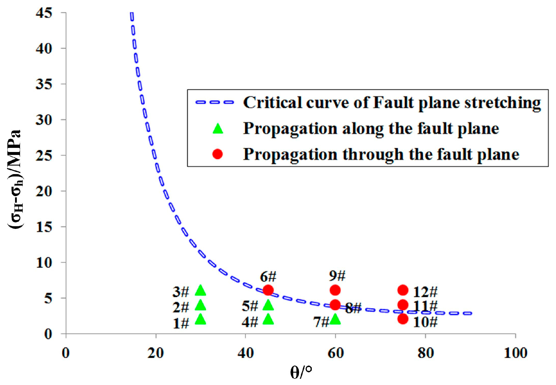
(1) According to the geological data and the measured parameters of the working face, we choose 0.8 as the fault plane friction coefficient, 1 m as the fracture half-length, and 0.0004 (MPa·m) as the fracture surface energy. Bringing these data into the Formula (8) leads to the critical curve of the stretched fault plane (Figure 11), which was then analyzed together with the numerical simulation results. When the coordinates of the dip angle of the fault plane and the horizontal crustal stress difference lie in the upside section of the critical curve, the fracture will go through the fault plane and propagate. However, it will propagate along the fault plane when the coordinates lie in the downside section. The bigger the intersection angle between the fracture and the fault plane and the horizontal crustal stress difference, the more easily the fracture goes through the fault plane and propagates into the coal roof. Meanwhile, compared to the horizontal crustal stress difference, the intersection angle exerts more impact on the fracture propagation direction. Numerical simulation results were quite consistent with the theoretical analysis.
(2) When the intersection angle between the fracture and the fault plane surpasses 45°, the likelihood of the hydrofracture in the footwall to propagate along the bedding plane is reduced, while the likelihood of propagating into the coal roof increases. The difficulty of the fracture propagating into the hanging wall made it impossible to effectively fracture the coal seam. However, numerical simulation results showed that the hydrofracture set in the bedding plane was able to relatively easily enter into the hanging wall. Therefore, on the condition that the fault plane dip angle was over 45°, to achieve the effective fracture, fracturing could be carried out on the fault plane or in the hanging wall of the coal seam.
(3) With the increase of the fault plane dip angle and the horizontal crustal stress difference, the tendency of the fracture moving along the bedding plane decreased, and it was quite easy for the fracture to enter the coal floor and roof. Thus, the fracture scheme should be optimized in order to reduce damage to the floor and roof by fractures. Meanwhile, the support measures should be strengthened to ensure the safe production of the working face.
6. Conclusions
(1) Faults in the coal seam have a significant impact on hydrofracture propagation, as shown in following aspects: the intersection between the fracture and the fault plane, the dip angle of fault plane, horizontal crustal stress difference, and the physical and mechanical properties of the coal-rock bed.
(2) Upon intersecting between the fracture and fault plane, the hydrofracture is more likely to directly propagate through the fault plane, with the increase of the horizontal crustal stress difference and the intersection angle. The possibility of the hydrofracture propagating along the fault plane increases as the elasticity modulus of the coal floor and roof aggrandize. With the increase of the fault plane dip angle and the horizontal crustal stress difference, it is more likely for the hydrofracture in the fault plane to propagate into the hanging wall and the floor, and the initial crack position will obviously change.
(3) When the dip angle of fault plane is less than 45°, the fracture at the footwall can enter the hanging wall along the fault plane. However, when the fault plane dip angle is more than 45°, the likelihood of the fracture to propagate along the fault plane is reduced, making it difficult to effectively fracture the hanging wall coal seam. Since the fracture in the fault plane can easily get into the hanging wall, we should initiate fracturing in the fault plane, or fracture the hanging wall coal bed directly.
(4) As it is easy for the fracture to propagate into the coal floor and roof when the fault plane dip angle and horizontal crustal stress difference are both quite big, protection measures should be taken for the floor and roof. At the same time, the fracture scheme should be adjusted in order to reduce the damage imposed on the floor and roof by hydraulic fracturing.
Acknowledgments
This paper is jointly supported by the Program for Changjiang Scholars and Innovative Research Team in University of China (No. IRT13043) and the National Science Foundation of China (No. 51374258).
Author Contributions
Haiyang Wang, Binwei Xia and Yiyu Lu contributed to developing the mathematical model, designing the simulation scheme and writing the paper; Tao Gong and Rui Zhang performed the numerical simulation and field test.
Conflicts of Interest
The authors declare no conflict of interest.
References
- Beaton, A.; Langenberg, W.; Pană, C. Coalbed methane resources and reservoir characteristics from the Alberta Plains, Canada. Int. J. Coal Geol. 2006, 65, 93–113. [Google Scholar] [CrossRef]
- Senthamaraikkannan, G.; Gates, I.; Prasad, V. Development of a multiscale microbial kinetics coupled gas transport model for the simulation of biogenic coalbed methane production. Fuel 2016, 167, 188–198. [Google Scholar] [CrossRef]
- Lu, Y.Y.; Zuo, S.J.; Ge, Z.L.; Xiao, S.Q. Experimental Study of Crack Initiation and Extension Induced by Hydraulic Fracturing in a Tree-Type Borehole Array. Energies 2016, 9, 514. [Google Scholar] [CrossRef]
- Wang, H.Y.; Xia, B.W.; Lu, Y.Y.; Ge, Z.L.; Tang, J.R. Experimental study on sonic vibrating effects of cavitation water jets and its promotion effects on coalbed methane desorption. Fuel 2016, 185, 468–477. [Google Scholar] [CrossRef]
- Skoczylas, N. Laboratory study of the phenomenon of methane and coal outburst. Int. J. Rock Mech. Min. Sci. 2012, 55, 102–107. [Google Scholar] [CrossRef]
- Wang, G.; Li, W.X.; Wang, P.F.; Yang, X.X.; Zhang, S.T. Deformation and gas flow characteristics of coal-like materials under triaxial stress conditions. Int. J. Rock Mech. Min. Sci. 2017, 91, 72–80. [Google Scholar] [CrossRef]
- Ding, Y.L.; Dou, L.M.; Cai, W.; Chen, J.J.; Kong, Y.; Su, Z.G.; Li, Z.L. Signal characteristics of coal and rock dynamics with micro-seismic monitoring technique. Int. J. Min. Sci. Technol. 2016, 26, 683–690. [Google Scholar] [CrossRef]
- Dai, S.F.; Ren, D.Y.; Chou, C.L.; Finkelman, R.B.; Seredin, V.V.; Zhou, Y.P. Geochemistry of trace elements in Chinese coals: A review of abundances, genetic types, impacts on human health, and industrial utilization. Int. J. Coal Geol. 2011, 94, 3–21. [Google Scholar] [CrossRef]
- Yi, L.J.; Yu, Q.X. Numerical Test of Gas Pre-drainage with Dense Boreholes in Outburst Coal Seam. Coal Saf. 2010, 2, 1–4. [Google Scholar]
- Wu, Q.; Yin, W.; Yan, H.; Wang, D.S.; Wang, Z.P.; Yang, B.S. Technical Research on Gas Outburst Disaster Control in Crumby Low-permeability Coal Seam. Disa Adv. 2013, 6, 163–171. [Google Scholar]
- Zou, Q.L.; Lin, B.Q.; Liu, T.; Zhou, Y.; Zhang, Z.; Yan, F.Z. Variation of methane adsorption property of coal after the treatment of hydraulic slotting and methane predrainage: A case study. J. Nat. Gas Sci. Eng. 2014, 20, 396–406. [Google Scholar] [CrossRef]
- Lu, Y.Y.; Cheng, L.; Ge, Z.L.; Xia, B.W.; Li, Q.; Chen, J.F. Analysis on the initial cracking parameters of cross-measure hydraulic fracture in underground coal mines. Energies 2015, 8, 6977–6994. [Google Scholar] [CrossRef]
- You, Q.; Wang, C.Y.; Ding, Q.F.; Zhao, G.; Fang, J.C.; Liu, Y.F.; Zhao, M.W.; Dai, C.L.; Geng, M. Impact of surfactant in fracturing fluid on the adsorption–desorption processes of coalbed methane. J. Nat. Gas Sci. Eng. 2015, 26, 35–41. [Google Scholar] [CrossRef]
- Huang, B.X.; Cheng, Q.Y.; Chen, S.L. Phenomenon of methane driven caused by hydraulic fracturing in methane-bearing coal seams. Int. J. Min. Sci. Technol. 2016, 26, 919–927. [Google Scholar] [CrossRef]
- He, J.M.; Lin, C.; Li, X.; Wan, X.L. Experimental investigation of crack extension patterns in hydraulic fracturing with shale, sandstone and granite cores. Energies 2016, 9, 1018. [Google Scholar] [CrossRef]
- Jiang, T.T.; Zhang, J.H.; Wu, H. Experimental and numerical study on hydraulic fracture propagation in coalbed methane reservoir. J. Nat. Gas Sci. Eng. 2016, 35, 455–467. [Google Scholar] [CrossRef]
- Chen, M.; Jin, Y.; Zhang, G.Q. Petroleum Engineering Rock Mechanics; Science Press: Beijing, China, 2008; pp. 162–163. [Google Scholar]
- Zou, Y.S.; Ma, X.F.; Zhang, S.C.; Zhou, T.; Li, H. Numerical Investigation into the influence of bedding plane on hydraulic fracture network propagation in shale formations. Rock Mech. Rock Eng. 2016, 49, 3597–3614. [Google Scholar]
- Taheri-Shakib, J.; Ghaderi, A.; Hosseini, S.; Hashemi, A. Debonding and coalescence in the interaction between hydraulic and natural fracture: Accounting for the effect of leak-off. J. Nat. Gas Sci. Eng. 2016, 36, 454–462. [Google Scholar] [CrossRef]
- Shi, X.Y.; Wen, G.J.; Bai, J.H.; Xu, X.J. A physical simulation experiment on fracture propagation of coal petrography in hydraulic fracturing. J. China Coal Soc. 2016, 41, 1145–1151. [Google Scholar]
- Warpinski, N.R.; Teufel, L.W. Influence of geologic discon tinuities on hydraulic fracture propagation. J. Pet. Technol. 1984, 39, 209–220. [Google Scholar] [CrossRef]
- Blanton, T.L. Propagation of hydraulically and dynamically induced fractures in naturally fractured reservoirs. In Proceedings of the Society of Petroleum Engineers Unconventional Gas Technology Symposium, Louisville, KY, USA, 18–21 May 1986. [Google Scholar]
- Zhou, J.; Chen, M.; Jin, Y.; Zhang, G.Q. Analysis of fracture propagation behavior and fracture geometry using a tri-axial fracturing system in naturally fractured reservoirs. Int. J. Rock Mech. Min. Sci. 2008, 45, 1143–1152. [Google Scholar] [CrossRef]
- Song, C.P.; Lu, Y.Y.; Xia, B.W.; Hu, K. Effects of natural fractures on hydraulic fractures propagation of coal seams. J. Northeast. Univ. 2014, 35, 756–760. [Google Scholar]
- Zhang, Z.; Ghassemi, A. Simulation of hydraulic fracture propagation near a natural fracture using virtual multidimensional internal bonds. Int. J. Numer. Methods Fluids 2011, 35, 480–495. [Google Scholar] [CrossRef]
- Anderson, G.D. Effects of friction on hydraulic fracture growth near unbonded interfaces in rocks. Soc. Pet. Eng. J. 1981, 21, 21–29. [Google Scholar] [CrossRef]
- Heuzé, F.E. An overview of projectile penetration into geological materials, with emphasis on rocks. Int. J. Rock Mech. Min. Sci. 1990, 27, 1–14. [Google Scholar] [CrossRef]
- Zhao, H.; Chen, M. Extending behavior of hydraulic fracture when reaching formation interface. J. Pet. Sci. Technol. 2010, 74, 26–30. [Google Scholar] [CrossRef]
- Lu, Y.Y.; Song, C.P.; Jia, Y.Z.; Xia, B.W.; Ge, Z.L.; Tang, J.R.; Li, Q. Analysis and numerical simulation of hydraulic fracture crack propagation in coal-rock bed. Comput. Model. Eng. Sci. 2015, 105, 69–86. [Google Scholar]
- Zhao, Z.H.; Li, X.; Wang, Y.; Zheng, B.; Zhang, B. A Laboratory Study of the Effects of Interbeds on Hydraulic Fracture Propagation in Shale Formation. Energies 2016, 9, 556. [Google Scholar] [CrossRef]
- Lu, Y.Y.; Cheng, Y.G.; Ge, Z.L.; Cheng, L.; Zuo, S.J.; Zhong, J.Y. Determination of Fracture Initiation Locations during Cross-Measure Drilling for Hydraulic Fracturing of Coal Seams. Energies 2016, 9, 358. [Google Scholar] [CrossRef]
- Zhang, X.; Jeffrey, R.G. Fluid-driven nucleation and propagation of splay fractures from a permeable fault. J. Geophys. Res. Solid Earth 2016, 121, 5257–5277. [Google Scholar] [CrossRef]
- Song, C.P.; Lu, Y.Y.; Jia, Y.Z.; Xia, B.W. Effect of coal-rock interface on hydraulic fracturing propagation approach. J. Northeast. Univ. 2014, 35, 1340–1345. (In Chinese) [Google Scholar]
- Zhu, Z.D.; Guo, H.Q. Hydraulic Foundation of Fractured Rock Mass; Higher Education Press: Beijing, China, 2007; pp. 52–53. [Google Scholar]
- Cai, M.F.; He, M.C.; Liu, D.Y. Rock Mechanics and Engineering; Higher Education Press: Beijing, China, 2002; pp. 93–94. [Google Scholar]
- Zhou, L.; Hou, M.Z. A new numerical 3D-model for simulation of hydraulic fracturing in consideration of hydro-mechanical coupling effects. Int. J. Rock Mech. Min. Sci. 2013, 60, 370–380. [Google Scholar] [CrossRef]
- Wang, Y.; Li, X.; Hu, R.L.; Ma, C.F.; Zhao, Z.H.; Zhang, B. Numerical evaluation and optimization of multiple hydraulically fractured parameters using a flow-stress-damage coupled approach. Energies 2016, 9, 325. [Google Scholar] [CrossRef]
- Tang, C.A.; Tham, L.G.; Lee, P.K.K. Coupled analysis of flow, stress and damage (FSD) in rock failure. Int. J. Rock Mech. Min. Sci. 2002, 39, 477–489. [Google Scholar] [CrossRef]
- Yang, T.H.; Tham, L.G.; Tang, C.A.; Liang, Z.Z.; Tsui, Y. Influence of heterogeneity of mechanical properties on hydraulic fracturing in permeable rocks. Rock Mech. Rock Eng. 2004, 37, 251–275. [Google Scholar] [CrossRef]
Figure 1.
3D model of hydrofracture meeting a fault.

Figure 2.
2D model of a hydrofracture meeting a fault.

Figure 3.
Numerical analysis model of a hydrofracture meeting the fault plane.
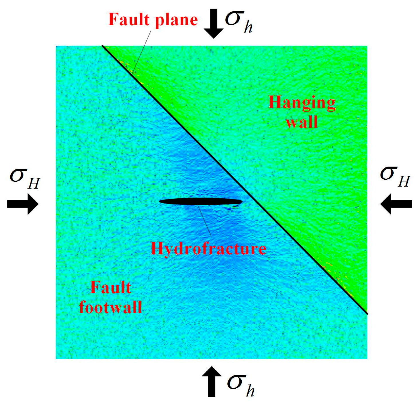
Figure 4.
Numerical analysis model of a hydrofracture propagating in the fault plane.

Figure 5.
Numerical simulation of hydrofracture propagation meeting the fault plane.

Figure 6.
Numerical simulation results for the impact of the elasticity modulus of coal roof.

Figure 7.
Numerical simulation results of a hydrofracture propagating in the fault plane.
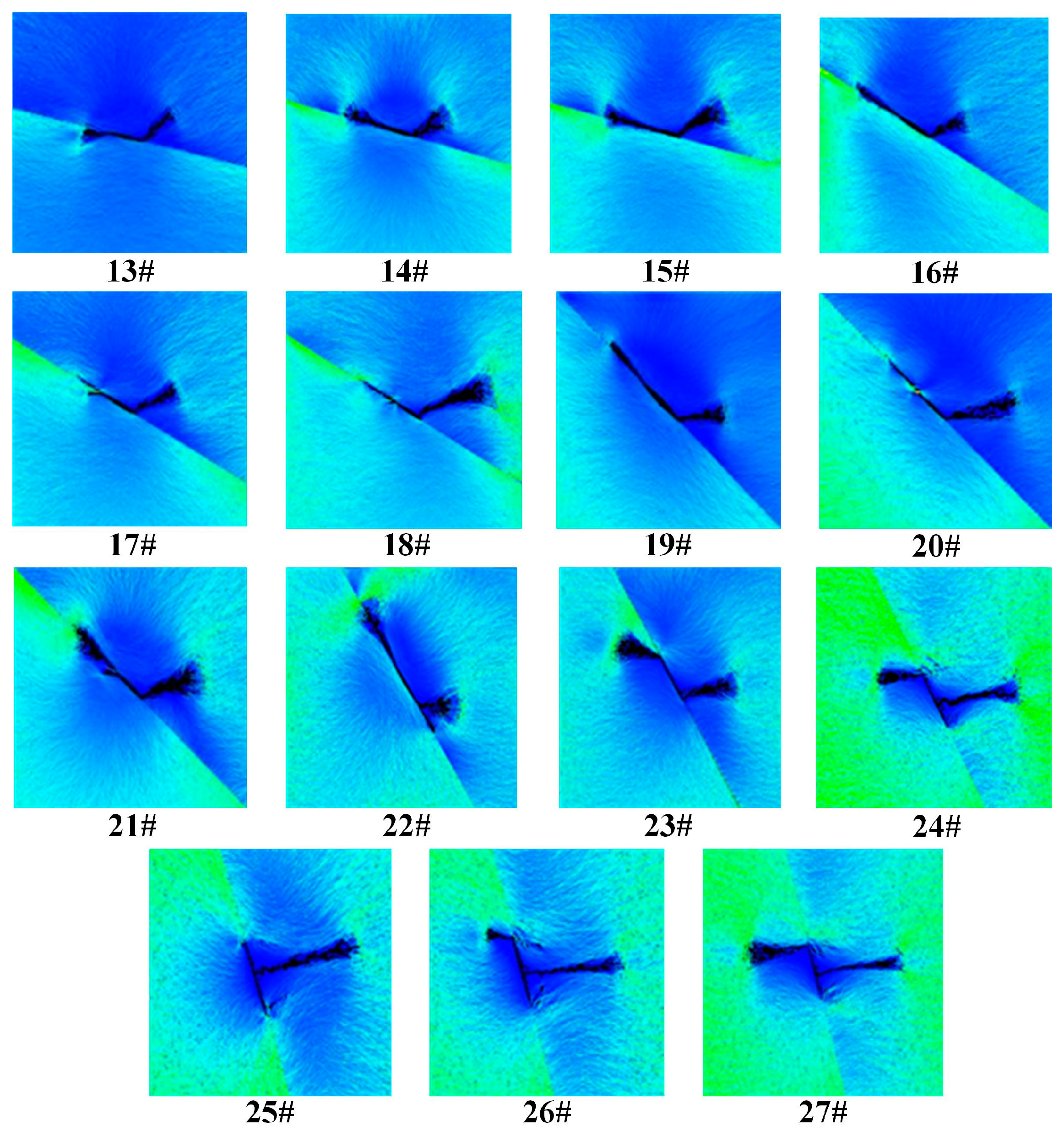
Figure 8.
Sketch map of the F3 fault position in working face 1315.

Figure 9.
Field test arrangement.

Figure 10.
The fracture curve of hole 1#.

Figure 11.
Critical curve of the stretched fault plane.


Table 1.
Physical and mechanics parameters of the coal mass, roof and floor rocks.
| Parameter | Elasticity Modulus/GPa | Poisson’s Ratio | Uniaxial Compressive Strength/MPa | Internal Friction Angle/(°) |
|---|---|---|---|---|
| Coal Mass | 1.7 | 0.33 | 15 | 30 |
| Roof and Floor | 30 | 0.22 | 40 | 30 |
Table 2.
Numerical simulation scheme of hydrofracture meeting fault plane.
| No. | /MPa | /MPa | /(°) | /MPa |
|---|---|---|---|---|
| 1# | 10 | 8 | 30 | 2 |
| 2# | 12 | 8 | 30 | 4 |
| 3# | 14 | 8 | 30 | 6 |
| 4# | 10 | 8 | 45 | 2 |
| 5# | 12 | 8 | 45 | 4 |
| 6# | 14 | 8 | 45 | 6 |
| 7# | 10 | 8 | 60 | 2 |
| 8# | 12 | 8 | 60 | 4 |
| 9# | 14 | 8 | 60 | 6 |
| 10# | 10 | 8 | 75 | 2 |
| 11# | 12 | 8 | 75 | 4 |
| 12# | 14 | 8 | 75 | 6 |
Table 3.
Numerical simulation scheme of a hydrofracture propagating on the fault plane.
| No. | /MPa | /MPa | /(°) | /MPa |
|---|---|---|---|---|
| 13# | 10 | 8 | 15 | 2 |
| 14# | 12 | 8 | 15 | 4 |
| 15# | 14 | 8 | 15 | 6 |
| 16# | 10 | 8 | 30 | 2 |
| 17# | 12 | 8 | 30 | 4 |
| 18# | 14 | 8 | 30 | 6 |
| 19# | 10 | 8 | 45 | 2 |
| 20# | 12 | 8 | 45 | 4 |
| 21# | 14 | 8 | 45 | 6 |
| 22# | 10 | 8 | 60 | 2 |
| 23# | 12 | 8 | 60 | 4 |
| 24# | 14 | 8 | 60 | 6 |
| 25# | 10 | 8 | 75 | 2 |
| 26# | 12 | 8 | 75 | 4 |
| 27# | 14 | 8 | 75 | 6 |
Table 4.
Numerical simulation scheme for impact of elasticity modulus of the coal roof.
| No. | /MPa | /MPa | /MPa | /MPa |
|---|---|---|---|---|
| 28# | 10 | 8 | 2 | 25 |
| 29# (4#) | 10 | 8 | 2 | 30 |
| 30# | 12 | 8 | 4 | 25 |
| 31# (5#) | 12 | 8 | 4 | 30 |
| 32# | 14 | 8 | 6 | 25 |
| 33# (6#) | 14 | 8 | 6 | 30 |
| 34# | 14 | 8 | 6 | 35 |
Table 5.
Parameters of fault F3.
| Fault Type | Strike | Inclination | Dip Angle/° | Fall/m | Extended Length/km |
|---|---|---|---|---|---|
| Normal Fault | NNE | NWW | 37 | 0.6–1.2 | 1.5 |
© 2017 by the authors. Licensee MDPI, Basel, Switzerland. This article is an open access article distributed under the terms and conditions of the Creative Commons Attribution (CC BY) license (http://creativecommons.org/licenses/by/4.0/).
Share and Cite
MDPI and ACS Style
Wang, H.; Xia, B.; Lu, Y.; Gong, T.; Zhang, R. Study on the Propagation Laws of Hydrofractures Meeting a Faulted Structure in the Coal Seam. Energies 2017, 10, 654. https://doi.org/10.3390/en10050654
AMA Style
Wang H, Xia B, Lu Y, Gong T, Zhang R. Study on the Propagation Laws of Hydrofractures Meeting a Faulted Structure in the Coal Seam. Energies. 2017; 10(5):654. https://doi.org/10.3390/en10050654
Chicago/Turabian StyleWang, Haiyang, Binwei Xia, Yiyu Lu, Tao Gong, and Rui Zhang. 2017. "Study on the Propagation Laws of Hydrofractures Meeting a Faulted Structure in the Coal Seam" Energies 10, no. 5: 654. https://doi.org/10.3390/en10050654
Note that from the first issue of 2016, this journal uses article numbers instead of page numbers. See further details here.