
Coordinated Control Strategy for a Hybrid Wind Farm with DFIG and PMSG under Symmetrical Grid Faults

1
State Key Laboratory of Power Transmission Equipment & System Security and New Technology, School of Electrical Engineering, Chongqing University, Chongqing 400044, China
2
Department of Electrical and Computer Engineering, Wayne State University, Detroit, MI 48202, USA
*
Author to whom correspondence should be addressed.
Energies 2017, 10(5), 669; https://doi.org/10.3390/en10050669
Submission received: 5 March 2017
/
Revised: 29 April 2017
/
Accepted: 8 May 2017
/
Published: 11 May 2017
(This article belongs to the Special Issue Wind Turbine 2017)
Abstract
:This paper presents a coordinated control strategy for a hybrid wind farm with doubly-fed induction generator (DFIG)- and direct-driven permanent-magnet synchronous generator (PMSG)-based wind turbines under symmetrical grid faults. The proposed low-voltage ride-through (LVRT) strategy is based on a novel current allocation principle and is implemented for individual DFIG- or PMSG-based wind turbines. No communication equipment between different wind power generators is required. By monitoring the local voltages and active power outputs of the corresponding wind generators, the proposed control strategy can control the hybrid wind farm to provide the maximum reactive power to support the grid voltage during a symmetrical grid fault. As a result, the reduction in the active power output from the hybrid wind farm can be decreased, which also helps avoid generator over-speed issues and supply active power support for the power grid. In addition, the reactive current upper limits of DFIG- and PMSG-based sub-wind farms are investigated by considering different active power outputs and different grid voltage dip depths, and the feasible regions of the two types of sub-wind farms for meeting the LVRT requirements are further studied. Finally, the effectiveness of the proposed coordinated LVRT control strategy for the hybrid wind farm is validated by simulation and experimental results.
1. Introduction
With wind energy penetration levels to the power systems rapidly increasing, the impacts of large-scale wind power generation systems on power grids have become much more significant than ever before [1,2]. As a consequence, grid-connected wind farms are required to be more reliable and to be able to withstand grid voltage disturbances. Nowadays, stringent low-voltage ride-through (LVRT) codes have been issued in many countries [3,4,5]. In most of these codes, grid-integrated wind farms need to remain connected to the power grid for a certain period of time during grid faults. Moreover, it has become a need that wind power generation systems should also provide reactive power support to help the grid voltage recovery.
Variable speed-constant frequency (VSCF) wind turbines using doubly fed induction generators (DFIG) or permanent magnetic synchronous generators (PMSG) have been most widely used in newly-installed wind farms [6,7,8,9]. Hybrid wind farms consisting of traditional fixed speed induction generators (FSIG)-, DFIG- and/or PMSG-based wind turbines have been the trend for expanding the existing wind farms and constructing large-scale new wind farms when considering the installed capacity of wind farms, construction cost, grid codes, etc. [10,11,12,13,14]. Compared with wind farms containing only one type wind turbines, operators of grid-connected hybrid wind farms can take advantage of the operation characteristics of different types of wind turbines and realize a modified control to further improve the operation performance and stability of the whole farm. Furthermore, it is obvious that hybrid wind farms with DFIG- and PMSG-based wind power generation systems may have more flexible controllability than any other types of hybrid wind farms because of the advantages of the VSCF wind turbines, which can provide a better performance, even under abnormal power grid conditions. For instance, in Jiangsu Province (China), the Rudong 150 MW hybrid offshore wind farm built in 2013 consists of both DFIGs and PMSGs.
Studies have been carried out on the operation performance and control methods of hybrid wind farms with different types of wind turbines. Coordinated control strategies were proposed in [10,11] for hybrid wind farms with DFIG- and FSIG-based wind power generation systems during symmetrical grid faults. With those proposed control strategies [10,11], the voltage at the point of common coupling (PCC) in such a hybrid wind farm can be effectively supported by controlling the DFIG-based wind turbines to provide reactive power to the power grid, which improves the LVRT capability of the whole wind farm. In [12], a hybrid wind farm consisting of FSIG- and PMSG-based wind turbines was studied, and a LVRT control strategy was proposed by controlling the PMSG-based wind turbines to provide the required reactive current of the FSIG-based sub-wind farm during grid voltage dips. Nevertheless, extra hardware devices must to be installed for the intercommunication between the two types of wind power generation systems to implement the proposed control strategy [12]. Aiming at a hybrid wind farm with DFIG- and PMSG-based wind turbines, small-signal stability characteristics and low frequency power oscillation control strategy were investigated in [13,14]. It is reported that well-regulated VAR compensation equipment can effectively improve the stability of integrated wind energy conversion systems [13,14].
For the LVRT control method of hybrid wind farms, although the proposed control strategies in [10,11] can effectively improve the operation performance of the hybrid wind farm consisting of FSIG- with DFIG- or PMSG-based wind turbines under grid faults, there are still some drawbacks in the strategies. For instance, the reactive power support capability from DFIG or PMSG system was not fully utilized in those studies. Furthermore, the active power output of DFIG or PMSG system was not discussed in the proposed control strategy. If the reduction in the active power output from the wind farm is significant, the active power imbalance and the generator over-speed issues may occur, which will weaken the stability of the grid-connected wind farm and the connected power grid. In addition, additional hardware devices will undoubtedly increase the cost of the whole system.
As stated above, the potential of hybrid wind farms consisting of DFIG- and PMSG-based wind turbines can be better utilized to further improve the LVRT capability without utilizing any additional hardware devices, however, little research work has been done on this topic in previous studies.
DFIG- and PMSG-based wind turbines have some common advantages, namely maximum power point tracking (MPPT), VSCF operation, and decoupled control of active and reactive power. Nevertheless, each of them also has its unique features. Regarding to a DFIG, it can operate under a wide wind speed range while using converters rated for only 20–35% of the rated power. However, because the stator of a DFIG is directly connected to the electrical grid, it is extremely sensitive to grid voltage disturbances [15,16,17]. Different from DFIG-based wind turbines, utilizing full-rated converters which are connected between the generators and the power grid, PMSG systems have the advantages such as high power density, high grid voltage fault controllability, and simple control method, except high initial installation costs [18,19,20]. On the other hand, considering the geographical distribution characteristics of large-scale wind farms and the uncertainty of wind speed, the wind energy captured by the wind turbines in the same wind farm can be different [21]. It is unlikely that all the wind turbines in a wind farm are under full-load operation condition at the same time. The partially loaded wind turbines can be made full use of to provide more flexible reactive power support to the power grid. Hence, if the operation characteristics of DFIG- and PMSG-based wind turbines and the temporal-spatial distribution characteristics of a large-scale hybrid wind farm are comprehensively taken into account, a modified LVRT control strategy for the hybrid wind farm with DFIG and PMSG can be developed to improve the transient voltage performance when a severe grid fault occurs.
In this paper, a hybrid wind farm which consists of a DFIG-based sub-wind farm and a PMSG-based sub-wind farm is considered as the system for investigation. The main objectives of this paper include: (1) Deduction of the reactive current upper limit expressions for DFIG- and PMSG-based sub- wind farms; (2) Derivation of the feasible regions of the DFIG- and PMSG-based sub-wind farms for LVRT control during symmetrical grid faults, which is based on the corresponding sub-wind farm active power outputs and the terminal voltage dip depths; (3) Development of an improved current allocation method and a coordinated LVRT control strategy for the hybrid wind farm, which can control the two sub-wind farms to autonomously provide the corresponding maximum reactive power supports; and reduce the drop of the corresponding active power outputs without utilizing any additional communication hardware devices.
The remainder of the paper is organized as follows: the hybrid wind power generation system under study is introduced in Section 2. Section 3 presents the deduction of the reactive current upper limit expressions of the two sub-wind farms under different operation conditions. The proposed coordinated LVRT control strategy is given in Section 4. The proposed control strategy is verified by the simulation and experimental, which are given in Section 5 and Section 6, respectively. The conclusions are drawn in Section 7.
2. Configuration of the Hybrid Wind Farm
The hybrid wind farm under study consists of a DFIG-based (30 MW from aggregation of 2 MW units) sub-wind farm and a PMSG-based (30 MW from aggregation of 1.5 MW units) sub-wind farm, shown in Figure 1 [22,23]. The two sub-wind farms are connected in parallel at the PCC via a 35 kV short transmission line and the entire hybrid wind farm is connected to the power grid by a long 110 kV transmission line.
3. Reactive Current Limit Analysis of the Hybrid Wind Farm
3.1. Reactive Current Limit of the DFIG-Based Sub-Wind Farm
During the 2nd period of DFIG’s LVRT, the transient stator flux can be reasonably neglected [24], and the mechanical power captured by the wind turbine can be regarded as constant because of the ultra-short control period. As a consequence, the reactive current limit of the DFIG-based sub-wind farm can be derived by only considering the steady state operation condition during symmetrical grid faults. In order to avoid generator over-speed issues during a symmetrical grid fault, the DFIG can be controlled to maintain the torque balance between the wind turbine and the generator. Consequently, the active power output of the wind power generation system could still be controlled using the MPPT method to provide the transient active power support for the power grid during the faults, which is the same as that under normal operation conditions. Then, the DFIG system output active power (PDFIG) can be obtained as [25]:
where ρ is the air density, Cp is the power coefficient, λ is the tip speed ratio, β is the pitch angle, R is the radius of the wind turbine blades, and kW is the constant related with the wind turbine inherent attributes; ωW and ωr are the rotate speeds of wind turbine and DFIG rotor, respectively; N is the transmission ratio of the gearbox.
Based on Equation (1), the relationship between the rotor speed ωr and the active power output PDFIG can be obtained as:
The slip s of DFIG-based wind turbine can be deduced as:
where ωs is the synchronous rotating speed.
Neglecting the losses in the windings, cores and converters, the output active power from the DFIG stator (Ps_D) can be derived as:
where subscript “D” denotes the components in the DFIG system.
Based on the stator voltage d-axis orientation scheme, in which the q-axis is 90 degree leading the d-axis, meanwhile considering the motor convention, the output active/reactive powers from DFIG stator in the synchronous reference frame can be expressed as:
where Ug_D is the stator voltage, namely the voltage at the terminal of the DFIG-based sub-wind farm; Qs_D is the reactive power output from the DFIG stator; Ls is the total inductance of the stator winding; Lm is the mutual inductance between the stator winding and the rotor winding; isd_D and isq_D are the stator d- and q-axis currents, respectively; ird_D and irq_D are the rotor d- and q-axis currents, respectively. Hence, the rotor d- and q-axis currents can be obtained as:
Based on Equation (6), define irq_D and isq_D as the reactive currents of DFIG rotor and stator, respectively; ird_D and isd_D are the active currents of the DFIG rotor and stator, respectively. Based on the current capacity of the rotor-side converter (RSC) in the DFIG system, the rotor reactive current limit and the corresponding stator reactive current limit can be obtained as:
where Irmax_D is the allowable maximum current amplitude of the RSC in the DFIG system; irqmax_D and isqmax_D are the reactive current limits of rotor and stator, respectively.
As it can be seen from Equation (7), the rotor and stator reactive current limits in the DFIG system are influenced by the stator voltage (Ug_D) and the active power output of the DFIG system (PDFIG). In addition, the allowable maximum current of the RSC (Irmax_D), the total inductance of stator winding (Ls) and the mutual inductance (Lm) between the stator winding and the rotor winding also have impacts on the reactive current limits.
To further deduce the reactive current limits of the rotor and the stator in the DFIG system, the parameters of the DFIG-based sub-wind farm listed in Table A1 in Appendix A are used. The per-unit allowable maximum current amplitude of the RSC Irmax_D is set 1.1 pu (based on the stator power rated capacity). According to the aforementioned analysis and the parameters in Table A1, the reactive current limits of the DFIG-based sub-wind farm versus different stator voltage amplitudes (Ug_D) and different active power outputs (PDFIG) are shown in Figure 2.
As shown in Figure 2, if the active power output from the DFIG-based sub-wind farm (PDFIG) is at a low value region, the reactive current limits of rotor and stator are primarily affected by the voltage amplitude at the terminal of the sub-wind farm (Ug_D), i.e., the reactive current limits would decrease when the grid voltage amplitude declines. On the other hand, if the active power output is at a higher value region, the active currents of both the rotor and the stator are at high value region correspondingly. Therefore, the reactive current limits are primarily affected by the active power output of the DFIG system. Also, the reactive current limits would decrease with an increasing active power output. As a result, the available reactive current region can be determined by comprehensively considering the limitation of the voltage amplitude at the terminal of the sub-wind farm and the active power output of the DFIG system.
Compared with the DFIG stator, the capacity of the grid-side converter (GSC) in the DFIG system is much smaller. Hence, the reactive current can be supplied by the GSC is in general less than the stator. As a result, during a grid fault, the required reactive current is preferentially supplied by the DFIG stator. However, once the stator reactive current reaches its limit and the stator is no longer able to meet the grid requirements, the GSC in the DFIG system will be controlled to provide reactive current to the power grid, according to its own reactive current limit. Similar to the analysis above, the GSC output reactive current limit can be obtained as:
where Igmax_D is the allowable maximum current of the GSC in the DFIG system and igqmax_D is the reactive current limit of the GSC.
3.2. Reactive Current Limit of the PMSG-Based Sub-Wind Farm
When a PMSG-based wind energy conversion system is controlled in a grid-voltage-oriented reference frame, as illustrated in [19], the output active and reactive powers (PPMSG and QPMSG) can be expressed as:
where Ug_P is the voltage at the terminal of the PMSG-based sub-wind farm; igd_P and igq_P are the d- and q-axis currents of the GSC in the PMSG system, respectively, and the subscript “P” denotes the components in the PMSG system.
Considering the current capacity of the GSC in the PMSG system, the GSC output reactive current limit can be calculated as:
where Igmax_P is the allowable maximum current of the GSC in the PMSG system and igqmax_P is the reactive current limit of the GSC.
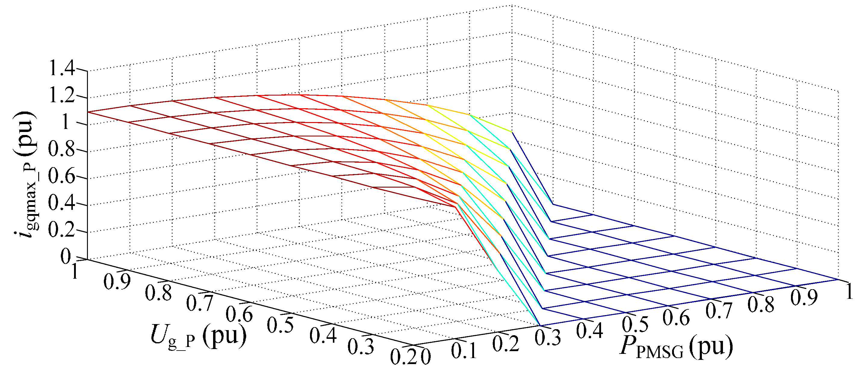
Some nominal parameters of the PMSG-based sub-wind farm under study are given in Table A2 in Appendix A. Set the per-unit allowable maximum current amplitude of the GSC Igmax_P = 1.1 pu. The reactive current limit of the GSC in the PMSG system with different terminal voltage amplitudes (Ug_P) and active power outputs (PPMSG) is shown in Figure 3. As it can be seen from Figure 3, for the constant active power output, the reactive current limit of the GSC in the PMSG system decreases when the voltage amplitude drops. In addition, the reactive current limit of the GSC in the PMSG system also decreases when the output active power increases with a constant voltage at the terminal of the PMSG-based sub-wind farm.
3.3. Reactive Current Limit of the PMSG-Based Sub-wind Farm
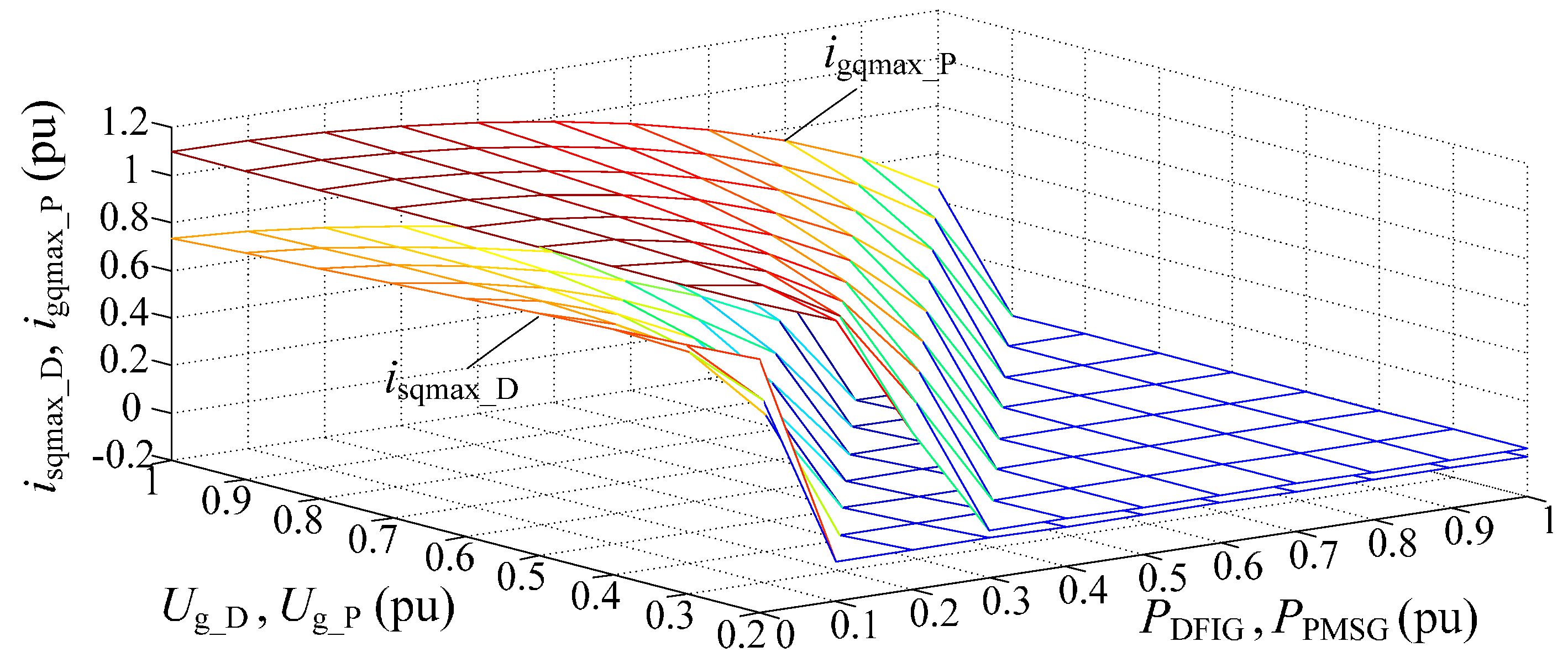
Based on the discussions given in Section 3.1 and Section 3.2, the reactive current limits of the DFIG stator and the GSC in the PMSG system under different terminal voltages and active power outputs of the corresponding sub-wind farms are represented in Figure 4.
From Figure 4, two key conclusions can be obtained:
- For the same active power output, the reactive current limit of the GSC in the PMSG system (igqmax_P) is larger than that of the DFIG stator (isqmax_D), because of a much larger capacity of the GSC in the PMSG system than that of the RSC in the DFIG system. Especially, if the DFIG-based sub-wind farm operates under a sub-synchronous condition, the active power output from the DFIG stator (Ps_D) is more than the total active power output (PDFIG) delivered from the DFIG system. In this case, igqmax_P is much larger than isqmax_D. As a result, during symmetrical grid faults, more reactive current can be supplied by the PMSG-based sub-wind farm than by the DFIG-based sub-wind farm under the same wind speed condition.
- Under the same terminal voltage, the reactive current limits of both the DFIG stator and the GSC in the PMSG system increase when the corresponding active power outputs are reduced. Taking into account of random wind speeds and wide wind turbine geographical distribution, the wind turbines in the hybrid wind farm may be under different power generation conditions. Consequently, much more reactive power support can be supplied by controlling the wind turbines under low power generation conditions. In this way, the operation performance of the hybrid wind farm and the power system to which the wind farm is connected can be further improved during symmetrical grid faults.
4. Coordinated LVRT Control Strategy for the Hybrid Wind Farm under Symmetrical Grid Faults
In order to improve the stability and reliability of grid-connected wind farms, strict LVRT requirements have been implemented worldwide. For instance, the “Technical rule for connecting wind farm to power system” issued in China (GB/T 19963-2011) [26] requires that appropriate reactive currents IQ need to be provided by grid-connected wind farms under symmetrical grid faults; and the per-unit value of IQ must conform to:
where UT and IN are the per-unit values of terminal voltage of a grid-connected wind farm and the rated current of the wind farm, respectively.
It is indicated in Equation (11) that the required minimum reactive current injected by a wind farm under symmetrical grid faults should be 1.5(0.9 − UT)IN, and more reactive current can further help maintain voltage level during transients. However, as discussed in Section 3, a wind power generation system may not be able to supply the required minimum reactive current under some conditions such as the wind farm working under high power generation condition or the terminal voltage of the wind farm being at a lower value region. It is beneficial to find the operation conditions in which the wind farm can provide the required reactive current, which can be used to devise control methods in symmetrical grid fault situations. Those operation conditions are defined as the feasible region of a wind farm.
According to Equations (7), (10) and (11), to meet the LVRT requirements, the corresponding reactive current limits of the DFIG stator and the GSC in the PMSG system need to be:
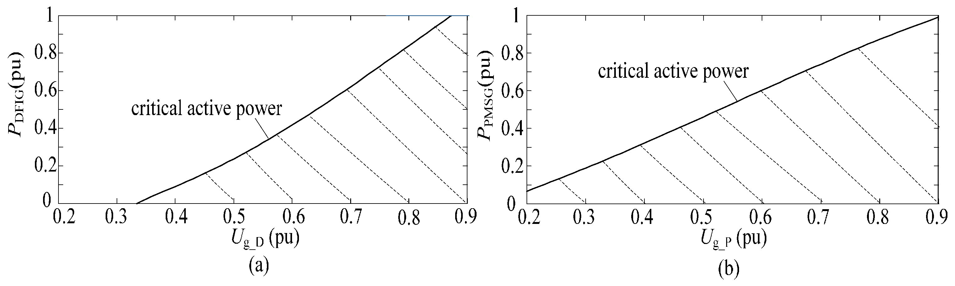
Based on the parameters in Table A3 and Table A4 in Appendix A, the feasible regions of the DFIG-and the PMSG-based sub-wind farms can be derived as:
Figure 5 presents the feasible regions of the DFIG- and PMSG-based sub-wind farms under symmetrical grid faults. When the DFIG- or PMSG-based sub-wind farm operates within its feasible region as the shaded area in Figure 5, the active power output is less than the corresponding critical active power with the certain terminal voltage. This indicates that the reactive current limit of the sub-wind farm is larger than the required minimum value of the LVRT requirement. In other words, under this scenario, the sub-wind farm is capable of providing the required reactive current, while the active power output of the sub-wind farm can still be the same as that under normal condition. On the contrary, when the active power output of the DFIG- or the PMSG-based sub-wind farm is more than its corresponding critical active power during a symmetrical grid fault, the wind turbines will stray from their feasible regions. In this case, the reactive current capacity of the wind system does not meet the LVRT requirement. To deal with this problem, the sub-wind farm has to be controlled to reduce the active power output and to supply the required minimum reactive current to support the grid voltage.
Based on the analysis above, a coordinated LVRT control strategy for the hybrid wind farm with DFIG- and PMSG-based wind turbines is proposed in this paper. Without any additional communication hardware devices, the DFIG- and PMSG-based wind turbines are individually controlled to deliver the respective maximum reactive currents to the power grid. Meanwhile, the variation of the corresponding active power outputs of the two sub-wind farms can be reduced during the symmetrical faults. The current allocation principles of the RSC in the DFIG system and the GSC in the PMSG system are shown in Figure 6.
In the first period after a grid fault occurs, due to the significant voltage sag, the transient component will be appeared in the stator flux, which can cause the over voltage and over current of the rotor circuit. When the amplitude of the over current exceeds the protecting threshold, the active crowbar is triggered to short the rotor circuit of the DFIG, which can accelerate the decay of transient stator flux to avoid over current of the RSC. When the DFIG stator transient flux is almost eliminated, the machine enters the stable short circuit stage and the crowbar is tripped off. The RSC in the DFIG then recovers back to the normal control to provide the transient support to the power grid.
During the low voltage-sustaining period, the voltages at both terminals of DFIG-and PMSG-based sub-wind farms (Ug_D and Ug_P) and the active power outputs (PDFIG and PPMSG) are measured in real time at the corresponding local sites. Then, the measured values of Ug_D, Ug_P, PDFIG, and PPMSG are utilized to judge whether the DFIG- or PMSG-based sub-wind farm is under the corresponding feasible region, as described in Equation (12) and Figure 5. According to the actual situation, one of the following two strategies is applied to control the hybrid wind farm:
- The DFIG- or the PMSG-based sub-wind farm is under its corresponding feasible region. In this case, the reference value of the active current need to be set as that under normal condition, for ensuring the constant active power output before and after the grid faults. In the meantime, the reference value of the reactive current is set as the limit value as given in Equations (7) or (10) to supply the maximum reactive power to the power grid.
- The DFIG- or PMSG-based sub-wind farm is out of its corresponding feasible region. Under this scenario, the reference value of the reactive current is firstly set as the required minimum reactive current of LVRT requirements to meet the grid-connected wind farm code. Considering the allowable maximum current of the DFIG stator or the GSC in the PMSG system, more room can be given to the active current to decrease the curtailment of the active power output of the whole wind farm before and after grid faults.
It is worth stating that the PMSG-based sub-wind farm can immediately employ the low voltage-sustaining strategy when the grid fault occurs, without the operation (crowbar kicked in and tripped off) during the initial period of grid fault like DFIG-based sub-wind farm, owing to the full-scale back-to-back converter configuration.
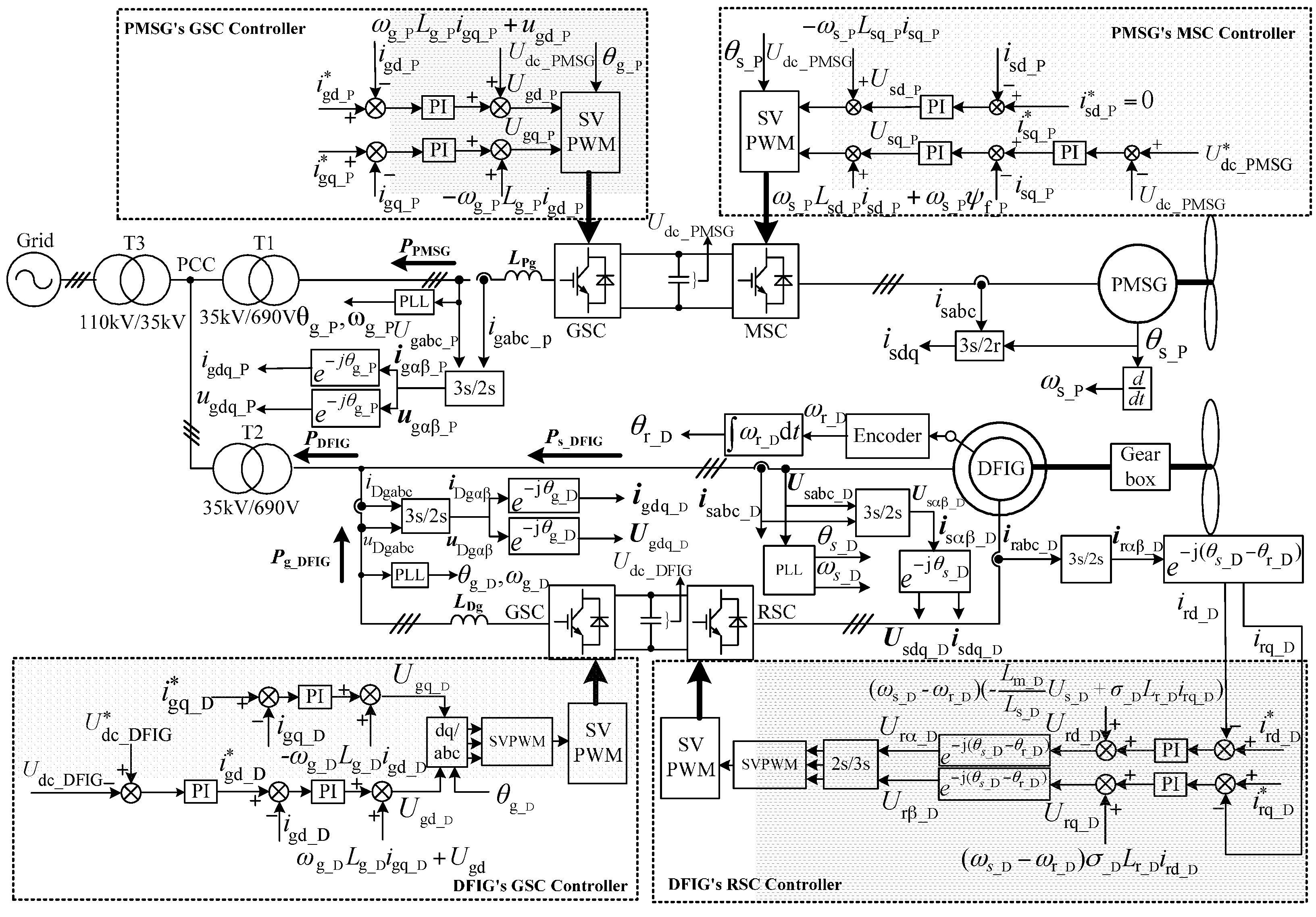
Figure 7 shows the schematic diagram of the proposed coordinated control scheme for the hybrid wind farms under symmetrical fault. The control targets of the GSC in the DFIG and MSC in the PMSG system are still to remain DC-link voltage stable. Moreover, the control targets of the RSC in the DFIG and the GSC in the PMSG system are to achieve the decoupling control of active power and reactive power. By adopting the proposed current allocating principle, the active and reactive current reference values in the DFIG- and the PMSG-based sub-wind farms can be set independently. According to the current reference values, the converters in the wind farm are regulated via appropriate controllers such as PI controllers, and then the operation performance of the hybrid wind farm can be significantly improved during grid faults. On one hand, the maximum reactive current can be supplied by the wind farm, which helps the recovery of the grid voltage. On the other hand, the curtailment of the active power output of the hybrid wind farm can be reduced, which improves the stability of the grid-connected wind farm and provides the transient active power support to the power grid.
5. Simulation Studies
In order to verify the effectiveness of the proposed LVRT control scheme under symmetrical grid faults, simulations on a hybrid wind farm, as shown in Figure 1, have been conducted by using MATLAB/Simulink. The simulation models of the DFIG and PMSG are based on the motor convention. Details of the studied system are given in Appendix A.
During the simulation, the voltage at point A drops to 50% of the rated voltage (0.5 pu). For comparison, the simulation on a 60 MW DFIG-based wind farm is also conducted, which just provides the required minimum reactive current as Equation (11) for the power grid under symmetrical grid faults.
Figure 8a presents the LVRT performance of the 60 MW DFIG-based wind farm, in which half of the DFIGs output 0.2 pu active power (in the low wind speed region), and the others supply 0.8 pu active power (in the high wind speed region) before the symmetrical grid fault occurs. During the first period of the grid fault (2~2.1 s), the active crowbars in DFIG systems are triggered, and the extra reactive current is absorbed from the power grid for excitation of DFIG, which leads to the voltage at PCC (Ug) further dropping to 0.48 from 0.5 pu. At the same time, there is an elevation in DC link voltages (Udc_D1 and Udc_D2) and the rotor rotational speed (ω_D1 and ω_D2) begins to increase. During the second period of the symmetrical grid fault (2.1~2.625 s), with the stable DC link voltage, both of the two DFIG-based sub-wind farms inject 0.421 pu reactive current (isq_D1 and isq_D2) and 0.263 pu reactive power (QDFIG1 and QDFIG2) to the power grid. Correspondingly the voltage at PCC is elevated to 0.625 from 0.48 pu. However, the stator current of the DFIG system with low wind speed (isd_D1) is much less than the allowable maximum current value, which indicates that more reactive current could be output for further supporting the grid voltage. In addition, the rotor rotational speed (ω_D1 and ω_D2) gradually return to the stable operation state value when the symmetrical fault is cleared.
With the proposed LVRT control strategy, the simulation results of the hybrid wind farm consisting of 30 MW DFIG-based sub-wind farm and 30 MW PMSG-based sub-wind farm under 0.5 pu grid voltage dip depth are presented in Figure 8b–d.
Before the symmetrical grid fault occurs, 0.2 pu active power and 0.8 pu active power are output by the DFIG- and PMSG-based sub-wind farms, respectively, and the corresponding simulation results are shown in Figure 8b. Under this scenario, the DFIG-based sub-farm is within its feasible region. Consequently, the output reactive current of the DFIG system (isq_D) increases to 0.652 pu according to the corresponding reactive current limit, meanwhile, the output reactive power (QDFIG) increases to 0.422 pu and the active power (PDFIG) is maintained at 0.2 pu. On the contrary, according to Figure 5b, the PMSG-based sub-wind farm is out of its feasible region because of the active current at large value region. As a result, the PMSG system only supplies 0.374 pu reactive current (igq_P) and 0.244 pu reactive power (QPMSG) to preliminarily meet the requirements in the grid code, while the output active power (PPMSG) decreases to 0.461 pu. Under such condition, the voltage at PCC is elevated to 0.648 from 0.5 pu, and the total reactive current of the hybrid wind farm increases to 1.026 from 0.842 pu, which is 19.12% larger than that of the 60 MW DFIG-based wind farm in scenario (a). Similarly, the total output reactive power increases to 0.661 from 0.526 pu, which is 26.72% more than that of the 60 MW DFIG-based wind farm. Meanwhile, the total output active power also increases to 0.89 from 0.731 pu, which is 21.92% larger than that of the 60 MW DFIG-based wind farm in scenario (a). The analysis indicates that the hybrid wind farm with DFIG and PMSG achieves a superior operation performance over the wind farm only containing DFIG.
Figure 8c presents the simulation results of the hybrid wind farm, in which the DFIG-based sub- wind farm outputs 0.8 pu active power and the PMSG-based sub-wind farm outputs 0.2 pu active power before the symmetrical grid fault occurs. Compared to the DFIG system with the same active power output, the PMSG system has a larger reactive current limit, as shown in Figure 4. Therefore, under this condition, the total reactive current of the hybrid wind farm increases to 1.411 from 0.842 pu, which is 67.58% more than that of the 60 MW DFIG-based wind farm in scenario (a). Similarly, the output reactive power increases to 0.983 pu, and it is 86.88% more than that of the 60 MW DFIG-based wind farm in scenario (a). As a result, the voltage at PCC is elevated to 0.693 from 0. 5 pu.
When both of the DFIG- and PMSG-based sub-wind farms output 0.2 pu active power, the two sub-wind farms are both within their corresponding feasible regions. As a consequence, the whole system can provide more reactive to support the power grid, and avoid the generator over-speed issues. The corresponding simulation results are shown in Figure 8d. As can be seen from Figure 8d, the total output reactive current and reactive power increase to 1.743 from 0.842 pu and 1.227 from 0.526 pu, respectively. As a result, the voltage at PCC is significantly elevated to 0.702 from 0.5 pu, which indicates that the transient grid voltage level and the LVRT capability of the hybrid wind farm are both significantly improved.
When the voltage at point A severely dips to 0.2 pu, the LVRT performance of the hybrid wind farm with the proposed control strategy is given in Figure 9.
Figure 9a shows the simulation results, in which the DFIG- and PMSG-based sub-wind farms output 0.2 pu active power and 0.8 pu active power respectively, before the symmetrical grid fault occurs. Under this condition, both of the two sub-wind farms are out of their corresponding feasible region. As a consequence, they are controlled to reduce the output active power and preferentially supply the required minimum reactive current to meet the grid code, which elevates the voltage at PCC to 0.382 from 0.2 pu.
Before the severe symmetrical grid fault occurs, the DFIG- and PMSG-based sub-wind farm are controlled to output 0.8 pu active power and 0.2 pu active power, respectively. Figure 9b shows the simulation results of the hybrid wind farm. Compared with Figure 9a, because the PMSG system can supply more reactive current, the total reactive current and reactive power output by the hybrid wind farm are much more under this operation condition. Consequently, the voltage at PCC is obviously elevated to 0.408 from 0.2 pu.
With different grid voltage dip depths, the values of the voltage at the PCC under different operation conditions are listed in Table 1. It can be seen that, compared with the 60 MW DFIG-based wind farm with traditional control strategy, the LVRT performance of the hybrid wind farm with the proposed control strategy can be further improved. On the one hand, the transient grid voltage level can be effectively enhanced, because of more reactive current and reactive power provided by the hybrid wind farm. On the other hand, the proposed LVRT control strategy can help the hybrid wind farm to output the active power as much as possible under symmetrical grid faults, which helps avoid generator over-speed issues and provides transient active power support to the power grid.
6. Experimental Results
The experimental hybrid generators-based wind energy conversion system consisting of a DFIG and a PMSG, which are both based on the motor convention, has been built in the lab for verifying the effectiveness of the proposed coordinated LVRT control scheme. The schematic diagram and the setup of the experimental system are shown in Figure 10 and Figure 11, respectively, and the detailed parameters of the test system are given in Appendix B.
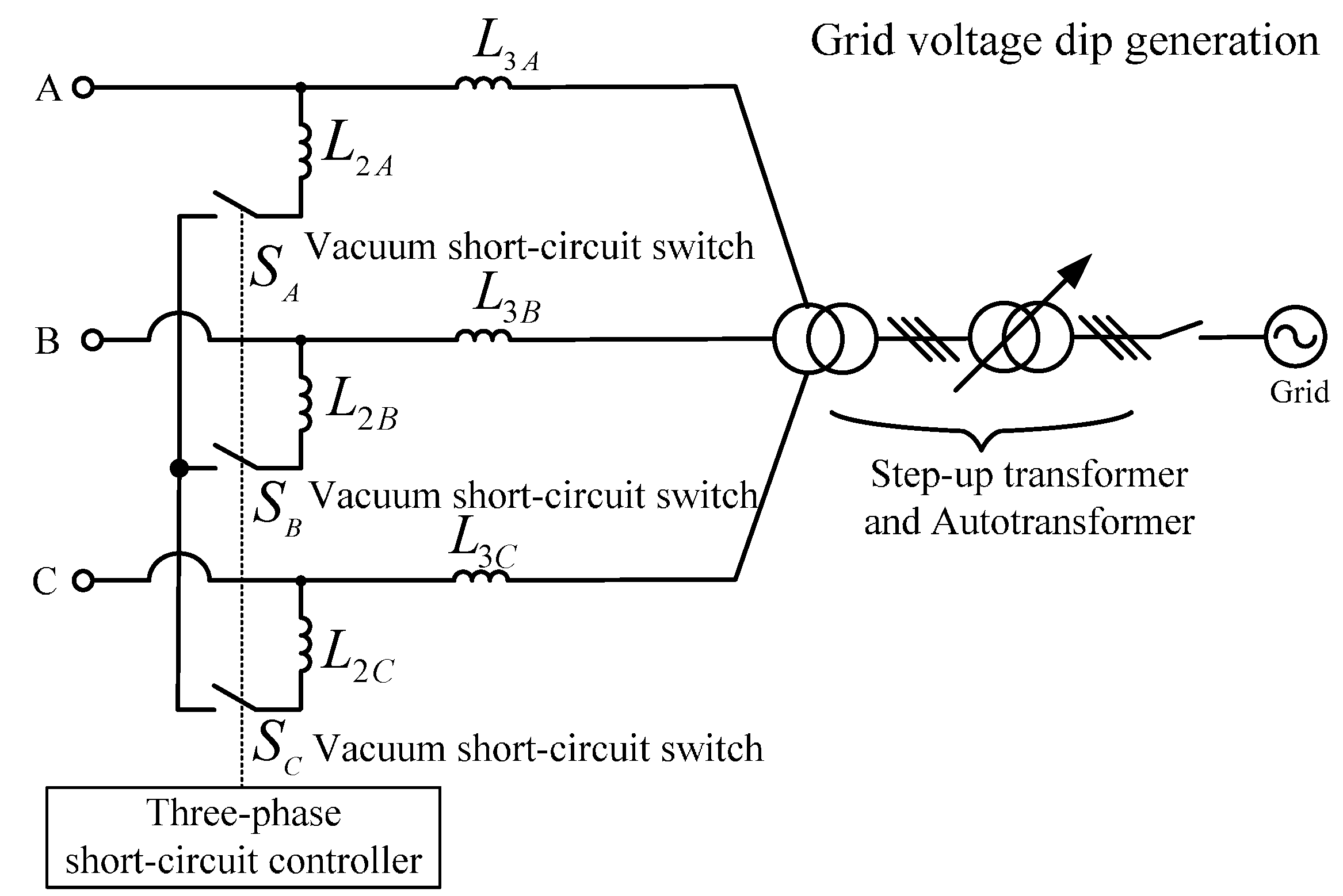
As shown in Figure 10 and Figure 11, the DFIG and the PMSG are driven respectively by a DC motor and an induction motor, which are both operated by using the constant speed control. Therefore, the rotor speed of the DFIG and PMSG basically will not change during the faults. Furthermore, the grid voltage sag is generated using three air core reactors (L2A/L2B/L2C) and three-phase short-circuit switches, as shown in Figure 12. Initially, the three-phase vacuum short-circuit switches (SA/SB/SC) are disconnected, and the experimental hybrid wind power generation test bench is directly connected to the power grid through the series inductor. At the 2.0 s, the three-phase vacuum short-circuit switches are closed and the simulated symmetrical fault occurs, the grid voltage at PCC dips to 0.45 pu. At the 3.1 s, the vacuum short-circuit switches are disconnected and the symmetrical fault is cleared, the grid voltage recovers back to 1.0 pu. For the DFIG system, the crowbar is triggered at 2 s and disabled at 2.2 s when the LVRT control strategy is applied. At 3.1 s, the crowbar is triggered again and stays operating until 3.3 s. Different from the DFIG system, the LVRT control strategy is employed at 2 s and disabled at 3.1 s in the PMSG system.
In order to highlight the advantages of the proposed coordinated LVRT control strategy, the experiment for the hybrid wind power system with the traditional LVRT control strategy which just provides the required minimum reactive current is also conducted for comparison. Before the symmetrical grid fault occurs, the active power outputs of the PMSG and the DFIG are both set at 0.2 pu for simulating the low wind speed operation condition. The experimental results are shown in Figure 13.
As seen from Figure 13c,f–h, with the conventional LVRT control strategy, the reactive currents provided by the PMSG and the DFIG (igq_P and isq_D) are both 0.675 pu, which is equal to the required minimum value as Equation (11). Meanwhile, the reactive power outputs from the DFIG and the PMSG (QDFIG and QPMSG) are both 0.34 pu. In addition, because both the DFIG and the PMSG operate within the corresponding feasible regions under such condition, the active currents of the two systems (igd_P and isd_D) are at low value regions, even during the grid fault. Hence, the active power outputs (PDFIG and PPMSG) can still be 0.2 pu. The voltage at PCC (Ug) is elevated from 0.45 to 0.5 pu as shown in Figure 13a. However, the currents of both the GSC in the PMSG and the DFIG stator are much less than the respective allowable maximum values, as shown in Figure 13b,e. This indicates that more reactive current can be supplied to the power grid for further elevating the voltage at PCC in such symmetrical grid fault situation.
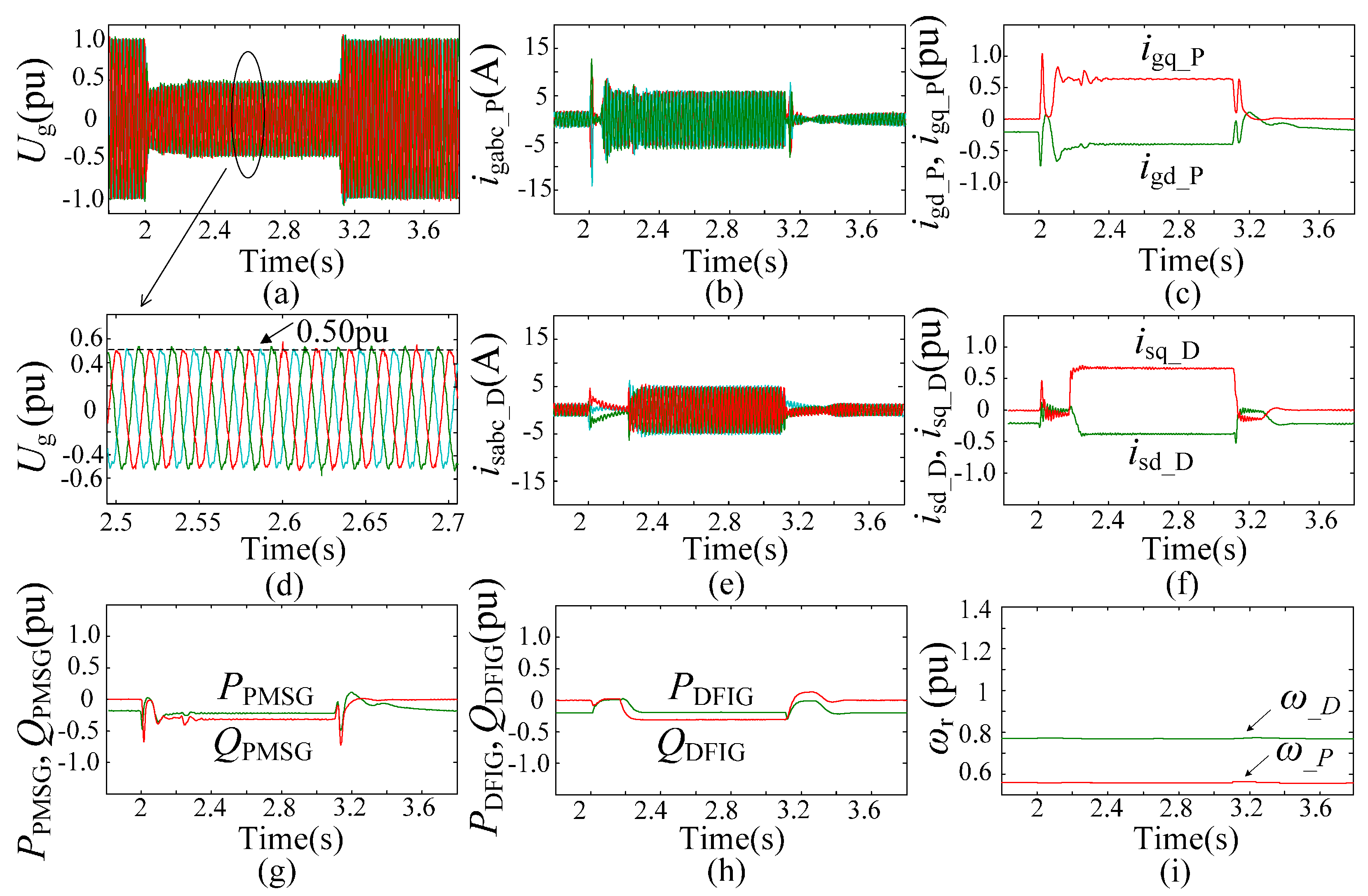
Figure 14 shows the experimental results with the proposed coordinated LVRT control strategy when 0.2 pu active power is being delivered from both the DFIG and the PMSG systems. Under this condition, the DFIG and the PMSG are both within their corresponding feasible regions. Hence, the currents of the GSC in the PMSG system and the DFIG stator (igabc_P and isabc_D) can be made full use of to improve the operation performance of the hybrid generation system during grid faults, as shown in Figure 14b,e. As shown in Figure 14c,f–h, 1.07 and 0.97 pu reactive currents (igq_P and isq_D) which are equal to the corresponding upper limit values can be injected by the PMSG and the DFIG systems, respectively. As a result, the maximum reactive power (QPMSG and QDFIG) can be generated from the hybrid generation system. Meanwhile, the active power outputs of the two systems (PPMSG and PDFIG) are still 0.2 pu without changing before and after grid faults. Compared with Figure 13a, the voltage at PCC (Ug) can be significantly elevated from 0.45 to 0.544 pu with the proposed control strategy, as seen from Figure 14a.
To further verify the effectiveness of the proposed coordinated LVRT control strategy, the experiment is conducted with 0.2 pu active power output from the DFIG and 0.8 pu active power output from the PMSG, which simulates the high wind speed operation condition, as shown in Figure 15. During the grid fault, the DFIG system is within its feasible region. Consequently, 0.95 pu reactive current (isq_D) and 0.49 pu reactive power (QDFIG) can be provided by the DFIG system according to the reactive current limit. Meanwhile, the active power output from the DFIG system (PDFIG) can be controlled constant, as shown in Figure 15e,f,h. On the contrary, the PMSG system is out of its feasible region, thus, the injected reactive current (igq_P) is still 0.675 pu, and the reactive power output (QPMSG) is only 0.35 pu. As the active current of the PMSG system is limited according to the allowable maximum current of the GSC, the active power output from the PMSG (PPMSG) is less than that under normal operation condition, as shown in Figure 15b,c,g. Compared with Figure 14a, the voltage at PCC (Ug) is increased from 0.45 to 0.512 pu, owing to the less reactive current delivered from the PMSG system, as seen from Figure 15a.
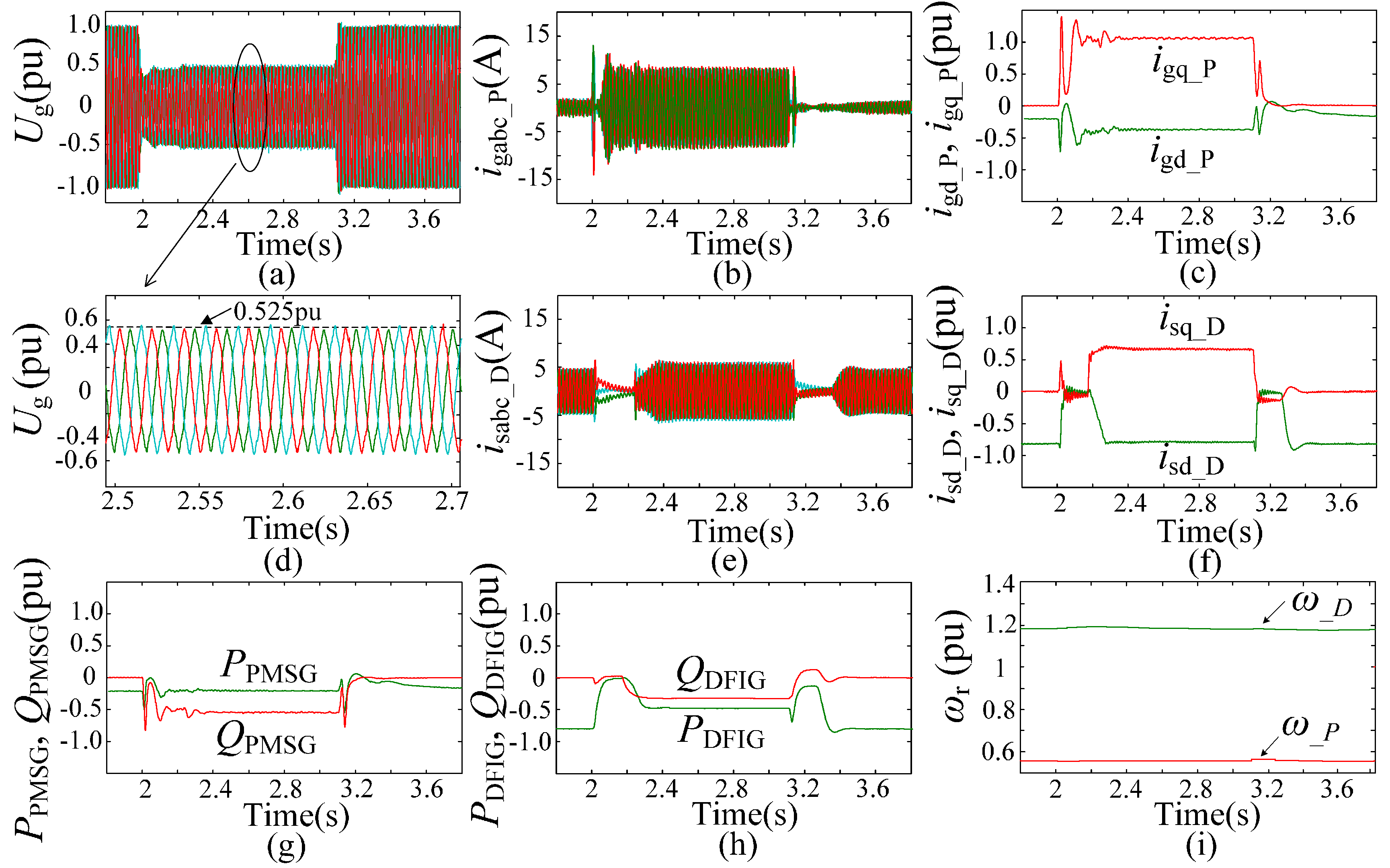
Similarly, Figure 16 shows the experimental results with 0.2 pu active power output from the PMSG and 0.8 pu active power output from the DFIG. In this situation, the DFIG is out of its feasible region while the PMSG is in. Thus, as seen from Figure 16c,f–h, the active power output from the PMSG (PPMSG) is still 0.2 pu, but the value (PDFIG) is less than 0.8 pu for DFIG system during grid fault. In addition, 1.05 pu reactive current (igq_P) and 0.55 pu reactive power (QPMSG) can be generated by the PMSG system. However, only 0.675 pu reactive current (isq_D) and 0.36 pu reactive power (QDFIG) are injected to the grid by the DFIG system. Compared with Figure 15a, the voltage at PCC (Ug) is increased from 0.45 to 0.525 pu, owing to the reactive current capability of the PMSG system when it operates at a low active power value region, as shown in Figure 16a.
7. Conclusions
This paper focuses on a coordinated LVRT control scheme for a hybrid wind farm with a DFIG-based sub-wind farm and a PMSG-based sub-wind farm under symmetrical grid faults. The reactive current upper limits of the DFIG stator and the GSC in the PMSG system have been derived under symmetrical fault conditions, respectively, which are both determined by the terminal voltage dip depths and the active power output levels of the corresponding sub-wind farms. On this basis, according to the grid code, the feasible regions of the DFIG- and the PMSG-based sub-wind farms have been established. Furthermore, an improved reactive current allocation method and a coordinated LVRT control strategy for the hybrid wind farm have been proposed to enhance the operation performance of the wind power generation system and the power grid voltage during the symmetrical fault. The theoretical analysis and the proposed coordinated LVRT control strategies have been validated by the simulation studies and the laboratory-scale experimental tests. Both the simulation and actual experimental results show that the control strategies proposed in this paper can significantly improve the transient performance of the hybrid wind farm during symmetrical fault.
Acknowledgments
This work was supported in part by the National Natural Science Foundation of China under Grant 51477016 and the Open Fund of State Key Laboratory of Operation and Control of Renewable Energy & Storage Systems (China Electric Power Research Institute).
Author Contributions
Jun Yao proposed the main idea of the manuscript and supervised the whole research work. Jiawei Li and Xin Zeng built the simulation and wrote the manuscript. Ruikuo Liu and Depeng Xu conceived and performed the experimental work. Caisheng Wang reviewed the work and gave a lot of helpful improvement suggestions during the construction and revision of this paper.
Conflicts of Interest
The authors declare no conflict of interest.
Appendix A
Simulation System Parameters

Table A1.
Parameters of the DFIG-based sub-wind farm.
| Parameters | Values | Parameters | Values |
|---|---|---|---|
| Ratings | 30 MW | Pole pairs | 2 |
| Rated generator voltage | 690 V | Frequency | 50 Hz |
| Stator resistance | 0.00488 pu | Stator leakage inductance | 0.1386 pu |
| Rotor resistance | 0.00549 pu | Rotor leakage inductance | 0.1493 pu |
| Magnetizing inductance | 3.9527 pu | Ns/Nr (kt) | 0.45 |
Table A2.
Parameters of the PMSG-based sub-wind farm.
| Parameters | Values | Parameters | Values |
|---|---|---|---|
| Ratings | 30 MW | Pole pairs | 28 |
| Rated generator voltage | 690 V | Frequency | 50 Hz |
| Stator resistance | 0.0126 pu | D- & Q-axis inductance | 1.321 pu |
| Reactor resistance | 0.0126 pu | Reactor inductance | 0.396 pu |
Table A3.
Parameters of the transmission network.
| Parameters | Values | Parameters | Values |
|---|---|---|---|
| Ratings of T1 & T2 | 35 MVA | Frequency | 50 Hz |
| Short circuit impedance of T1 & T2 | 0.0098 + j0.09241 pu | Ratings of T3 | 150 MVA |
| Line Z3 + Z4 | 100 km, 0.105 + j0.383 Ω/km | Line Z1 & Z2 | 5 km, 0.17 + j0.38 Ω/km |
Appendix B
Experimental System Parameters
Table A4.
Parameters of the DFIG system.
| Parameters | Values | Parameters | Values |
|---|---|---|---|
| Ratings | 3 kW | Pole pairs | 2 |
| Rated generator voltage | 380 V | Frequency | 50 Hz |
| Stator resistance | 0.0081 pu | Stator leakage inductance | 0.1358 pu |
| Rotor resistance | 0.1304 pu | Rotor leakage inductance | 0.3466 pu |
| Magnetizing inductance | 6.1744 pu | Ns/Nr (kt) | 0.517 |
| Winding connection | Y/Y | Common dc-link capacitor | 2200 μF |
| Reactor resistance | 0.1 Ω | Reactor inductance | 5 mH |
Table A5.
Parameters of the PMSG system.
| Parameters | Values | Parameters | Values |
|---|---|---|---|
| Ratings | 3 kW | Pole pairs | 2 |
| Rated generator voltage | 380 V | Frequency | 50 Hz |
| Stator resistance | 0.09 pu | Common dc-link capacitor | 2200 μF |
| D-axis inductance | 0.78 pu | Q-axis inductance | 1.07 pu |
| Reactor resistance | 0.1 Ω | Reactor inductance | 5 mH |
References
- Ma, K.; Blaabjerg, F. Modulation methods for neutral-point-clamped wind power converter achieving loss and thermal redistribution under low-voltage ride-through. IEEE Trans. Ind. Electron. 2014, 61, 835–845. [Google Scholar] [CrossRef]
- Muyeen, S.; Takahashi, R.; Murata, T.; Tamura, J. A variable speed wind turbine control strategy to meet wind farm grid code requirements. IEEE Trans. Power Syst. 2010, 25, 331–340. [Google Scholar] [CrossRef]
- Erlich, I.; Bachmann, U. Grid code requirements concerning connection and operation of wind turbines in Germany. In Proceedings of the IEEE Power Engineering Society General Meeting, San Francisco, CA, USA, 12–16 June 2005; pp. 1253–1257. [Google Scholar]
- Tsili, M.; Papathanassiou, S. A review of grid code technical requirements for wind farms. IET Renew. Power Gener. 2009, 3, 308–332. [Google Scholar] [CrossRef]
- ON-Netz, E. Grid Code: High and Extra High Voltage; E-One Netz GmbH: Bayreuth, Germany, 2006. [Google Scholar]
- Geng, H.; Liu, C.; Yang, G. LVRT capability of DFIG-based WECS under asymmetrical grid fault condition. IEEE Trans. Ind. Electron. 2013, 60, 2495–2509. [Google Scholar] [CrossRef]
- Kim, K.-H.; Jeung, Y.-C.; Lee, D.C.; Kim, H.G. LVRT scheme of PMSG wind power systems based on feedback linearization. IEEE Trans. Power Electron. 2012, 27, 2376–2384. [Google Scholar] [CrossRef]
- Li, S.; Haskew, T.A.; Swatloski, T.P.; Gathings, W. Optimal and direct-current vector control of direct-driven PMSG wind turbines. IEEE Trans. Power Electron. 2012, 27, 2325–2337. [Google Scholar] [CrossRef]
- Hu, J.; Wang, S.; Tang, W.; Xiong, X. Full-capacity wind turbine with inertial support by adjusting phase-locked loop response. IET Renew. Power Gener. 2017, 11, 44–53. [Google Scholar] [CrossRef]
- Foster, S.; Xu, L.; Fox, B. Coordinated reactive power control for facilitating fault ride through of doubly fed induction generator- and fixed speed induction generator-based wind farms. IET Renew. Power Gener. 2010, 4, 128–138. [Google Scholar] [CrossRef]
- Foster, S.; Xu, L.; Fox, B. Coordinated control and operation of DFIG and FSIG based Wind Farms. In Proceedings of the IEEE Lausanne Powertech, Lausanne, Switzerland, 1–5 July 2007; pp. 522–527. [Google Scholar]
- Leon, A.E.; Mauricio, J.M.; Gomez-Exposito, A.; Solsona, J.A. An improved control strategy for hybrid wind farms. IEEE Trans. Sustain. Energy 2010, 1, 131–141. [Google Scholar] [CrossRef]
- Wang, L.; Truong, D.-T. Stability enhancement of a power system with a PMSG-based and a DFIG-based offshore wind farm using a SVC with an adaptive-network-based fuzzy inference system. IEEE Trans. Ind. Electron. 2013, 60, 2799–2807. [Google Scholar] [CrossRef]
- Wang, L.; Truong, D.-T. Stability improvement of a hybrid DFIG-based and PMSG-based offshore wind Farm fed to a SG-based power system using a STATCOM. Int. J. Smart Grid Clean Energy 2013, 2, 230–236. [Google Scholar] [CrossRef]
- Hu, S.; Lin, X.; Kang, Y.; Zou, X. An improved low-voltage ride-through control strategy of doubly fed induction generator during grid faults. IEEE Trans. Power Electron. 2011, 26, 3653–3665. [Google Scholar] [CrossRef]
- Xiang, D.; Ran, L.; Tavner, P.J.; Yang, S. Control of a doubly fed induction generator in a wind turbine during grid fault ride-through. IEEE Trans. Energy Convers. 2006, 21, 652–662. [Google Scholar] [CrossRef]
- Lopez, J.; Sanchis, P.; Roboam, X.; Marroyo, L. Dynamic behavior of the doubly fed induction generator during three-phase voltage dips. IEEE Trans. Energy Convers. 2007, 22, 709–717. [Google Scholar] [CrossRef]
- Zhang, S.; Tseng, K.T.; Vilathgamuwa, M.D.; Nguyen, T.D.; Wang, X. Design of a robust grid interface system for PMSG-based wind turbine generators. IEEE Trans. Ind. Electron. 2011, 58, 316–328. [Google Scholar] [CrossRef]
- Polinder, H.; van der Pijl, F.F.A.; de Vilder, G.-J.; Tavner, P.J. Comparison of direct-drive and geared generator concepts for wind turbines. IEEE Trans. Energy Convers. 2006, 21, 725–733. [Google Scholar] [CrossRef]
- Mirecki, A.; Roboam, X.; Richaredau, F. Architecture complexity and energy efficiency of small wind turbines. IEEE Trans. Ind. Electron. 2007, 54, 660–670. [Google Scholar] [CrossRef]
- Ge, J.; Du, M.; Zhang, C. A study on correlation of wind farms output in the large-scale wind power base. In Proceedings of the IEEE International Conference on Electric Utility Deregulation and Restructuring and Power Technologies, Shandong, China, 6–9 July 2011; pp. 1316–1319. [Google Scholar]
- Hussein, D.-N.; Matar, M.; Iravani, R. A type-4 wind power plant equivalent model for the analysis of electromagnetic transients in power systems. IEEE Trans. Power Syst. 2013, 28, 3096–3104. [Google Scholar] [CrossRef]
- Fernandez, L.-M.; Garcia, C.A.; Saebz, J.-R. Equivalent models of wind farms by using aggregated wind turbines and equivalent winds. Energy Convers. Manag. 2009, 5, 691–704. [Google Scholar] [CrossRef]
- Zheng, Z.; Yang, G.; Geng, H. Coordinated control of a doubly-fed induction generator-based wind farm and a static synchronous compensator for low voltage ride-through grid code compliance during asymmetrical grid faults. Energies 2013, 6, 4660–4681. [Google Scholar] [CrossRef]
- Zou, Y.; Elbuluk, M.E.; Sozer, Y. Stability analysis of maximum power point tracking (MPPT) method in wind power systems. IEEE Trans. Ind. Appl. 2013, 49, 1129–1136. [Google Scholar] [CrossRef]
- Technical Stipulation for Connecting Wind Park to the Grid; Chinese Standard: GB/T 19963-2011; China Electric Power Press: Beijing, China, 2011.
Figure 1.
Configuration of the grid-connected hybrid wind farm under study.
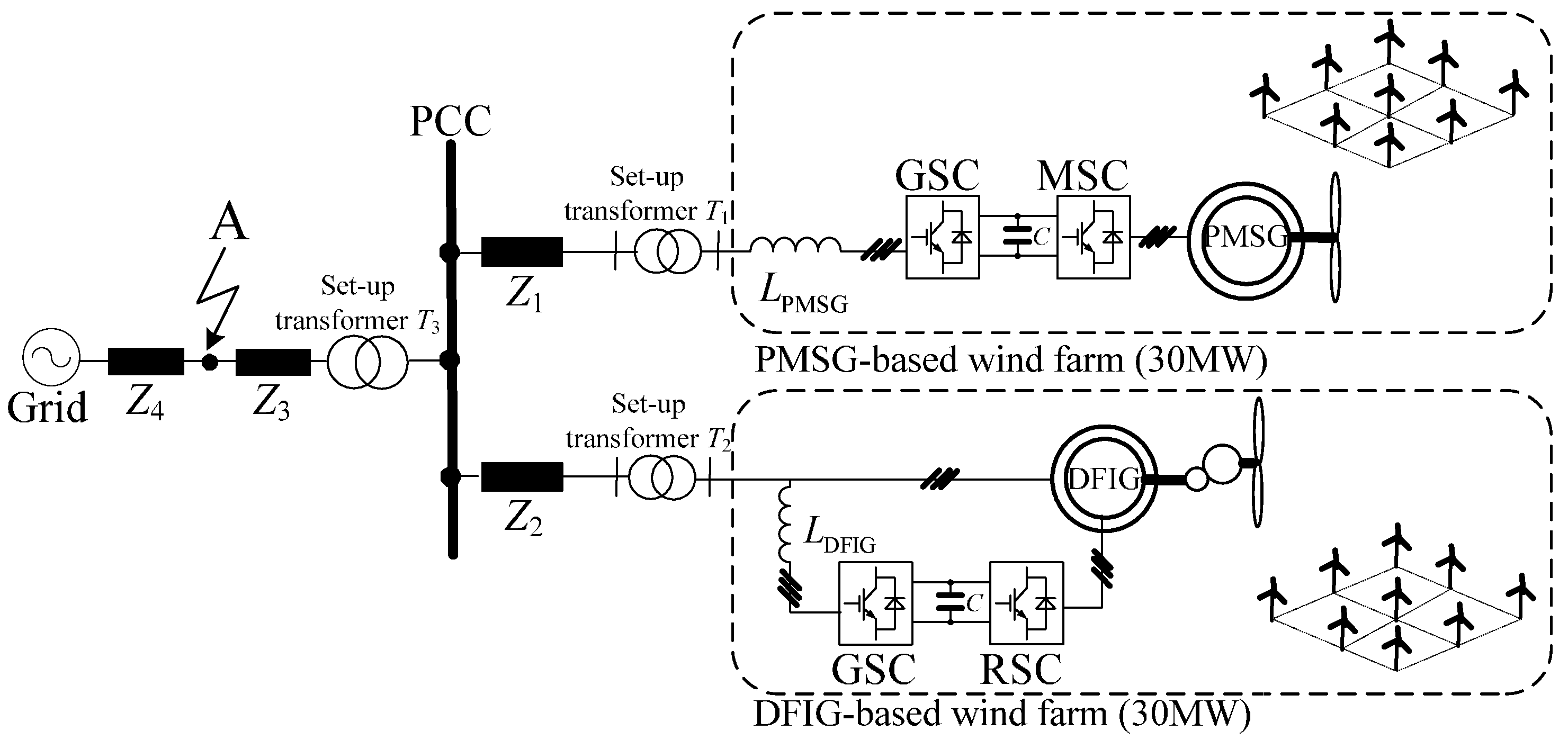
Figure 2.
Reactive current limits of the DFIG-based sub-wind farm with different stator voltage amplitudes and active power outputs.
Figure 2.
Reactive current limits of the DFIG-based sub-wind farm with different stator voltage amplitudes and active power outputs.

Figure 3.
Reactive current limit of the GSC in the PMSG system with different voltage amplitudes and active power outputs.
Figure 3.
Reactive current limit of the GSC in the PMSG system with different voltage amplitudes and active power outputs.

Figure 4.
Reactive current limits of the DFIG stator and the GSC in the PMSG system with different voltage amplitudes and active power outputs.
Figure 4.
Reactive current limits of the DFIG stator and the GSC in the PMSG system with different voltage amplitudes and active power outputs.

Figure 5.
Feasible regions of the hybrid wind farm. (a) Feasible region of the DFIG-based sub-wind farm; (b) Feasible region of the PMSG-based sub-wind farm.
Figure 5.
Feasible regions of the hybrid wind farm. (a) Feasible region of the DFIG-based sub-wind farm; (b) Feasible region of the PMSG-based sub-wind farm.

Figure 6.
Current allocating principles of the RSC in the DFIG-based sub-wind farm and the GSC in the PMSG-based sub-wind farm.
Figure 6.
Current allocating principles of the RSC in the DFIG-based sub-wind farm and the GSC in the PMSG-based sub-wind farm.
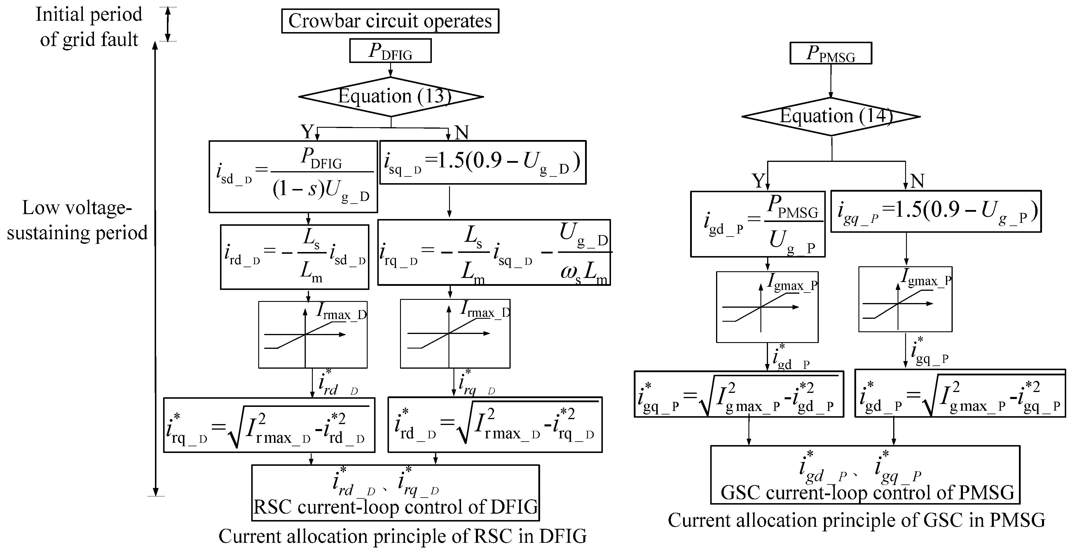
Figure 7.
Schematic diagram of the proposed coordinated control scheme for the hybrid wind farm.

Figure 8.
LVRT simulation results under 50% grid voltage dip depth with different wind farm operation conditions. (a) 0.2 pu active power output from one of the DFIG-based sub-wind farms and 0.8 pu active power output from the another DFIG-based sub-wind farm; (b) 0.2 pu active power output from the DFIG-based sub-wind farm and 0.8 pu active power output from the PMSG-based sub-wind farm; (c) 0.8 pu active power output from the DFIG-based sub-wind farm and 0.2 pu active power output from the PMSG-based sub-wind farm; (d) 0.2 pu active power output from both of the DFIG-and PMSG-based sub-wind farms.
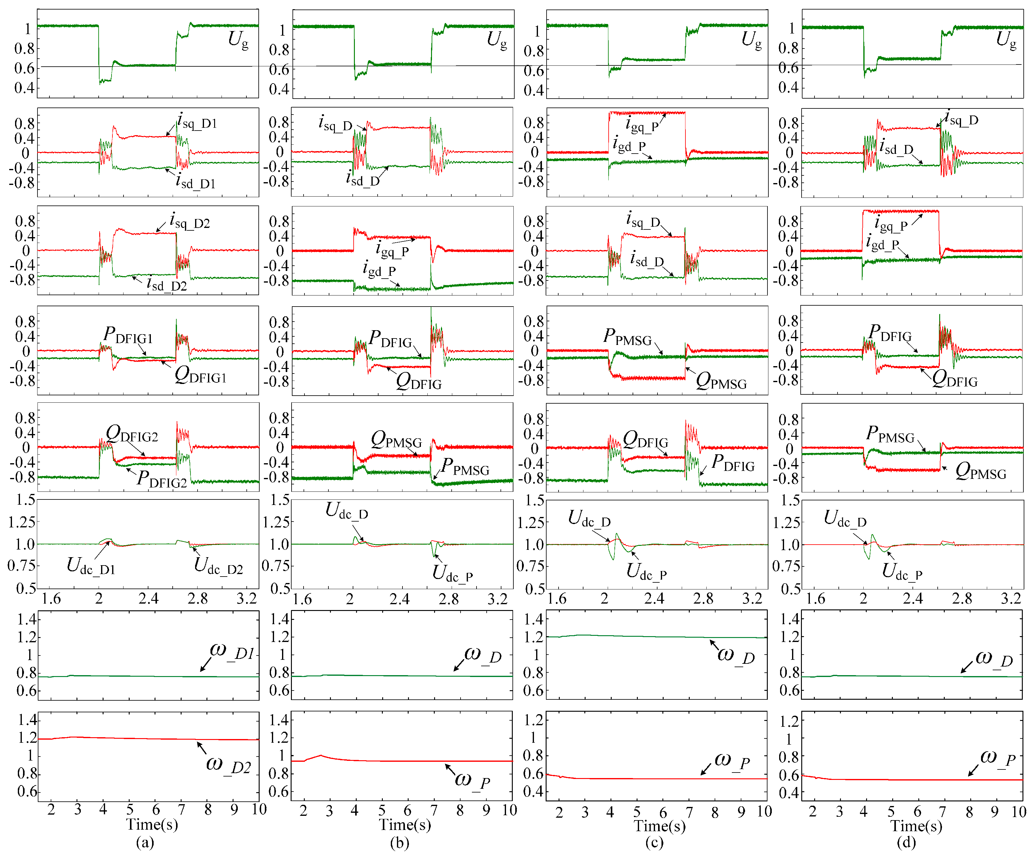
Figure 9.
LVRT simulation results under 20% grid voltage dip depth with different wind farm operation conditions. (a) 0.2 pu active power output from the DFIG-based sub-wind farm and 0.8 pu active power output from the PMSG-based sub-wind farm; (b) 0.8 pu active power output from the DFIG-based sub-wind farm and 0.2 pu active power output from the PMSG-based sub-wind farm.
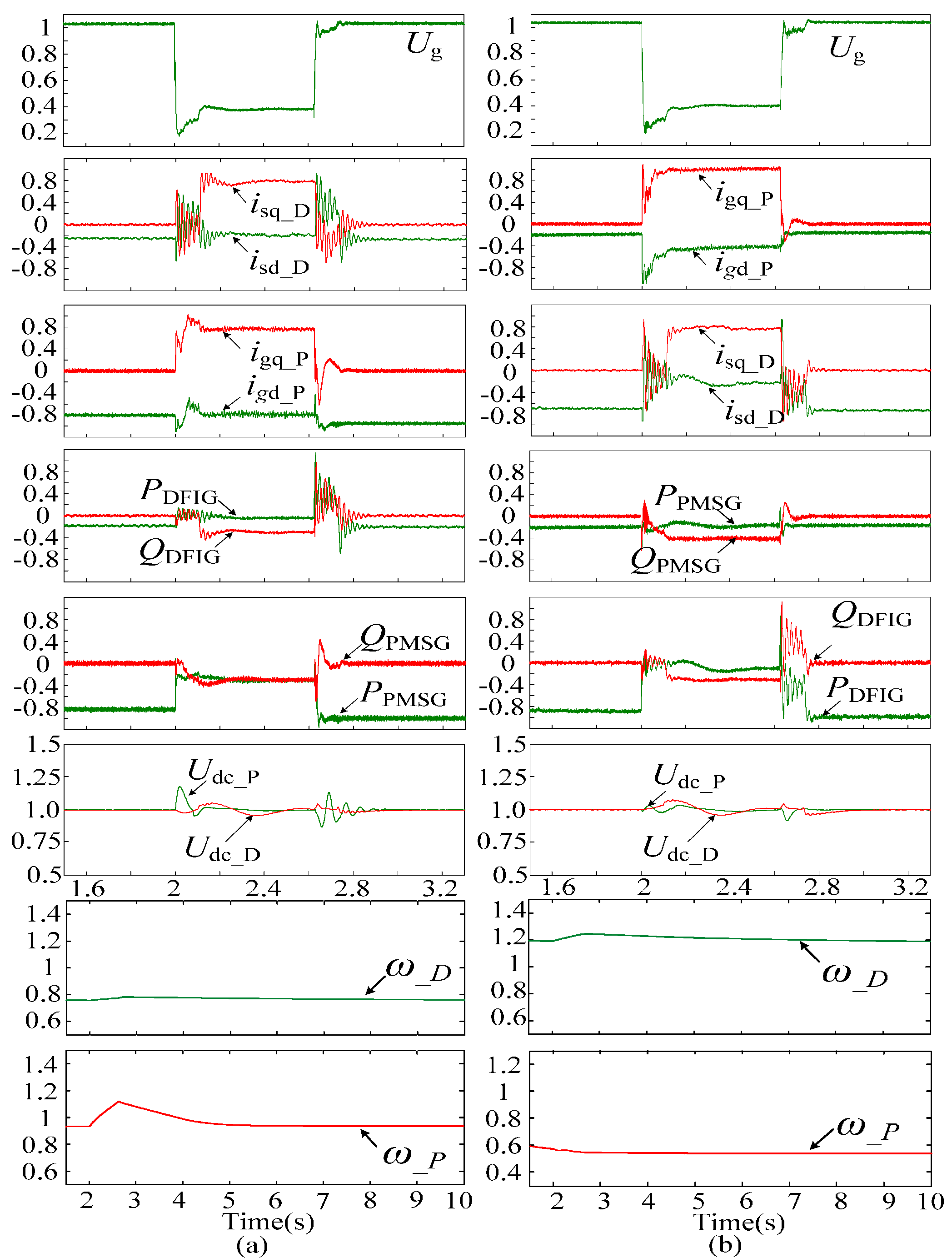
Figure 10.
Schematic diagram of the experimental system.
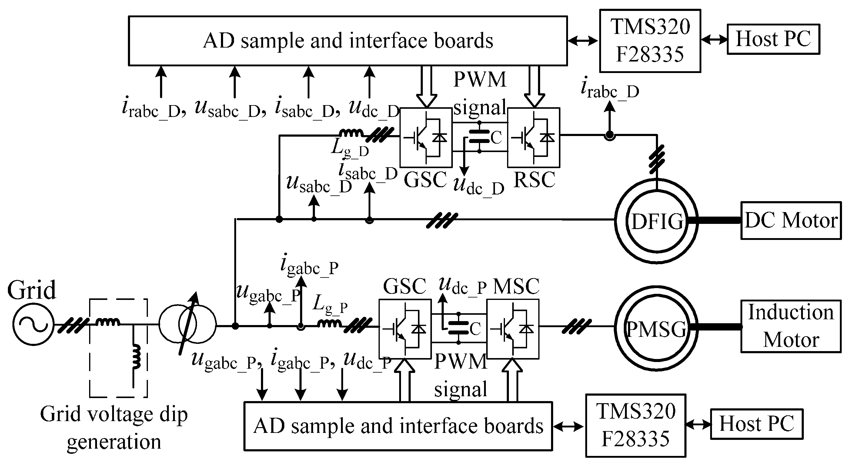
Figure 11.
Experimental setup in the lab.
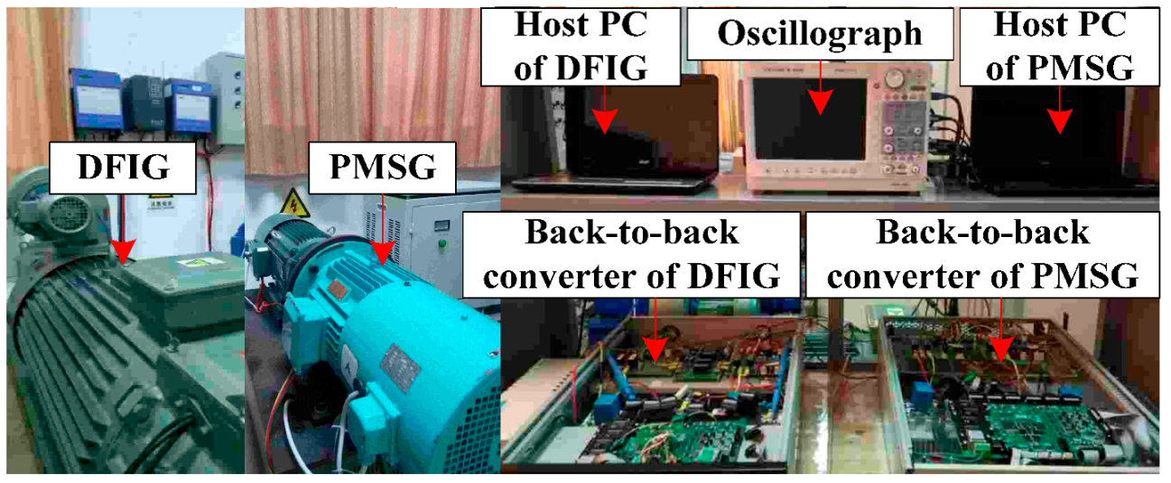
Figure 12.
Circuit schematic of the grid voltage dip generation.

Figure 13.
Experimental results with the traditional LVRT control strategy for the hybrid wind power system with 0.2 pu active outputs from both the DFIG and the PMSG systems. (a) Voltage at PCC; (b) Current of the GSC in the PMSG system; (c) Active and reactive currents of PMSG system; (d) Voltage at PCC; (e) DFIG stator current; (f) Active and reactive currents of DFIG system; (g) Active and reactive power outputs from PMSG system; (h) Active and reactive powers output from DFIG system; (i) Rotor rotational speed of the DFIG and PMSG system.

Figure 14.
Experimental results with the proposed coordinated LVRT control strategy under 0.2 pu active outputs from both the DFIG and the PMSG systems. (a) Voltage at PCC; (b) Current of the GSC in the PMSG system; (c) Active and reactive currents of PMSG system; (d) Voltage at PCC; (e) DFIG stator current; (f) Active and reactive currents of the DFIG system; (g) Active and reactive power outputs from the PMSG system; (h) Active and reactive powers output from the DFIG system; (i) Rotor rotational speed of the DFIG and PMSG systems.
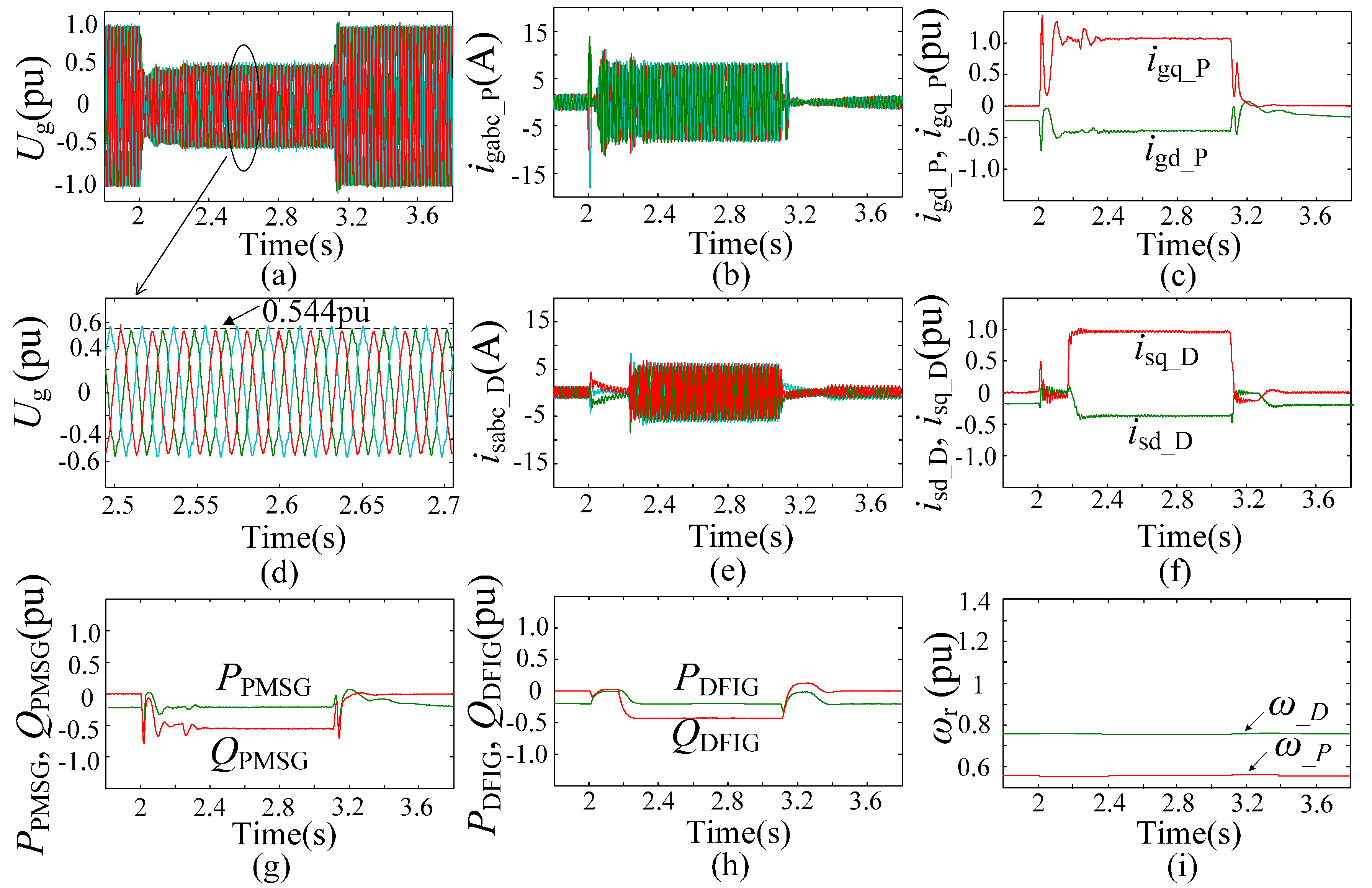
Figure 15.
Experimental results with the proposed LVRT control strategy under 0.8 pu active output from the PMSG system and 0.2 pu active output from the DFIG system. (a) Voltage at PCC; (b) Current of the GSC in the PMSG system; (c) Active and reactive currents of PMSG system; (d) Voltage at PCC; (e) DFIG stator current; (f) Active and reactive currents of the DFIG system; (g) Active and reactive power outputs from the PMSG system; (h) Active and reactive powers output from the DFIG system; (i) Rotor rotational speed of the DFIG and PMSG systems.
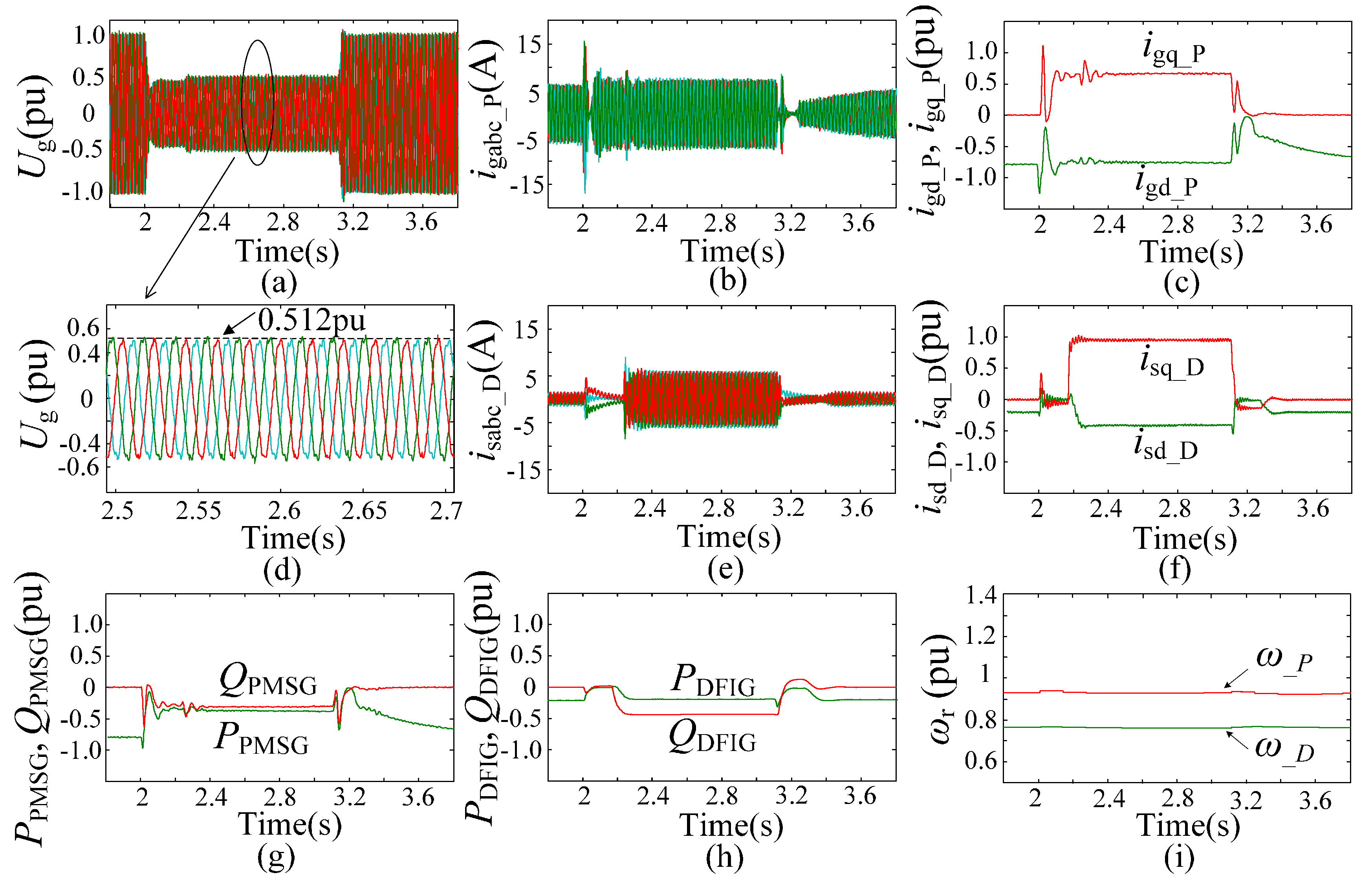
Figure 16.
Experimental results with the proposed LVRT control strategy under 0.2 pu active output from the PMSG system and 0.8 pu active output from the DFIG system. (a) Voltage at PCC; (b) Current of the GSC in the PMSG system; (c) Active and reactive currents of the PMSG system; (d) Voltage at PCC; (e) DFIG stator current; (f) Active and reactive currents of the DFIG system; (g) Active and reactive power outputs from the PMSG system; (h) Active and reactive powers output from the DFIG system; (i) Rotor rotational speed of the DFIG and PMSG systems.

Table 1.
Values of the voltage at PCC under different grid voltage dip depths and operation conditions.
Table 1.
Values of the voltage at PCC under different grid voltage dip depths and operation conditions.
| Ug (pu) | DFIG-Based Wind Farm with Traditional Control Strategy | Hybrid Wind Farm with the Proposed Control Strategy | ||||
|---|---|---|---|---|---|---|
| Voltage at Point A | DFIGs and PMSGs Both with High Wind Speed | DFIGs with Low Wind Speed and PMSGs with High Wind Speed | DFIGs with High Wind Speed and PMSGs with Low Wind Speed | DFIGs and PMSGs Both with Low Wind Speed | ||
| 0.8 pu | 0.859 | 0.902 | 0.963 | 1 | 1 | |
| 0.7 pu | 0.779 | 0.817 | 0.859 | 0.868 | 0.889 | |
| 0.6 pu | 0.698 | 0.704 | 0.731 | 0.773 | 0.787 | |
| 0.5 pu | 0.625 | 0.631 | 0.648 | 0.693 | 0.705 | |
| 0.4 pu | 0.553 | 0.557 | 0.559 | 0.602 | 0.606 | |
| 0.3 pu | 0.458 | 0.462 | 0.463 | 0.495 | 0.497 | |
| 0.2 pu | 0.382 | 0.383 | 0.382 | 0.408 | 0.409 | |
© 2017 by the authors. Licensee MDPI, Basel, Switzerland. This article is an open access article distributed under the terms and conditions of the Creative Commons Attribution (CC BY) license (http://creativecommons.org/licenses/by/4.0/).
Share and Cite
MDPI and ACS Style
Li, J.; Yao, J.; Zeng, X.; Liu, R.; Xu, D.; Wang, C. Coordinated Control Strategy for a Hybrid Wind Farm with DFIG and PMSG under Symmetrical Grid Faults. Energies 2017, 10, 669. https://doi.org/10.3390/en10050669
AMA Style
Li J, Yao J, Zeng X, Liu R, Xu D, Wang C. Coordinated Control Strategy for a Hybrid Wind Farm with DFIG and PMSG under Symmetrical Grid Faults. Energies. 2017; 10(5):669. https://doi.org/10.3390/en10050669
Chicago/Turabian StyleLi, Jiawei, Jun Yao, Xin Zeng, Ruikuo Liu, Depeng Xu, and Caisheng Wang. 2017. "Coordinated Control Strategy for a Hybrid Wind Farm with DFIG and PMSG under Symmetrical Grid Faults" Energies 10, no. 5: 669. https://doi.org/10.3390/en10050669
Note that from the first issue of 2016, this journal uses article numbers instead of page numbers. See further details here.