
Dynamic Charging of Electric Vehicle with Negligible Power Transfer Fluctuation


1
Power Electronics and Renewable Energy Research Laboratory (PEARL), Department of Electrical Engineering, University of Malaya, Kuala Lumpur 50603, Malaysia
2
School of Engineering, Deakin University, Waurn Ponds, Victoria 3216, Australia
*
Author to whom correspondence should be addressed.
Energies 2017, 10(5), 701; https://doi.org/10.3390/en10050701
Submission received: 9 March 2017
/
Revised: 29 April 2017
/
Accepted: 3 May 2017
/
Published: 16 May 2017
(This article belongs to the Special Issue Advances in Electric Vehicles and Plug-in Hybrid Vehicles 2017)
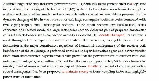
Abstract
:High-efficiency inductive power transfer (IPT) with low misalignment effects is a key issue in the dynamic charging of electric vehicle (EV) systems. In this study, an advanced concept of analysis and design of transmitter and receiver coils with a special coil assembly is proposed for the dynamic charging of EVs. In each transmitter coil, large rectangular section is series connected with two zigzag-shaped small rectangular sections. These small sections are back-to-back series connected and located inside the large rectangular section. An adjacent pair of proposed transmitter coils with back-to-back series connection named extended double D (DD)-shaped transmitter is used throughout this paper. The major contribution in the case of the extended DD transmitter is negligible power transfer fluctuation, regardless of any horizontal misalignment of the receiver coil. Justification of the coil design is performed based on its load independent voltage gain and power transfer fluctuation characteristics. Experimental results prove that the power transfer fluctuation with load independent voltage gain is within ±6%, and the efficiency is approximately 93% under horizontal misalignment of receiver coil with an air gap of 140 mm. Finally, a new coil design set with a special arrangement has been proposed to maintain nearly uniform coupling factor and negligible power transfer fluctuation.
1. Introduction
In recent years, inductive power transfer (IPT) systems have been extensively developed for electric vehicle (EV) charging applications. Most researchers focus on stationary charging of different IPT systems. On the contrary, dynamic charging of EV systems can mitigate the weight and battery size and improve transportation efficiency [1,2,3]. However, the design of transmitter and receiver coils as well as misalignment and load conditions influence the overall performance [4,5,6,7,8,9]. Transmitter coils are generally classified into two categories: long-track designs [10,11,12,13] and segmented-track designs [14,15,16], both of which exhibit the performance issues identified above.
The size assembly of the transmitter coil in segmented-track settings is similar to that of the transmitter in the stationary charging of an EV system in typically being within a size of 1 m [17]. Segmented transmitter coils are arranged as an array to form a tracking lane for the EV; this arrangement is highly convenient to design and build the effective length of powered roadway as each segmented transmitter coil with a certain structure has its own compensation network. These transmitter coils are turned on in accordance with the position of the receiver coil pad; as a result, the transmitter coil can be turned off, thereby resulting in high efficiency and low magnetic leakage flux distribution [18,19] when the receiver coil pad passes by. However, the complexity of the segmented transmitter architecture becomes one of the limitations of this configuration as it needs a huge number of compensation networks and power electronic converters. As a result, this configuration incurs higher cost, unlike a long guided track transmitter. Therefore, several segmented transmitter coils are connected in either series or parallel to share the same power electronic converter and thus minimize the total cost. The power transfer fluctuation that occurs in the receiver coil when it moves is another limitation of this configuration. In general, most transmitters are arranged far away from each other in order to minimize the self-coupling. Consequently, when the receiver is in a position between the two transmitters, the magnetic-field is weak and the receiver side power drops [18]. To overcome the power drop issues, transmitters can be placed closer to each other to increase the power received in the middle position due to the increase in the magnetic field between the transmitters. To date, the issue regarding the power transfer fluctuation phenomenon still exists [14,17]. Self-coupling also occurs with the decrease in the distance between the transmitters. The issues on self-coupling and power transfer fluctuation can be adjusted by the proper design of the transmitter and receiver coils as well as its arrangement. Hence, the design of the charging pad plays an important role in achieving high efficiency.
The flux path height of a circular pad is about one-fourth of its diameter and this causes the poor coupling between the transmitter and receiver pads. A circular pad of large dimension is usually adopted to obtain high power transfer efficiency; however, this design makes the EV charging system impractical. This circular pad is ineffective for dynamic charging of EVs as a null power transfer zone exists when the receiving pad is horizontally misaligned by 38% of the transmitter pad diameter [20]. For a double D-shaped (DD) pad, the flux path height is around half the total length for a pad. For a circular pad of homogeneous size, the DD pad shows a notable improvement in the coupling. The charging zone for a DD pad is nearly two times greater than that of a circular pad with similar material cost. Generally, DD pad has the potential of being tolerant to misalignments along the y-direction and this leads to the DD pad being effective for dynamic charging when the driving direction is along with the y-direction. However, a null power transfer zone still exists for a DD pad when there is 34% misalignment in the x-direction [21]. The misalignment tolerance in the x-direction can be improved when the DD pad is combined with an extra quadrature coil (that is, a Q coil), thereby forming a DDQ pad [21,22,23]. The charge zone is approximately five times greater than that of a circular pad when working with a DDQ receiving pad on a DD transmitting pad. When a Q coil is on the receiver side, the DDQ over DD configuration requires nearly two times more copper than the circular one [21]. The new bipolar pad can obtain a similar performance to a DDQ pad with 25% less copper by increasing the size of each D pad and some overlapping between two D coils. However, its misalignment tolerance is nearly similar to that of the DD pad. Therefore, a better charging pad design is needed to improve the misalignment tolerance.
This paper presents an enhanced structure and optimized IPT magnetic pad which is suitable for dynamic charging EV applications based on appropriate simulation, theoretical analysis and experimental results. The simulation results are evaluated and discussed using 2D finite element analysis (FEA). These results are validated by the theoretical analysis and experimental results. In this paper, large rectangular section of the transmitter is series connected with two zigzag-shaped small rectangular sections. These small sections are back-to-back series connected and located inside the large rectangular section. Adjacent pair of proposed transmitter coils with back-to-back series connection, named the extended DD transmitter, is used throughout this study. One of the contributions of this paper is a uniform surface magnetic flux distribution, created by the zigzag-shaped rectangular sections which provides good coupling under misalignment conditions. The turn on-off arrangement of the proposed transmitter coils with respect to the receiver coil improves the power transfer fluctuation as compared to the previous works [24]. Negligible power transfer fluctuation with less misalignment effect of receiver coil is a major contribution in the case of the extended DD transmitter. Moreover, the use of a back-to-back series connection eliminates the self-coupling effect. The new IPT coil assembly with unique features has been compared with other conventional coil assemblies already published in literature.
2. Proposed Magnetic Pad Structure
The magnetic pads are designed under the following hypotheses:
- The receiver pad is identical to one part of the extended DD transmitter pad.
- Mutual inductances under perpendicular segments are negligible.
- Transient conditions for all switching states are not changed significantly from one transmitter pad to another.
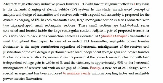
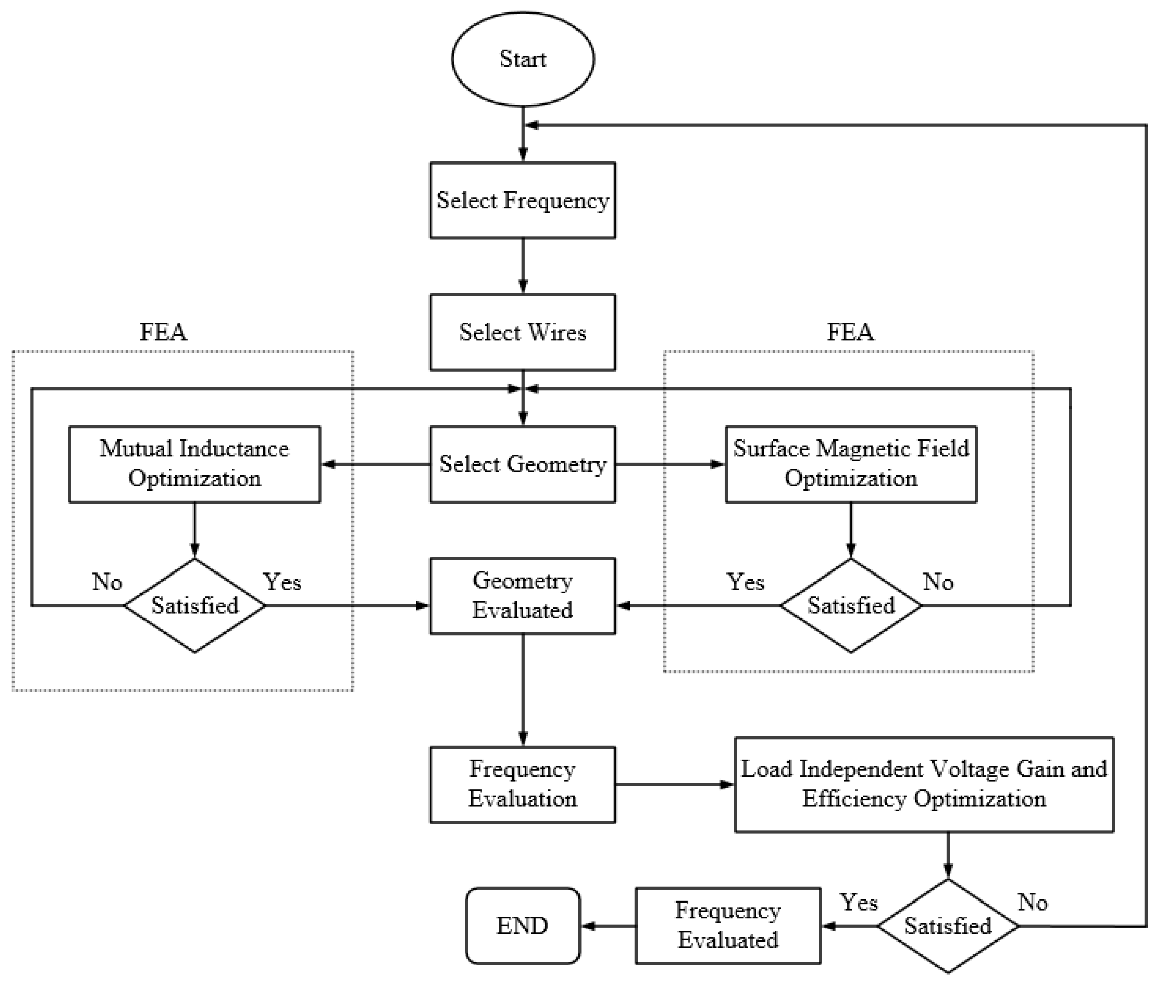
The flow chart of the design procedure of the magnetic pad is presented in Figure 1. Each of the transmitting and receiving coils has three rectangular sections as shown in Figure 2. The adjacent pair of transmitter coils with back-to-back series connection named extended DD transmitter is driven by a single source and presents a bipolar characteristic. Inside each section of the extended DD transmitter, two small rectangular sections of zigzag-shape are located with back-to-back series connection. Notably, the large rectangular section is also series connected with the small sections. A uniform magnetic flux distribution is obtained owing to the zigzag-shape. The identical current direction reinforces the magnetic fields of the neighboring transmitter coils; as a result, nearly stable mutual inductance occurs under receiver coil misalignment conditions. The extended DD transmitter presents bipolar characteristics and can thus eliminate the self-coupling between the transmitters [22]. In this study, the coils are made of litz wire. The thickness of coil is decided by the diameter of the litz wire. The diameter of the litz wire is selected by the current of coil, and the number of turns is chosen by the required output power. Litz wire contains 180 strands of AWG 38, and its total diameter is 1.85 mm with 0.35 mm-thick insulation of modified polyurethane for each turn. Ferrite plates are used with the transmitter and receiver to enhance the magnetic coupling. A 4 mm-thick ferrite plate is selected. The transmitter and receiver pads have an “I”-shaped ferrite plate leant on their external faces; thus, most flux lines are confined within the volume of these pads. The relative permeability and the magnetic loss tangent of the ferrite plate are chosen as 2300 and 0.008, respectively. Furthermore, aluminum shields are used behind the ferrite plate of each pad to reduce the unwanted leakage magnetic field [25]. The aluminum alloy used in this shield is 99.5% pure aluminum with conductivity σ of 33 MS/m. As a result, its skin depth δ at f = 80 kHz is calculated as δ = = 0.3 mm. The aluminum shield has a thickness of 1.2 mm, which is approximately 4 δ. The distance between ferrite plate and aluminum shield is set to 20 mm to reduce the eddy current loss in the aluminum shield. The vertical distance between transmitter and receiver (h) is maintained at 140 mm to minimize inductance variations due to their relative position.
In an actual case, the coil is built with rounded corners to realize a minimum bending radius. However, square corners are used in the current simulation to reduce the complexity of the proposed model. The length of each pad is determined by the length of the ferrite strips, number of coil turns, and the distance between the ferrite strips and the inner side of each width of the coil. The width is primarily determined by the number of coil turns, number of ferrite strips, and the spacing between two strips. The ferrite strip in each coil is composed of 5 × I43 plate cores, resulting in a total length of 215 mm. Depending on the number of coil turns and thickness of insulation of modified polyurethane for each turn, the distance between ferrite strip and inner side of each width of the coil is selected as 45.5 mm. The distance between two strips is selected as 67.2 mm. Each iterative simulation of FEA is conducted using four rows of ferrite strips of five “I”-shaped plate cores for each row.
3. Analysis of the Proposed Topology
3.1. Finite Element Analysis of Proposed Pad
Mutual inductance is a measure of the total flow of magnetic flux from one current carrying path that passes through another closed path. So that:
where, M(path1−path2) is the mutual inductance between path1 and path2, I(path1) is current of path1, N(path2) is the number of turns of path2 and Ø(path1−path2) is magnetic flux generated by path1 that links with path2.
Equation (1) is represented as:
where, B(path1) is magnetic flux density generated by I(path1), S(path2) is the surface of path2 and n is normal vector to the S(path2).
Using (1) and (2), mutual inductance is as follows:
That means, mutual inductance is directly related to the magnetic surface flux density (SFD).Therefore, coupling coefficient,
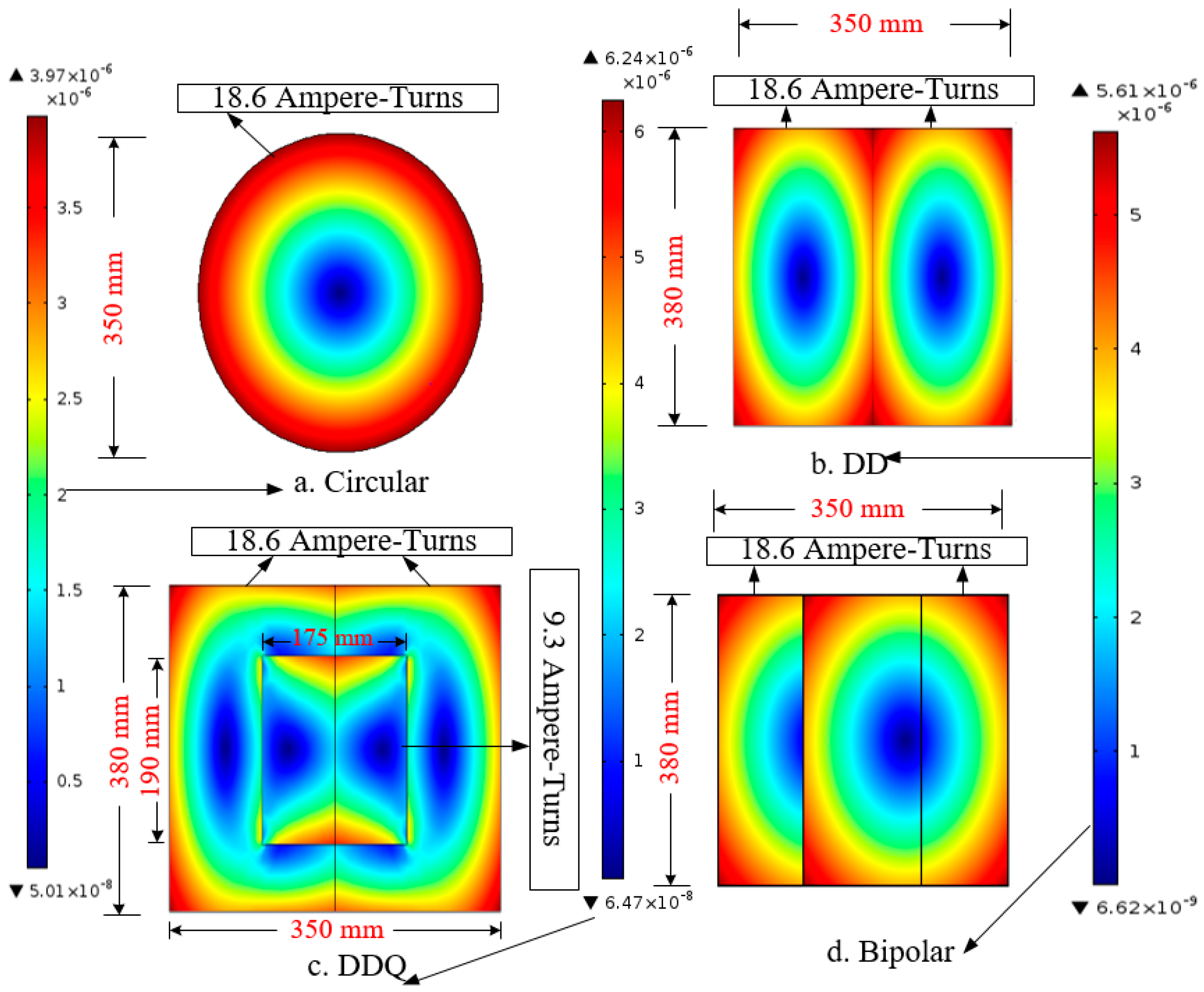
where, Lpath1 and Lpath2 are the inductances of path1 and path2 respectively. According to (3) and (4), it is clear that SFD has a great effect on the coupling coefficient. Negligible variation of coupling is very desirable for dynamic charging EV applications. This is possible if SFD is uniform over the whole charging area, so before the transmitter is made, mutual inductance can be conversely used to evaluate the uniformity of magnetic SFD. Magnetic SFD for different types of conventional coils with a frequency of 80 kHz is shown in Figure 3 using an FEA simulation tool of COMSOL.
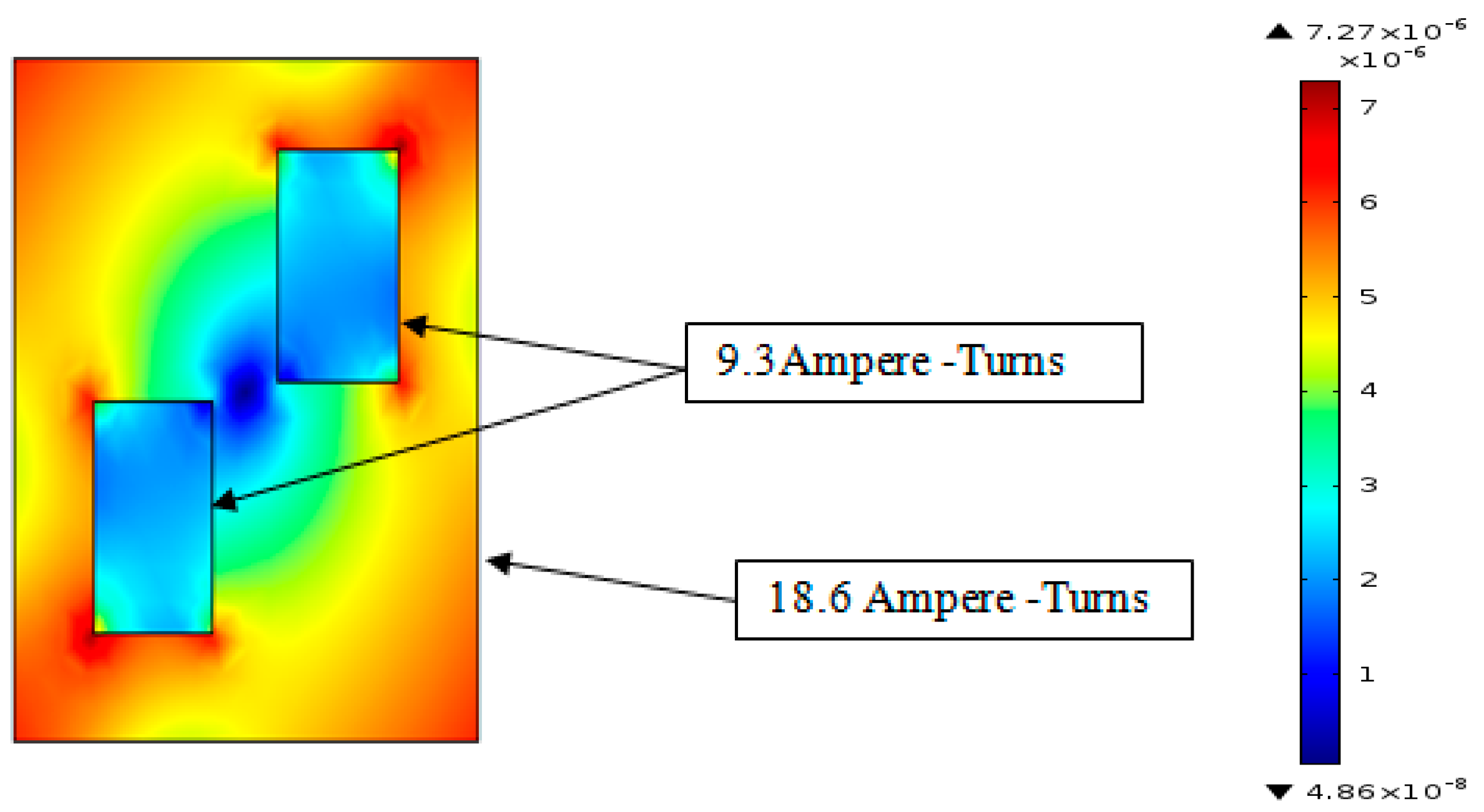
The design values of the optimum dimensions of the proposed coil are shown in Figure 2. The dimension of the larger section is 350 mm × 380 mm. Others are 100 mm × 130 mm. Here, the number of turns is selected as 10 and 5 for the large and small rectangle, respectively. Considering the effect of back-to-back connection of small rectangular sections, the magnetic SFD distribution for the proposed transmitter coil with same frequency like for Figure 3 is shown in Figure 4.
From Figure 3 and Figure 4, it is clear that the magnetic SFD of the proposed coil is almost uniformly distributed than in any other conventional coil. In addition, the magnetic SFD of the proposed coil is higher than in any other conventional coil. That means mutual inductance as well as coupling between the transmitter and receiver can be kept uniform with the proposed geometry. Due to this property, the power transfer fluctuations can be solved for different horizontal misalignment conditions, which will be verified by the Figure 17. The ferrite core which is used under each coil directs the main flux upwards. As a result, a single sided flux path is produced (i.e., no flux goes downwards behind the transmitter pad or upwards above the receiver pad). Using hypothesis (a), the magnetic flux density plot between transmitter and receiver pads is shown in Figure 5. Flux path height is observed to be 140 mm which is times the transmitter pad length.
In the case of the extended DD transmitter, mutual inductance for different misalignment positions of the receiver coil with respect to the transmitter coil position is simulated by FEA. In this finite-element analysis, the number of turns for large (Nlarge) and small (Nsmall) rectangular sections of each coil are considered.
From Figure 6, it is clear that maximum mutual inductance (LM) is about 36 µH when the number of turns for the large as well as the small rectangular sections is 10. Considering the cost of litz wire, number of turns is selected as 10 for the large section whereas it is 5 for the small sections. In this case, the mutual inductance is about 30 µH for different misalignment positions.
Considering a vertical air gap distance of 140 mm between the extended DD transmitter and the receiver, the uncompensated load power simulated by a frequency of 80 kHz is shown in Figure 7.
3.2. Mutual Inductance and Coupling Coefficient
The overall IPT system for EV charging in the case of the extended DD transmitter is shown in Figure 8. Here, Ll1 is the leakage inductance of the extended DD transmitter as stated before and the leakage inductance of the receiver coil is Ll2; C1, C2 and Cf2 are the compensation capacitors for Ll1, Ll2 and LMf respectively; LM is the mutual inductance between extended DD transmitter and receiver; Vi is the input dc supply for high frequency inverter and V0 is the voltage across the battery which resistance is RL. Lf and Cf are used after the high frequency rectifier for filtering purpose.
In dynamic charging EV systems, a huge waste of energy and prospective danger occur due to the conventional centralized power system. In addition the reduction of mutual inductance between transfer pads results in a reduction of transfer efficiency. Therefore, a design for both transmitter and receiver is developed to achieve a negligible fluctuation of the mutual inductance. To calculate the mutual inductance easily, Figure 6 is shifted by 90° as depicted in Figure 9.
Figure 9 shows the structure of two coils (transmitter and receiver) whose geometric centers are on the same vertical axis. Segments, ABCD and EFGH represent the transmitter and receiver coils respectively. Here, the center of transmitter is set as the ordinate origin (0, 0, 0), while the coordinate of the receiver coil center is (0, s, h) [26]. Several segments are associated with both coils and mutual inductances are calculated based on this. Here, AB = CD = 2a1, BC = AD = 2b1, EF = GH = 2a2, EH = FG = 2b2. Large rectangular section of transmitter is represented as 1 whereas, 1′ for large rectangular section of receiver. On the other hand, (2, 3) and (2′, 3′) are for smaller sections of transmitter and receiver respectively.
Considering unit vectors for each section of transmitter and receiver:
Define:
where,
Considering, the pad-currents of the transmitter and receiver are I1 and I2 respectively. Therefore, the magnetic flux generated by NAB turns of AB segment that links with segment EF is derived as:
where:
Using (11):
Also, the magnetic flux generated by NEF turns of EF segment that links with segment AB is expressed as:
where:
From (14):
Using (13) and (16), mutual inductance between AB & EF is represented as:
Using hypothesis (b), the mutual inductance between two larger rectangular sections (1 and 1′) is calculated as: [27]
Considering, = = 10 = and = = = = 5 = ; the above equation is modified as:
Similarly, other mutual inductances are derived as:
With the aid of the above equations, the mutual inductance (LM1) between transmitter (ABCD) and receiver (EFGH) can be calculated [28]. In the case of the extended DD transmitter, the mutual inductance (LM) is given as:
where, LM2 is the mutual inductance between another part of extended DD transmitter and the receiver, so that the effective coupling coefficient is:
LM = LM1 + LM2
Here, LT is the inductance of the extended DD transmitter, and the inductance of the receiver is LR. As discussed earlier in the section, LM is almost constant in every horizontal misalignment position of the receiver, which is desirable for dynamic charging of EV applications. In view of this fact, negligible coupling changes can be achievable in each horizontal misalignment position.
3.3. Load Independent Voltage Gain
In this section, the analysis of voltage gain and zero phase angle (ZPA) of the input impedance at load independent frequency is presented. In this case, we choose the T-model for the IPT transformer with turn ratio 1:n. In the case of an S-SP compensated resonant converter [29], another capacitor, Cf2 for compensating LM is launched for the S-S compensated resonant converter. Here, higher order harmonics are injected into the rectifier network even though ZPA of the input impedance and load independent voltage gain are obtained. To minimize the higher order harmonics, those are injected into the rectifier network, and another inductor Lf2 parallel with LM is introduced to the S-SP compensated resonant converter. In this case, Cf2 compensates the equivalent parallel inductance of n2LM and Lf2.This equivalent inductance was already expressed in Equation (5).
The equivalent circuit of the IPT system using an LC-LC2 compensation network with the aid of the T-model is shown in Figure 10. The above equivalent inductance and all leakage inductances of the proposed compensation-based IPT transformer are compensated at once:
where, ωr is the resonant frequency.C1, C2 and Cf2 represent the compensation capacitors of Ll1, Ll2 and LMf respectively.
Load independent voltage gain and ZPA of the input impedance of the proposed IPT transformer using LC-LC2 compensation have been explained briefly with the aid of Figure 8.
Using Kirchhoff’s voltage law, the fundamental components of , VAB and Vab can be represented as:
where = equivalent ac load resistance looking into the high frequency rectifier, and .
With the aid of Fourier analysis, VAB can be depicted as:
Because of Lf2, most of the higher order harmonics that tend to be injected into the rectifier can be eliminated. Consequently, Vab can be considered as a sine wave. Therefore, the voltage across the battery can be simplified as:
From (31)–(34), the voltage gain of the LC-LC2 compensated resonant converter can be written as:
where and:
Equation (38) can be expressed as:
From (35), it is clear that voltage gain is independent of load when δ = 0.
Using δ = 0, we get two load independent voltage gain frequencies:
where and
The voltage gain at the above frequencies can be obtained as:
Considering that, load independent voltage gain frequency is ωr. To get a constant voltage gain at ωr, the following equation should be fulfilled:
By putting and δ = 0 into (44), gives:
Therefore, . Substituting into (39), we get:
so that a load independent constant voltage gain with no coupling coefficient effect is obtained when .
The input impedance of the proposed IPT pad based resonant converter is calculated as:
Substituting into (47), yields:
In order to obtain ZPA of Zi at ωr, the following imaginary part should be equal to zero. The imaginary part of the input impedance of (48) can be obtained as:
Under the full compensation, (40) and (41) yields:
Equation (51) follows Equation (30). Therefore, the constant voltage gain and ZPA of the input impedance both can be obtained, under the full compensation () conditions. This is a recommended characteristic to obtain high efficiency and good controllability of the output voltage. From (35), the required constant voltage gain can be calculated as:
4. Experimental Results and Discussion
To get the load independent unique voltage gain, it is necessary to design a system with almost negligible mutual inductance changes under a large range of misalignment conditions. The measured coupling coefficient according to the changes of receiver coil position is shown in Figure 11. Here, the coupling coefficient is measured between the extended DD transmitter and the receiver pad. It is noted that the coupling variation is within ±7%.
The design specifications of dynamic charging EV systems are found by considering the fundamental component of VAB, which are listed in Table 1.
In Table 1, the value of the compensating inductor and the resonant capacitors are derived with the help of Equations (5) and (30). To get high efficiency, not only is a high coupling coefficient important but also a high quality factor of the coil is needed. The quality factor of the extended DD transmitter and receiver coils are found as 247 ( and 282 ( respectively, with the help of Table 1, which are enough to achieve the desired high efficiency.
Figure 12 depicts the measured phase angle of the input impedance with the specifications listed in Table 1. From the figure, it is clear that load independent ZPA of the input impedance is obtained when the proposed IPT transformer is fully compensated.
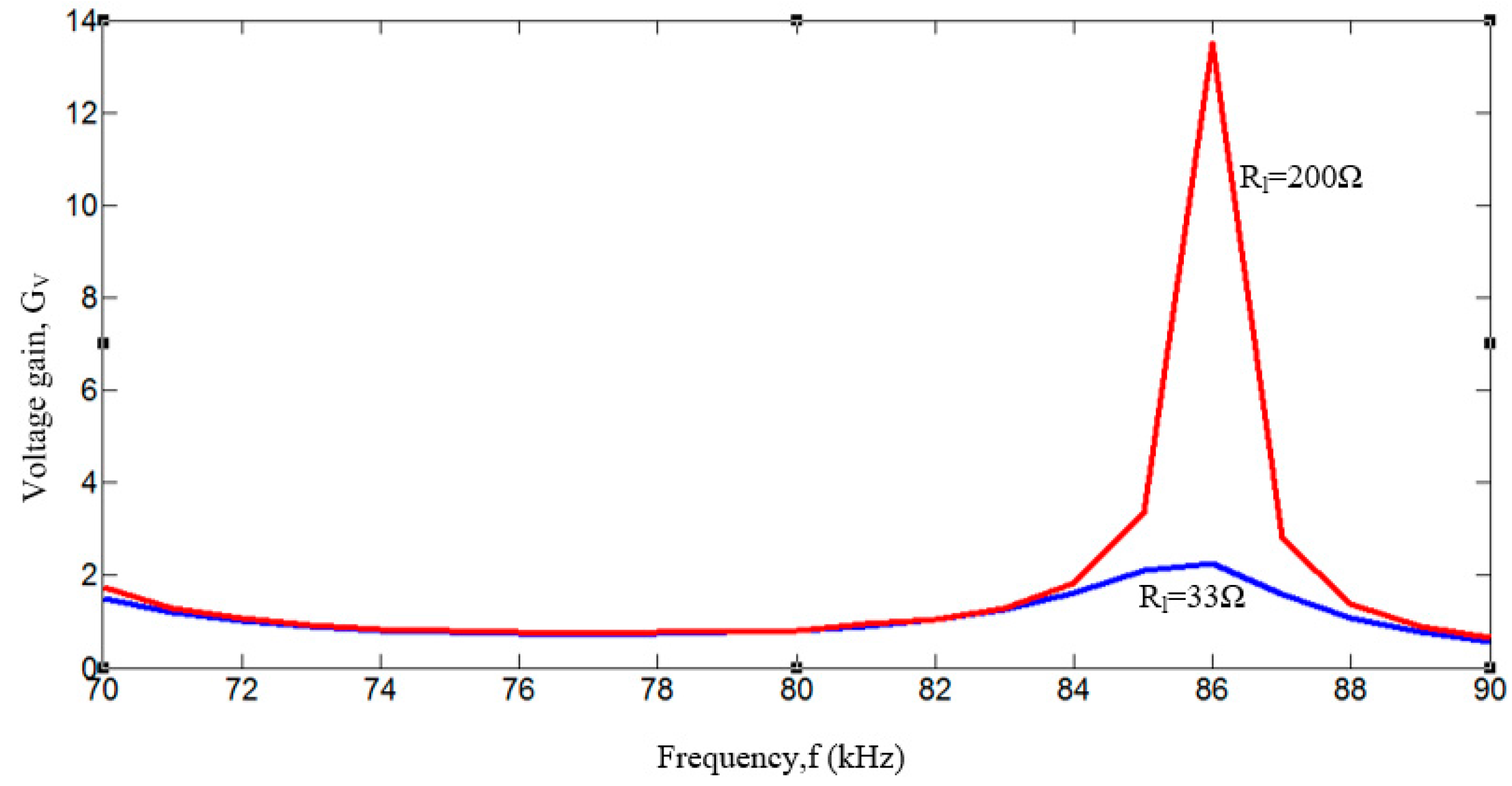
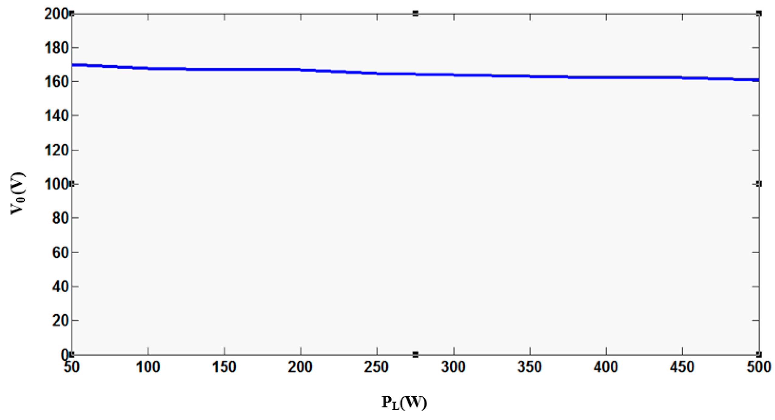
The measured voltage gain corresponding to the frequency is depicted in Figure 13. Comparing Figure 12 and Figure 13; we can say that load independent voltage gain and ZPA of the input impedance can both be obtained at the frequency of ωH. The experimental load regulation curve of the proposed magnetic pad based LC-LC2 compensated IPT system is shown in Figure 14.
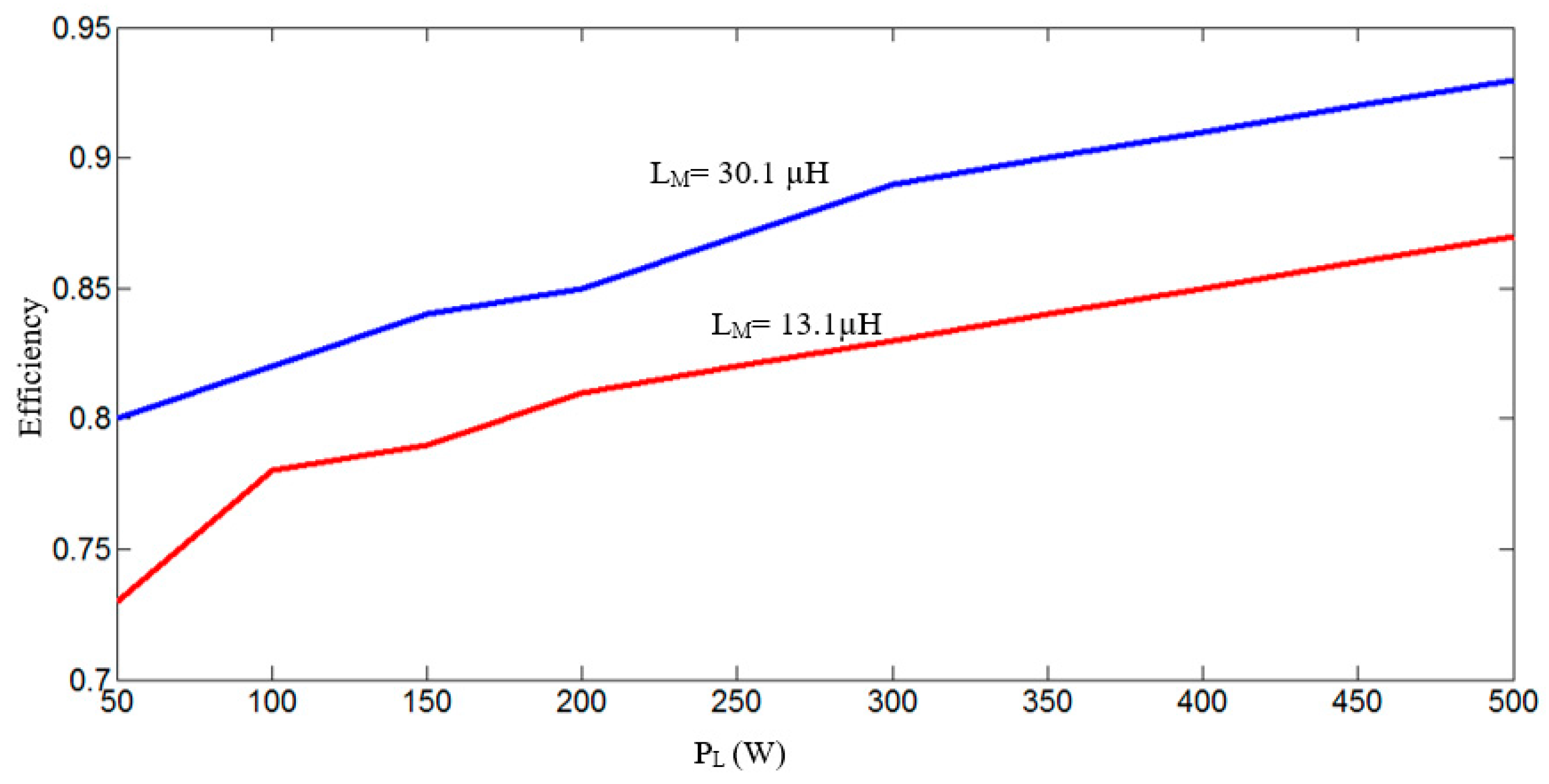
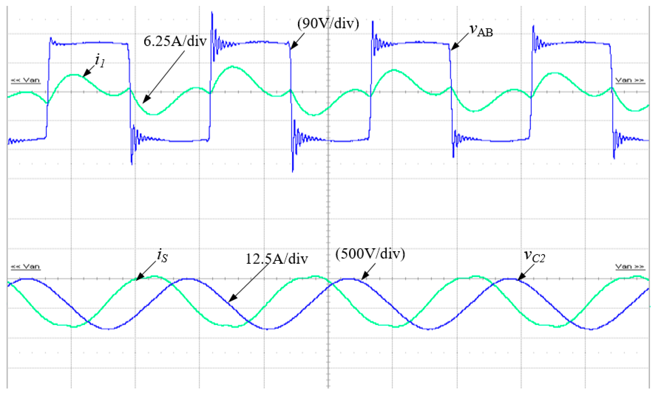
The experimental efficiency from dc supply to the battery, measured for given mutual inductance as well as another mutual inductance (13.1 µH) with another air gap (180 mm) is shown in Figure 15. Laboratory results of the proposed and LC-LC2 compensated IPT system under specific frequency control is also depicted in Figure 16.
Long transmitters present considerable power transfer fluctuation because of the low coupling coefficient when the receiver coil moves along the transmitter. In the case of segmented transmitter coils, if each coil is spaced by a small distance [17] and separately powered on, fluctuation also exists as well as high coupling coefficient and higher efficiency than with the long transmitter layout are obtained. In this case, zero power transfer occurs at certain positions of the receiver coil, making the method unsuitable for dynamic charging. Even when all transmitter coils are apart from each other with zero distance and are separately supplied with power, power transfer fluctuation still occurs. This situation is also true for coils connected in parallel and supplied with a common power supply [18]. This design eliminates the null power transfer zone but is less effective for dynamic charging systems.
A method for dynamic charging is proposed in this study. In this method, when the receiver coil is perfectly aligned on any of the proposed transmitter coils, the adjacent coil is back-to-back series connected with the previous one and supplied by the source. When the receiver coil fully crosses the first transmitter coil, the first transmitter coil is turned off and the third transmitter coil is again back-to-back series connected with the second one and supplied by the power supply as before. This sequence is continued with all primary transmitter coils buried under the road. When the receiver coil is fully aligned with the first transmitter coil, the power transfer rate is approximately 93% of the power supply until the third transmitter coil is turned on. Apart from the proposed method of dynamic charging, the power transfer fluctuation is within ±6% for different horizontal misalignment (x-direction) positions of receiver coil (Figure 17).
Figure 17 shows that this method provides negligible power transfer fluctuation with no null zone situation of power. To conclude, this method is helpful to acquire almost constant power transfer for dynamic charging of EV applications. The key points of the proposed pad compared to the conventional geometry of the pads are explained using Table 2.
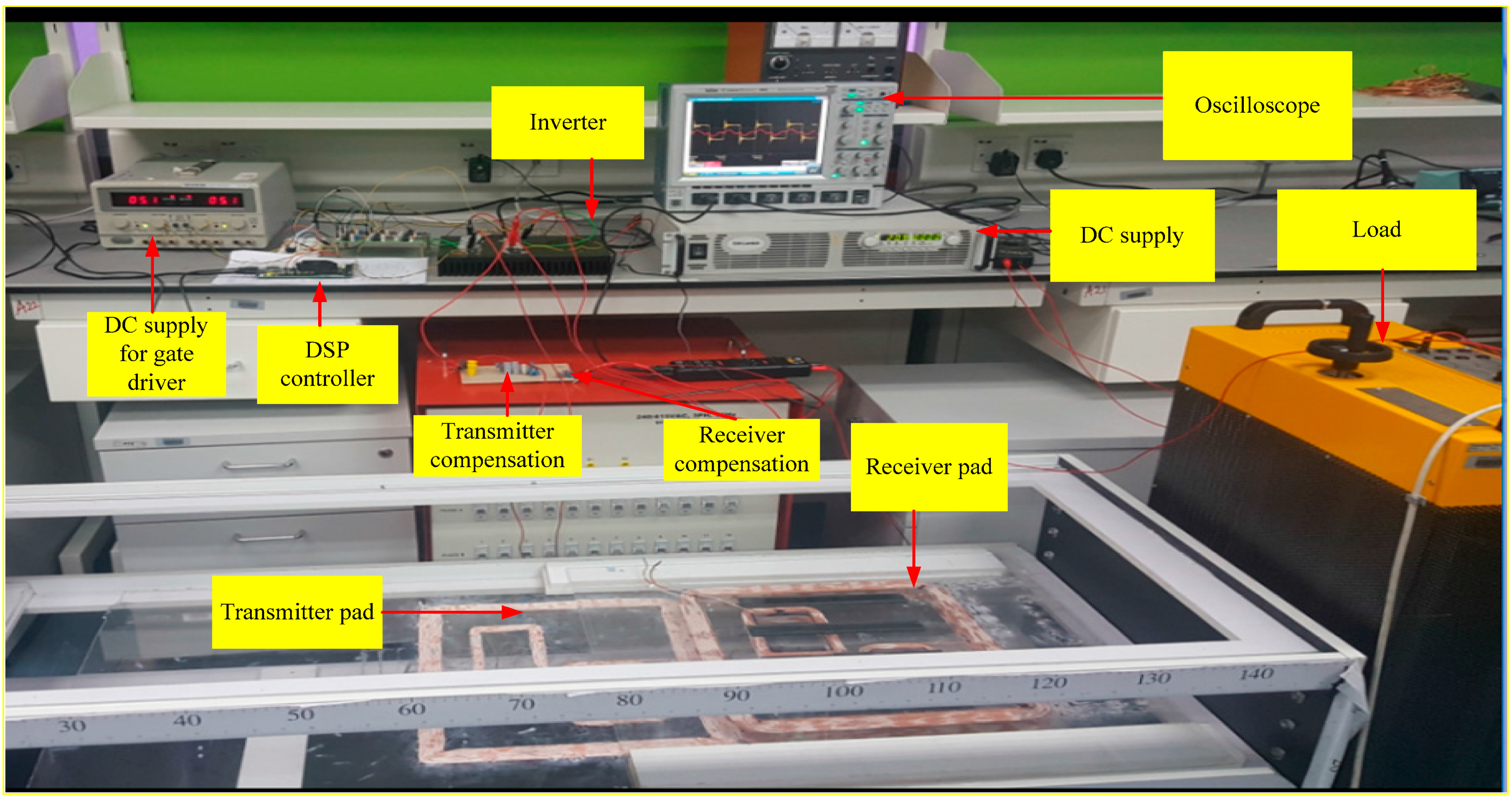
The overall experimental laboratory setup for the proposed dynamic charging system of electric vehicles is shown in Figure 18.
Future works can conduct predictive diagnosis to achieve continuous power supply from high-frequency inverters to the transmitter pads [33,34]. Mechanisms for protection and safe diagnosis of power system components can also be proposed [35]. Furthermore, proposed systems can be interfaced to the home part of the smart grid if the EV must be recharged at home [36].
5. Conclusions
In this study, a new coil design with a special arrangement has been proposed for maintaining nearly uniform coupling factors and negligible power transfer fluctuation. This coil arrangement is effective, especially for dynamic charging of EVs. The coil design has been fully explained with the help of FEA. This study contributes to the literature by obtaining uniform magnetic flux distribution produced by the zigzag-shape of the small rectangular sections located inside the large rectangular section. Negligible power transfer fluctuation with a slight variation in coupling is obtained even under horizontal misalignment of the receiver coil. This major contribution of the study has been justified for the extended DD transmitter by the aid of load-independent voltage transfer ratio and power transfer fluctuation analysis. A nearly uniform power transfer efficiency of 93% has been achieved at a load independent constant voltage gain frequency of 80 kHz, under the horizontal (x-direction) misalignment of receiver coil with 140 mm vertical air gap distance between the transmitter and receiver. A simple process to select the suitable switching position of the extended DD transmitters has been recommended on the basis of the receiver coil position for sequential operation of all transmitter coils buried under the road.
Acknowledgments
This work was supported by the High Impact Research of the University of Malaya—Ministry of Higher Education of Malaysia under Project UM.C/HIR/MOHE/ENG/24 and Postgraduate Research Grant (PPP) No. PG156-2016A.
Author Contributions
Md Morshed Alam has contributed to the theoretical approaches, simulation, experimental tests, and preparing the article; Saad Mekhilef has contributed to the experimental tests and preparing the article; Mehdi Seyedmahmoudian has contributed to the theoretical approaches and preparing the article; Ben Horan has contributed to the theoretical approaches and preparing the article.
Conflicts of Interest
The authors declare no conflict of interest.
References
- Jeong, S.; Jang, Y.J.; Kum, D. Economic Analysis of the dynamic charging electric vehicle. IEEE Trans. Power Electron. 2015, 30, 6368–6377. [Google Scholar] [CrossRef]
- Jan-Mou, L.; Jones, P.T.; Onar, O.; Starke, M. Coupling electric vehicles and power grid through charging-in-motion and connected vehicle technology. In Proceedings of the IEEE Electric Vehicle Conference (IEVC), Florence, Italy, 17–19 December 2014. [Google Scholar]
- Gilchrist, A.; Wu, H.; Sealy, K. Novel system for wireless in-motion EV charging and disabled vehicle removal. In Proceedings of the IEEE Electric Vehicle Conference (IEVC), Greenville, SC, USA, 4–8 March 2012. [Google Scholar]
- Stamati, T.E.; Bauer, P. On-road charging of electric vehicles. In Proceedings of the IEEE Transportation Electrification Conference and Expo (ITEC), Metro Detroit, MI, USA, 16–19 June 2013. [Google Scholar]
- Prasanth, V.; Bauer, P. Study of misalignment for on road charging. In Proceedings of the IEEE Transportation Electrification Conference and Expo (ITEC), Metro Detroit, MI, USA, 16–19 June 2013. [Google Scholar]
- Zhang, W.; Wong, S.-C.; Tse, C.K.; Chen, Q. An optimized track length in roadway inductive power transfer systems. IEEE J. Emerg. Sel. Top. Power Electron. 2014, 2, 598–608. [Google Scholar] [CrossRef]
- Kalwar, A.K.; Mekhilef, S.; Seyedmahmoudian, M.; Horan, B. Coil design for high misalignment tolerant inductive power transfer system for EV charging. Energies. 2016, 9, 937. [Google Scholar] [CrossRef]
- Bosshard, R.; Kolar, J.W.; Muhlethaler, J.; Stevanovic, I.; Wunsch, B.; Canales, F. Modeling and η-α-pareto optimization of inductive power transfer coils for electric vehicles. IEEE J. Emerg. Sel. Top. Power Electron. 2015, 3, 50–64. [Google Scholar] [CrossRef]
- Kalwar, A.K.; Aamir, M.; Uddin, K.M.; Mekhilef, S. A new coil design for enhancement in misalignmenttolerance of wireless charging system. In Proceedings of the Students Conference on Research and Development (SCOReD), Kuala Lumpur, Malaysia, 13–14 December 2015. [Google Scholar]
- Elliott, G.A.J.; Covic, G.A.; Kacprzak, D.; Boys, J.T. A new concept: Asymmetrical pick-ups for inductively coupled power transfer monorail systems. IEEE Trans. Magn. 2006, 42, 3389–3391. [Google Scholar] [CrossRef]
- Shin, J.; Shin, S.; Kim, Y.; Ahn, S.; Lee, S.; Jung, G.; Jeon, S.-J.; Cho, D.-H. Design and implementation of shaped magnetic-resonance-based wireless power transfer system for roadway-powered moving electric vehicles. IEEE Trans. Ind. Electron. 2014, 61, 1179–1192. [Google Scholar] [CrossRef]
- Prasanth, V.; Bauer, P. Distributed IPT systems for dynamic powering: Misalignment analysis. IEEE Trans. Ind. Electron. 2014, 61, 6013–6021. [Google Scholar] [CrossRef]
- Pijl, F.F.A.v.d.; Castilla, M.; Bauer, P. Adaptive sliding-mode control for a multiple-user inductive power transfer system without need for communication. IEEE Trans. Ind. Electron. 2013, 60, 271–279. [Google Scholar] [CrossRef]
- Onar, O.C.; Miller, J.M.; Campbell, S.; Coomer, C.; White, C.; Seiber, L. A novel wireless power transfer for in-motion EV/PHEV charging. In Proceedings of the Twenty-Eighth Annual IEEE Applied Power Electronics Conference and Exposition (APEC), Long Beach, CA, USA, 17–21 March 2013. [Google Scholar]
- Onar, O.C.; Miller, J.M.; Campbell, S.; Coomer, C.; White, C.; Seiber, L.; Sepe, R.; Steyerl, A. Demonstrating dynamic wireless charging of an electric vehicle: The benefit of electrochemical capacitor smoothing. IEEE Power Electron. Magn. 2014, 1, 12–24. [Google Scholar]
- Sampath, J.P.K.; Vilathgamuwa, D.M.; Alphones, A. Efficiency enhancement for dynamic wireless power transfer system with segmented transmitter array. IEEE Trans. Transp. Electrif. 2015, 2, 76–85. [Google Scholar] [CrossRef]
- Miller, J.M.; Jones, P.T.; Jan-Mou, L.; Onar, O.C. ORNL experience and challenges facing dynamic wireless power charging of EV’s. IEEE Circuits Sys. Mag. 2015, 15, 40–53. [Google Scholar] [CrossRef]
- Kibok, L.; Pantic, Z.; Lukic, S.M. Reflexive field containment in dynamic inductive power transfer systems. IEEE Trans. Power Electron. 2014, 29, 4592–4602. [Google Scholar]
- Chen, L.; Nagendra, G.R.; Boys, J.T.; Covic, G.A. Double-coupled systems for IPT roadway applications. IEEE J. Emerg. Sel. Top. Power Electron. 2015, 3, 37–49. [Google Scholar] [CrossRef]
- Budhia, M.; Covic, G.A.; Boys, J.T. Design and optimization of circular magnetic structures for lumped inductive power transfer systems. IEEE Trans. Power Electron. 2011, 26, 3096–3108. [Google Scholar] [CrossRef]
- Budhia, M.; Boys, J.T.; Covic, G.A.; Chang-Yu, H. Development of a single-sided flux magnetic coupler for electric vehicle ipt charging systems. IEEE Trans. Ind. Electron. 2013, 60, 318–328. [Google Scholar] [CrossRef]
- Covic, G.A.; Kissin, M.L.G.; Kacprzak, D.; Clausen, N.; Hao, H. A bipolar primary pad topology for EV stationary charging and highway power by inductive coupling. In Proceedings of the IEEE Energy Conversion Congress and Exposition (ECCE), Phoenix, AZ, USA, 17–22 September 2011. [Google Scholar]
- Budhia, M.; Covic, G.A.; Boys, J.T.; Chang-Yu, H. Development and evaluation of single sided flux couplers for contactless electric vehicle charging. In Proceedings of the IEEE Energy Conversion Congress and Exposition (ECCE), Phoenix, AZ, USA, 17–22 September 2011. [Google Scholar]
- Zhu, Q.; Wang, L.; Guo, Y.; Liao, C.; Li, F. Applying LCC compensation network to dynamic wireless EV charging system. IEEE Trans. Ind. Electron. 2016, 63, 6557–6567. [Google Scholar] [CrossRef]
- Wen, F.; Huang, X. Optimal magnetic field shielding method by metallic sheets in wireless power transfer system. Energies 2016, 9, 733. [Google Scholar] [CrossRef]
- Chen, Z.; Jing, W.; Huang, X.; Tan, L.; Chen, C.; Wang, W. A promoted design for primary coil in roadway-powered system. IEEE Trans. Magn. 2015, 51, 1–4. [Google Scholar] [CrossRef]
- Greenhouse, H.M. Design of planar rectangular microelectronic inductors. IEEE Trans. Parts Hybrids Packag. 1974, 10, 101–109. [Google Scholar] [CrossRef]
- Cheng, Y.; Shu, Y. A new analytical calculation of the mutual inductance of the coaxial spiral rectangular coils. IEEE Trans. Magn. 2014, 50, 1–6. [Google Scholar] [CrossRef]
- Hou, J.; Chen, Q.; Yan, K.; Ren, X.; Wong, S.C.; Tse, C.K. Analysis and control of S/SP compensation contactless resonant converter with constant voltage gain. In Proceedings of the IEEE Energy Conversion Congress and Exposition (ECCE), Denver, CO, USA, 15–19 September 2013. [Google Scholar]
- Budhia, M.; Covic, G.A.; Boys, J.T. A new IPT magnetic coupler for electric vehicle charging systems. In Proceedings of the 36th Annual Conference on IEEE Industrial Electronics Society, Glendale, AZ, USA, 7–10 November 2010. [Google Scholar]
- Li, S.; Mi, C.C. Wireless power transfer for electric vehicle applications. IEEE J. Emerg. Sel. Top. Power Electron. 2015, 3, 4–17. [Google Scholar]
- Zaheer, A.; Kacprzak, D.; Covic, G.A. A bipolar receiver pad in a lumped IPT system for electric vehicle charging applications. In Proceedings of the IEEE Energy Conversion Congress and Exposition (ECCE), Raleigh, NC, USA, 15–20 September 2012. [Google Scholar]
- Saponara, S. Distributed measuring system for predictive diagnosis of uninterruptible power supplies in safety-critical applications. Energies 2016, 9, 327. [Google Scholar] [CrossRef]
- Saponara, S.; Fanucci, L.; Bernardo, F.; Falciani, A. Predictive diagnosis of high-power transformer faults by networking vibration measuring nodes with integrated signal processing. IEEE Trans. Instrum. Meas. 2016, 65, 1749–1760. [Google Scholar] [CrossRef]
- Costantino, N.; Serventi, R.; Tinfena, F.; D’Abramo, P.; Chassard, P.; Tisserand, P.; Saponara, S.; Fanucci, L. Design and test of an HV-CMOS intelligent power switch with integrated protections and self-diagnostic for harsh automotive applications. IEEE Trans. Ind. Electron. 2011, 58, 2715–2727. [Google Scholar] [CrossRef]
- Saponara, S.; Bacchillone, T. Network architecture, security issues, and hardware implementation of a home area network for smart grid. J. Comput. Netw. Commun. 2012, 2012, 534512. [Google Scholar] [CrossRef]
Figure 1.
Design procedure of the proposed magnetic pad.

Figure 2.
Optimum dimension of the proposed coil.

Figure 3.
Magnetic surface flux density of different conventional shape coils.

Figure 4.
Magnetic surface flux density (T) of proposed coil.

Figure 5.
Magnetic flux density distribution with proposed pad.
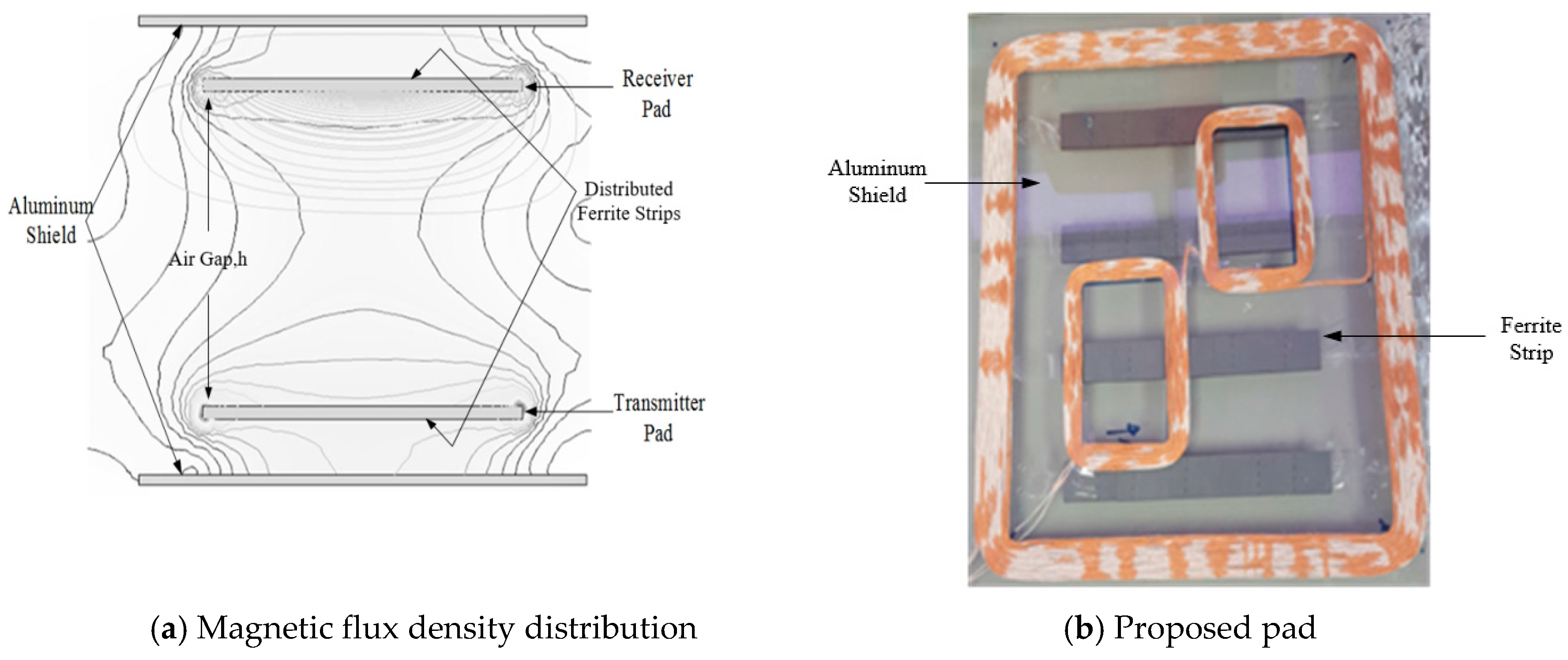
Figure 6.
Observation of mutual inductance for different horizontal (x-direction) misalignment positions of the receiver coil.
Figure 6.
Observation of mutual inductance for different horizontal (x-direction) misalignment positions of the receiver coil.
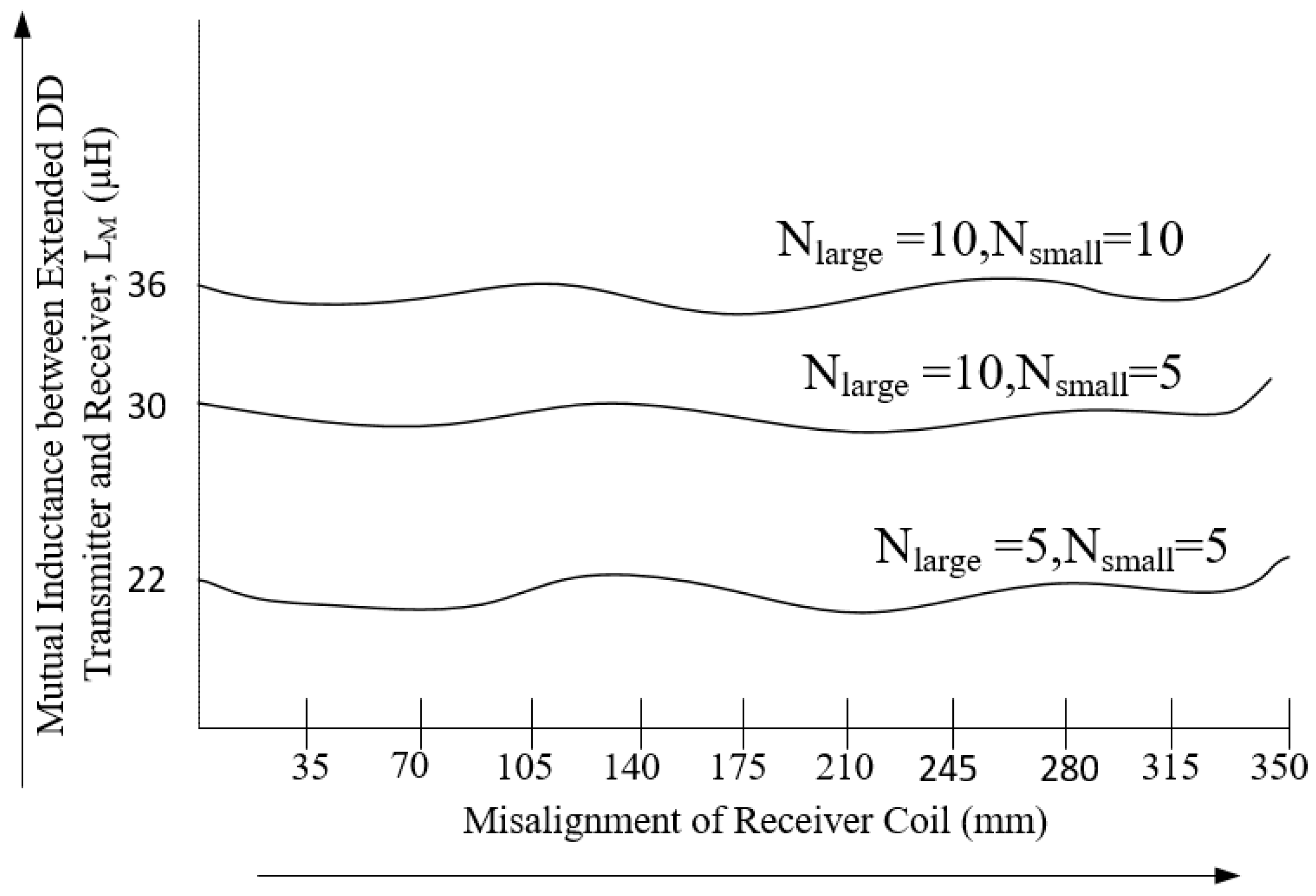
Figure 7.
Uncompensated load power for different horizontal (x-direction) misalignment positions of the receiver coil.
Figure 7.
Uncompensated load power for different horizontal (x-direction) misalignment positions of the receiver coil.
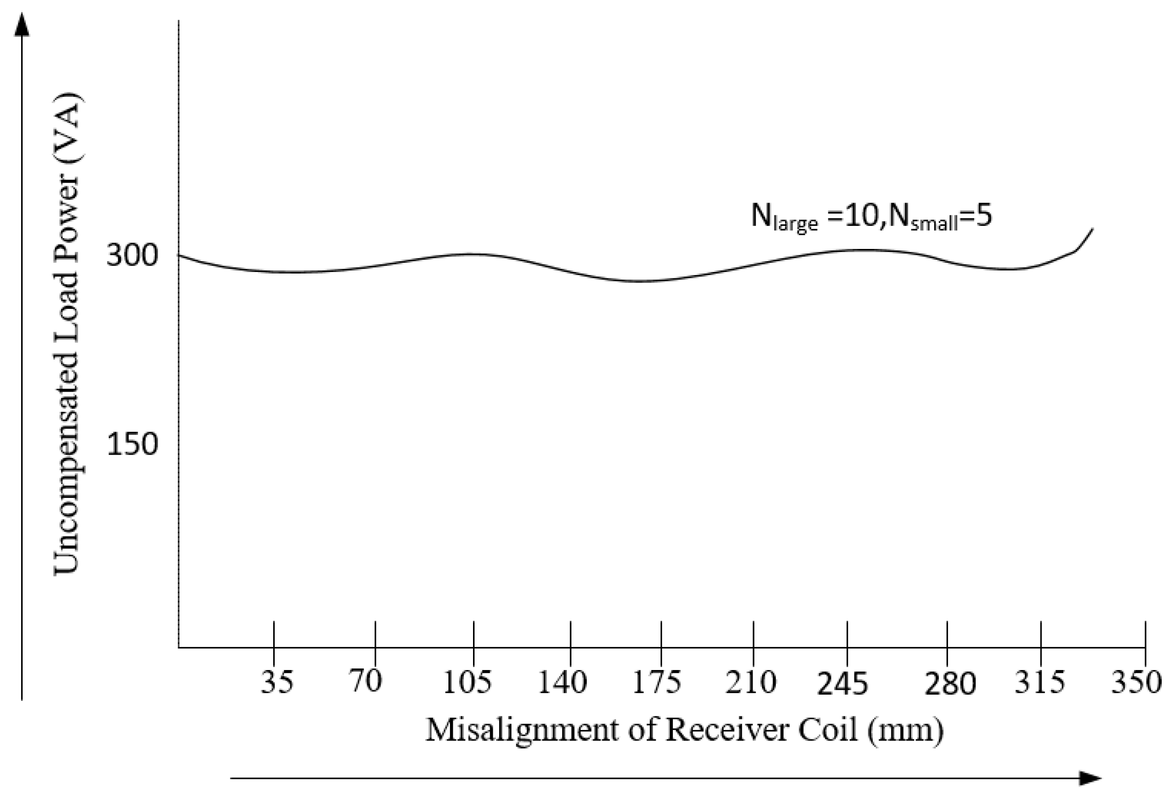
Figure 8.
Overall inductive power transfer system for electric vehicle charging.
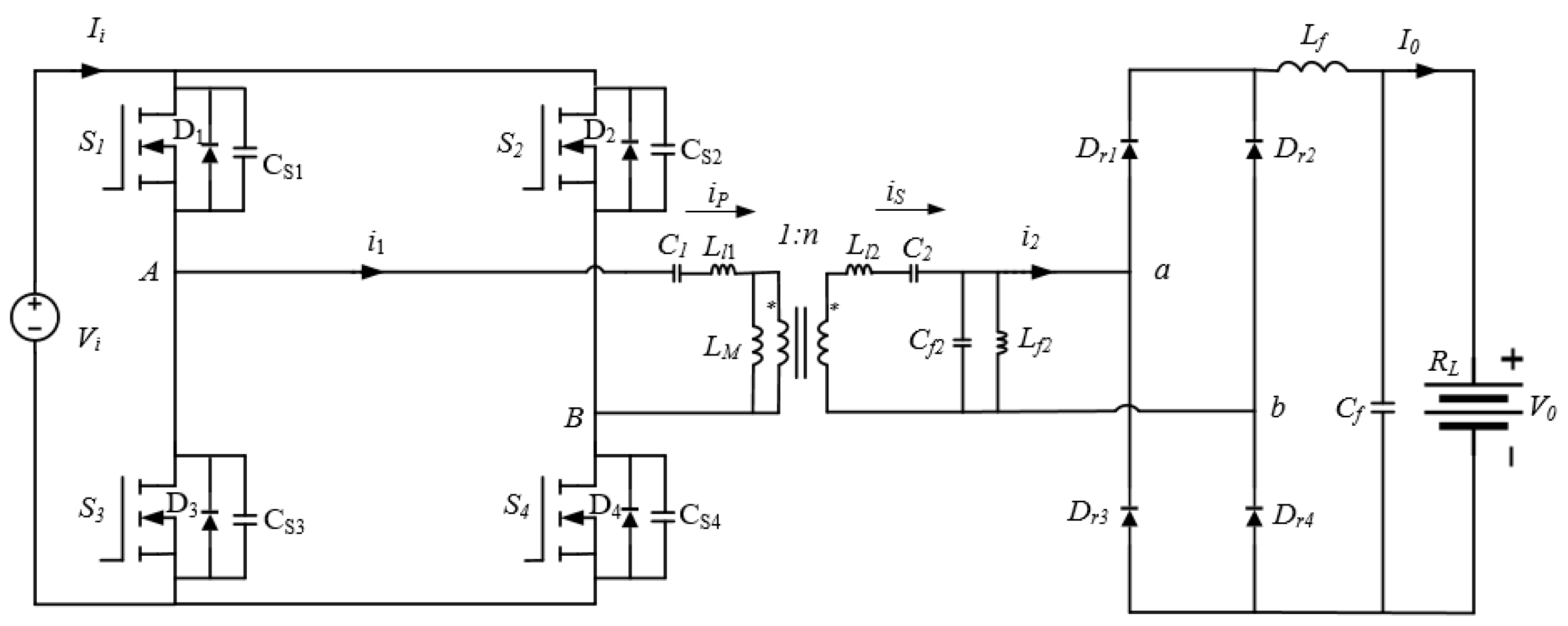
Figure 9.
Schematic overview of proposed transmitter and receiver coils.
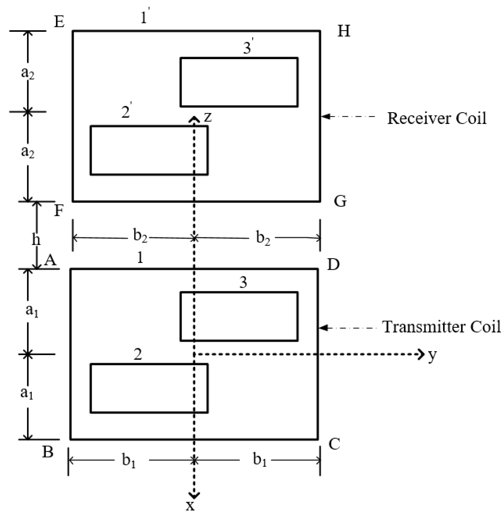
Figure 10.
Equivalent circuit of the IPT system using LC-LC2 compensation network.
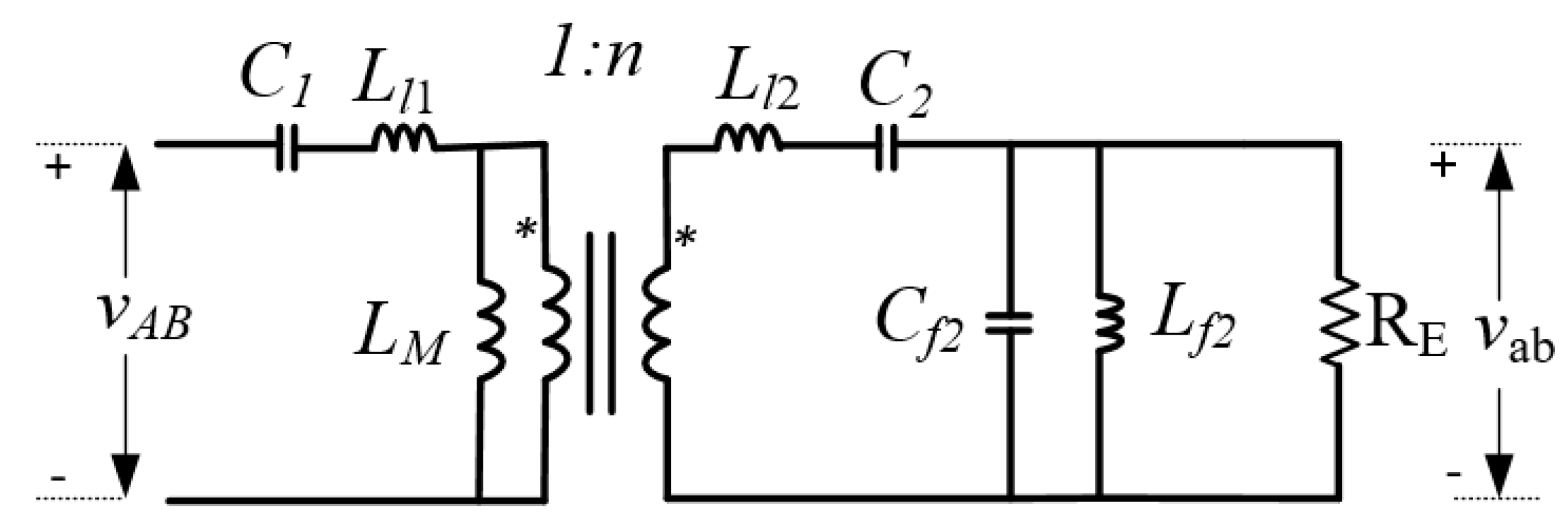
Figure 11.
Measured coupling coefficient with different receiver coil positions (x-direction).
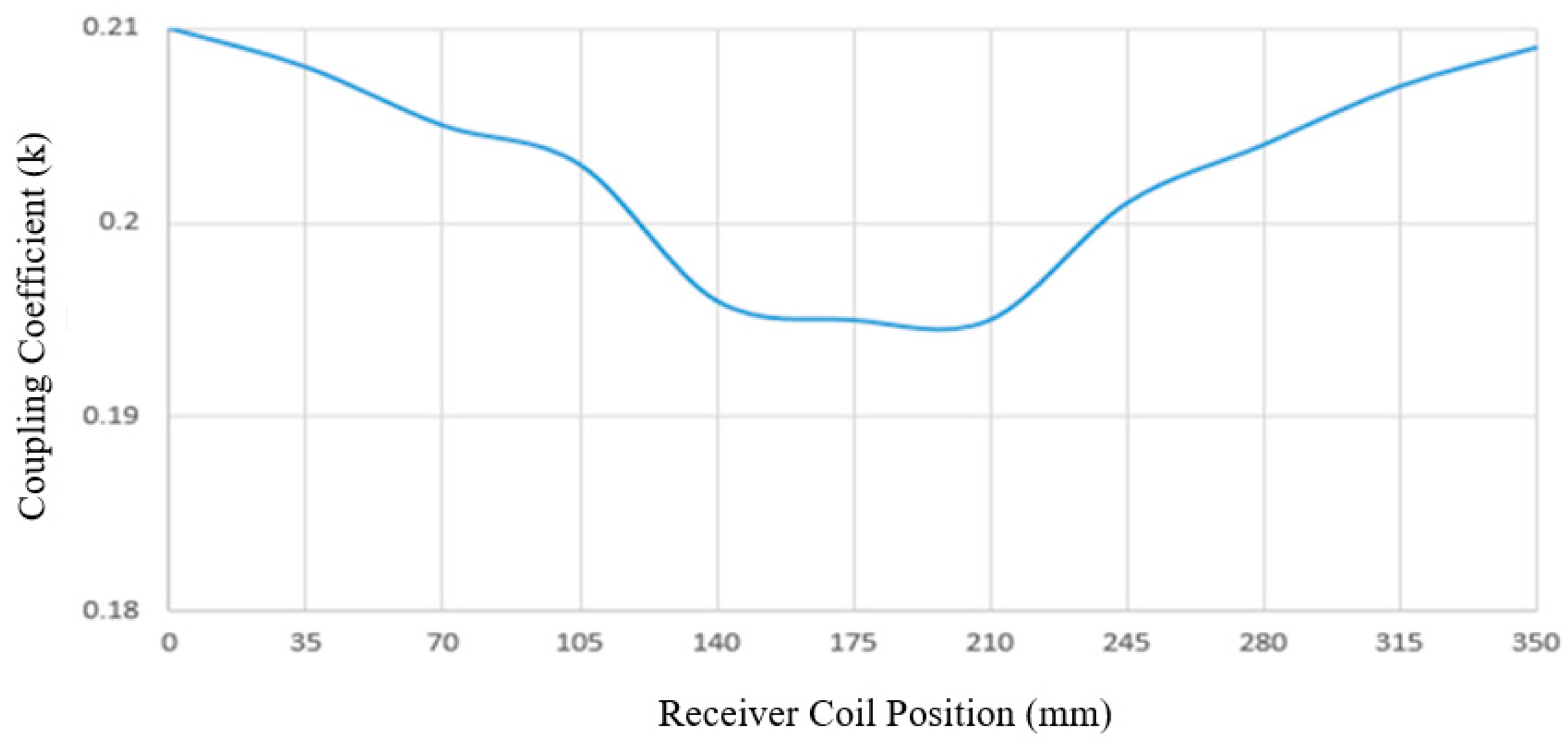
Figure 12.
Measured input phase angle of the 500 W LC-LC2 compensated IPT system for EV charging.
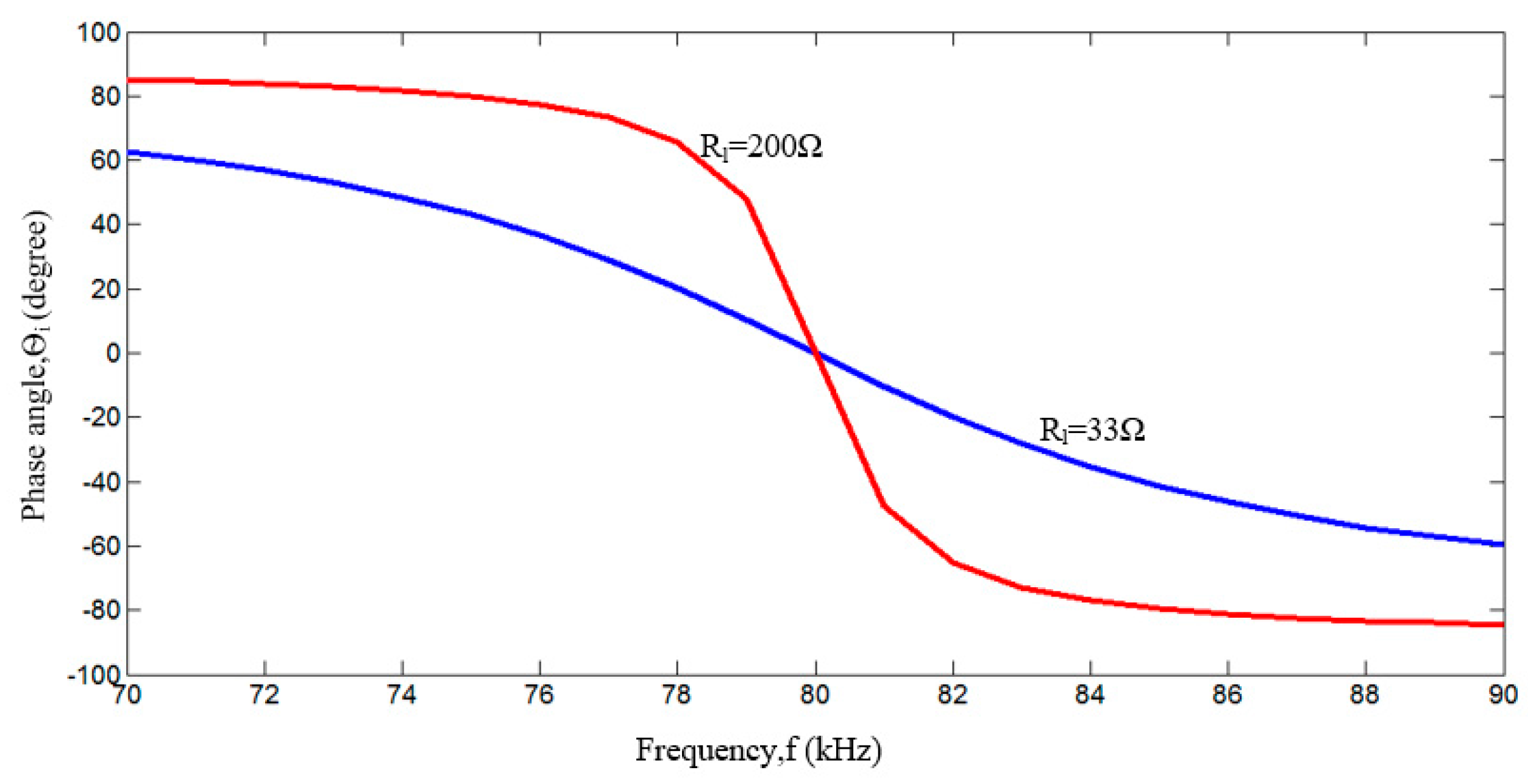
Figure 13.
Measured voltage gain of the 500 W LC-LC2 compensated IPT system for EV charging.

Figure 14.
Measured load regulation of the 500 W LC-LC2 compensated IPT system for the proposed magnetic pad.
Figure 14.
Measured load regulation of the 500 W LC-LC2 compensated IPT system for the proposed magnetic pad.

Figure 15.
Efficiency of the 500 W LC-LC2 compensated IPT system for proposed magnetic pad.

Figure 16.
Laboratory results of the proposed and LC-LC2 compensated IPT system under specific frequency control.
Figure 16.
Laboratory results of the proposed and LC-LC2 compensated IPT system under specific frequency control.

Figure 17.
Measured load power under different receiver coil positions (x-direction).
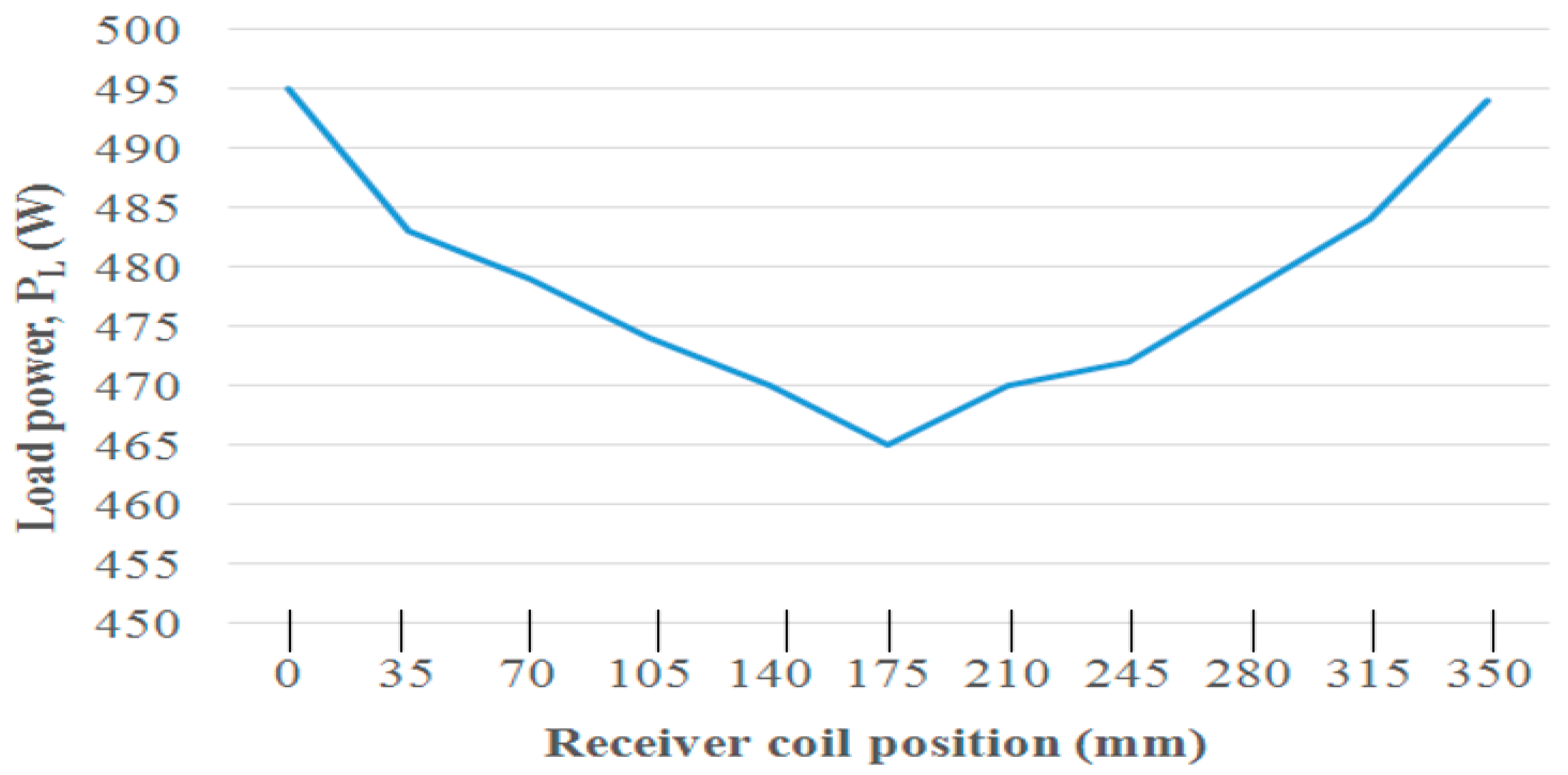
Figure 18.
Experimental laboratory setup of dynamic charging system of electric vehicles.


Table 1.
Design specifications of the proposed system.
| Design Specifications | Value |
|---|---|
| Resonant frequency | f = 80 kHz |
| Parameters of IPT transformer | n = 1, Ll1 = 165.9 µH, Ll2 = 82.05 µH, LM = 30.1 µH, k = 0.203 |
| Compensating inductor | Lf2 = 20 µH |
| Resonant capacitors | C1 = 23.86 nF, C2 = 48.24 nF, Cf2 = 329.27 nF |
| Load resistance | RL = 33–200 Ω |
| Load power | PL = 500 W |
| Air gap | h = 140 mm |
Table 2.
Comparison of different geometries with the proposed pad.
| Coil Topology | Evaluation Criteria | |||
|---|---|---|---|---|
| Overview | Flux Path Height | Polarization | Null Zones of Power Transfer with Horizontal Offset | |
| Circular |  | 1/4 of the pad diameter [30] | Not polarized | Occurs at about 38% of the pad diameter [23] |
| DD |  | 1/2 of the pad length [23,31] | Polarized | Creates at about 34% of the pad length [21] |
| DDQ |  | 2 times of circular with an extra single sided flux path [23] | Polarized | Occurs at about 77% of the pad length [32] |
| Bipolar |  | 2 times of circular | Polarized | Similar to DDQ [32] |
| Proposed |  | 1/2.5 of the pad length | Smaller sections are polarized | Not happens for extended DD transmitter |
© 2017 by the authors. Licensee MDPI, Basel, Switzerland. This article is an open access article distributed under the terms and conditions of the Creative Commons Attribution (CC BY) license (http://creativecommons.org/licenses/by/4.0/).
Share and Cite
MDPI and ACS Style
Alam, M.M.; Mekhilef, S.; Seyedmahmoudian, M.; Horan, B. Dynamic Charging of Electric Vehicle with Negligible Power Transfer Fluctuation. Energies 2017, 10, 701. https://doi.org/10.3390/en10050701
AMA Style
Alam MM, Mekhilef S, Seyedmahmoudian M, Horan B. Dynamic Charging of Electric Vehicle with Negligible Power Transfer Fluctuation. Energies. 2017; 10(5):701. https://doi.org/10.3390/en10050701
Chicago/Turabian StyleAlam, Md Morshed, Saad Mekhilef, Mehdi Seyedmahmoudian, and Ben Horan. 2017. "Dynamic Charging of Electric Vehicle with Negligible Power Transfer Fluctuation" Energies 10, no. 5: 701. https://doi.org/10.3390/en10050701
Note that from the first issue of 2016, this journal uses article numbers instead of page numbers. See further details here.