
Electromagnetic Performance Evaluation of an Outer-Rotor Flux-Switching Permanent Magnet Motor Based on Electrical-Thermal Two-Way Coupling Method


Abstract
:1. Introduction
2. Motor Topology and Design Equation
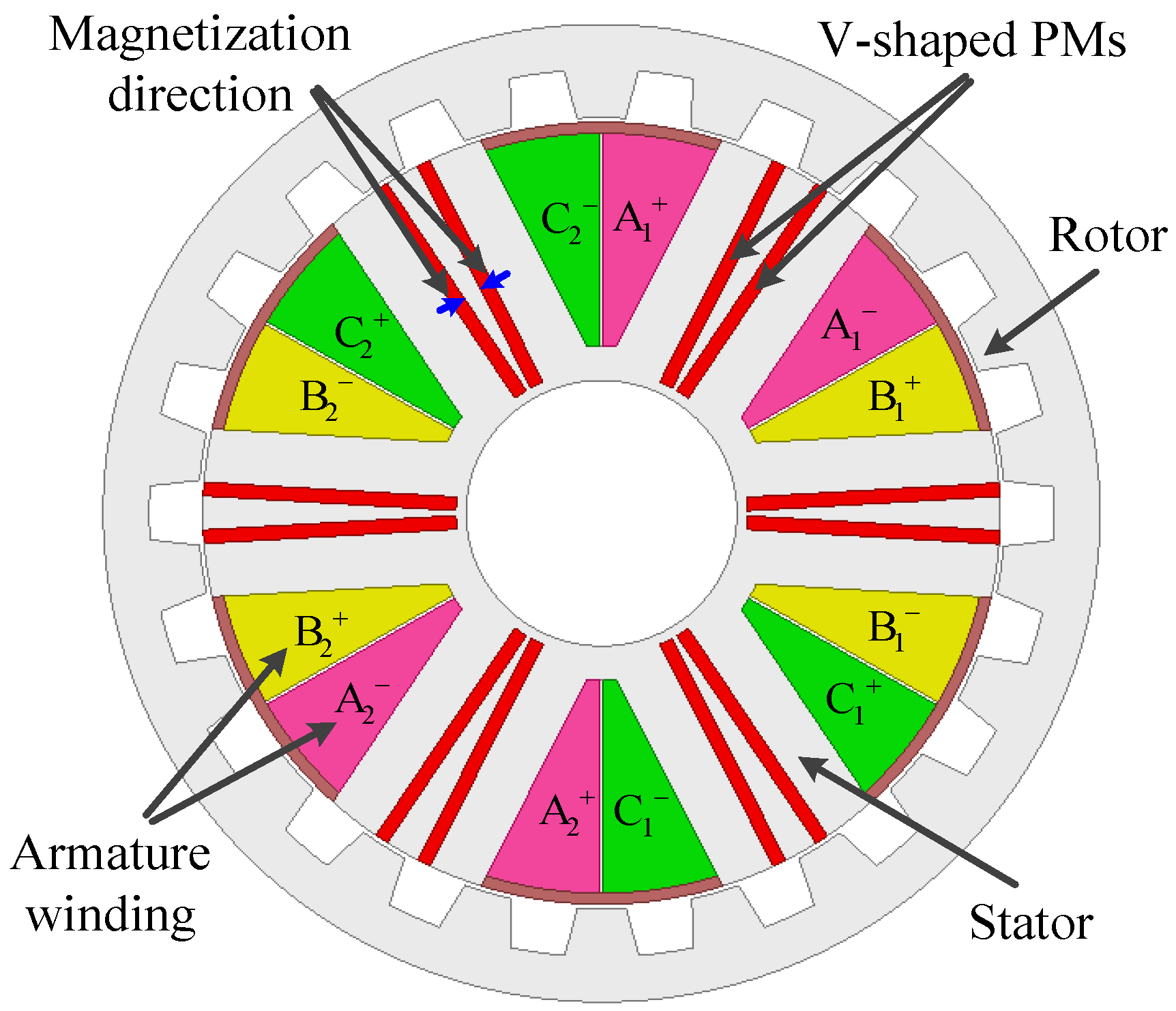
2.1. Motor Topology
2.2. Design Equations
3. Electrical-Thermal Two-Way Coupling Method
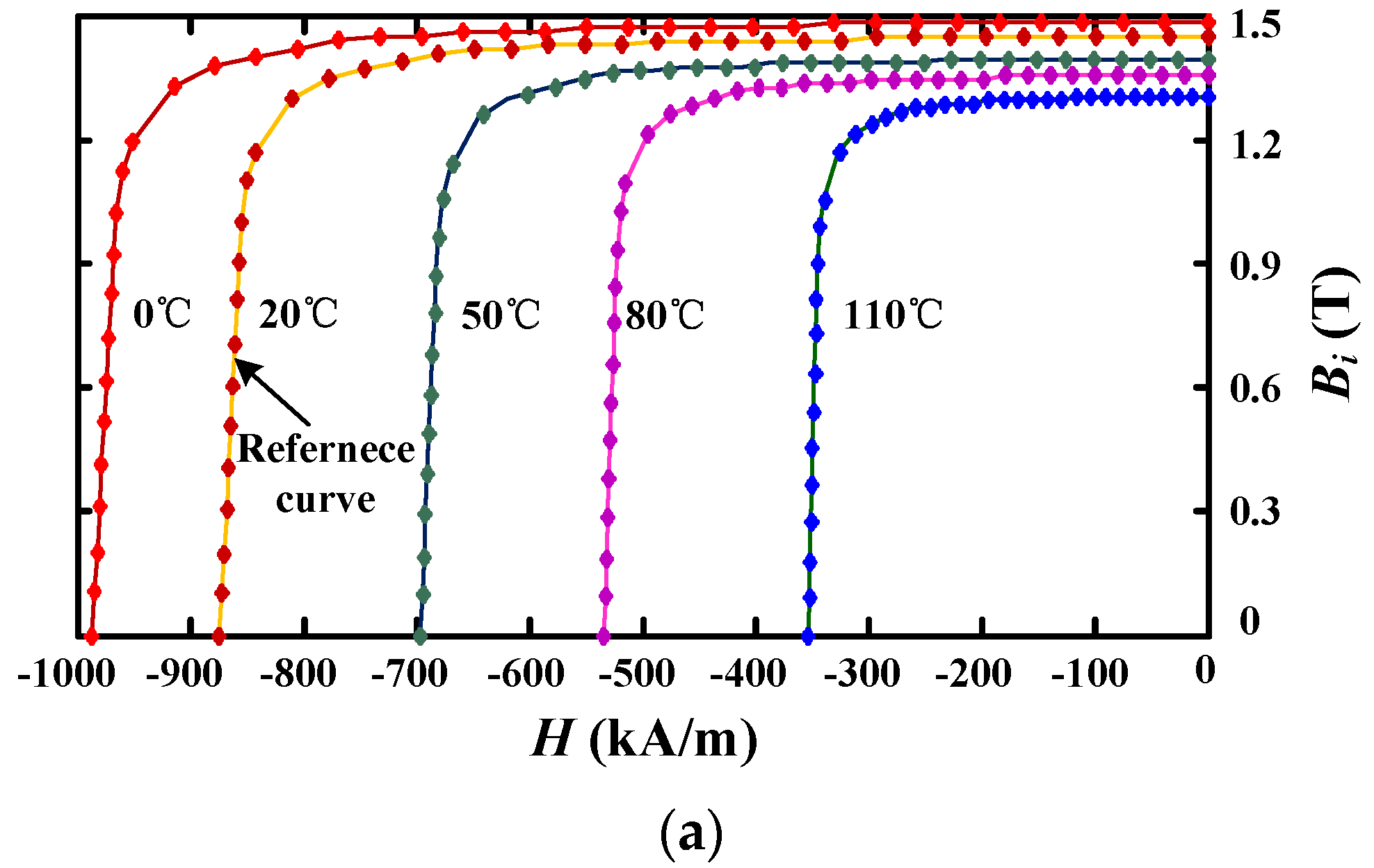
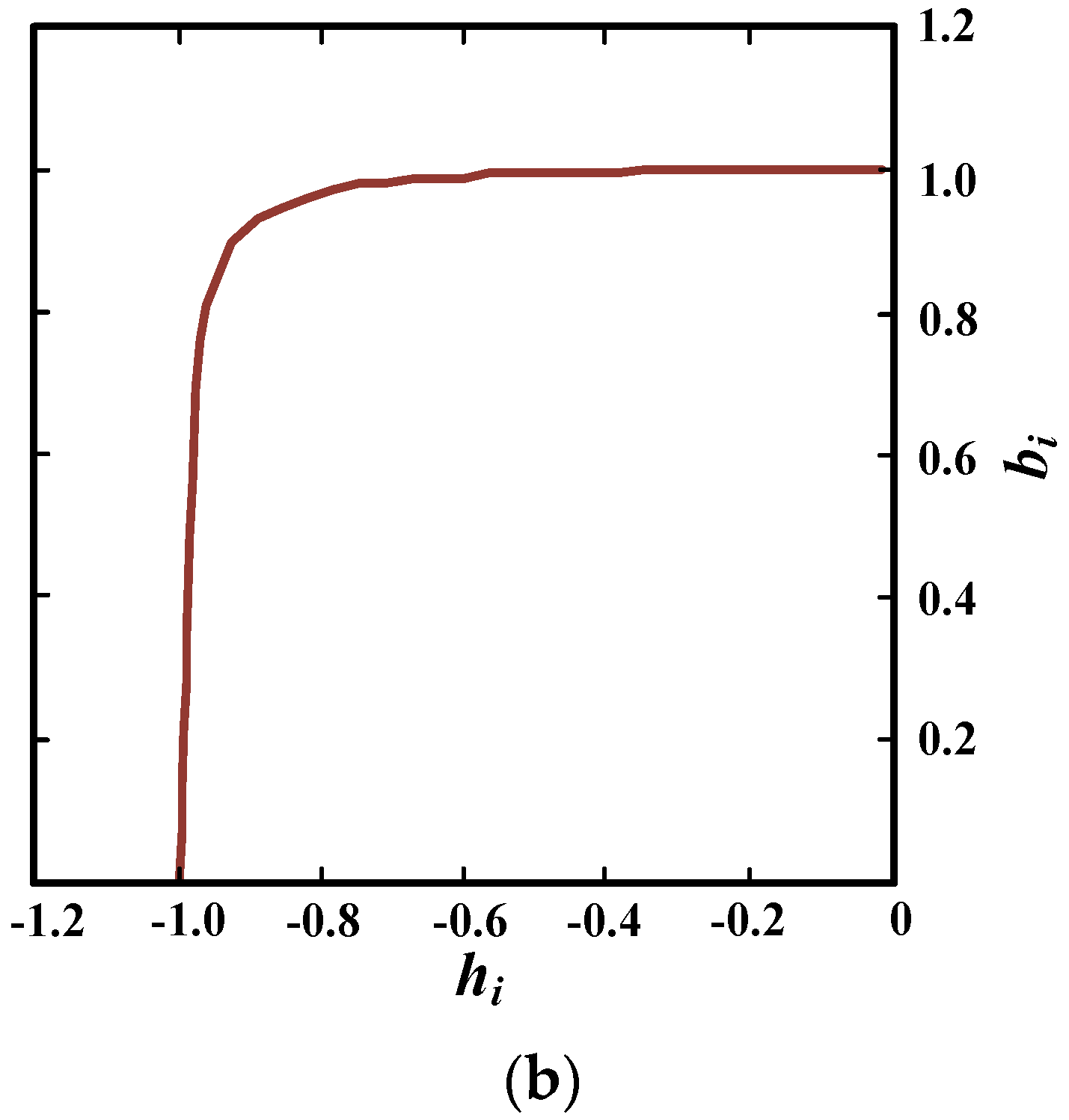
3.1. Characteristics of PM Material
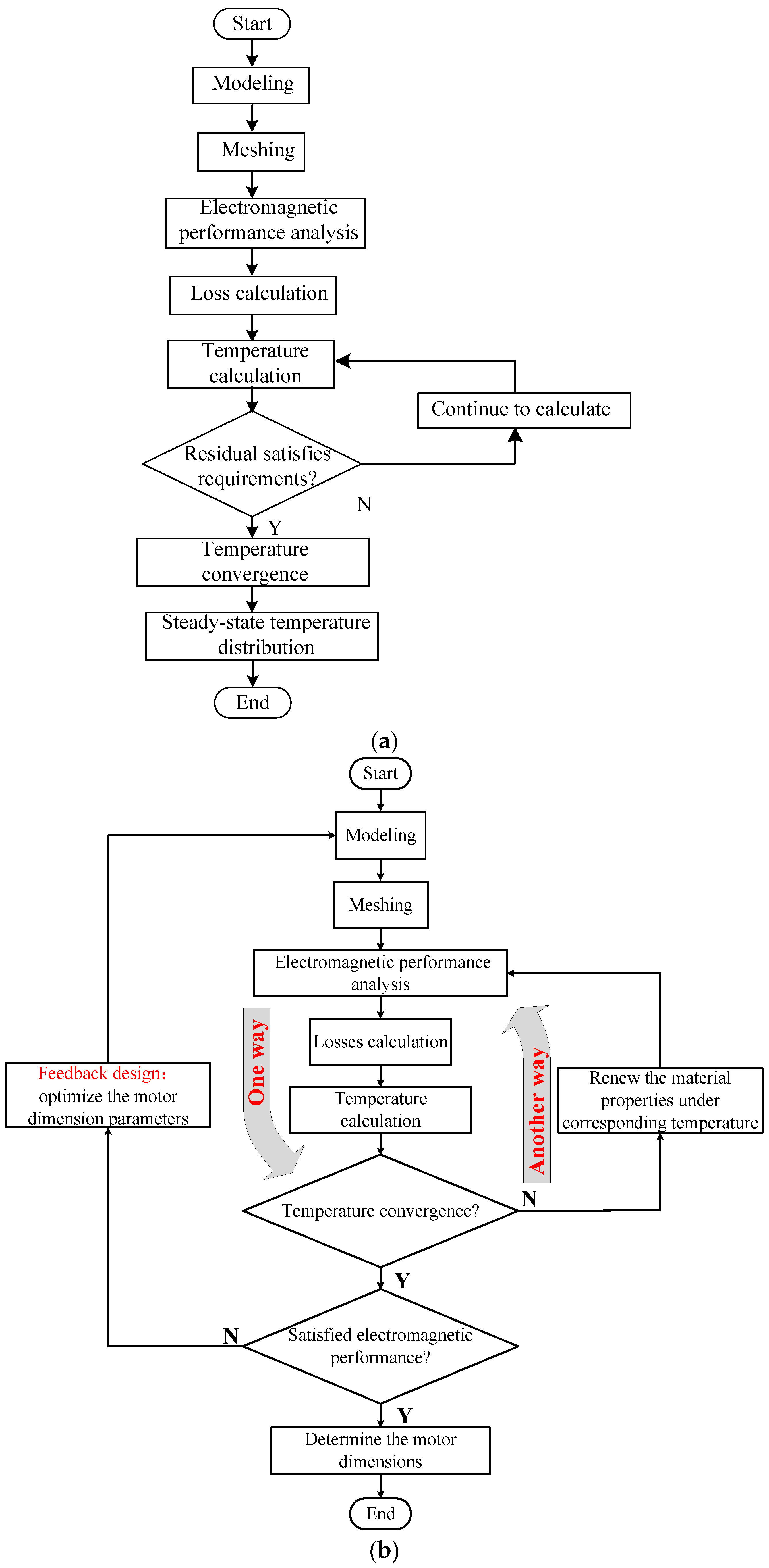
3.2. The Flow Chart of the Proposed Method
- Step 1
- Construct the 2D finite element analysis model and 3D thermal model according the motor configuration.
- Step 2
- The losses of each element are respectively calculated in the electromagnetic solver based on the demagnetization curve at the operating temperature. Then, the acquired losses used as the thermal source are imported into the thermal solver, and the temperature distribution can be obtained. Generally, the results between the obtained temperature and original operating temperature cannot achieve convergence. Because the original temperature is a reference temperature, it may not be the ideal temperature. The obtained temperature is relatively high after loss calculation. For example, as shown in Table 3, the temperature difference of the first time single-way coupling is 65.2 °C, which is far higher than temperature difference 0.8 °C by second time single-way coupling. Thus, the relatively large temperature difference can be generally considered no convergence.
- Step 3
- Alternatively, the temperature results are fed back to the electromagnetic solver by updating the material properties under the corresponding temperature. Then, the new loss results can be obtained by the electromagnetic performance analysis.
- Step 4
- Import the new loss results into the thermal solver to get the new temperature distribution. The temperature convergence can be estimated according to the two temperature results from the thermal solver. If the difference value of the two adjacent temperature results is within the setting threshold, the two-way coupling analysis is completed. Otherwise, return to step 3.
- Step 5
- Feed back to the design by optimizing the motor and evaluating the motor’s electromagnetic performances. After optimization, if the electromagnetic performances meet the required demands, the motor dimensions can be determined. Otherwise, the dimension parameters need to be further optimized.
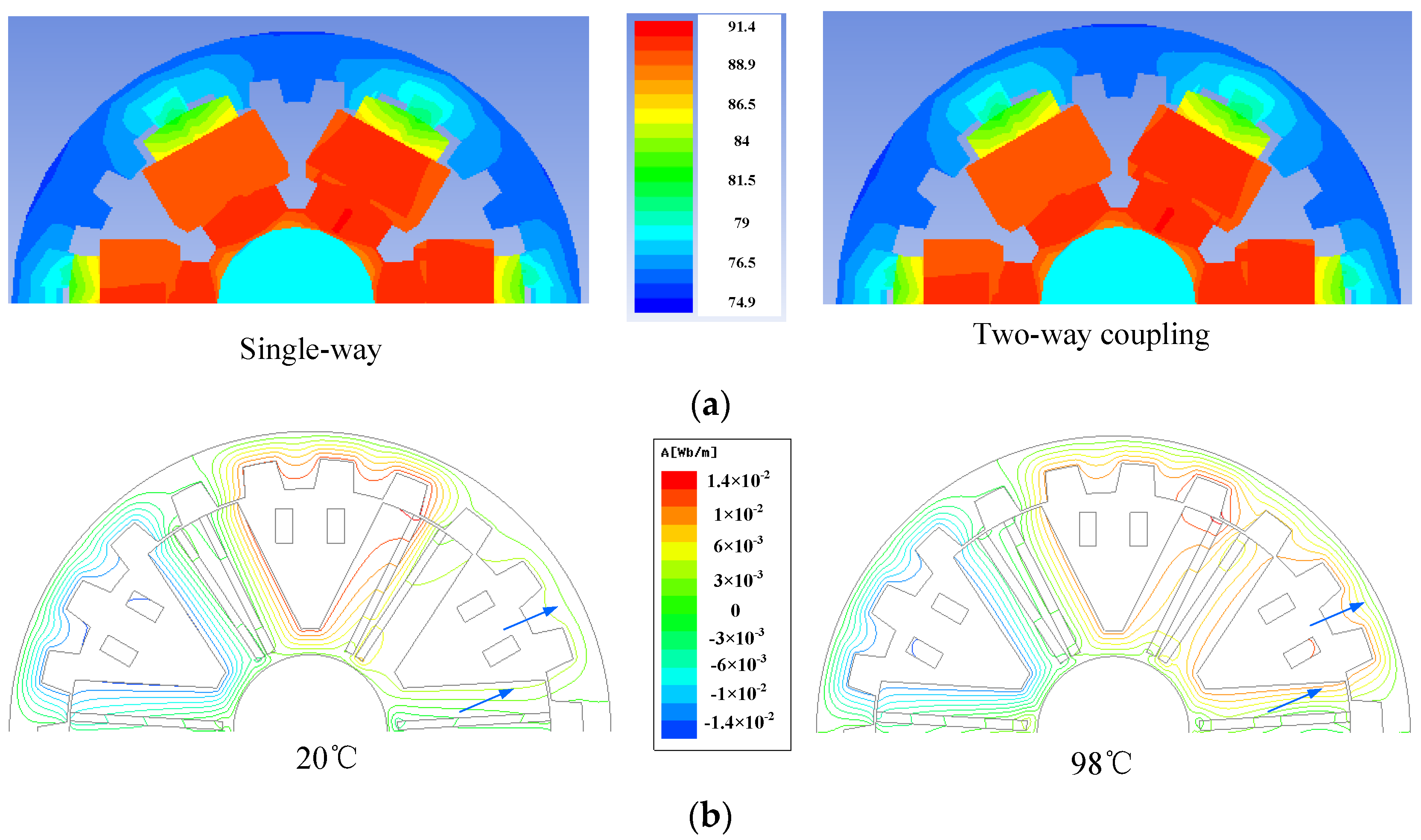
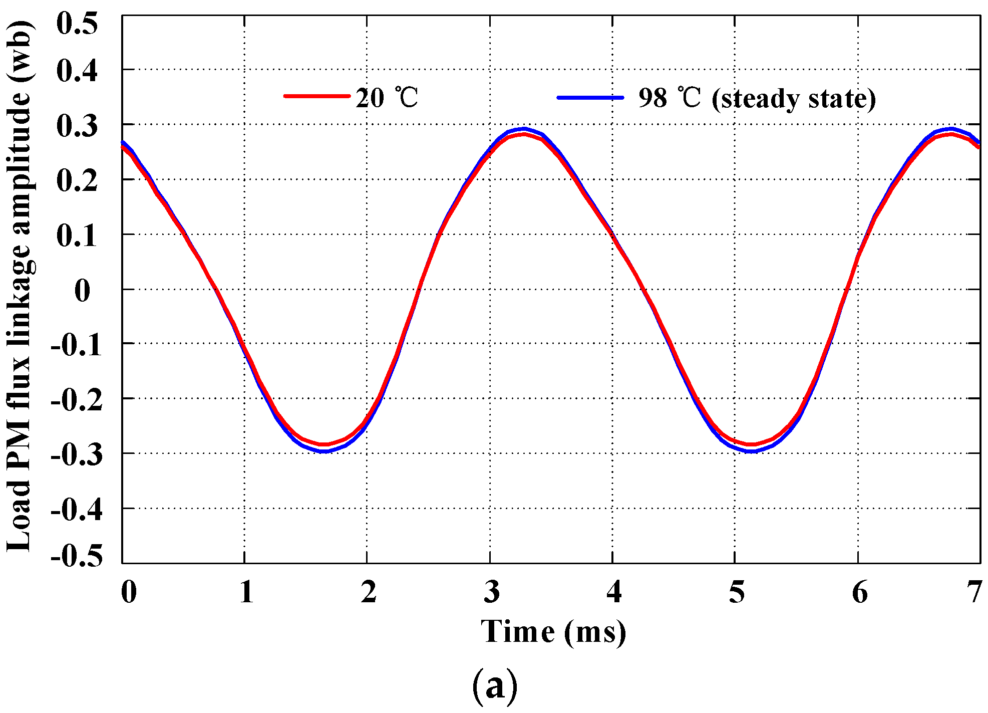
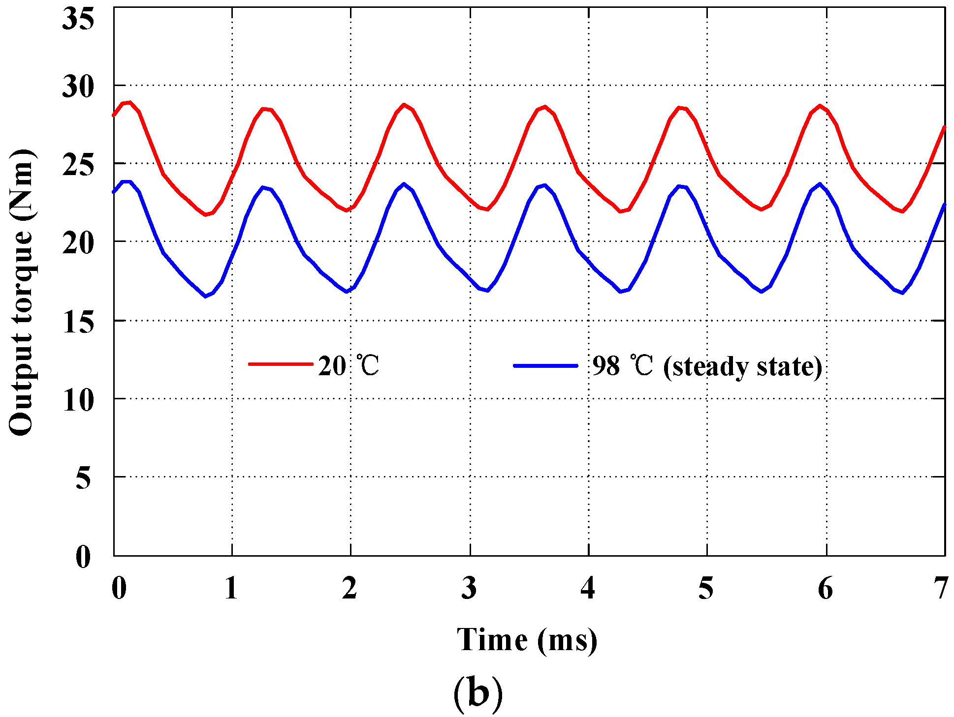
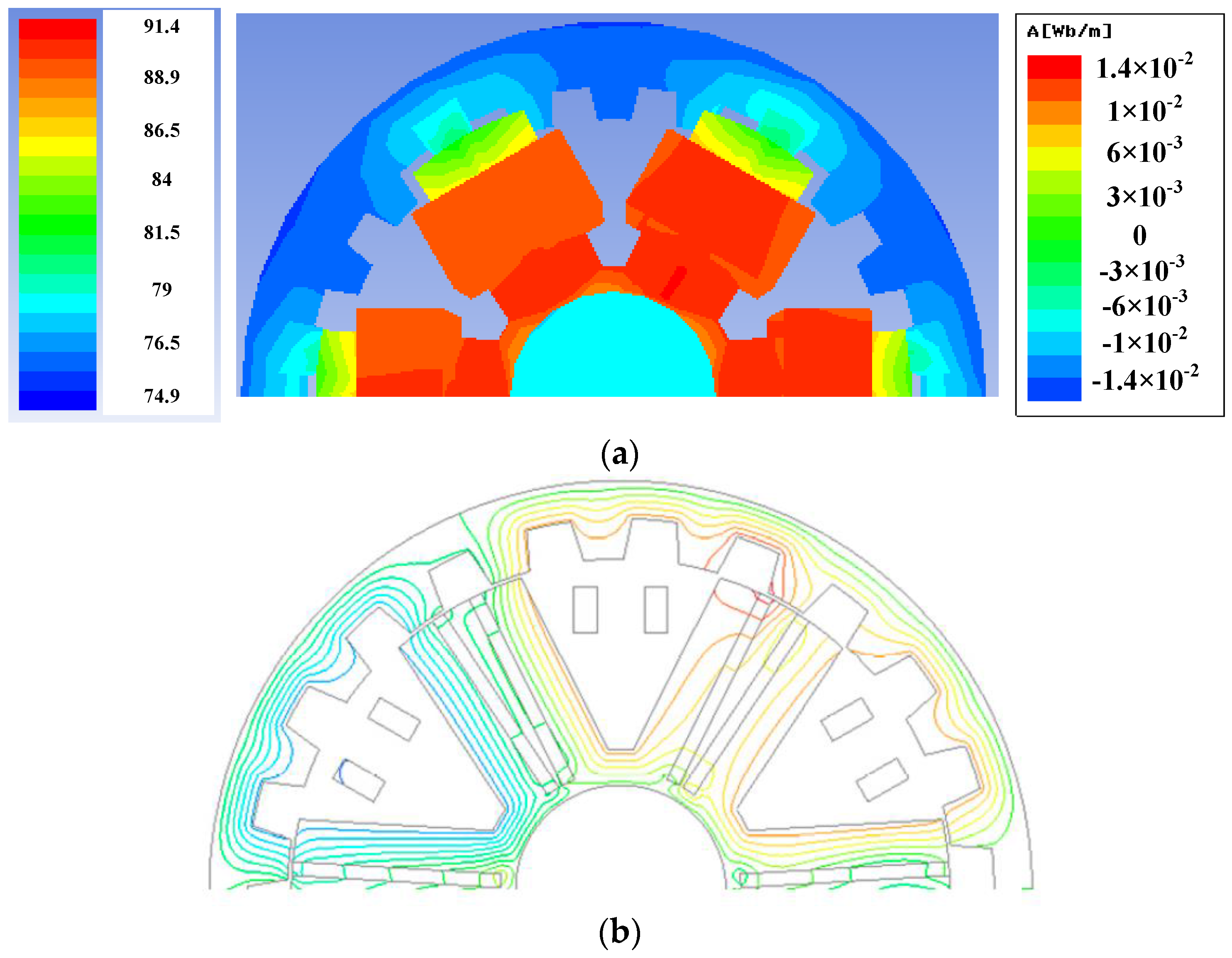
4. Electrical-Thermal Two-Way Coupling Analysis
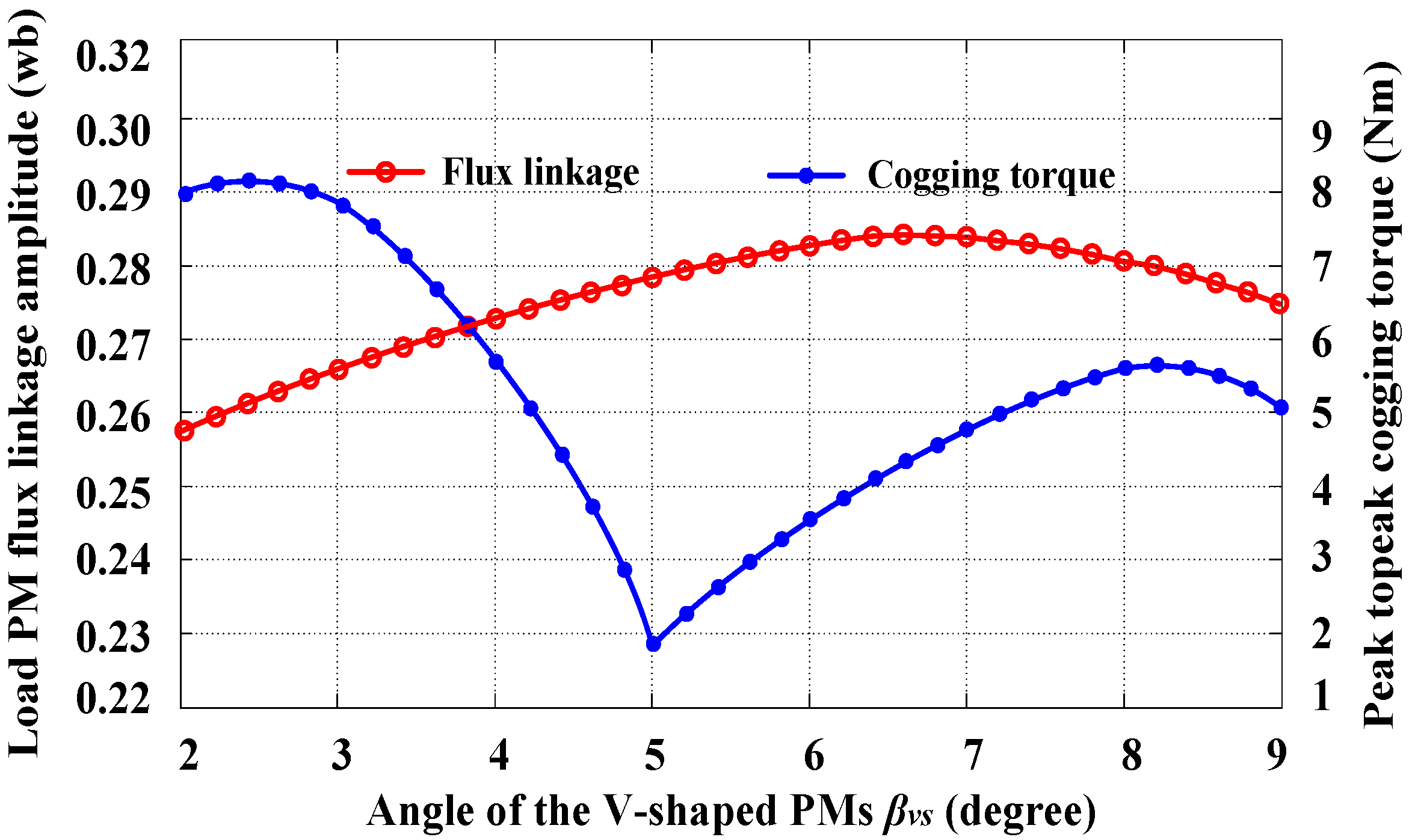
5. Motor Optimization
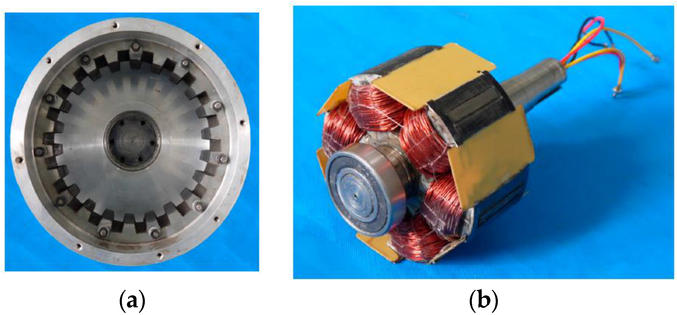
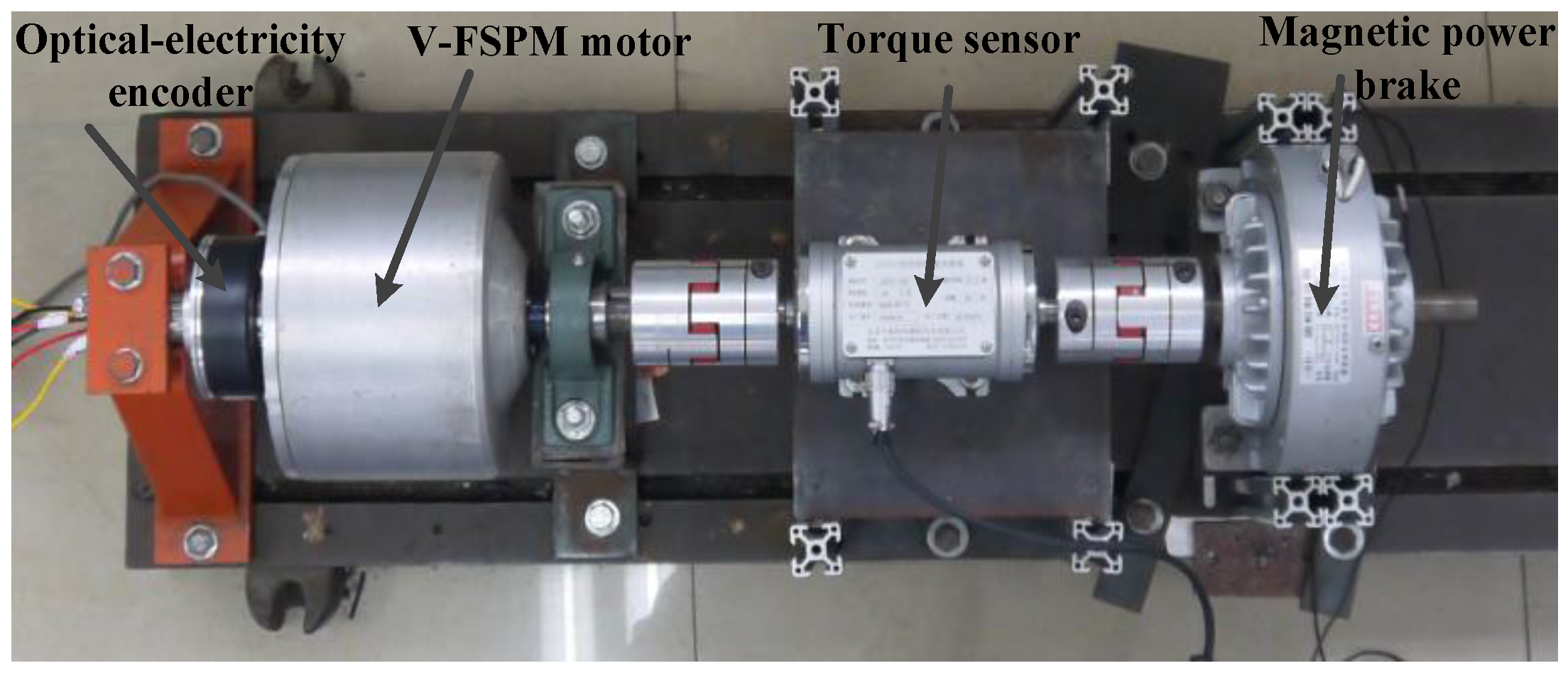
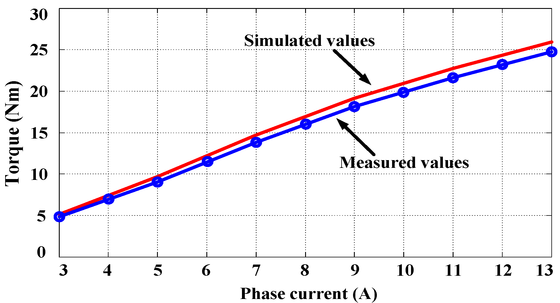
6. Experiment Validation
7. Conclusions
Acknowledgments
Author Contributions
Conflicts of Interest
References
- Chung, S.; Moon, S.; Kim, D.; Kim, J. Development of a 20-Pole–24-Slot SPMSM with Consequent Pole Rotor for In-Wheel Direct Drive. IEEE Trans. Ind. Electron. 2016, 63, 302–309. [Google Scholar] [CrossRef]
- Ifedi, C.J.; Mecrow, B.C.; Brockway, S.T.M.; Boast, G.S.; Atkinson, G.J.; Kostic-Perovic, D. Fault-Tolerant In-Wheel Motor Topologies for High-Performance Electric Vehicles. IEEE Trans. Ind. Appl. 2013, 49, 1249–1257. [Google Scholar] [CrossRef]
- Fei, W.Z.; Luk, P.C.K.; Shen, J.X.; Wang, Y.; Jin, M.J. A Novel Permanent-Magnet Flux Switching Machine with an Outer-Rotor Configuration for In-Wheel Light Traction Applications. IEEE Trans. Ind. Appl. 2012, 48, 1496–1506. [Google Scholar] [CrossRef]
- Xue, X.D.; Cheng, K.W.E.; Ng, T.W.; Cheung, N.C. Multi-Objective Optimization Design of In-Wheel Switched Reluctance Motors in Electric Vehicles. IEEE Trans. Ind. Electron. 2010, 57, 2980–2987. [Google Scholar] [CrossRef]
- Gu, W.W.; Zhu, X.Y.; Quan, L.; Du, Y. Design and optimization of permanent magnet brushless machines for electric vehicle applications. Energies 2015, 8, 13996–14008. [Google Scholar] [CrossRef]
- Zhu, X.Y.; Shu, Z.M.; Quan, L.; Xiang, Z.X.; Pan, X.Q. Multi-objective optimization of an outer-rotor V-shaped permanent magnet flux switching motor based on multi-level design method. IEEE Trans. Magn. 2016, 52, 1–8. [Google Scholar] [CrossRef]
- Yin, J.N.; Zhu, X.Y.; Quan, L.; Zhang, C.; Xiang, Z.X. Comprehensive multi-objective secularization optimization of a permanent magnet machine with correlation parameters stratified method. IET Electr. Power Appl. 2017, 11, 72–79. [Google Scholar] [CrossRef]
- Xiang, Z.X.; Zhu, X.Y.; Quan, L.; Du, Y.; Zhang, C.; Fan, D.Y. Multilevel Design Optimization and Operation of a Brushless Double Mechanical Port Flux-Switching Permanent-Magnet Motor. IEEE Trans. Ind. Electron. 2016, 63, 6042–6054. [Google Scholar] [CrossRef]
- Du, Y.; Yang, G.; Quan, L.; Zhu, X.Y.; Xiao, F.; Wu, H.Y. Detent Force Reduction of a C-Core Linear Flux-Switching Permanent Magnet Machine with Multiple Additional Teeth. Energies 2017, 10, 318. [Google Scholar] [CrossRef]
- Zhu, X.Y.; Xiang, Z.X.; Zhang, C.; Quan, L.; Du, Y.; Gu, W.W. Co-Reduction of Torque Ripple for Outer Rotor Flux-Switching PM Motor Using Systematic Multi-Level Design and Control Schemes. IEEE Trans. Ind. Electron. 2017, 64, 1102–1112. [Google Scholar] [CrossRef]
- Hua, W.; Cheng, M.; Zhu, Z.Q.; Howe, D. Analysis and optimization of back EMF waveform of a flux-switching permanent magnet motor. IEEE Trans. Energy Convers. 2008, 23, 727–733. [Google Scholar] [CrossRef]
- Raminosoa, T.; Gerada, C.; Galea, M. Design considerations for a fault-tolerant flux-switching permanent magnet machine. IEEE Trans. Ind. Electron. 2011, 58, 2818–2825. [Google Scholar] [CrossRef]
- Lin, T.C.; Zhu, Z.Q.; Liu, K.; Liu, J.M. Improved Sensorless Control of Switched-Flux Permanent-Magnet Synchronous Machines Based on Different Winding Configurations. IEEE Trans. Ind. Electron. 2016, 63, 123–132. [Google Scholar] [CrossRef]
- Zhu, Z.Q.; Chen, J.T.; Pang, Y.; Howe, D.; Iwasaki, S.; Deodhar, R. Analysis of a Novel Multi-Tooth Flux-Switching PM Brushless AC Machine for High Torque Direct-Drive Applications. IEEE Trans. Magn. 2008, 44, 4313–4316. [Google Scholar] [CrossRef]
- Zhang, G.; Hua, W.; Cheng, M.; Liao, J.G.; Wang, K.; Zhang, J.Z. Investigation of an Improved Hybrid-Excitation Flux-Switching Brushless Machine for HEV/EV Applications. IEEE Trans. Ind. Appl. 2015, 51, 3791–3799. [Google Scholar] [CrossRef]
- Li, G.G.; Ojeda, J.; Hoang, E.; Gabsi, M.; Lécrivain, M. Thermal–Electromagnetic Analysis for Driving Cycles of Embedded Flux-Switching Permanent-Magnet Motors. IEEE Trans. Veh. Technol. 2012, 61, 140–151. [Google Scholar] [CrossRef]
- Chen, Y.Y.; Zhu, X.Y.; Quan, L.; Wang, L. Performance Analysis of a Double-Salient Permanent-Magnet Double-Rotor Motor Using Electromagnetic–Thermal Coupling Method. IEEE Trans. Appl. Supercond. 2016, 26, 5205305. [Google Scholar] [CrossRef]
- Li, G.J.; Ojeda, J.; Hoang, E.; Gabsi, M. Thermal-electromagnetic analysis of a fault-tolerant dual-star flux-switching permanent magnet motor for critical applications. IET Electr. Power Appl. 2011, 5, 503–513. [Google Scholar] [CrossRef]
- Sun, X.K.; Cheng, M.; Zhu, S.; Zhang, J.Z. Coupled Electromagnetic-Thermal-Mechanical Analysis for Accurate Prediction of Dual-Mechanical-Port Machine Performance. IEEE Trans. Ind. Appl. 2012, 48, 2240–2248. [Google Scholar] [CrossRef]
- Thomas, A.S.; Zhu, Z.Q.; Li, G.J. Thermal Modelling of Switched Flux Permanent Magnet Machines. In Proceedings of the 2014 International Conference on Electrical Machines, Berlin, Germany, 2–5 September 2014; pp. 2212–2217. [Google Scholar]
- Cai, X.H.; Cheng, M.; Zhu, S.; Zhang, J.W. Thermal Modeling of Flux-Switching Permanent-Magnet Machines Considering Anisotropic Conductivity and Thermal Contact Resistance. IEEE Trans. Ind. Electron. 2016, 63, 3355–3365. [Google Scholar] [CrossRef]
- Cao, R.W.; Mi, C.; Cheng, M. Quantitative Comparison of Flux-Switching Permanent-Magnet Motors With Interior Permanent Magnet Motor for EV, HEV, and PHEV Applications. IEEE Trans. Magn. 2012, 48, 2374–2384. [Google Scholar] [CrossRef]
- Zhang, Y.J.; Ruan, J.J.; Huang, T.; Yang, X.P.; Zhu, H.Q.; Yang, G. Calculation of temperature rise in air-cooled induction motors through 3-D coupled electromagnetic fluid-dynamical and thermal finite-element analysis. IEEE Trans. Magn. 2012, 48, 1047–1050. [Google Scholar] [CrossRef]
- Zhou, P.; Lin, D.; Xiao, Y. Temperature-dependent Demagnetization Model of Permanent Magnets for Finite Element Analysis. IEEE Trans. Magn. 2012, 48, 1031–1034. [Google Scholar] [CrossRef]
- Zhou, Y.J.; Zhu, Z.Q. Torque Density and Magnet Usage Efficiency Enhancement of Sandwiched Switched Flux Permanent Magnet Machines Using V-Shaped Magnets. IEEE Trans. Magn. 2013, 49, 3834–3837. [Google Scholar] [CrossRef]


| Symbols | Descriptions |
|---|---|
| Dso | Stator outer diameter |
| la | Stack length of the motor |
| ks | Chute coefficient, which is the cosine relation between the rotor chute angle and the stator tooth distance |
| kd | Magnetic flux leakage coefficient, which is the ratio of the effective flux in the turns of the winding to the air gap flux |
| ksio | The ratio of inside diameter and outside diameter of the stator |
| As | Line load of the armature windings |
| Bgmax | The peak air gap flux density at no-load condition |
| cs | The pole arc coefficient of stator tooth, which is the ratio of stator tooth pole arc width to stator pole pitch |
| η | Efficiency, which is the ratio of the output power to the input power |
| Tref | The reference temperature |
| Qout(Tref) | The output torque at the reference temperature |
| Number | H | Bi | Number | H | Bi | Number | H | Bi |
|---|---|---|---|---|---|---|---|---|
| 1 | −874,891 | 0 | 14 | −810,209 | 1.29581 | 27 | −389,779 | 1.440634 |
| 2 | −872,185 | 0.104417 | 15 | −777,868 | 1.3465 | 28 | −357,438 | 1.442663 |
| 3 | −870,323 | 0.196823 | 16 | −745,528 | 1.373112 | 29 | −325,098 | 1.444691 |
| 4 | −868,294 | 0.305071 | 17 | −713,187 | 1.392021 | 30 | −292,757 | 1.445884 |
| 5 | −866,591 | 0.405398 | 18 | −680,846 | 1.40616 | 31 | −260,416 | 1.446921 |
| 6 | −864,729 | 0.505725 | 19 | −648,505 | 1.415546 | 32 | −228,075 | 1.447947 |
| 7 | −862,867 | 0.603412 | 20 | −616,164 | 1.422242 | 33 | −195,734 | 1.448959 |
| 8 | −861,004 | 0.703739 | 21 | −583,824 | 1.426483 | 34 | −163,394 | 1.44997 |
| 9 | −859,142 | 0.811986 | 22 | −551,483 | 1.430411 | 35 | −131,053 | 1.450959 |
| 10 | −857,272 | 0.904392 | 23 | −519,142 | 1.43348 | 36 | −98,712.1 | 1.451946 |
| 11 | −855,410 | 1.00472 | 24 | −486,801 | 1.43655 | 37 | −66,371.3 | 1.4524 |
| 12 | −849,824 | 1.09976 | 25 | −454,461 | 1.438146 | 38 | −34,030.5 | 1.45242 |
| 13 | −842,550 | 1.174 | 26 | −422,120 | 1.43921 | 39 | 0 | 1.45244 |
| Analysis Method | Iteration Times | |||||||
|---|---|---|---|---|---|---|---|---|
| 0 | 10 | 20 | 30 | 40 | 50 | …… | ||
| Single-way | Temperature (°C) | 20 | 85.2 | 86 | 86 | 86 | 86 | 86 |
| Temperature difference (°C) | − | 65.2 | 0.8 | 0 | 0 | 0 | 0 | |
| Two-way coupling | Temperature (°C) | 20 | 86 | 102 | 97.3 | 98 | 98 | 98 |
| Temperature difference (°C) | − | 66 | 16 | 4.7 | 0.7 | 0 | 0 | |
| Material | Density [kg·m−3] | Specific Heat [J/(kg °C)] | Thermal Conductivity [W/(m °C)] |
|---|---|---|---|
| Copper | 8978 | 381 | 387.6 |
| NdFeB | 7500 | 450 | 9 |
| Silicon Steel | 7872 | 426 | 40 |
| Insulation | 1300 | 1400 | 0.3 |
| Aluminum | 2719 | 871 | 202.4 |
| Parameters | Values | Unit |
|---|---|---|
| Rotor pole arc width | 6 | degree |
| Rotor teeth height | 8 | mm |
| Rotor teeth arc width at yoke | 10 | degree |
| Air gap length | 0.8 | mm |
| Placed angle of the two PMs | 5 | degree |
| PM arc width | 2 | degree |
| Stator yoke radius | 30 | mm |
| Stator yoke arc width | 10 | degree |
| Stator inner radius | 22.4 | mm |
| Parameters | Unit | Initial Value | Final Value | |
|---|---|---|---|---|
| PM arc width | deg | 3 | 2 | |
| Placed angle of the two PMs | deg | 5.5 | 5 | |
| Rotor pole arc width | deg | 8 | 6 | |
| Air gap length | mm | 0.6 | 0.8 | |
| Stator yoke arc width | deg | 9 | 10 | |
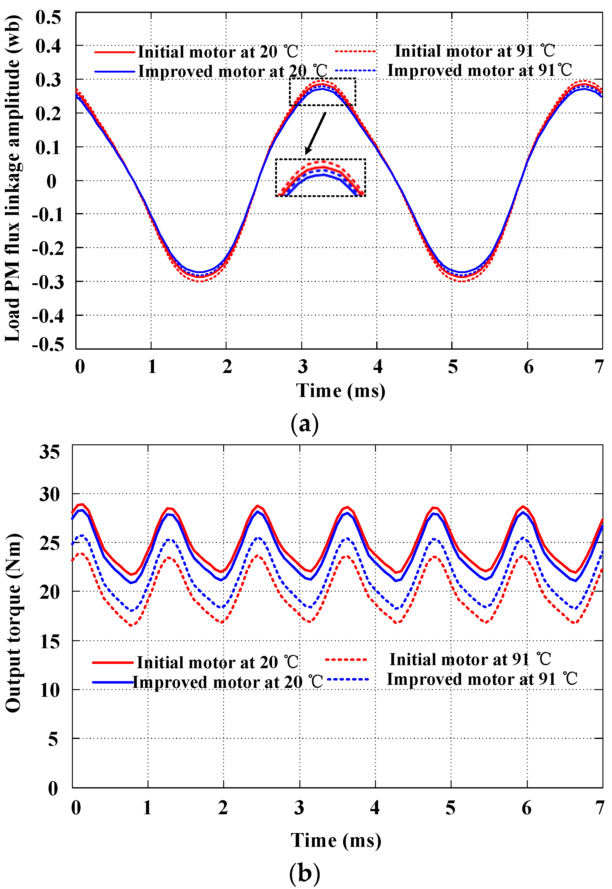
| Results | Initial motor at 20 °C | Initial motor at 91 °C | Improved motor at 20 °C | Improved motor at 91 °C |
| Output torque (Nm) | 26.21 | 20.18 | 25.49 | 22.35 |
| Ktemp | - | 0.79 | - | 0.88 |
© 2017 by the authors. Licensee MDPI, Basel, Switzerland. This article is an open access article distributed under the terms and conditions of the Creative Commons Attribution (CC BY) license (http://creativecommons.org/licenses/by/4.0/).
Share and Cite
Shu, Z.; Zhu, X.; Quan, L.; Du, Y.; Liu, C. Electromagnetic Performance Evaluation of an Outer-Rotor Flux-Switching Permanent Magnet Motor Based on Electrical-Thermal Two-Way Coupling Method. Energies 2017, 10, 677. https://doi.org/10.3390/en10050677
Shu Z, Zhu X, Quan L, Du Y, Liu C. Electromagnetic Performance Evaluation of an Outer-Rotor Flux-Switching Permanent Magnet Motor Based on Electrical-Thermal Two-Way Coupling Method. Energies. 2017; 10(5):677. https://doi.org/10.3390/en10050677
Chicago/Turabian StyleShu, Zhengming, Xiaoyong Zhu, Li Quan, Yi Du, and Chang Liu. 2017. "Electromagnetic Performance Evaluation of an Outer-Rotor Flux-Switching Permanent Magnet Motor Based on Electrical-Thermal Two-Way Coupling Method" Energies 10, no. 5: 677. https://doi.org/10.3390/en10050677
APA StyleShu, Z., Zhu, X., Quan, L., Du, Y., & Liu, C. (2017). Electromagnetic Performance Evaluation of an Outer-Rotor Flux-Switching Permanent Magnet Motor Based on Electrical-Thermal Two-Way Coupling Method. Energies, 10(5), 677. https://doi.org/10.3390/en10050677