Article

Fast Calculation Model and Theoretical Analysis of Rotor Unbalanced Magnetic Pull for Inter-Turn Short Circuit of Field Windings of Non-Salient Pole Generators

School of Electrical Engineering, Beijing Jiaotong University, Beijing 100044, China
*
Author to whom correspondence should be addressed.
Energies 2017, 10(5), 732; https://doi.org/10.3390/en10050732
Submission received: 27 March 2017 / Revised: 14 May 2017 / Accepted: 16 May 2017 / Published: 20 May 2017

Abstract

:
Inter-turn short circuit of field windings (ISCFW) may cause the field current of a generator to increase, output reactive power to decrease, and unit vibration to intensify, seriously affecting its safe and stable operation. Full integration of mechanical and electrical characteristics can improve the sensitivity of online monitoring, and detect the early embryonic period fault of small turns. This paper studies the calculations and variations of unbalanced magnetic pull (UMP), of which the excitation source of rotor vibration is the basis and key to online fault monitoring. In grid load operation, ISCFW are first calculated with the multi-loop method, so as to obtain the numerical solutions of the stator and the rotor currents during the fault. Next, the air-gap magnetic field of the ISCFW is analyzed according to the actual composition modes of the motor loops in the fault, so as to obtain the analytic expressions of the air-gap magnetic motive force (MMF) and magnetic density. The UMP of the rotor is obtained by solving the integral of the Maxwell stress. The correctness of the electric quantity calculation is verified by the ISCFW experiment, conducted in a one pair-pole non-salient pole model machine. On this basis, comparing the simulation analysis with the calculation results of the model in this paper not only verifies the accuracy of the electromagnetic force calculation, but also proves that the latter has the advantages of a short time consumption and high efficiency. Finally, the influencing factors and variation law of UMP are analyzed by means of an analytic model. This develops a base for the online monitoring of ISCFW with the integration of mechanical and electrical information.

1. Introduction

The requirements for the safe and stable operation of synchronous generators continually increase with the continuous development of power systems. Inter-turn short circuit of field windings (ISCFW) is a common electrical fault in generators. A small turns short circuit fault may not affect the normal operation of generators [1,2]. A spreading fault will cause the field current of the generator to increase, output reactive power to reduce, and unit vibration to intensify. This causes burning of shaft necks and bearings, seriously threatening the safe and stable operation of the generator unit and the power system [3,4].
The traditional method of monitoring the ISCFW is to use the electrical quantity in the fault to achieve fault monitoring [5]. Although most of these methods are mature, there are still many problems, such as the need to rely on branch current transformers (the vast majority of turbines cannot be installed), lower sensitivity, and larger monitoring dead zones. As a result, domestic and foreign scholars are looking for new monitoring methods.
In the motor, owing to mechanical and electrical coupling, the ISCFW will cause partial magnetic poles to short circuit, thereby causing air gap magnetic field distortion. This produces the air gap electromagnetic force wave and unbalanced magnetic pull (UMP) differing from normal operation, causing the radial vibration of the motor rotors. Many domestic and foreign scholars have tried to use the vibration characteristics of the generator to monitor the fault. Trutt proved that unit bearing vibration and shaft vibration would exceed the normal standard when the ISCFW occurred [6]. The increase of vibration amplitude and field current, and the decrease of output reactive power were tending toward uniformity [7,8]. The calculation model for fault electromagnetic torque was established based on the multi-loop and finite element methods. The correctness of the model was verified experimentally, and the harmonic characteristics of the steady-state electromagnetic torque in the fault were analyzed in the literature [4,9]. The electromagnetic forces on the motor eccentric fault were calculated using a numerical method from the literature [10,11], and the obtained results confirm the experimental results.
A great deal of research has been achieved in the literature [12,13]. The vibration equations of stator and rotor were derived, and the vibration characteristics of the stator and rotor after faults were determined [14,15]. From this, we can see that it is feasible to use the vibration characteristics of the generator rotor as an auxiliary fault criterion. However, most of the existing studies focused on the vibration response of the rotor in the fault, and studies on vibration excitation sources remain insufficient and are not detailed. UMP is the excitation source of rotor vibration in the fault, and its numerical size is closely related to the severity of the fault and the running state of the generator. The accurate calculation of UMP in a fault, the variation law, and the influencing factors are the basis and key to detecting ISCFW using rotor vibration characteristics.
Aiming at the common one-pair pole turbo generator, this paper puts forward a method to obtain the UMP on a rotor by analytic calculation of the air gap magnetic field in ISCFW. First of all, the ISCFW of the turbo generator in the grid connection operation are calculated using the multi-loop method, and the numerical solutions of the stator and the rotor currents on the faults are obtained. A fault experiment on the model machine is conducted, and the experimental results are compared with theoretical calculation results. On this basis, the analytic calculations of air gap magnetic motive force (MMF) and magnetic density on inter-turn short circuit faults are conducted; the size and direction of the UMP on the rotor in faults are calculated using the Maxwell stress tensor method, and the analytic calculation models of the UMP are obtained. Then, in order to solve the problem that UMP cannot be measured directly by experiment, finite element calculations of UMP are conducted by means of the finite element physical generator model established with ANSYS simulation software. The correctness of the rapid calculation model is verified by comparing the finite element calculation and analytic model calculation results. Finally, the influences of the short position, number of turns, and the running state on the rotor UMP in the generator rotor inter-turn short circuit faults are studied. The variation law of UMP is obtained by means of the rapid calculation model. The conclusion not only provides the theoretical basis for the further study of rotor vibration response characteristics, but also lays the foundation for the online monitoring of rotor inter-turn short circuits with mechanical and electrical information integration.

2. Fast Calculation Model of UMP

The accurate calculation of the UMP in the fault is the basis of the study on the rotor vibration excitation source. Because the UMP of the rotor cannot be directly measured experimentally, obtaining of the UMP is achieved by finite element simulation. Although this method can fully consider the saturation of the magnetic field, the internal magnetic field distribution of the motor is set closer to the actual situation so that the final simulation results error is small. The biggest drawback of this method is that its calculation process is too time-consuming. For a real generator, the higher the number of winding coils, the slower the calculation will be. This is difficult to accept in engineering. The rapid calculation model of UMP based on the multi-loop method proposed in this paper can take into account both accuracy and calculation speed.

2.1. Loop Currents in Rotor Inter-Turn Short Circuit Faults

The basic thinking of calculating ISCFW with the multi-loop method is as follows: First, the inductive parameters of coils are obtained by taking a single coil as a research object. Next, in accordance with the actual winding connection and composition mode in the faults, the winding loop parameters are calculated through the related coil parameters [16,17]. This method involves the stator phase and rotor winding, and calculates current and voltage of all branches of the stator and field windings, along with the damp circuit [18].
Under the premise of field winding, the circuit topology structure changes. Unbalanced current inside the stator phase winding from the fault is considered, and the equation is stated with all loop currents (with the stator and the rotor as variables) and is obtained based on the multi-loop theory [19]:
( M ' + M T ) D I ' + ( D M ' + R ' + R T ) I ' = E
where M ' and R ' are a loop inductance matrix and a loop resistance matrix, respectively. The value of M ' as a time-varying matrix varies with the relative motion between the stator and the rotor. The values of M T and R T as constant matrices are related to the grid line parameters, the transformer resistance, leakage inductance, the internal resistance, and the internal inductance of the field system. Column vector I ' is the current in each circuit of the stator and rotor, including the normal circuit and the fault additional circuit of the rotor field winding, the damp circuit, and the stator armature winding circuit. Column vector E, as a known quantity, is composed of the grid voltage and the power supply voltage of the field system. D is a differential operator, d / d t . Equation (1) is the multi-loop mathematical model of the synchronous generator on field winding inter-turn short circuit faults. The numerical solutions of the current and the voltage of the stator and the rotor on the faults can be obtained by means of an appropriate numerical solving method, so as to realize the transient simulation of the faults. The analyses and calculations below are based on the results of this model.

2.2. Air Gap MMF and Magnetic Density in Rotor Inter-Turn Short Circuit Fault

2.2.1. Air Gap MMF Generated by Rotor Field Current

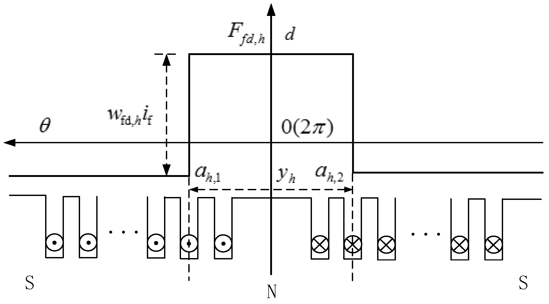
The field winding of each pole of the non-salient pole synchronous generator is composed of distributed concentric coils with different pitches in series. Let the starting point of the rotor spatial coordinate θ be the d-axis of the rotor. The MMF alone produced by each concentric coil is a rectangular wave symmetrical with the d-axis center line, and distributed around the whole motor air gap, as shown in Figure 1.
The expression of the air gap MMF F fd , h generated by the hth (h = 1, 2, 3, …) concentric coil in the field winding is:
F fd , h ( θ ) = { 2 π y h 2 π w fd , h i f , 0 θ < α h , 1 or α h , 2 θ < 2 π y h 2 π w fd , h i f , α h , 1 θ < α h , 2
where y h and w fd , h are, respectively, the pitch and turn number of the hth concentric coil. α h , 1 and α h , 2 are the rotor coordinate electric angles corresponding to its two edges.
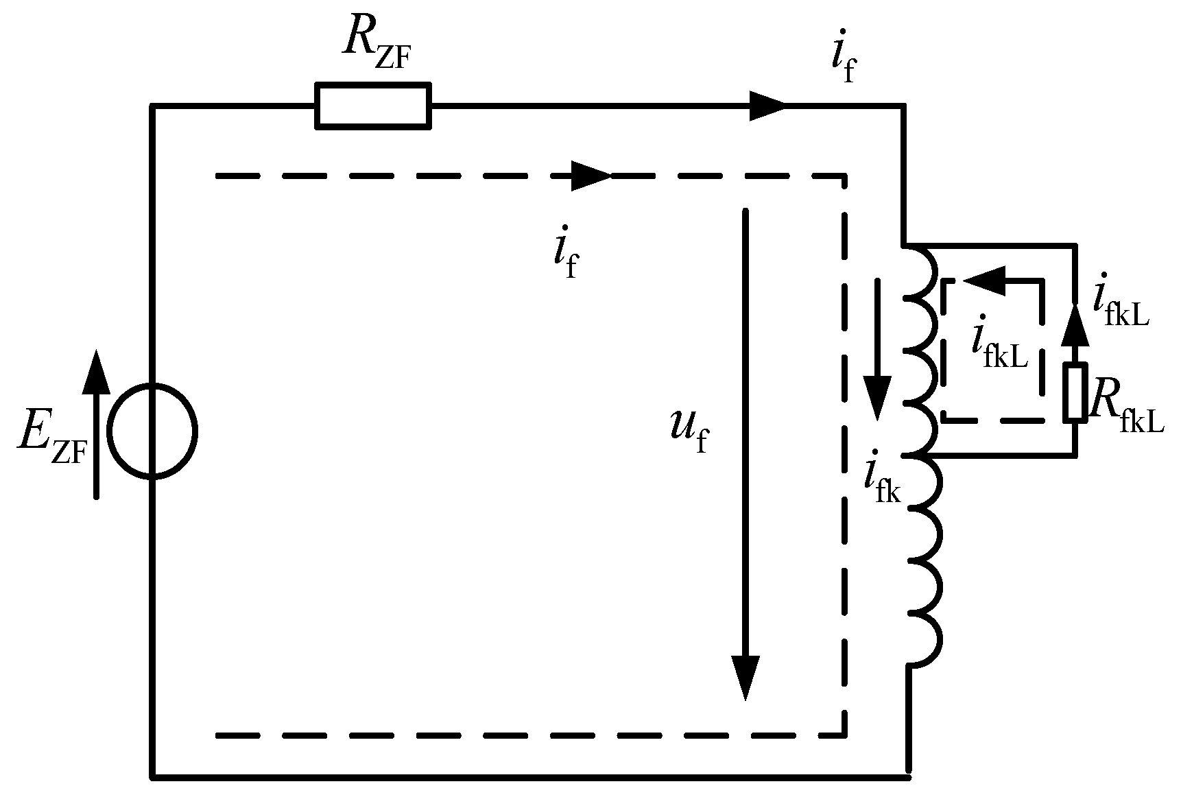
On field winding inter-turn short circuits with a synchronous generator, the field winding is divided into a normal field circuit (with current if) and the field fault additional circuit (with current ifkL), as shown in Figure 2.
In Figure 2, EZF is electromotive force, RfkL is the short-circuit transition resistance, and RZF is internal resistance of the field power supply. In the rotor inter-turn short circuit faults, in addition to the DC component, there is an AC component in the field current. The AC component is small, so its influences on the air gap magnetic field are not considered here. MMF F fd , h f in the air gap—generated by the fault winding—is equivalent to the superposition of the MMF generated by the normal field circuit and reverse MMF generated by the fault additional circuit, as shown in Equation (3):
F fd , h f ( θ ) = F fd , n , h f ( θ ) + F fd , f , h f ( θ )
where F fd , n , h f and F fd , f , h f are, respectively, the MMF generated by the normal field circuit and the fault additional circuit in the hfth fault coil.

2.2.2. Air Gap MMF Generated by the Rotor Damp Current

The damp winding of a synchronous motor is generally a cage circuit composed of damping bars [20], as shown in Figure 3.
Unlike field winding, there is only an AC harmonic component in the current of the damp winding without a DC component. The expression for the μ th harmonic current of the jth (j = 1, 2, …) damp circuit:
i d , j , μ = 2 I d , j , μ cos ( μ ω t + φ d , j , μ )
where ω is the synchronous angular frequency, t is time, I d , j , μ and φ d , j , μ are, respectively, the root mean square (RMS) and the phase of the μ th harmonic current ( μ is the round number for common one-pair pole generators) of the jth damp circuit. The MMF generated in the air gap is:
F d , j , μ ( θ ) = { 2 π y d , j 2 π w d i d , j , μ , α d , j , 1 θ < α d , j , 2 y d , j 2 π w d i d , j , μ , 0 θ < α d , j , 1 or α d , j , 2 θ < 2 π
where y d , j is the pitch of the jth damp circuit, α d , j , 1 and α d , j , 2 are the electric angles of the rotor coordinate corresponding to its two edges, and w d is the number of turns of the damp circuit coil. The MMF in the air gap generated by all damp circuits of the whole rotor can then be obtained:
F d ( θ ) = j μ F d , j , μ ( θ )
When a synchronous generator is running normally, the current in the stator branch is a fundamental wave. After the ISCFW, the stator winding is still normal, but the space harmonic magnetic field generated by the fault field winding would induce an even-number harmonic unbalanced current inside the stator winding [21].
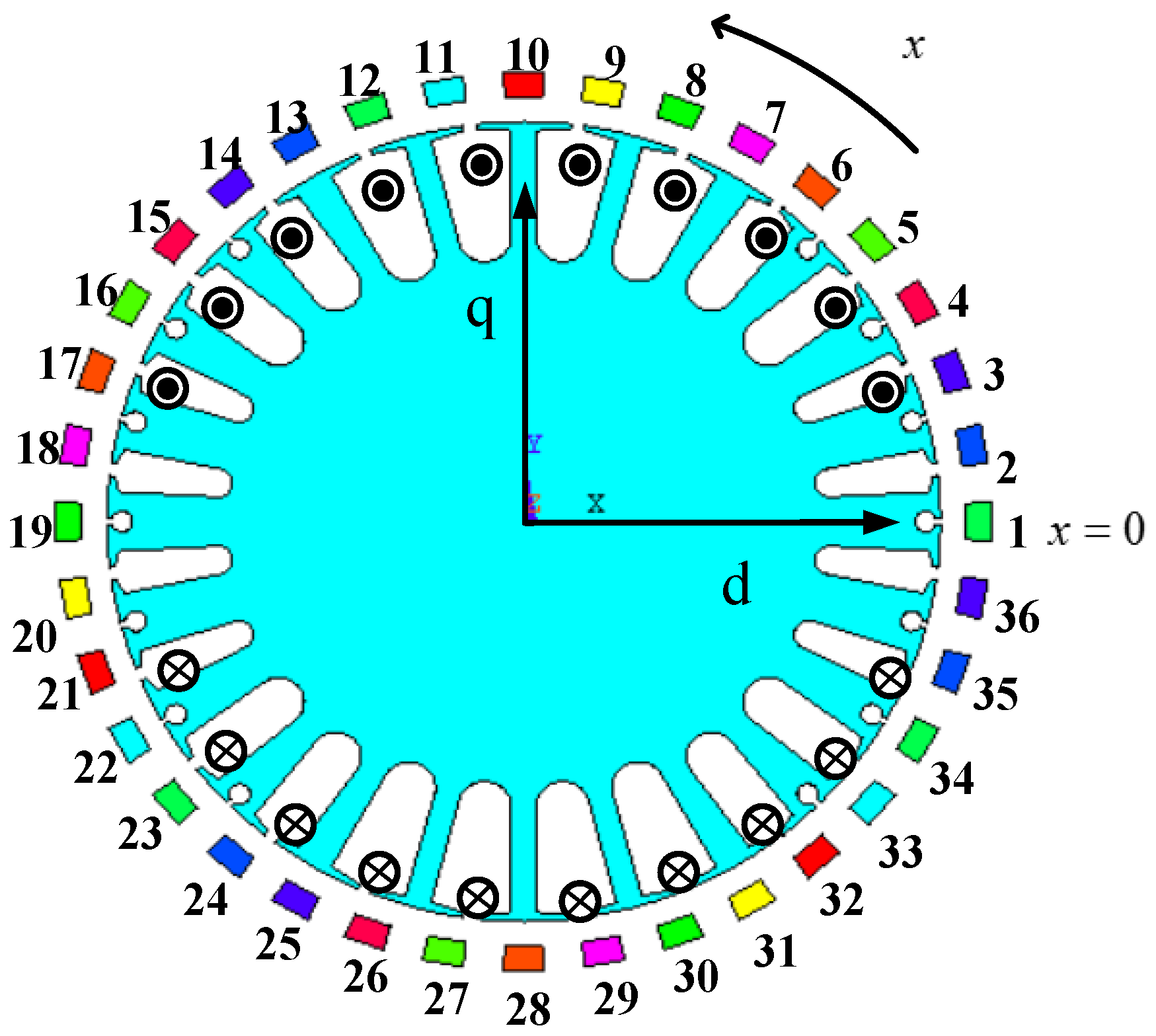
The zero point of the stator spatial coordinates x is placed in the center line of stator slot number one. A counterclockwise direction is taken as the forward direction of x, as shown in Figure 4. The expression for the μ th harmonic current of the jth coil (j = 1, 2, …) of a stator armature A phase a i (i = 1,2,...) branch is:
i s , a i , j , μ = 2 I s , a i , j , μ cos ( μ ω t + φ s , a i , j , μ )
Its MMF generated within the air gap is:
F s , a i , j , μ ( x ) = { 2 π y s 2 π w s i s , a i , j , μ , α s , a i , j , 1 x < α s , a i , j , 2 y s 2 π w s i s , a i , j , μ , 0 x < α s , a i , j , 1 or   α s , a i , j , 2 x < 2 π
where y s is the coil pitch of the stator winding, w s is the number of coil turns, and α s , a i , j , 1 and α s , a i , j , 2 are the stator coordinate electric angles corresponding to the two edges of the coil. The MMF generated by the stator A phase current and the MMF generated by ABC three phase currents can be obtained:
F s , A ( x ) = i j μ F s , a i , j , μ ( x )
F s ( x ) = F s , A ( x ) + F s , B ( x ) + F s , C ( x )

2.2.3. Air Gap Magnetic Density in Fault

In order to facilitate this calculation, the calculation results of 2.2.1–2.2.3 are converted to the stator coordinate system. Let γ 0 represent the electric angle at t = 0 of the rotor d-axis. The stator coordinate axis, γ is the rotor position angle (i.e., the electric angle of the rotor d-axis counterclockwise rotation leading over the stator coordinate axis):
γ = 0 t ω d t + γ 0
where the rotor rotates at a constant speed, γ = ω t + γ 0 . Replacing θ with x γ obtains the expression of the air gap MMF in the fault:
F δ ( x ) = F s ( x ) + F fd ( x γ ) + F d ( x γ )
For a uniform magnetic circuit, the formula for air gap magnetic density [22] can be obtained according to Equation (12):
B ( x ) = λ F δ ( x )
where λ = μ 0 / l represents the permanent per unit area, μ 0 is air gap magnetic permeability, and l is equivalent air gap length.

2.3. Analysis of Rotor UMP on Inter-Turn Short Circuit Fault

When the ISCFW occurs, the magnetic field in the air gap is no longer symmetrical, and the rotor would be subjected to UMP. The rotor UMP can be divided into radial magnetic pull and tangential magnetic pull. However, the value of radial magnetic pull is much higher than that of tangential magnetic pull. Only the radial magnetic pull of the rotor is studied, and the tangential magnetic pull is no longer considered [23,24]. Based on the distribution of air gap magnetic density on faults calculated in Section 2.2.3, electromagnetic force density (N/m2)—radially distributed at an arbitrary position along the circumference of the generator—can be obtained by means of the Maxwell stress tensor method:
f r ( x ) = B 2 ( x ) / ( 2 μ 0 )
In order to calculate the UMP on the rotor, the above equation shall be integrated along a closed path on the rotor surface:
F r = 0 2 π f r ( x ) D r o t o r L r o t o r / 2 d x
here the numerical method is used to solve the above integral. Discretization of continuous data is required. N δ units may be evenly taken on this path. An electric angle of the stator coordinates corresponding to each discrete unit is x m ( 1 m N δ ) . The radial force withstood by each unit can be obtained by calculation:
F r , m = f r ( x m ) D r o t o r L r o t o r Δ x / 2
where D r o t o r is the rotor diameter, L r o t o r is the length of rotor core, and Δ x is the difference of the stator coordinate electric angles corresponding to the two adjacent discrete units. The X-axial and Y-axial components can be obtained in the global coordinate system. Their superposition will be the X-axis component F X and Y-axis component F Y of the rotor UMP.
{ F X = m = 1 N δ F r , m cos x m F Y = m = 1 N δ F r , m sin x m
On the basis of the obtained F X and F Y , the modulus value F UMP and the direction α UMP of the UMP ( α UMP is the angle between the UMP and X-axis of the global coordinate system) can be obtained:
F UMP = F X 2 + F Y 2
α UMP = { arctan [ F Y / F X ] , [ F X 0 and F Y 0 ] arctan [ F Y / F X ] + 180 ° [ F X < 0 ] arctan [ F Y / F X ] + 360 ° , [ F X > 0 and F Y < 0 ]

3. Experiment and Simulation Verification

The UMP of the rotor cannot be measured in the experiment. Verification in this paper for a fast calculation model of the UMP is as follows. First, the correctness of the model electric quantity calculation is verified by comparing the experimental results with the simulation results of the stator and rotor currents on faults. The UMP of the rotor is calculated by means of the established generator finite element physical model, with the calculated stator and rotor currents. Then, the correctness of the fast calculation model can be indirectly verified by comparing the results of finite element analysis with the calculation results of the fast model proposed by this paper.

3.1. Experiment on ISCFW

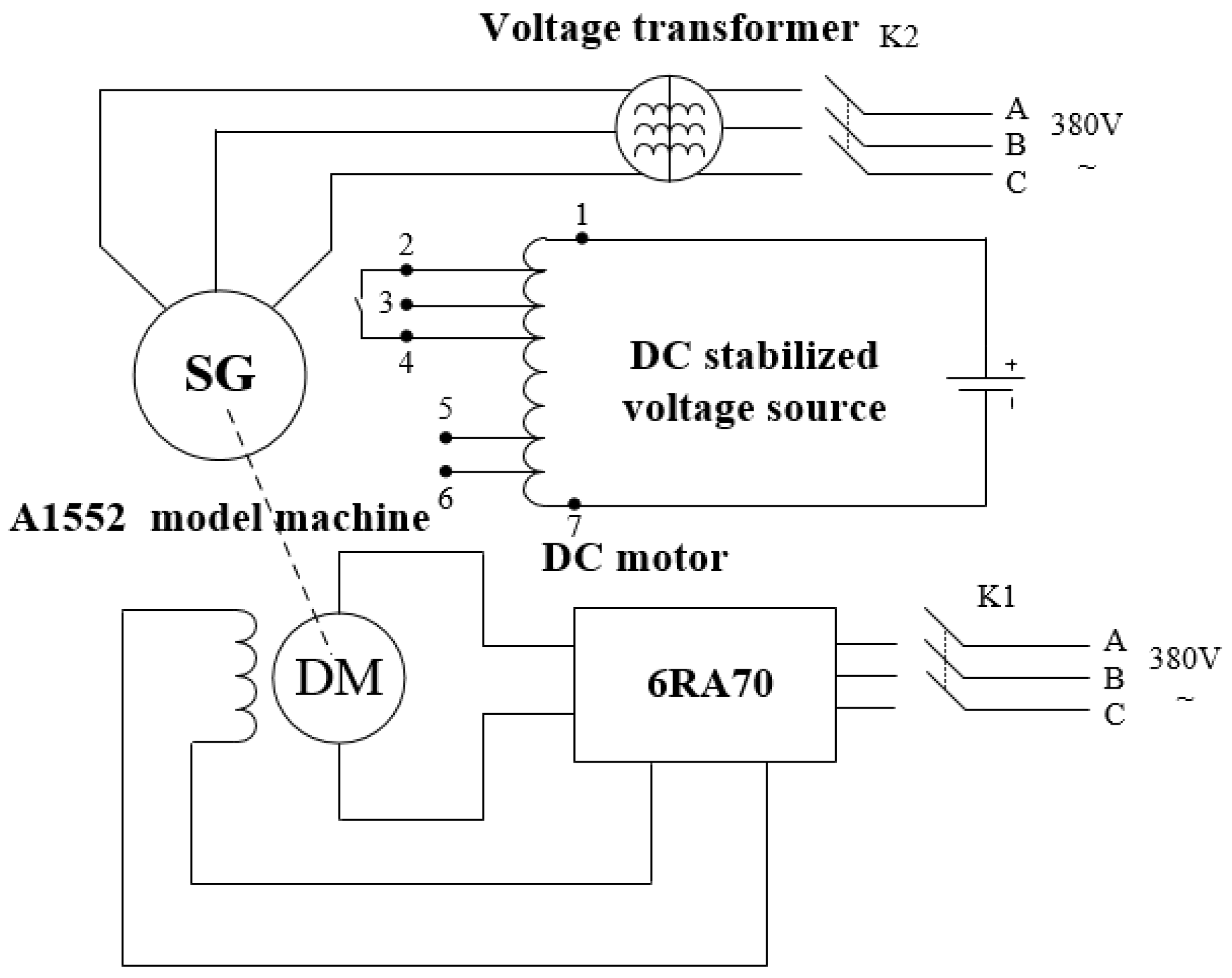
It is important to verify the accuracy of the multi-loop mathematical model. This is accomplished by calculating a one-pair pole A1552 model machine grid loaded on the inter-turn short circuit faults. A generator rotor inter-turn short circuit experiment by means of a machine model is necessary. Figure 5 is the experimental wiring diagram. The A1552 model machine is driven by a DC motor which is controlled by a SIMENS 6RA70 digital speed regulating system, with a rated speed of 3000 RPM. The machine model connects to the power grid through a three-phase voltage regulator, and the field winding is supplied by a DC stabilized voltage source with minimal ripple.
The parameters of the machine model A1552 and the structure of the rotor are shown in Table 1 and Figure 6, respectively. The rotor is a laminated iron core with two poles, comprising 24 uniformly-spaced slots, of which the number of the actual field slots is 20. There are two dead slots under each pole. Each pole has five field concentric coils, placed symmetrically in 10 field slots. The total turn number of field windings in series is 660. Seven taps are led from inside of the field winding of the machine model. In addition to two taps of the initial and terminal ends, the other five taps are used for the field winding inter-turn short circuit experiment.
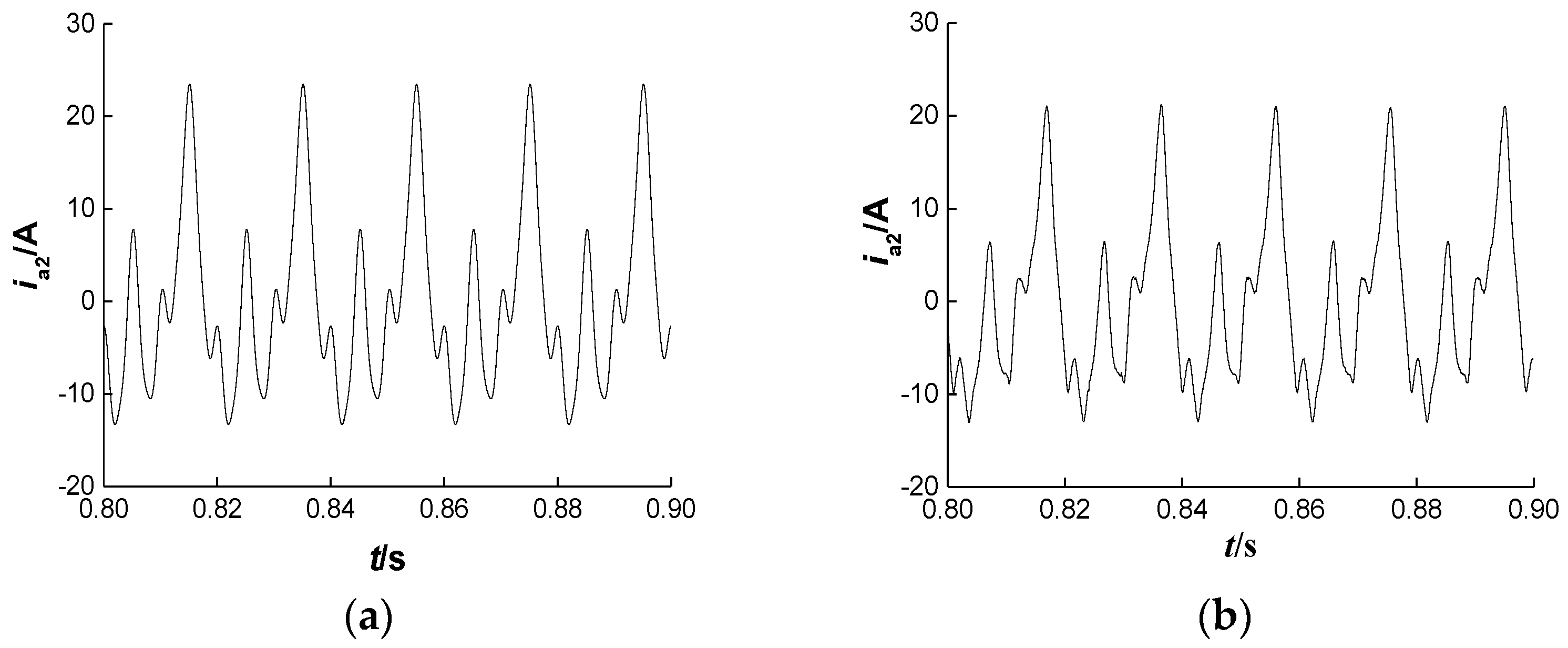
An experimental comparison with such a large number of turns is designed to eliminate deviation in the simulation and calculation errors caused by motor manufacturing factors. The experimental current waveforms of the a2 branch of the grid-connected loaded machine model agree well with the simulation waveforms using the multi-loop method, as shown in Figure 7.
In order to further verify the accuracy of the calculation with the multi-loop method, the RMS of each harmonic component of the stator and rotor steady-state currents is obtained. Fast Fourier transform (FFT) analysis is compared with the calculated steady state results, and each harmonic component is calculated with the multi-loop method, as shown in Table 2:
The experimental and simulation results with the multi-loop method are in good agreement. The mathematical model is verified as correct for calculating a grid-connected one-pair pole synchronous generator on field winding inter-turn short circuit faults. On this basis, we continue to use the multi-loop method to calculate the RMS. The phase of the rotor damp circuit and stator armature steady-state current is also calculated using Equation (1), as shown in Table 3 and Table 4:

3.2. Simulation Model and Calculation Steps

3.2.1. Finite Element Model of a Generator

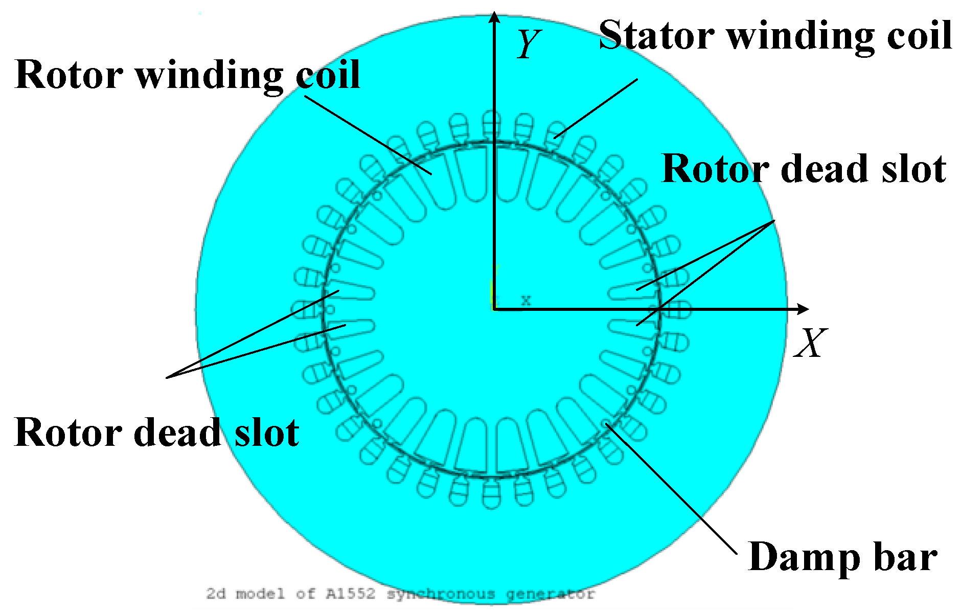
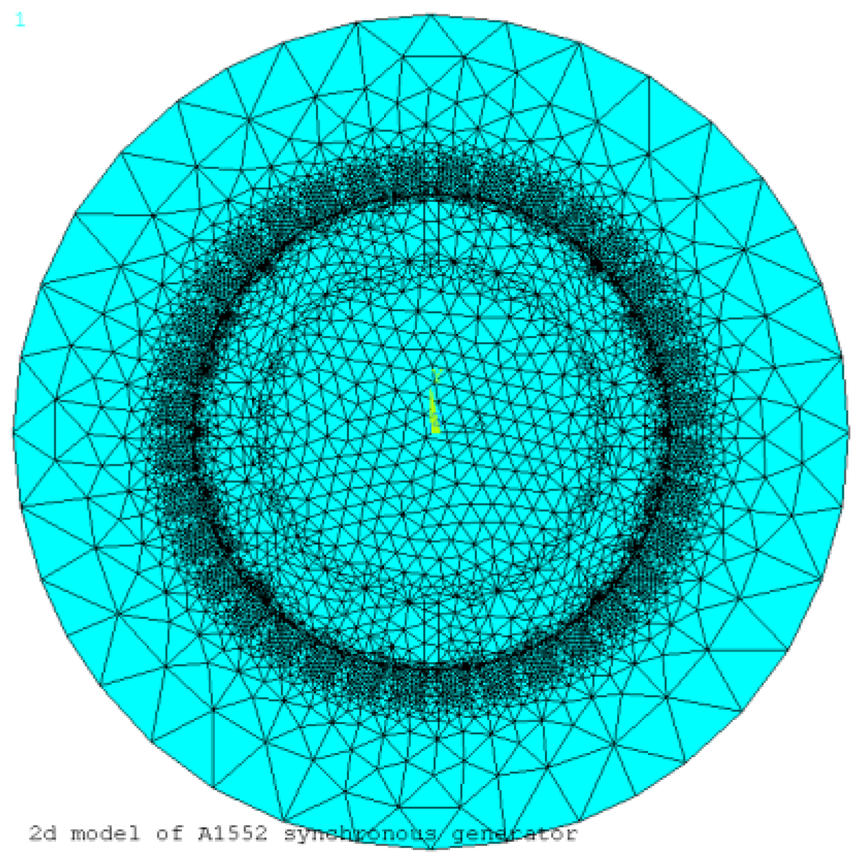
In this paper, the finite element analysis ANSYS software is used to establish the two-dimensional finite element physical model of the entire cross-section of machine model A1552, as shown in Figure 8.
The intelligent partition for the model of triangle mesh with six nodes is made. Magnetic field distribution in the air gap is the key to the coil coupling parameters analysis. In order to ensure partition density, the starting position of the partition is set at the air gap. The model after the partition is shown in Figure 9. In each unit of the partition, the kept material magnetic permeability is considered to be constant.

3.2.2. UMP Analysis Procedure with the Finite Element Method

The calculation of the UMP under a short circuit fault with the magnetic field method of finite element analysis was as follows. First, the rotor field current, damp current, stator armature current, and other related running data (using an A1552 model machine grid-connected and loaded on a rotor inter-turn short circuit fault) are calculated with the multi-loop method. The two-dimensional finite element physical model of a generator is built based on the actual size. The running data obtained in the first step are incorporated into the finite element physical model established in the second step. Next, the generator internal electromagnetic field on inter-turn short circuit faults is calculated. The magnetic density of each unit along the air gap circumference is obtained and kept. The electromagnetic force of each unit along the rotor surface, and the UMP on the whole rotor in fault are subsequently calculated. Steps three and four are repeated for the changed rotor position until the rotor rotates one revolution.
In addition, an air gap line set at the center position of the air gap by the model divides the air gap into stator and rotor air gaps. The automatic rotation of the rotor is realized by the nodes on a dividing line between the stator and rotor air gap composing different sets of coupling points.

3.3. Comparative Analysis of Analytical Model Calculation and Finite Element Calculation Results

After establishing mathematical and physical models of a generator, the air gap magnetic density distribution and the UMP on the rotor in ISCFW are obtained using the analytical model and finite element calculations. The comparison of the obtained results is as follows:
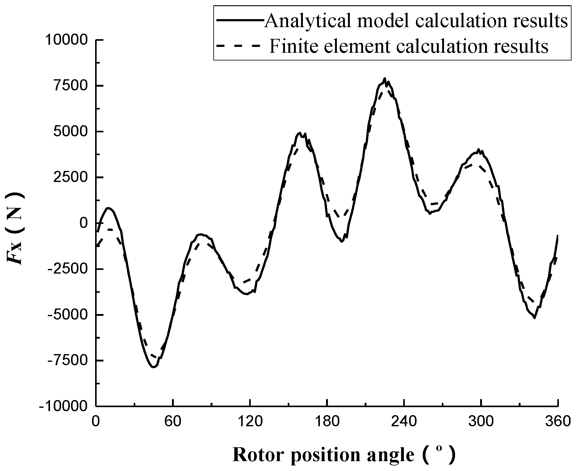
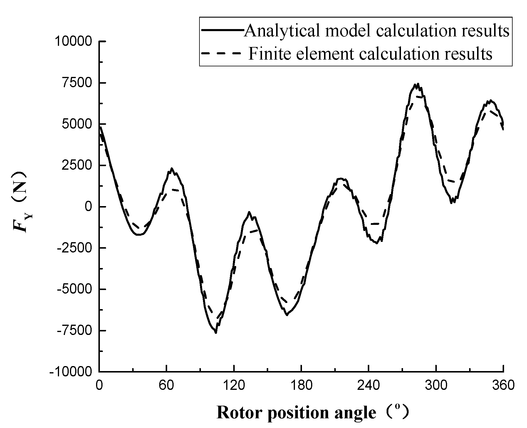
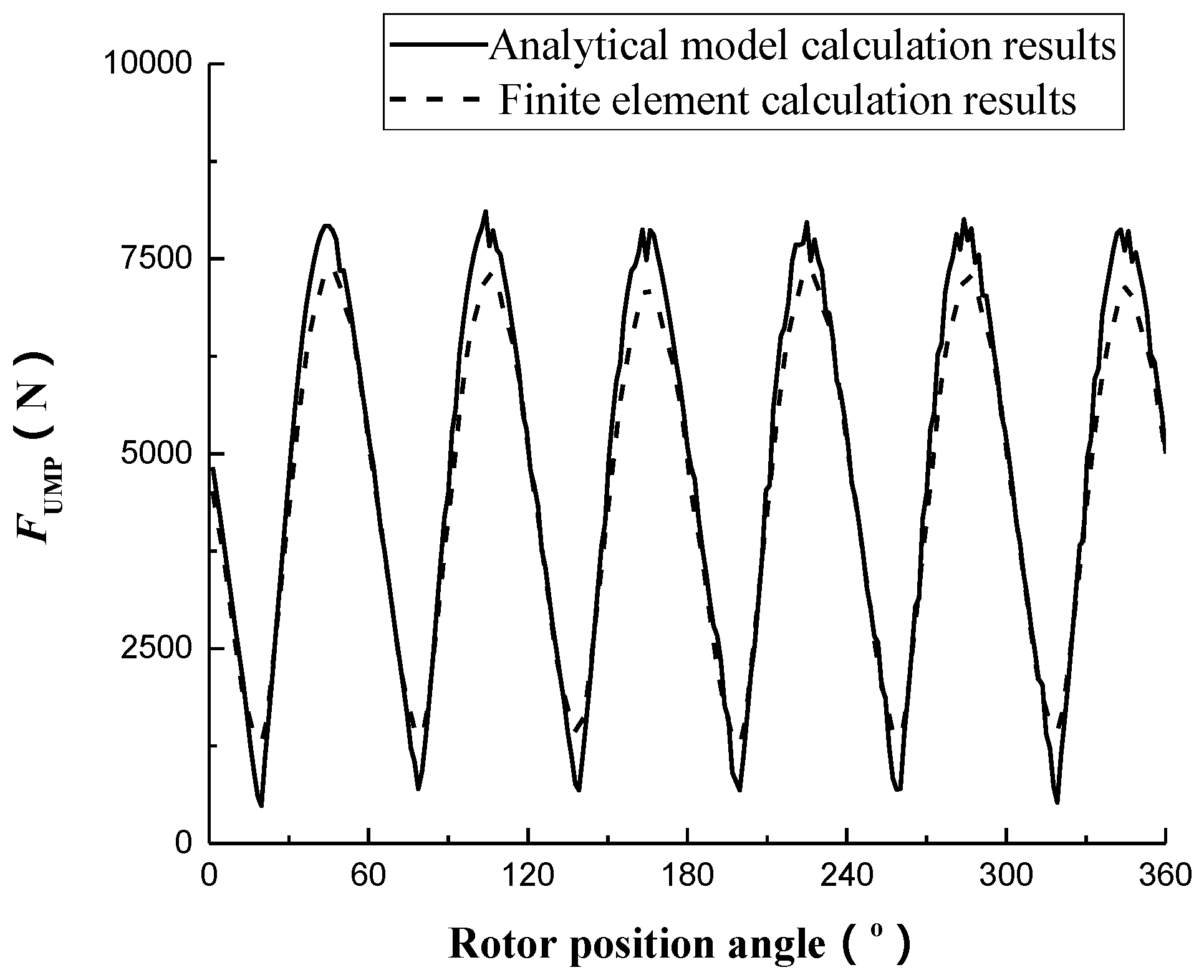
The air gap magnetic density distributions of a synchronous generator in ISCFW obtained with the analytical and finite element models are shown in Figure 10. Here the rotor position angle γ = 0 . The X-axis and Y-axis components of the UMP on the rotor are shown in Figure 11 and Figure 12. Figure 13 and Figure 14 are the direction and the modulus value of the UMP. Results show that the UMP and the rotor synchronously rotate. The amplitude periodically changes six times per rotor revolution. As seen in Figure 11, Figure 12, Figure 13 and Figure 14, the results obtained with the two methods are in good agreement, verifying the correctness of the analytical calculation model of the UMP. In addition, the finite element calculation took up to two hours, while the entire analytic model calculation took only one minute. Compared to the finite element method, the analytical model calculation has the advantages of a shorter time consumption and a higher efficiency.

4. Influence Factor Analysis of UMP

4.1. Effects of Field Winding Short Circuit Position on UMP

Post-fault MMF is the sum of the MMF produced by the normal field circuit and the MMF produced by the fault additional circuit. When the additional harmonic current of field and damp winding (caused by post-fault stator armature reaction MMF) is not considered, the MMF properties produced by the normal field circuit are the same as those before the faults. Only the effects of the MMF produced by the fault field circuit on the UMP must be analyzed. Fourier decomposition for MMF produced by the fault field concentric coil is carried out:
F fd ( x ) = v F fd , v cos v x ,   v = 1 P , 2 P , 3 P ,
The rectangular wave MMF is symmetrical around the rotor d-axis, so there is only the cosine term in Equation (20). This calculation is factored into:
F fd , v ( x ) = 1 P π P π P π F fd cos v x d x = 2 ν P π I f w k y , v
where I f is the DC component of field current, w is the number of short circuit turns, and ky,v is pitch shortening factor of the fault field concentric coils to the vth harmonic. Its computational formula is as follows:
k y , v = sin ( ν β π 2 )
where β is pitch shortening ratio of the coil.
From Equation (21) we can see that the vth harmonic MMF produced by the fault coil is proportional to the pitch shortening factor ky,v of the coil with regard to the vth harmonic for definite field current and short turns. Therefore, the RMS of the vth harmonic current induced in the stator branch and the amplitude of the space harmonic MMF induced in the air gap are both proportional to ky,v. Each harmonic of fault UMP is generated by magnetic field interactions in the air gap. The amplitude of each harmonic is only affected by ky,v. In the field test, the fundamental component of UMP is measured and observed. This paper takes the fundamental component of UMP as the main research object. UMP thereafter refers to the fundamental component of the UMP.
In order to study the influence of short circuit position on UMP, 11–55 foot field concentric coils on 30 turn short circuit faults are respectively calculated. Conditions of operation are grid-connected. The simulation results are shown in Table 5.
When the two field concentric coils with the same pitch shortening factor ky,2 respectively undergo faults, the values of UMP are similar. The UMP with larger pitch shortening factor ky,1 is slightly less than that with smaller ky,1.
When the field concentric coils with different pitches undergo short circuit faults, UMP is generated by an interaction between the fundamental MMF and the second MMF in the air gap. The fundamental MMF includes the fundamental field MMF and the MMF produced by the stator harmonic current. The fundamental field MMF can be regarded as the sum of the fundamental MMF produced by the normal field circuit and the fundamental MMF produced by the fault additional circuit. The fundamental MMF produced by the fault circuit increased with increasing ky,1, but the fundamental MMF produced by the normal field circuit remained unchanged. The superposition of the two will show a decreasing trend, but the change is minimal overall.
The fundamental current induced in the stator winding and the fundamental MMF produced by the fundamental current will also have the same variation law. The combined fundamental MMF in the air gap will decrease with increasing ky,1, but the overall change is also minimal. The size of the second MMF in the air gap is approximately proportional to ky,2. Therefore, UMP is approximately proportional to pitch shortening factor ky,2 of the fault coil. For the same ky,2, the size of UMP is negatively correlated with ky,1.

4.2. Effects of Distributed Field Winding Short Circuit Turns on UMP

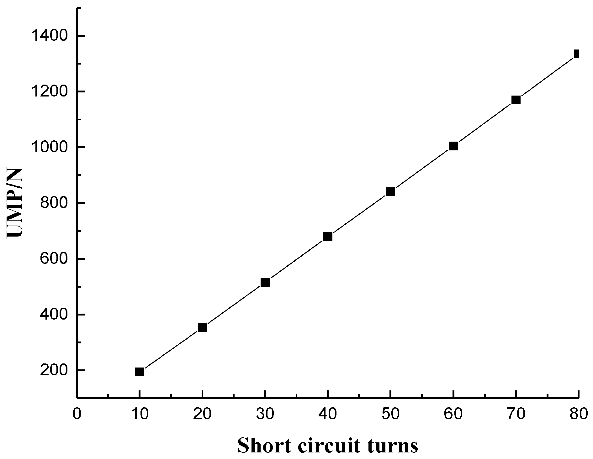
In order to study the effects of short circuit turns on UMP, 55 feet of the field winding concentric coil undergoing 10 to 80 turns were calculated. The calculation results of harmonic currents and UMP of branch a2 are shown in Table 6 and Figure 15.
UMP shows the approximate linear increase variation law with the increasing short circuit turns. From Table 6, the fundamental current of the stator branch gradually reduces with increasing short circuit turns, but the change is small. The second harmonic and field currents increase with increasing short circuit turns. The growth rate of the former increases with an increasing number of short circuit turns. The latter is proportional to the number of short circuit turns. Therefore, the second harmonic MMF in the air gap will also increase, so UMP increases with increasing short circuited turns. The fundamental MMF changes little, and overall shows a decreasing trend. The increased rate of UMP slows, and the growth rate will not increase with increasing short circuited turns. This shows a variation that is approximately proportional to the short circuit turns.

4.3. Influence of Generator Running State on UMP

When a field winding inter-turn short circuit fault occurs in a generator, the position of the short circuit and the turn number is fixed in a certain time. With the change of the generator's running state, the UMP on the rotor will change. In order to determine whether or not the field winding inter-turn short circuit fault occurs, it is very important to study the relationship between UMP and the generator’s running state.

4.3.1. Effect of Output Active Power on UMP

In order to study the effect of active power on UMP, its power factor angle (PFA) is changed. The output active power is also changed, and the reactive power is unchanged according to taps 2–4 short-circuit in the field winding of the machine model. The short circuit faults under these states are calculated.
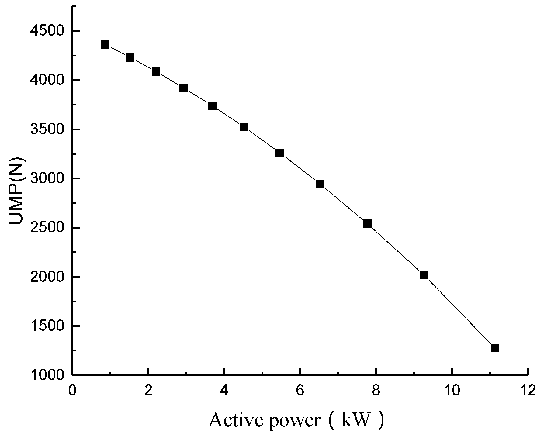
As shown in Table 7, the output active power will decrease and UMP will increase with increasing PFA. This is due to the fundamental current of the stator branch reducing with increasing PFA φ under the premise of constant output reactive power. The size of the secondary harmonic current is essentially invariant. This is because there are no changes in the field current. The fundamental MMF and the secondary MMF produced by the field current, as well as the secondary MMF produced by the stator branch second harmonic current, are all unchanged. Only the fundamental MMF produced by the stator branch fundamental current becomes smaller. Because φ > 0 , the fundamental MMF of the stator armature plays a demagnetizing role in field MMF. Therefore, the combined MMF in the air gap reduces and UMP decreases.
As seen in Figure 16, UMP decreases faster with increasing active power. The fundamental MMF produced by the stator branch fundamental current will also increase. Demagnetizing armature reaction will also be stronger, and the saturation degree in the air gap magnetic field will decrease. The higher the air gap saturation, the lower the UMP change rate. The lower the air gap saturation, the greater the UMP change rate.

4.3.2. Effect of Field Current on UMP

In order to study the effect of field current on UMP, its PFA is changed so that the field current and output reactive power are also changed. The active power is unchanged under the premise that taps 2–4 short circuit in the field winding of the machine model. The short circuit faults under these states are calculated.
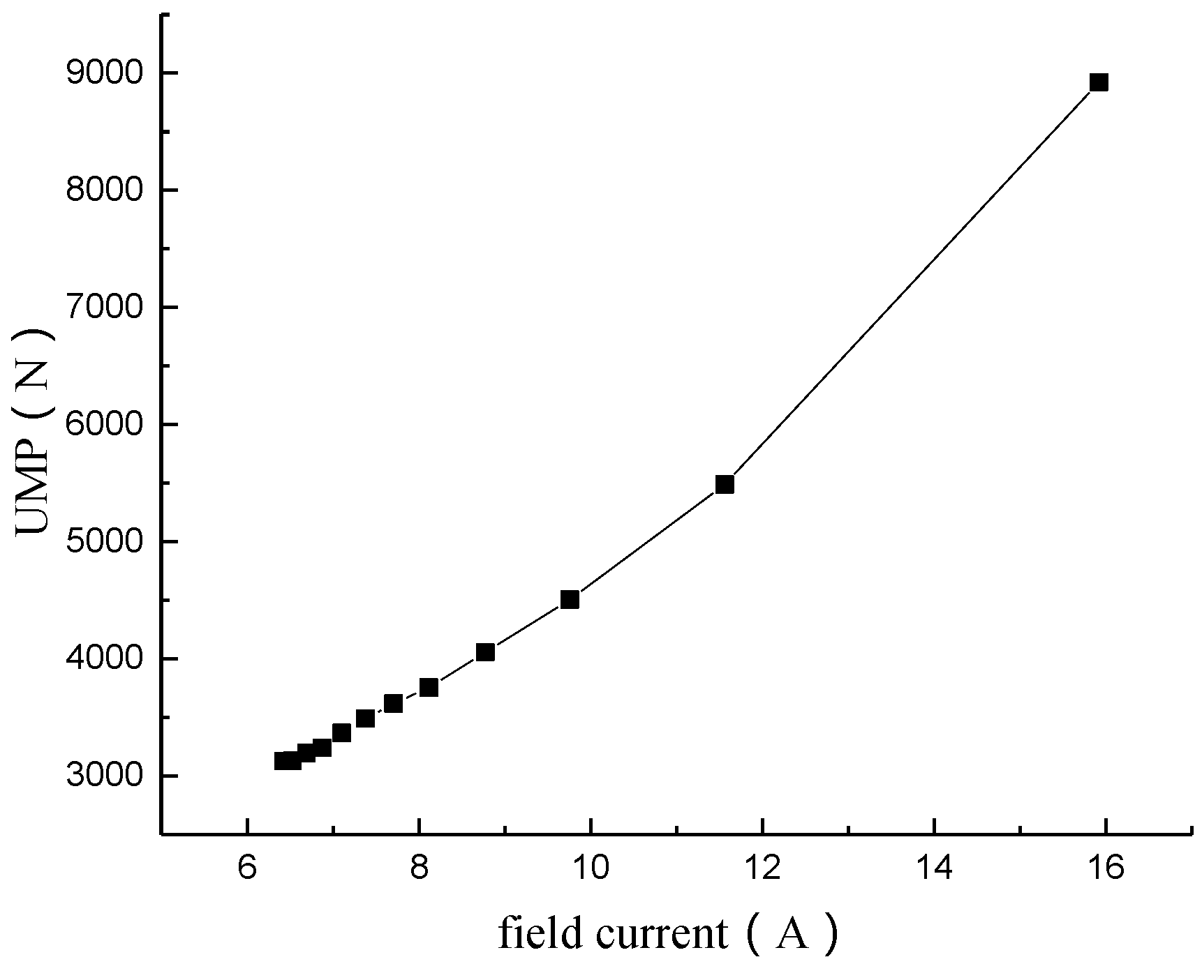
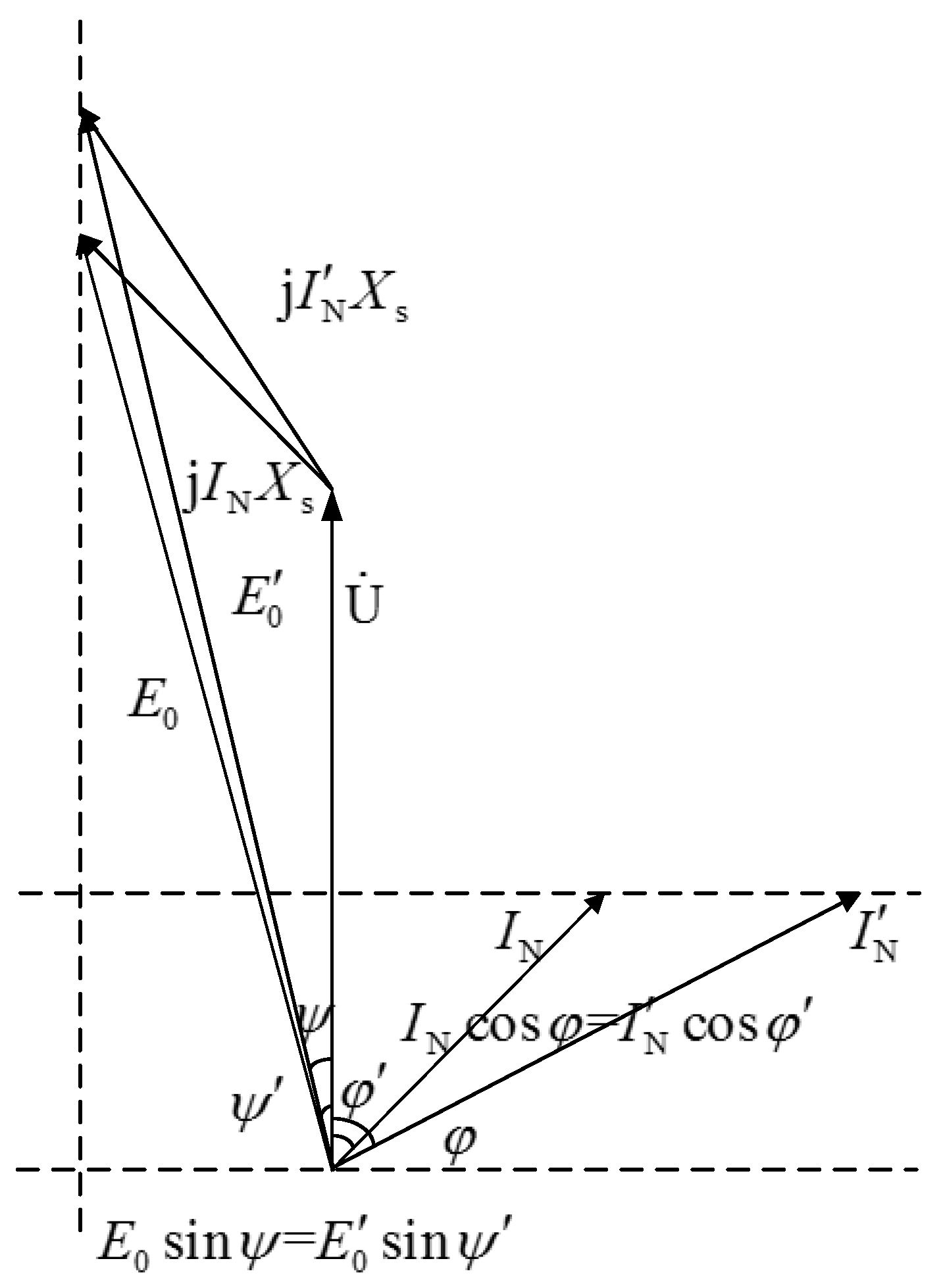
As seen in Table 8 and Figure 17 the output reactive power and UMP are increased with increasing PFA. When the PFA increases ( φ > φ ), due to unchanged output active power ( I N cos φ = I N cos φ ), the fundamental current of the stator branch and the output reactive power are increased ( I N > I N , I N sin φ > I N sin φ ). As the generator voltage U ˙ remains unchanged, the field electromotive force becomes larger ( E 0 > E 0 ), and the field current also increases ( I f > I f ), as shown in Figure 18.
The fundamental MMF and the second MMF produced by the rotor and stator will increase with increasing field current. Although the fundamental MMF produced by the stator branch current plays a demagnetizing role compared with the stator fundamental MMF, the influences of the fundamental field MMF on the combined MMF in the air gap are more obvious. UMP will also increase with increasing field current.
5. Conclusions

In this paper, a pair pole non-salient synchronous generator in ISCFW is calculated with the rapid calculation model of UMP and the finite element model. The comparison of the two results verifies the correctness and efficiency of the rapid calculation model of UMP. On this basis, the factors affecting UMP in ISCFW are analyzed. The following conclusions are drawn:
(1)
Under the premise of the same short circuit turns, UMP is approximately proportional to pitch shortening factor ky,2 of the fault coil. For the same ky,2, the size of UMP is negatively correlated with ky,1. Under the premise of the determined fault location, UMP is approximately proportional to the number of short circuit turns.
(2)
When the field current is fixed, UMP is negatively correlated with the output active power. When the output active power is unchanged, UMP is positively correlated with the field current.

Acknowledgments

This work presented in this paper was supported by the National Natural Science Foundation of China (No. 51307005) and the Fundamental Research Funds for the Central Universities (No. 2015JBM082).

Author Contributions

All authors made significant contributions to this research. More specifically, Guangtao Zhang performed the experiments, analyzed the data and wrote the paper. Liangliang Hao designed the methodology and revised the paper. Junyong Wu provided important comments on the paper’s structure.

Conflicts of Interest

The authors declare no conflicts of interest.

References

  1. He, Y.L.; Ke, M.Q.; Tang, G.J.; Jiang, H.C.; Yuan, X.H. Analysis and simulation on the effect of rotor interturn short circuit on magnetic flux density of turbo-generator. J. Electr. Eng. Elektrotech. Cas. 2016, 67, 323–333. [Google Scholar] [CrossRef]
  2. Wu, Y.C.; Li, Y.G. Diagnosis of Rotor Winding Inter-turn Short-Circuit in Turbine Generators Using Virtual Power. IEEE Trans. Energy Convers. 2015, 30, 183–188. [Google Scholar]
  3. Fiser, R.; Lavric, H.; Bugeza, H.; Makuc, D. Computations of magnetic field anomalies in synchronous generator due to rotor excitation coil faults. IEEE Trans. Magn. 2013, 49, 2303–2306. [Google Scholar]
  4. Hao, L.L.; Wu, J.Y.; Zhou, Y.Z. Theoretical Analysis and Calculation Model of the Electromagnetic Torque of Non-salient Pole Synchronous Machines with Inter-turn Short Circuit in Field Windings. IEEE Trans. Energy Convers. 2015, 30, 110–121. [Google Scholar] [CrossRef]
  5. Wu, Y.C.; Li, Y.G. Diagnosis of Short Circuit Faults within Turbogenerator Excitation Winding Based on the Expected Electromotive Force Method. IEEE Trans. Energy Convers. 2016, 31, 706–713. [Google Scholar]
  6. Ding, F.; Trutt, F.C. Calculation of frequency spectra of electromagnetic vibration for wound-rotor induction machines with winding faults. Electr. Mach. Power Syst. 1988, 14, 137–150. [Google Scholar] [CrossRef]
  7. Trutt, F.C.; Sottile, J.; Kohler, J.L. Detection of AC machine winding deterioration using electrically excited vibrations. IEEE Trans. Ind. Appl. 2001, 37, 10–14. [Google Scholar] [CrossRef]
  8. Trutt, F.C.; Sottile, J.; Kohler, J.L. Condition monitoring of induction motor stator windings using electrically excited vibrations. In Proceedings of the 37th Industry Applications Annual Meeting, Pittsburgh, PA, USA, 13–18 October 2002; pp. 2301–2305. [Google Scholar]
  9. Wu, Y.C.; Li, Y.G.; Li, H.M.; Zhang, W.J. An Analysis of the Impact of Rotor Winding Inter turn Short Circuits on Turbine Generator Operating Variables. Electr. Power Compon. Syst. 2015, 43, 674–684. [Google Scholar]
  10. Tenhunen, A. Finite-element calculation of unbalanced magnetic pull and circulating current between parallel windings in induction motor windings non-uniform eccentricity motor. In Proceedings of the Electromotion, Bologna, Italy, 19–20 June 200l; pp. 19–24.
  11. Tenhunen, A.; Benedetti, T.; Holopainen, T.P.; Arkkio, A. Electromagnetic forces in cage induction motors with rotor eccentricity. In Proceedings of the IEEE IEMDC, Madison, WI, USA, 1–4 June 2003; Volume 3, pp. 1616–1622. [Google Scholar]
  12. Wang, S.T.; Li, Y.G.; Li, H.M.; Tang, G.J. A Compositive Diagnosis Method on Turbine Generator Rotor Winding Inter-turn Short Circuit Fault. In Proceedings of the IEEE International Symposium on Industrial Electronics, Montreal, QC, Canada, 9–12 July 2006; pp. 1662–1666. [Google Scholar]
  13. Wang, S.T.; Li, Y.G.; Li, H.M. The new diagnosis method of rotor winding inter-turn short circuit fault and imbalance fault based on stator and rotor vibration characteristics. In Proceedings of the 8th International Conference on Electrical Machines and Systems, Nanjing, China, 27–29 September 2005; pp. 2207–2210. [Google Scholar]
  14. Wan, S.T.; He, Y.L.; Zhan, C.G. Effect of internal power-angle on turbo-generator rotor vibration characteristics under eccentricity faults. Trans. Can. Soc. Mech. Eng. 2014, 38, 63–79. [Google Scholar]
  15. Wan, S.T.; Zhan, C.G.; Yao, X.F.; Deng, Y.M.; Zhou, G.W. Investigation on electromagnetic forces and experimental vibration characteristics of stator end windings in generator. Trans. Can. Soc. Mech. Eng. 2014, 38, 331–345. [Google Scholar]
  16. Sun, Y.G.; Wang, X.H.; Gui, L.; Wang, W.J. Simulation research on inter-turn short circuits of field windings in synchronous machines. Adv. Technol. Electr. Eng. Energy 2008, 27, 5–10. [Google Scholar]
  17. Sun, Y.G.; Hao, L.L.; Wang, X.H. Inductance calculation of the multi-loop model for inter-turn short circuits of field windings in non-salient-pole synchronous machine. Electr. Power Syst. 2013, 34, 55–60. [Google Scholar]
  18. Wang, X.H.; Chen, S.L.; Wang, W.J.; Sun, Y.G.; Xu, L.Y. A study of armature winding internal faults for turbo generators. IEEE Trans. Ind. Appl. 2002, 38, 625–631. [Google Scholar] [CrossRef]
  19. Hao, L.L.; Sun, Y.G.; Qiu, A.R.; Wang, X.H. Steady-State Calculation and Online Monitoring of Inter-turn Short Circuit of Field Windings in Synchronous Machines. IEEE Trans. Energy Convers. 2012, 27, 128–138. [Google Scholar] [CrossRef]
  20. Huang, Z.G.; Sun, Y.G.; Wang, S.M.; Yu, X.W. Analysis and diagnosis on open-circuit fault of diode rectifier in 12-phase synchronous generator system. In Proceedings of the 16th European Conference on Power Electronics and Applications (EPE’14-ECCE Europe), Lappeenranta, Finland, 26–28 August 2014. [Google Scholar]
  21. Hao, L.L.; Wu, J.Y.; Sun, Y.G.; Wang, X.H. Simplified mathematical model of inter-turn short circuit of field windings in hydro-generators and its application. Sci. China Technol. 2013, 56, 898–909. [Google Scholar] [CrossRef]
  22. Gao, J.D.; Zhang, L.Z.; Wang, X.H. AC Machine Systems; Tsinghua University Press: Beijing, China, 2009. [Google Scholar]
  23. Frosini, L.; Pennacchi, P. The effect of rotor eccentricity on the radial and tangential electromagnetic stresses in synchronous machines. In Proceedings of the 32nd IEEE IECON, Paris, France, 6–10 November 2006; pp. 1287–1292. [Google Scholar]
  24. Li, Y.; Hao, L.L.; Sun, Y.G. The Analysis of UMP Caused by Non-salient Pole Synchronous Generator Rotor Winding Inter-turn Short Circuit Fault. Autom. Electr. Power Syst. 2016, 40, 81–89. [Google Scholar]
Figure 1. Magnetic motive force (MMF) produced by concentric field coil of field windings.
Energies 10 00732 g001
Figure 2. Loops of field windings with inter-turn short circuit.
Energies 10 00732 g002
Figure 3. Damping loop structure diagram.
Energies 10 00732 g003
Figure 4. The stator coordinate and stator slot position.
Energies 10 00732 g004
Figure 5. Experimental wiring diagram.
Energies 10 00732 g005
Figure 6. Rotor lamination and field winding’s taps of A1552 model machine.
Energies 10 00732 g006
Figure 7. Steady-state waveform in branch a2 under inter-turn circuit of taps 2–4 under load condition connected to power grid. (a) Simulation waveform; (b) Experimental waveform.
Energies 10 00732 g007
Figure 8. Finite element model of the generator.
Energies 10 00732 g008
Figure 9. Finite element model meshed by triangle elements.
Energies 10 00732 g009
Figure 10. The flux density distribution of air gap in fault.
Energies 10 00732 g010
Figure 11. The X-axis unbalanced magnetic pull (UMP) of rotor in fault.
Energies 10 00732 g011
Figure 12. The Y-axis UMP of rotor in fault.
Energies 10 00732 g012
Figure 13. The UMP direction of rotor in fault.
Energies 10 00732 g013
Figure 14. The UMP module value of rotor in fault.
Energies 10 00732 g014
Figure 15. Relationship between short circuit turns and UMP.
Energies 10 00732 g015
Figure 16. Relationship between UMP and output active power.
Energies 10 00732 g016
Figure 17. Relationship between UMP and field current.
Energies 10 00732 g017
Figure 18. Synchronous generator grid-connected operation vector diagram.
Energies 10 00732 g018
Table 1. Parameters of A1552 non-salient pole model machine.
VariableParameterVariableParameter
Rated capacity (kW)12Number of series coils per branch of stator6
Rated voltage (V)400Pitch of stator coil15
Rated field current (A)8.5Number of conductors per slot of stator12
No-load field current (A)6.0Number of rotor slots24
Rated power factor0.8 (hysteresis)Series turns per pole of field winding330
Rated frequency (Hz)50Field winding parallel branch1
Number of pole-pair (P)1Actual rotor slots20
Gap length (mm)1.5Number of damp bars per pole of rotor7
Number of parallel branches per phase of stator2
Table 2. Different harmonics root mean square (RMS) of steady state current under inter-turn circuit of taps 2–4 under load condition connected to power grid.
Each Harmonic of the Steady State Electrical QuantitiesPre-Fault Experimental Results (A)After Fault (during Steady-State)
Experiment Results (A)Calculation Results (A)Relative Error (%)
Harmonic RMS of current in a1 branchFundamental7.115.636.7119.1
2nd0.325.445.888.1
3rd0.360.480
4th0.023.112.887.4
Harmonic RMS of current in a2 branchFundamental7.035.786.7115.9
2nd0.335.465.887.8
3rd0.280.610
4th0.023.102.887.0
Normal field circuit currentDC component5.288.658.683.5
Fault field circuit current−8.2−8.223.0
Table 3. Rotor damping loop steady-state current RMS and phase of fault experiment.
RMS and Phase of Damp Circuit Current
Circuit No.RMS (A)Phase (°)Circuit No.RMS (A)Phase (°)
130.59−99.31841.8962.12
229.72−70.44940.9655.00
315.28−47.051032.3480.71
450.94−92.291151.62−129.60
533.8262.651214.01−169.10
639.1488.41329.44−149.60
738.1772.221431.21−121.50
Table 4. Stator armature steady state current RMS and phase of fault experiment.
Fundamental 2nd4th
A1RMS (A)6.7085.8842.882
Phase (°)70.09−154.2135.7
A2RMS (A)6.7085.8842.882
Phase (°)70.0925.82−44.32
B1RMS (A)6.7085.8842.882
Phase (°)−49.91−34.1815.68
B2RMS (A)6.7085.8842.882
Phase (°)−49.91145.8−164.3
C1RMS (A)6.7085.8842.882
Phase (°)−169.9085.82−104.3
C2RMS (A)6.7085.8842.882
Phase (°)−169.90−94.1875.68
Table 5. UMP and the RMS of stator harmonic current when field concentric coils with different pitches undergo the same turn short circuit.
Short Position11 Feet22 Feet33 Feet44 Feet55 Feet
Pitch shortening ratio3/125/127/129/1211/12
ky,v (v = 1)0.380.610.790.920.99
ky,v (v = 2)0.710.970.970.710.26
Fundamental current (A)7.607.347.136.986.91
2nd current (A)1.582.082.021.460.50
UMP (kN)1.471.991.941.390.515
Table 6. The RMS of the harmonic current of stator and rotor when field concentric coil undergoes different short circuit turns.
Short Circuit TurnsField Current (A)Fundamental Current (A)2nd Current (A)
105.387.060.16
205.466.980.33
305.556.910.50
405.646.830.68
505.736.750.87
605.826.661.06
705.926.581.26
806.026.491.46
Table 7. Operation data of A1552 model machine field winding on taps 2–4 short circuit. PFA: power factor angle.
PFA (°)Fundamental Current (A)2nd Current (A)Active Power (kW)UMP (kN)
33.1811.986.4211.131.27
38.1810.586.369.272.02
43.189.5246.317.772.54
48.188.7146.296.532.94
53.188.0786.275.463.26
58.187.5836.254.533.52
63.187.1986.243.693.74
68.186.8956.232.923.92
73.186.6756.232.214.09
78.186.5126.221.534.23
83.186.4096.220.874.36
Table 8. Operation data of A1552 model machine field winding on taps 2–4 short circuit.
PFA (°)Field Current (A)Fundamental Current (A)2nd Current (A)Reactive Power (kW)UMP (kN)
28.186.432.894.601.253.12
33.186.533.034.681.603.13
38.186.693.224.802.003.19
43.186.873.464.932.433.24
48.187.103.785.092.963.36
53.187.384.215.293.593.49
58.187.714.805.524.403.62
63.188.125.645.825.473.75
68.188.776.906.296.994.05
73.189.768.926.999.364.50
78.1811.5612.718.2813.675.49
83.1815.9222.1311.4024.158.92