
An Investigation of Fuel Mixing and Reaction in a CH4/Syngas/Air Premixed Impinging Flame with Varied H2/CO Proportion

Department of Mechanical Engineering, National Taiwan University, Taipei 10617, Taiwan
*
Author to whom correspondence should be addressed.
Energies 2017, 10(7), 900; https://doi.org/10.3390/en10070900
Submission received: 26 April 2017
/
Revised: 12 June 2017
/
Accepted: 27 June 2017
/
Published: 1 July 2017
(This article belongs to the Section I: Energy Fundamentals and Conversion)
Abstract
:For industrial applications, we propose a concept of clean and efficient combustion through burning syngas on an impinging burner. We performed experimental measurements of particle image velocimetry, OH radical (OH*) chemiluminescence, flame temperature, and CO emission to examine the fuel mixing and reaction of premixed impinging flames of CH4/syngas/air with H2/CO in varied proportions. The velocity distribution of the combustion flow field showed that a deceleration area in the main flow formed through the mutual impingement of two jet flows, which enhanced the mixing of fuel and air because of an increased momentum transfer. The deceleration area expanded with an increased CO proportion, which indicated that the mixing of fuel and air also increased with the increased CO proportion. Our examination of the OH* chemiluminescence demonstrated that its intensity increased with increased CO proportion, which showed that the reaction between fuel and air accordingly increased. CO provided in the syngas hence participated readily in the reaction of the CH4/syngas/air premixed impinging flames when the syngas contained CO in a large proportion. Although the volume flow rate of the provided CO quadrupled, the CO emission increased by only 12% to 15%. The results of this work are useful to improve the feasibility of fuel-injection systems using syngas as an alternative fuel.
1. Introduction
The avoidance of excessive consumption of hydrocarbon fuels and the implementation of clean combustion have become major global concerns in recent decades. Syngas, a clean and alternative fuel, has a great potential to replace hydrocarbon fuels in combustion applications, especially in integrated-gasification-combined-cycle systems (IGCC) [1,2]. Syngas, which is comprised mainly hydrogen (H2) and carbon monoxide (CO), is generally derived from the gasification of solid fuel feedstock such as coal, biomass, and refinery residue. The feedstock and gasification processes cause substantial variations in the composition of syngas, which lead to appreciably altered combustion characteristics [1,2,3]. The variable composition of syngas affects both the physical properties and the chemical reactions in combustion such as the flame stability, flame-flow interactions, and the emission of pollutants. The characteristics of syngas combustion, including flame propagation speed [4,5,6,7], chemical-kinetic mechanism [8,9], and flame structure [4,10], have been widely studied, as summarized [1]. Hydrogen is present in syngas in a large proportion, which induces flame instability [11] such as the opening of the flame tip and flashback issues [4,12,13,14]. To improve the safety of the use of hydrogen, a mixture of hydrocarbon and hydrogen without rapid chemical kinetics has been examined [12,15]. Another major component of syngas, carbon monoxide, is the leading intermediate during many combustion processes. The strongly bound molecular structure of carbon monoxide imposes a great activation energy for the direct reaction of CO with O2, which impedes the ignition and combustion of CO [15]. In using syngas for combustion, the improvement of the oxidation of CO becomes an important issue. In syngas combustion, the oxidation of CO can be accelerated significantly because the chain reaction of H2 and O2 provides OH radicals for CO to react as CO + OH → CO2 + H [15,16,17]. The H atoms from that reaction then recycle to participate in chain reactions with O2 [15], thereby promoting the combustion of CO within syngas as long as sufficient O2 is available.
To facilitate syngas combustion, the adoption of a suitable burner contributes to the combustion reactions of syngas through the improved mixing of syngas and oxygen. The varied configuration of a burner causes a concomitant variation of the flow field of combustion and hence affects the mixing characteristics and the combustion performance. An impinging flow field, formed from the mutual impingement of multi-jets, has attracted interest in the investigation of the mixing characteristics of fuel and oxidizer in many fuel-injection systems [18,19,20,21,22,23,24,25,26,27]. Jet-impinging configurations have been extensively used and investigated in gas turbines, internal-combustion engines, and jet-propulsion systems because of their simple geometry and thorough mixing of fuel and oxidizer [20,24,25,26,27,28,29,30,31]. In a non-reactive flow, the total pressure and the mixing section of the impinging flow in the vertical direction increase with the increasing angle of inclination of the jets [19,22,23]. The turbulence intensity attains a maximum value behind the intersection of the jets [20], which enhances the mixing rate of the flow. In a reactive flow, the non-premixed impinging flame of syngas has been thoroughly investigated in the jet-to-plate flame configuration using direct numerical simulation [28,29,30,31]; the researchers reported that both the near-wall flame characteristics and the micro-mixing behavior were greatly affected by the composition of syngas. An addition of CO plays an important role in the H2-rich combustion, which caused the appearance of possible partially premixed regions in the H2/CO non-premixed flame [28], but CO at a large concentration tended to induce the local flame extinction of the syngas flame, wherein the fluid parcels concentrated in the rich-side of the stoichiometric mixture fraction [30]. Further, the vortical structures in the flow field of the H2-rich flame became weaker than that of the H2-lean flame because of the great diffusivity of H2 [31]. For a jet-to-jet impinging flame, the temperature distribution along the center-line plane of an impinging flame yielded a rate of development greater than for a single jet flame because of the turbulent interaction and thorough mixing of the flow during the jet impingement. The blow-off limit of the impinging flame hence had a range greater than for a single jet flame [24]. Furthermore, the flame lift-off position, flame stability, and NOx emission were controlled with a triple-jet impinging burner through the modulation of the angle of inclination and the distance separating the oxygen jets [25,26]. In our previous work, an impinging flame was generated with a V-shaped burner [27]; the impingement of the two flames enhanced the mixing and the pre-heating of fuel because the interaction between flame and flow improved within the impinging area. For those advantages of an impinging burner such as the simple geometry, the benefit of fuel-air mixing, and the enhanced heat transfer we employed a self-designed impinging burner to undertake the present work. Up to now, most research concerning jet-to-jet impinging flames has been focused on diffusion flames with hydrocarbon fuels so information about the investigation of a premixed or partially premixed impinging flame using syngas as a principal fuel is still lacking. Furthermore, varying the proportions of H2 and CO in syngas might cause a variation in its fuel mixing and reaction, which must be further examined when a jet-impinging flame consumes syngas as the combustible fuel.
In the present work, we burned a fuel mixture of syngas and methane on an impinging burner. Our main aim was to understand the effects of varied H2/CO proportions on the fuel mixing and reaction of a premixed impinging flame using syngas as a principal fuel. The operating ranges, the distribution of velocity in the combustion flow field, the chemiluminescence of OH*, the flame temperature, and the CO emission were experimentally investigated, as we discuss here. The results of this work provide practical information for the application of syngas on an impinging burner.
2. Experiments
2.1. Experimental Setup and Parameters
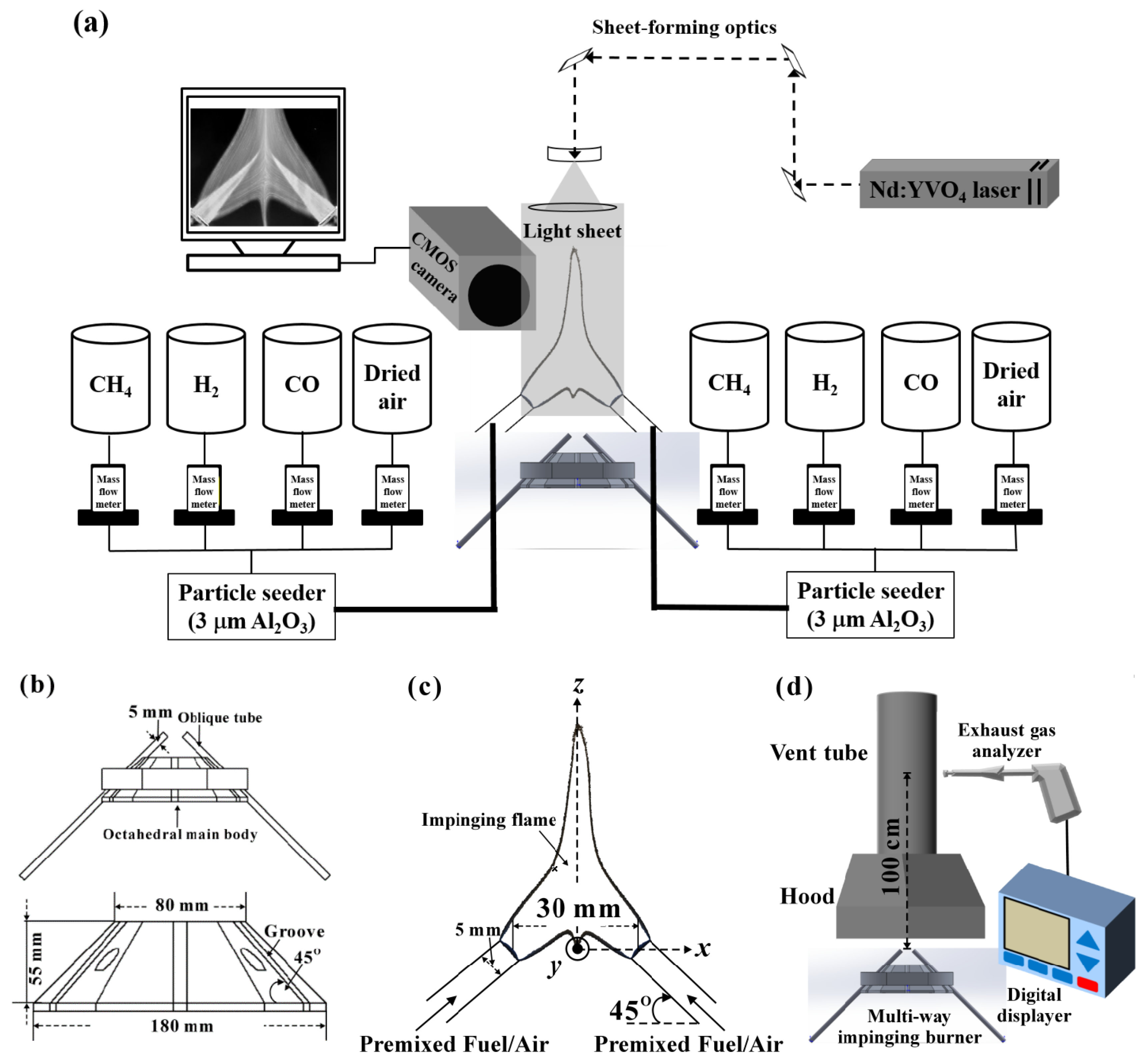
To assess the effects of varied proportions of H2 and CO on a premixed impinging flame of CH4, syngas, and air, we applied an injection burner with inclined jets to generate an impinging flame. The experimental devices included a multi-jet injection burner with inclined jets, mass flowmeters, high-pressure gas cylinders, and a system for the exhaust gas, shown in Figure 1. The burner had a special design with inclined injection jets, allowing the octahedral main body, with grooves at angles of 45° from the horizontal axis, to have up to eight fuel tubes in a radial distribution. The fuel jets intersected each other on the central axis of the burner. The inner diameter (i.d.) of the circular fuel tube, D, was 5 mm (i.d. = 5 mm); a fixed cover was locked above it to ensure that the circular fuel tube was maintained in position. The fixed inclined angle in the present work was 45°; the distance (from exit to exit) between the fuel tubes was fixed at 30 mm. The burner and fuel tubes were made of stainless steel (high-temperature resistant, 310S); the arrangement of fuel tubes is shown in Figure 1b,c, with the reference coordinate system in Figure 1c. The blended fuel was composed of methane (instrument grade, CH4, 99.5%) and syngas; the syngas was prepared from hydrogen (H2, 99.99%) and carbon monoxide (CO, 99.99%). The fuel and dry air (N2 79%, O2 21%) were supplied from high-pressure cylinders and controlled with digital mass flowmeters to enable a stable output to be maintained to the burner exits, shown in Figure 1a.
For equivalence ratios φ = 0.8 to 2.0, the proportion of hydrogen and carbon monoxide (H2/CO) in syngas was varied from H2/CO = 100/0 to H2/CO = 0/100. The flow velocity at the burner exit (Uexit) was 5.0 m/s for a constant total rate of volume flow, Vtotal = 11.78 L/min (air + fuel), with the Reynolds number Re varying from 1401 to 1701. The Reynolds number of the fuel jet was calculated based on the fuel/air mixture as:
in which μmix was calculated [32] as:
The density of the mixture (ρmix) was based on the ideal-gas equation of state. Under conditions of a constant temperature and pressure, the density of the mixture was determined as
in which Yi is the molar fraction of component i; is the density of component i; Mi is the molecular mass of component I; and is the dynamic viscosity of component i.
The constant rate of volume flow of the input methane was 0.50 L/min (accounting for 10.96–27.20% of the total fuel). The volume flow rates and the volume concentrations of hydrogen and carbon monoxide were determined and obtained through the setup of experimental parameters, shown in Table 1. The experimental parameters, referred to in [32], were calculated as:
2.2. Particle Image Velocimetry and OH* Chemiluminescence
Information about both the flow and combustion fields occurring in a CH4/syngas/air premixed impinging flame was obtained from non-intrusive particle image velocimetry (PIV) and the chemiluminescence of OH radicals, as shown in Figure 1a. The PIV was measured with a laser light sheet on the uniform flow field; a laser (Nd:YVO4, cw, maximum power output 12 W, wavelength 532 nm) served as a lamp for these measurements. The laser beam was led through an optical path to a cylindrical lens before the observation zone and was then scattered to become a light sheet of thickness 1 mm in the test section. A high-speed charge-coupled device (CCD) camera (COMS, Phantom V7.3, ISO 4800 mono, maximum resolution 800 × 600 pixels, shutter speed 6688 fps) with a lens (Nikon Nikkor, AF Micro-Nikkor 60 mm, f/2.8D, Tokyo, Japan) was used to capture images and video. Powdered alumina (Al2O3, 3 μm) served as seeding particles that were mixed with the blended fuel in the self-designed particle seeder and jet in the test section [27,33]. The PIV post-process calculations were conducted with software (Insight 5, TSI) [34]. The chemiluminescence of free radicals is useful in investigating combustion reactions because of its simple principle and convenient experimental operation. The chemiluminescence of OH* is regarded as an indicator of the rate of heat release and of the reaction zone in the reactive flow [35]. We captured the chemiluminescence images of OH radicals with a characteristic emission band at 307 nm. The high-speed CCD camera (Phantom V7.3, Wayne, NJ, USA) was used with a lens (Nikon PF10545MF-UV, Tokyo, Japan) and a filter at 307 nm for OH* chemiluminescence. Image processing was performed on grey-scale images of chemiluminescent intensity obtained with the high-speed camera. These images were converted to color charts of relative strength to facilitate visual interpretation through a self-developed program (in MATLAB).
2.3. Flame Temperature and Exhaust Gas
For temperature measurement, the system was comprised of a thermocouple (OMEGATM R-type, Pt/Pt-13Rh, 0–1600 °C, tolerance range ±0.75%, wire diameter 25 μm), a digital temperature display (GIGARISE SE6000, Taipei, ROC), and a mobile platform with a control system for a micro-stepping motor to position the thermocouple. The operating precision of the platform was 2 mm/turn (resolution 1.25 μm/step), ensuring a consistent and representative measurement point for each experiment. The thermocouple was carefully calibrated; the average temperature was calculated. Since iron oxide deposited on the thermocouple had a great influence on the radiation correction, the thermocouple was cleaned completely to ensure an accurate correction when fuel containing CO was burned [36]. As the estimated radiation correction was approximately 250 °C, the actual temperature might be greater than the uncorrected temperature by 300 °C [37], but the temperature data before correction can still serve to distinguish the variation of the flame temperature.
We measured the emission of CO in the exhaust gas because this emission during the syngas combustion is crucial to distinguish the reaction level [38,39]. Figure 1d shows the experimental setup for the collection of the exhaust gas; a hood method was applied to analyze the exhaust gas [40]. The hood (cross section 1225 cm2), which maintained a stable condition for combustion to collect the exhaust gas, was installed 10 cm above the exit of the burner. The exhaust gas that was collected with the hood flowed into a vent tube (i.d. = 15 cm); the probe of a portable gas analyzer (RBR Ecom-B, Shefford, UK), which detected CO from 0 to 4000 ppm, was inserted into the vent tube 100 cm above the burner exit to sample the exhaust gas.
The sampling data of the flame temperature and CO exhaust were recorded ten times over a total sampling duration. We used the averaged data for the analysis of uncertainty [41]; the maximum uncertainties (two standard deviations, 95% confidence level) were flame temperature at 1.5% and CO emission at 2%. The experimental measurements of the flame temperature and the CO emission were reported in our previous work [13,27].
3. Results and Discussion
3.1. Operating Range and Flame Patterns
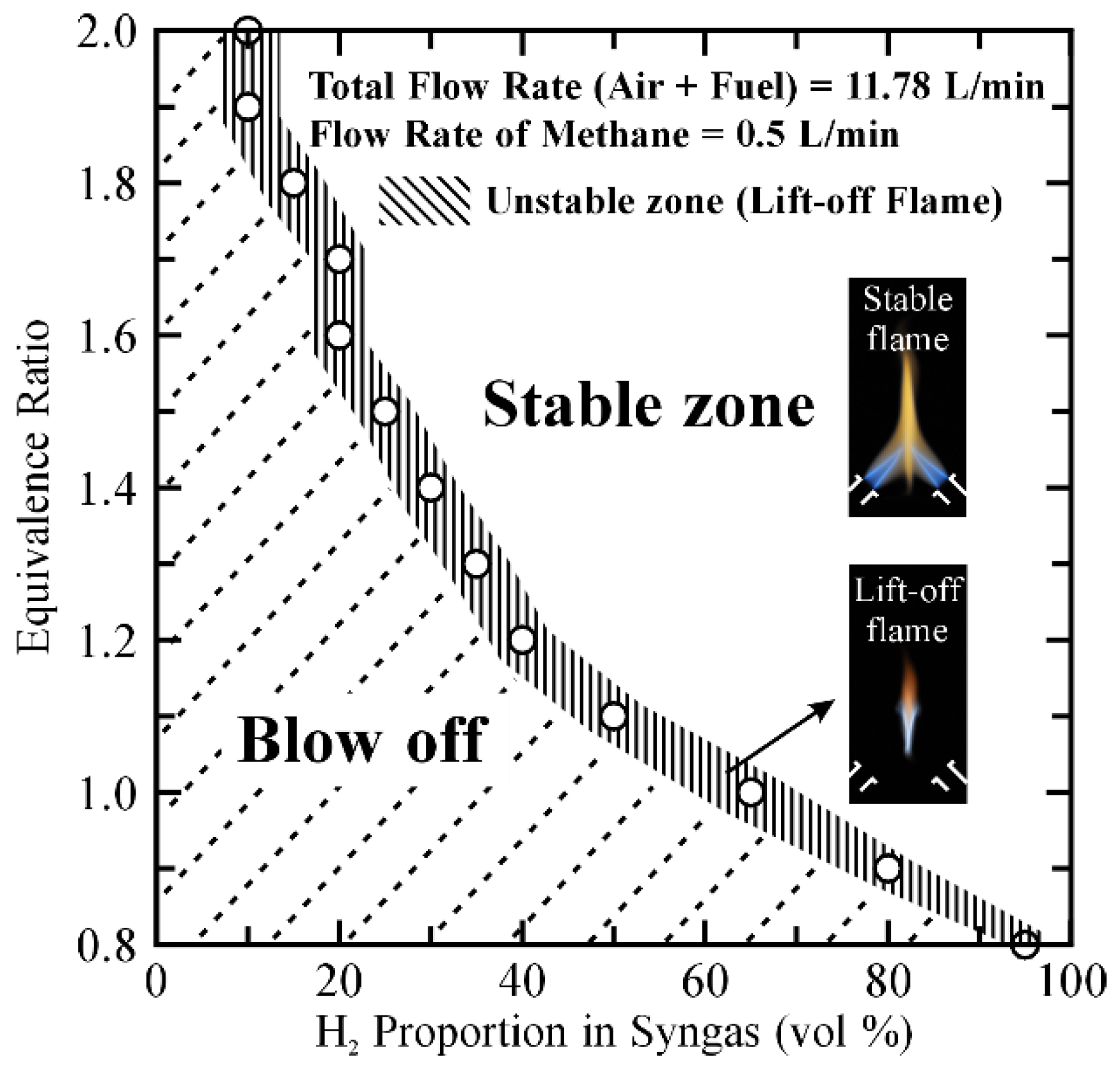
For industrial applications of syngas, the operating range and zone of stable combustion are important aspects. In this work, we recorded the operating range through the observation of flame patterns with a digital camera (Nikon D90, 4288 × 2848 pixels, Tokyo, Japan). We defined that a CH4/syngas/air premixed impinging flame was strongly anchored at the burner exit as a stable flame. The premixed impinging flame was first ignited to form a stable flame from H2/CO = 100/0 at each equivalence ratio (from φ = 0.8 to 2.0). For the examination of the operating range, we gradually modulated the H2/CO proportion of syngas from H2/CO = 100/0 to H2/CO = 0/100 until the CH4/syngas/air premixed impinging flame was blown off by the fuel jets. Figure 2 shows the operating range of this work. The oblique line represents the unstable zone (lift-off flame); the right and left sides of the oblique line represent the blow-off and the stable flame zone, respectively. In the unstable zone, we defined the lift-off flame as unstable because this flame appeared to jump up and down. The adjustment of the proportion of H2 in the unstable zone caused a CH4/syngas/air premixed impinging flame either to be sensitive to blow off or to be stable because of the highly reactive property of H2. The dotted line represents the blow-off zone in which a stable impinging flame was blown off by the fuel jets. The range of the stable zone expanded with an increased H2 proportion and the increased equivalence ratios because the increased content of H2 enhanced the flame speed [6,7]. The increased flame speed supported the impinging flame to resist the flow speed of the fuel jets so as to maintain a stable state. For this purpose, the demand of H2 content decreased with an increased equivalence ratio because the increased rate of volume flow of CO might also slightly enhance the entire flame speed [42].
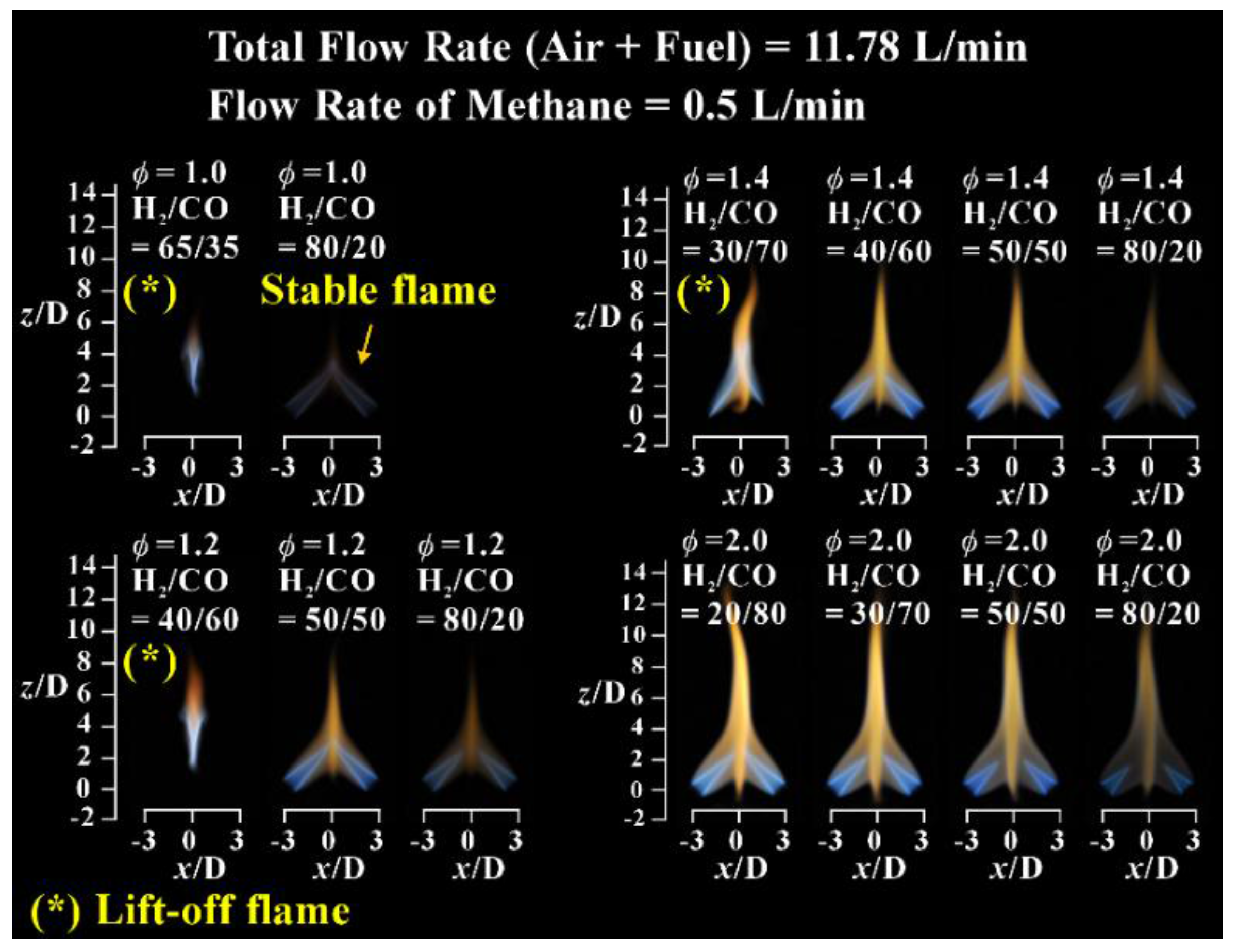
Figure 3 shows typical patterns of the CH4/syngas/air premixed impinging flame captured on plane xz. Table 2 and Table 3 present the fuel parameters for the photography of typical flame patterns. For a stable flame, the CH4/syngas/air premixed impinging flame was strongly anchored at the burner exit. The blue conical flame was surrounded by the outer orange flame, which was similar to a fuel-rich Bunsen flame. Two inclined flames impacted each other on the central axis and then merged into one flame. For an unstable flame, designated with symbol (*) in Figure 3, the impinging flame was blown away from the burner exit because the decreased H2 proportion caused the flame speed to be less than the flow speed; a large gap was generated between the flame root and the burner exit, likely resulting in heat loss and the escape of the unburned fuel.
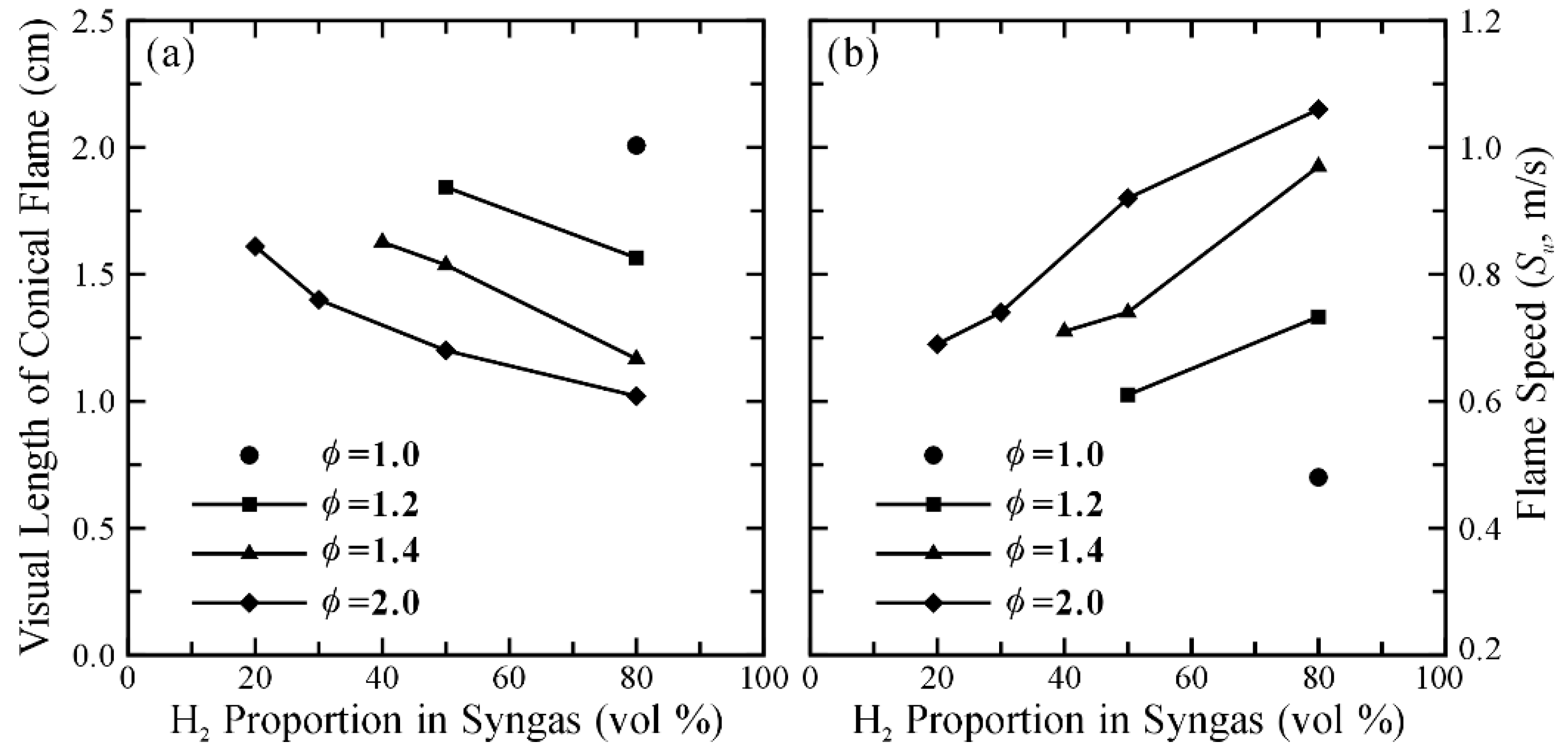
Figure 4 shows the visual length of a conical flame and the calculated laminar flame speed of stable flames corresponding to Figure 3. The visual length of a conical flame was measured directly from the flame images [32,43]. The laminar flame speed was calculated according to the Bunsen flame configuration [4] because the pattern of the conical flame was identical to that of a fuel-rich Bunsen flame. As Figure 4 shows, at a constant equivalence ratio with an increased proportion of H2, the length of a conical flame decreased, but the laminar flame speed increased. Such an increased proportion of H2 decreased the length of the conical flame because the increased flame speed altered the angle of the conical flame and its shape, which led to the separation of two conical flames as shown in Figure 3. The trends of flame speed and flame length agreed with previous work [32,43].
3.2. Flow Visualization, Distribution of Velocity and Vorticity in the Combustion Flow Field
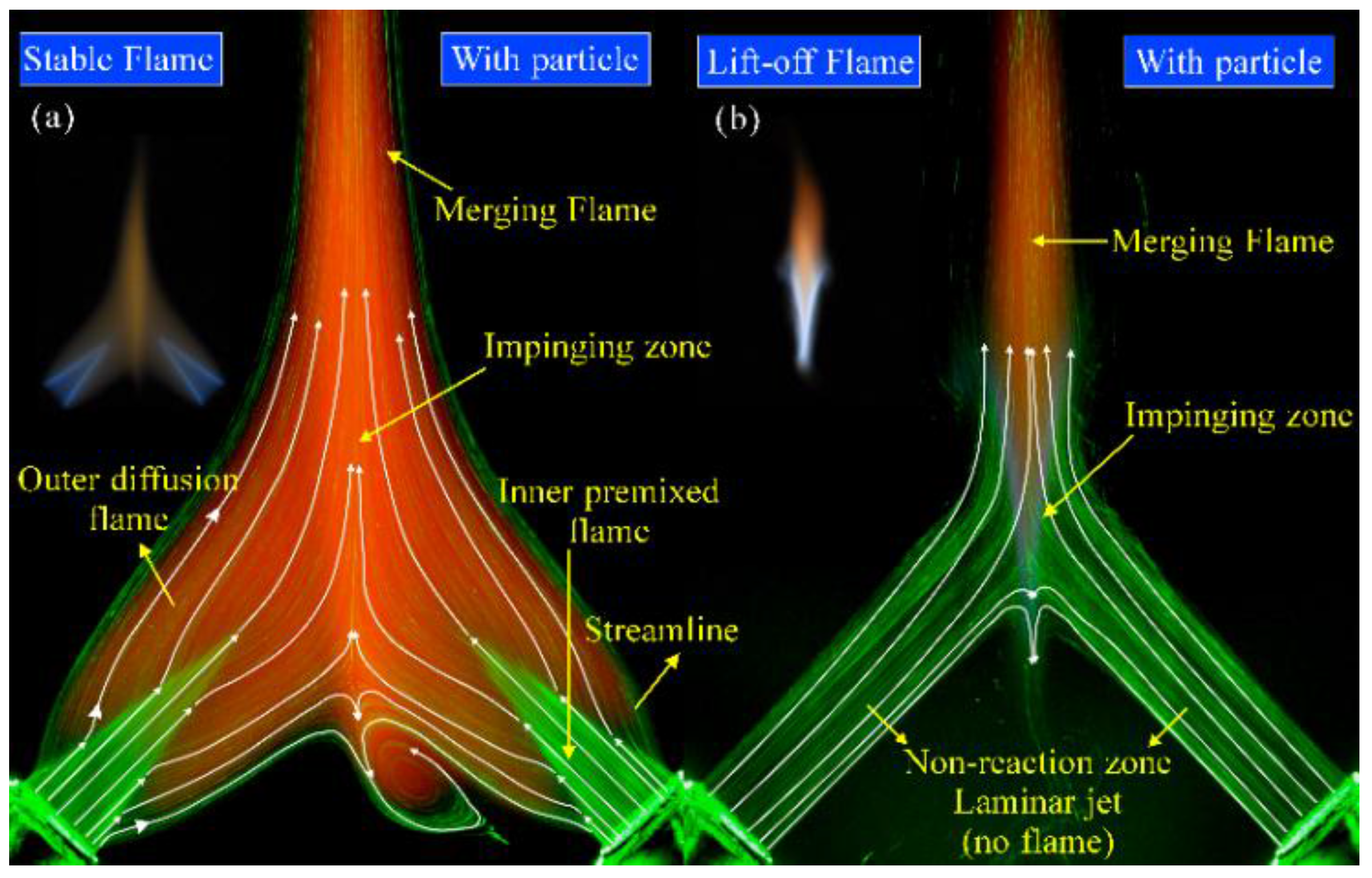
Figure 5 shows the combination of flame patterns and the corresponding flow visualization in the impinging flames, which clearly shows the structure of two impinging jets in the combustion flow field. In Figure 5a, the structure of the individual flame that has a dual flame structure is identical to a typical Bunsen flame, in which a fuel-rich inner flame is surrounded by a diffusion flame. The outer diffusion flame formed where the carbon monoxide and hydrogen products from the inner flame encountered the surrounding air [44]. In the stable flame, two fuel jets of premixed mixture penetrating the sheets of conical flame impacted each other in the impinging zone. In the unstable flame, Figure 5b, the flow structure above the burner exit was identical to that of a laminar non-reactive flow. The impinging flame was lifted above the burner exit by the two fuel jets. The flame front was forced to become suspended in the flow downstream, at which point the velocity of the flow was retarded by the impingement of two fuel jets.
Figure 6 shows the distribution of the turbulence intensity (T.I.) of a stable flame and a lift-off flame. The distribution of the turbulence intensity was calculated from the PIV measurement data with software (Insight 5, TSI) and Equation (6). In Figure 6, the turbulence intensities in the flow field of a stable flame and a lift-off flame both increased after the impingement of two fuel jets, in agreement with previous reports [20,24]. The heat transfer between the high-temperature products and the combustible fuel increased through the interaction of the flame and the flow, which facilitated the preheating of the unburned fuel [27].
u’ and v’ are the velocity fluctuations of the flow in directions u and v, respectively.
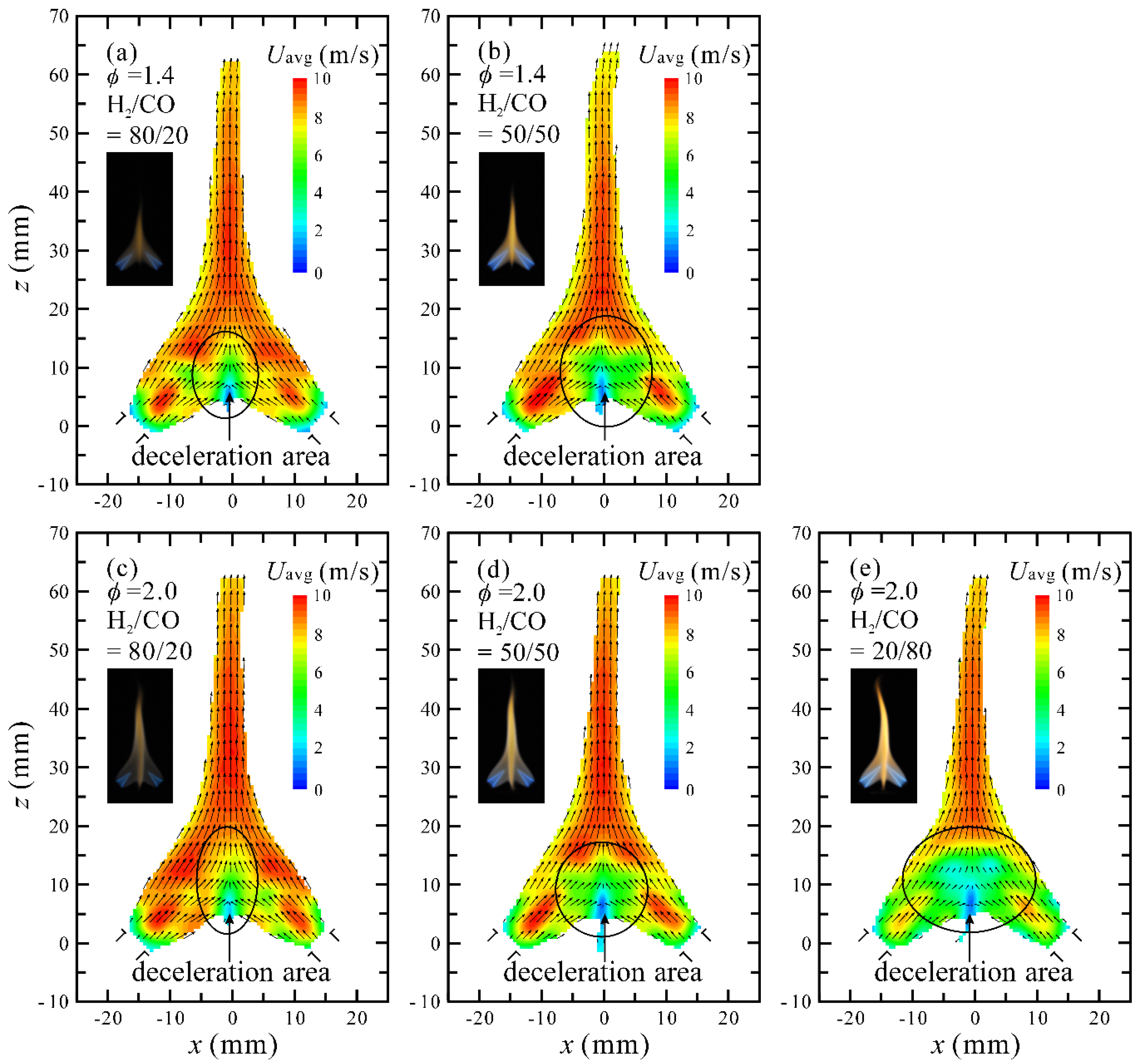
To examine how the varied H2/CO proportions affected the distribution of velocity and vorticity in the flow field of stable CH4/syngas/air premixed impinging flames, we applied non-intrusive particle-image velocimetry (frame rate 10,000 fps, resolution 512 × 512 pixels). Figure 7 shows the velocity distribution of the flow field in stable flames at φ = 1.4 and 2.0. An area of deceleration (green and light-blue contours in Figure 7) was formed in the flow field of the flame because of the mutual impingement of the two jet flows. According to previous reports concerning a counter-flow diffusion flame [45] and the counter-jet [46], a stagnation region exists in the counter flow. This stagnation region implies that the flow velocity decreased in this region after the jet impingement, which significantly influenced the flame characteristics and the flow structure [45,46]. In the deceleration area, the impingement of two jets increased the momentum transfer of the flow field, which enhanced the rate of fuel/air mixing [24]. The rate of reaction of an impinging flame might increase because of the increased mixing rate and the increased heat transfer. Furthermore, the deceleration area of flow fields of CH4/syngas/air premixed impinging flames expanded with an increased CO proportion, as shown in Figure 7a–e. The rates of mixing and reaction of CH4/syngas/air premixed impinging flames might increase with the increased proportion of CO because of the expanding area of deceleration when the CO proportion increased.
Figure 8 shows the vorticity distribution in stable flames at φ = 1.4 and 2.0. The intensity of the vorticity distribution at both φ = 1.4 and 2.0 increased with an increased CO proportion (a decreased H2 proportion). This finding about the vorticity distribution is similar to that of the jet-to-plate impinging flame; the great diffusivity of H2 led to vortical structures in the H2-rich flame weaker than in the H2-lean flame [31]. The increased intensity of vorticity enhanced the mixing of the flow [47], which means that the mixing rate of CH4/syngas/air premixed impinging flames increased when the proportion of CO increased.
3.3. Distribution of OH* Chemiluminescence
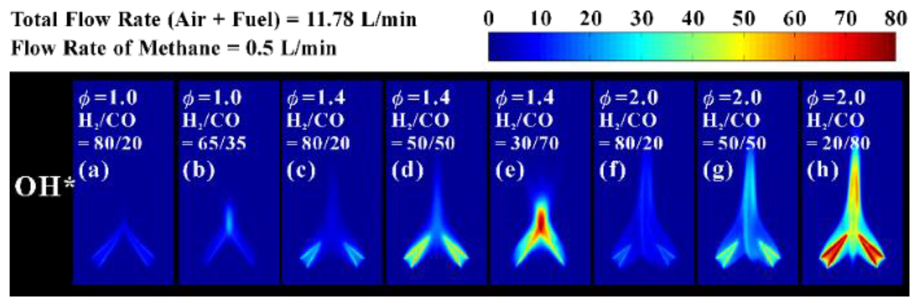
Figure 9 shows the distribution of OH* chemiluminescence corresponding to flame patterns of CH4/syngas/air premixed impinging flames with varied equivalence ratios and H2/CO proportions. The OH radicals concentrated both on the conical flame sheets and behind the impinging zone. The concentration of OH radicals behind the impinging zone indicated that most chain reactions of H atoms occurred not only on the flame sheets but also after the impingement of two fuel jets. This result verified that the rate of reaction of impinging flames increased because of the enhanced rate of mixing after the impingement of the two fuel jets. In Figure 9, the intensity of OH* chemiluminescence increases with increased CO proportion (φ = 1.0, 1.4 and 2.0), which means that CH4/syngas/air premixed impinging flames had greater rates of reaction and heat release when the CO proportion increased. This might relate to the CO oxidation and the variation of the deceleration area in the flow field. Since that area of the flow field expanded with increased CO proportion, the rate of fuel/air mixing of CH4/syngas/air premixed impinging flames increased. Hence, more O atoms were provided for the chain reaction of H atoms, and then this produced OH radicals as well as accelerating the CO reaction. The H atoms from the reaction CO + OH → CO2 + H were recycled in the chain reaction of H atoms and released more OH radicals [1,15]. The reaction rate of CO and the intensity of OH* chemiluminescence hence both increased with an increased CO proportion. According to the distribution of OH* chemiluminescence, we surmised that only a small amount of H2 in the syngas participated in the reaction, which is worthy of reference in terms of syngas burning on an impinging burner.
3.4. Temperature Distribution and CO Emission
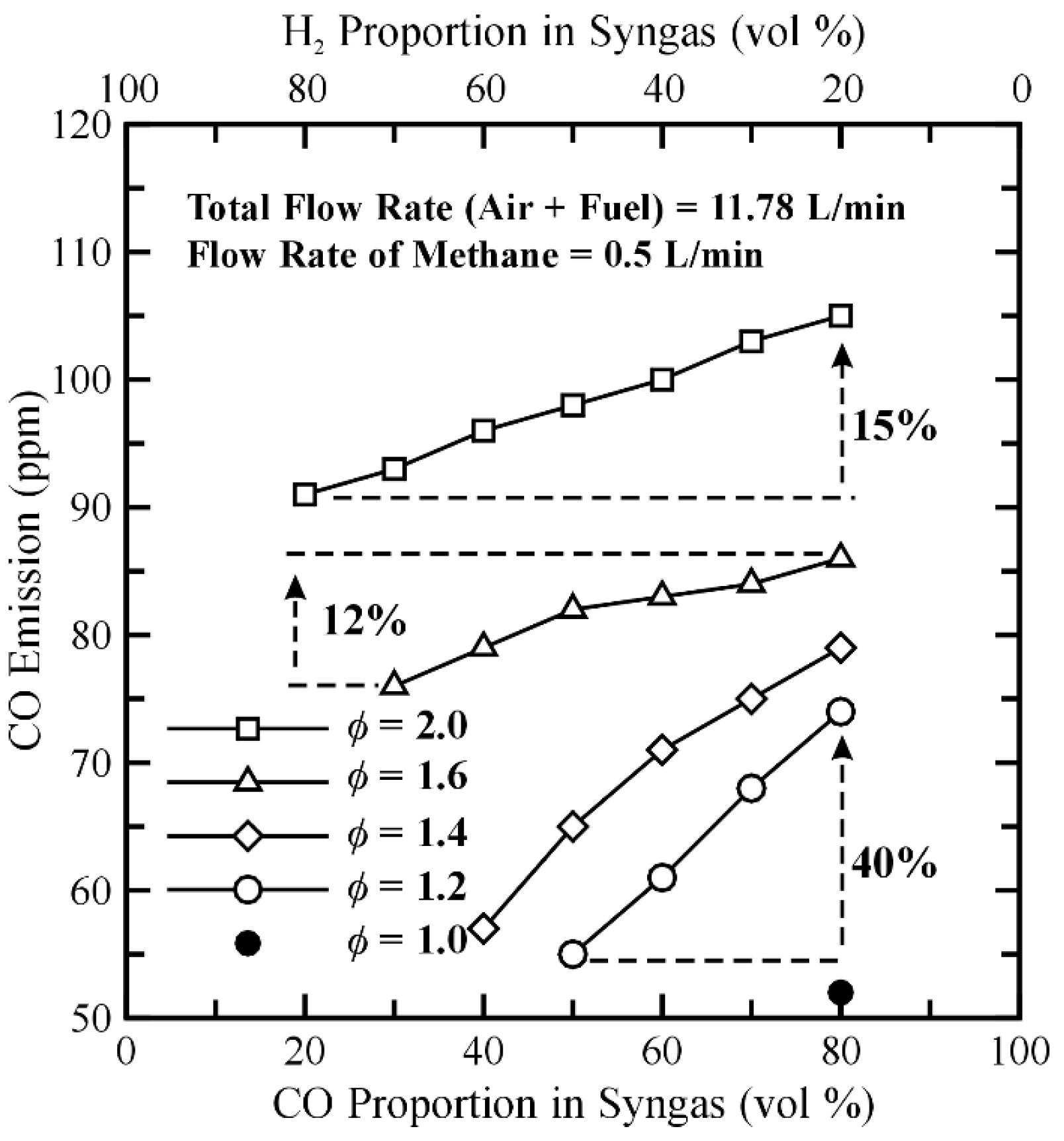
The CO emission of CH4/syngas/air premixed impinging flames might have great variation at the same examined conditions (equivalence ratio and total fuel volume flow rate) with a varied H2/CO proportion. The samples of exhaust gas were collected every 15 s for 150 s. Figure 10 shows the average CO emission from the stable flames of CH4/syngas/air premixed impinging flames; the CO emission of all the stable flames decreased with an increased H2 proportion at the same equivalence ratio because of the decreased CO proportion in the syngas. At a larger equivalence ratio, the CO emission from H2/CO = 80/20 to H2/CO = 20/80 increased by only 12% and 15%, such as φ = 1.6 and φ = 2.0, at which the provided volume flow rate of CO quadrupled. However, at a smaller equivalence ratio, the CO emission substantially increased by 35% and 40% from H2/CO = 80/20 to H2/CO = 20/80, such as φ = 1.2 and φ = 1.4. These results show that the CH4/syngas/air premixed impinging flames with large CO content did not emit a large CO exhaust at φ = 1.6 and φ = 2.0. The provided CO of syngas can readily participate in the reaction under the greater equivalence ratio because the large CO content in the fuel improved the rates of mixing and reaction of the CH4/syngas/air premixed impinging flames. Despite a large proportion of CO, its emission from CH4/syngas/air premixed impinging flames increased only slightly at large equivalence ratios. Under the fuel-lean condition, the CH4/syngas/air premixed impinging flame presented a lift-off flame (unstable) or tended to be blown-off (refer to Figure 2). For the present work, we expected that the CO emission would increase greatly when the CH4/syngas/air mixture combusted under a fuel-lean condition because the fuel mixture of a lift-off flame might leak to the ambient air from the flame root without combustion, hence increasing the CO emission in the fuel-lean combustion.
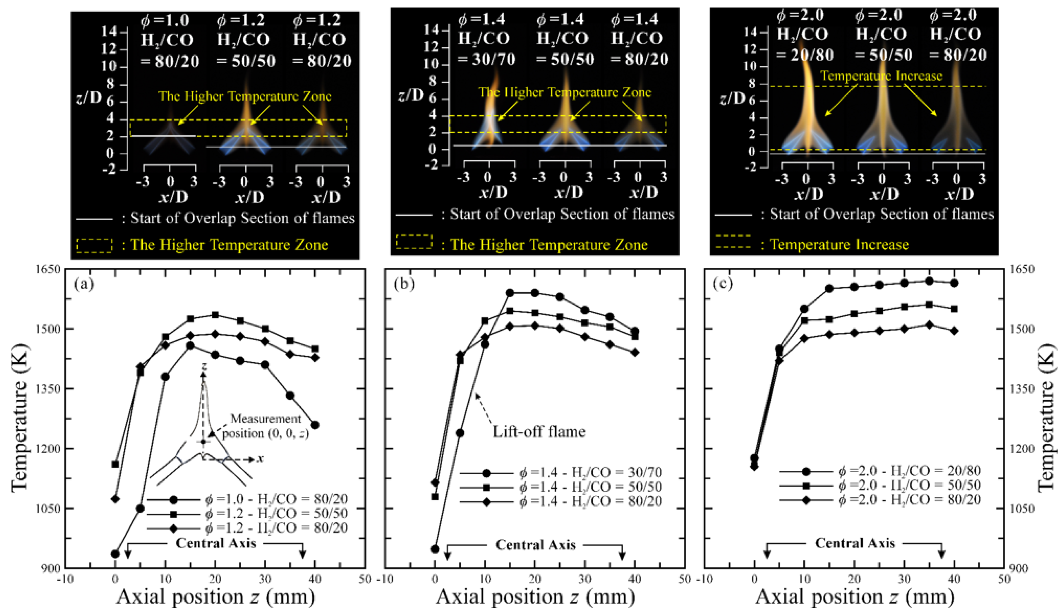
The temperature distribution along the centerline is an important feature of impinging flames because it is related to the extent of the reaction and the fuel/air mixing in the impinging zone. The axial temperatures were measured along the z-axis every 5 mm from the center point (0, 0, 0); the average temperature was calculated from 10 acquired data over a total sampling duration of 100 s. Figure 11 shows the temperature distribution along the central axis corresponding to a stable state of CH4/syngas/air premixed impinging flames with varied equivalence ratios and proportions of H2 and CO. The temperatures of the centerlines of CH4/syngas/air premixed impinging flames increased with an increased CO proportion at each equivalence ratio because of an increased rate of reaction of the CH4/syngas/air premixed impinging flames when the CO proportion increased. As the molar heating value of the reaction of CO is greater than that of H2 [1], an increased reaction of CO in the combustion increased the flame temperature. The zone of greater temperature in every impinging flame of this work was located behind the deceleration area. This result agrees with the temperature distribution of the centerline reported in the literature [24], which states that the lowest temperature was located at the impinging point and that the flame temperature increased after the impinging point of the two jets. For comparison, the temperature of the centerline of the pure methane diffusion impinging flame was below 1200 K [24]; in our work, the axial temperature of the CH4/syngas/air premixed impinging flames increased to 1435–1620 K, which indicates that the combustion performance of the CH4/syngas/air premixed impinging flames was superior to that of methane diffusion impinging flames.
4. Conclusions
In this study, we burned a fuel mixture of syngas and methane on an impinging burner, forming a CH4/syngas/air premixed impinging flame. This concept provided clean and efficient combustion for syngas applications. In our experimental investigation of the effects of varied proportions of H2 and CO on the fuel mixing and the reaction of CH4/syngas/air premixed impinging flames, we found that the varied proportions of H2 and CO in syngas caused a variation of the flow field of the flame, which is a crucial factor to affect the fuel mixing and reaction of CH4/syngas/air premixed impinging flames. The flow visualization and velocity distribution of the reactive flow field showed that a deceleration area of the main flow formed in the flow field because of the mutual impingement of the two jet flows; the momentum transfer was enhanced in this deceleration area so that the fuel/air mixing and flow intensity increased after the impingement of the two fuel jets. The deceleration area expanded and the intensity of the vorticity distribution increased with an increased proportion of CO, which indicated that the fuel/air mixing also increased with the increased proportion of CO.
The measured chemiluminescence of OH* was consistent with the discussion concerning the deceleration area in the combustion flow field. The OH* chemiluminescence showed that the produced OH radicals concentrated behind the impinging zone and that the intensity of OH* chemiluminescence increased with an increased CO proportion. These results show that the rates of mixing and reaction increased after the impingement of two fuel jets and that these rates increased with an increased proportion of CO; the section of the center line with the highest temperature in every impinging flame of this work was thus located behind the deceleration area. The temperature of the centerline also increased with increased CO proportion because of improved rates of mixing and reaction of the CH4/syngas/air premixed impinging flames when the CO proportion increased. The CO added to the syngas participated readily in the combustion with this impinging setup. Despite the syngas being provided with a large CO content, the CH4/syngas/air premixed impinging flames did not emit a large CO exhaust; the CO emission from H2/CO = 80/20 to H2/CO = 20/80 increased by only 12% and 15%, respectively, when the provided CO volume flow rate quadrupled. The results of this work are useful to improve the feasibility of a premixed impinging flame using syngas as a principal fuel.
Supplementary Materials
Supplementary materials can be found at www.mdpi.com/1996-1073/10/7/900/s1. Table S1. Combination parameters of blended fuel at a constant volume flow rate Vtotal = 11.78 L/min for typical flame patterns. Table S2. Volume concentration of each fuel in the entire fuel mixture.
Acknowledgments
The Ministry of Science and Technology of Taiwan, the Republic of China, supported this work under contract MOST 105-3113-F-002-003.
Author Contributions
The study concept was proposed by Chih-Pin Chiu and Jing-Tang Yang; Chih-Pin Chiu conducted the experiments and the data acquisition; Szu-I Yeh and Yu-Ching Tsai contributed tools for the analysis; Chih-Pin Chiu and Jing-Tang Yang analyzed the data; Chih-Pin Chiu wrote the manuscript; Szu-I Yeh and Yu-Ching Tsai edited this manuscript; and Jing-Tang Yang approved the final version of the manuscript.
Conflicts of Interest
The authors declare no conflict of interest.
Nomenclature
| D | inner diameter of the fuel tube, mm |
| μi | dynamic viscosity of component i, N s/m2 |
| Uexit | flow velocity at the burner exit, m/s |
| Yi | mole fraction of component i, % |
| Vtotal | volume flow rate of total gas, m3/s |
| Mi | molecular weight of component i, % |
| Re | Reynolds number of the mixture jet |
| ρi | density of component i, kg/m3 |
| ρmix | density of the mixture, kg/m3 |
| Vi | volume flow rate of component i, m3/s |
| μmix | dynamic viscosity of the mixture, N s/m2 |
| Xi | volume concentration of component i in entire fuel, % |
| T.I. | turbulence intensity, % |
| u’ | velocity fluctuation of in u direction, m/s |
| Su | laminar flame speed, m/s |
| v’ | velocity fluctuation of in v direction, m/s |
References
- Lieuwen, T.; Yang, V.; Yetter, R. Synthesis Gas Combustion: Fundamentals and Applications; CRC Press: Boca Raton, FL, USA, 2010. [Google Scholar]
- Wender, I. Reactions of synthesis gas. Fuel Process. Technol. 1996, 48, 189–297. [Google Scholar] [CrossRef]
- Kim, Y.S.; Lee, J.J.; Kim, T.S.; Sohn, J.L. Effects of syngas type on the operation and performance of a gas turbine in integrated gasification combined cycle. Energy Convers. Manag. 2011, 52, 2262–2271. [Google Scholar] [CrossRef]
- Bouvet, N.; Chauveau, C.; Gökalp, I.; Lee, S.Y.; Santoro, R. Characterization of syngas laminar flames using the Bunsen burner configuration. Int. J. Hydrogen Energy 2011, 36, 992–1005. [Google Scholar] [CrossRef]
- Zhang, Y.; Shen, W.; Fan, M.; Zhang, H.; Li, S. Laminar flame speed studies of lean premixed H2/CO/air flames. Combust. Flame 2014, 161, 2492–2495. [Google Scholar] [CrossRef]
- Yasiry, A.S.; Shahad, H.A. An experimental study of the effect of hydrogen blending on burning velocity of LPG at elevated pressure. Int. J. Hydrogen Energy 2016, 41, 19269–19277. [Google Scholar] [CrossRef]
- Lee, H.; Jiang, L.; Mohamad, A. A review on the laminar flame speed and ignition delay time of Syngas mixtures. Int. J. Hydrogen Energy 2014, 39, 1105–1121. [Google Scholar] [CrossRef]
- Kéromnès, A.; Metcalfe, W.K.; Heufer, K.A.; Donohoe, N.; Das, A.K.; Sung, C.J. An experimental and detailed chemical kinetic modeling study of hydrogen and syngas mixture oxidation at elevated pressures. Combust. Flame 2013, 160, 995–1011. [Google Scholar] [CrossRef]
- Varga, T.; Nagy, T.; Olm, C.; Zsély, I.G.; Pálvölgyi, R.; Valkó, É. Optimization of a hydrogen combustion mechanism using both direct and indirect measurements. Proc. Combust. Inst. 2015, 35, 589–596. [Google Scholar] [CrossRef]
- Wang, J.; Zhang, M.; Huang, Z.; Kudo, T.; Kobayashi, H. Measurement of the instantaneous flame front structure of syngas turbulent premixed flames at high pressure. Combust. Flame 2013, 160, 2434–2441. [Google Scholar] [CrossRef]
- Jin, W.; Wang, J.; Nie, Y.; Yu, S.; Huang, Z. Experimental study on flame instabilities of laminar premixed CH4/H2/air non-adiabatic flat flames. Fuel 2015, 159, 599–606. [Google Scholar] [CrossRef]
- Law, C.K.; Kwon, O. Effects of hydrocarbon substitution on atmospheric hydrogen–air flame propagation. Int. J. Hydrogen Energy 2004, 29, 867–879. [Google Scholar] [CrossRef]
- Chen, J.W.; Chiu, C.P.; Mo, S.H.; Yang, J.T. Combustion characteristics of premixed propane flame with added H2 and CO on a V-shaped impinging burner. Int. J. Hydrogen Energy 2015, 40, 1244–1255. [Google Scholar] [CrossRef]
- Wang, J.; Wei, Z.; Yu, S.; Jin, W.; Xie, Y.; Zhang, M. Effects of stretch and preferential diffusion on tip opening of laminar premixed Bunsen flames of syngas/air mixtures. Fuel 2015, 148, 1–8. [Google Scholar] [CrossRef]
- Law, C.K. Combustion Physics; Cambridge University Press: New York, USA, 2010. [Google Scholar]
- Mueller, M.; Yetter, R.; Dryer, F. Flow reactor studies and kinetic modeling of the H2/O2/NOx and CO/H2O/O2/NOx reactions. Int. J. Chem. Kinet. 1999, 31, 705–724. [Google Scholar] [CrossRef]
- Wu, C.Y.; Chao, Y.C.; Cheng, T.; Chen, C.P.; Ho, C.T. Effects of CO addition on the characteristics of laminar premixed CH4/air opposed-jet flames. Combust. Flame 2009, 156, 362–373. [Google Scholar] [CrossRef]
- Nosseir, N.; Peled, U.; Hildebrand, G. Pressure field generated by jet-on-jet impingement. AIAA J. 1987, 25, 1312–1317. [Google Scholar] [CrossRef]
- Disimile, P.; Savory, E.; Toy, N. Mixing characteristics of twin impinging circular jets. J. Propul. Power 1995, 11, 1118–1124. [Google Scholar] [CrossRef]
- Rho, B.J.; Kim, J.K.; Dwyer, H.A. Experimental study of a turbulent cross jet. AIAA J. 1990, 28, 784–789. [Google Scholar] [CrossRef]
- Elangovan, S.; Solaiappan, A.; Rathakrishnan, E. Studies on twin non-parallel unventilated axisymmetric jets. Proc. Inst. Mech. Eng. G J. Aerosp. Eng. 1996, 210, 309–321. [Google Scholar] [CrossRef]
- Landers, B.D.; Disimile, P.J. The Growth Characteristics of Transient Impinging Axisymmetric Turbulent Jets. J. Flow Visual. Image Process. 2015, 22, 117–129. [Google Scholar] [CrossRef]
- Landers, B.D. Mixing Characteristics of Turbulent Twin Impinging Axisymmetric Jets at Various Impingement Angles. Master’s Thesis, University of Cincinnati, Cincinnati, OH, USA, 2016. [Google Scholar]
- Su, A.; Liu, Y.C. Investigation of impinging diffusion flames with inert gas. Int. J. Heat Mass Transf. 2002, 45, 3251–3257. [Google Scholar] [CrossRef]
- Boushaki, T.; Sautet, J.C. Characteristics of flow from an oxy-fuel burner with separated jets: Influence of jet injection angle. Exp. Fluids 2010, 48, 1095–1108. [Google Scholar] [CrossRef]
- Boushaki, T.; Guessasma, S.; Sautet, J.C. Predictive analysis of combined burner parameter effects on oxy-fuel flames. Appl. Therm. Eng. 2011, 31, 202–212. [Google Scholar] [CrossRef]
- Li, C.C.; Chen, J.W.; Yang, J.T. Stabilization of double flames interacting with the intersecting flow on a V-shaped burner. Combust. Sci. Technol. 2012, 184, 2117–2135. [Google Scholar] [CrossRef]
- Dinesh, K.R.; Jiang, X.; van Oijen, J.A. Hydrogen-enriched non-premixed jet flames: Analysis of the flame surface, flame normal, flame index and Wobbe index. Int. J. Hydrogen Energy 2014, 39, 6753–6763. [Google Scholar] [CrossRef]
- Dinesh, K.R.; van Oijen, J.A.; Luo, K.H.; Jiang, X. Nitric oxide pollutant formation in high hydrogen content (HHC) syngas flames. Int. J. Hydrogen Energy 2015, 40, 13621–13634. [Google Scholar] [CrossRef]
- Dinesh, K.R.; Jiang, X.; van Oijen, J.A. Hydrogen-enriched non-premixed jet flames: Compositional structures with near-wall effects. Int. J. Hydrogen Energy 2013, 38, 5150–5164. [Google Scholar] [CrossRef]
- Dinesh, K.R.; Jiang, X.; van Oijen, J.A.; Bastiaans, R.J.M.; de Goey, L.P.H. Influence of fuel variability on the characteristics of impinging non-premixed syngas burning. Proc. Combust. Inst. 2013, 34, 3219–3229. [Google Scholar] [CrossRef]
- Zhen, H.S.; Leung, C.W.; Cheung, C.S.; Huang, Z.H. Characterization of biogas-hydrogen premixed flames using Bunsen burner. Int. J. Hydrogen Energy 2014, 39, 13292–13299. [Google Scholar] [CrossRef]
- Pan, K.L.; Li, C.C.; Juan, W.C.; Yang, J.T. Low-frequency oscillation of a non-premixed flame on a bluff-body burner. Combust. Sci. Technol. 2009, 181, 1217–1230. [Google Scholar] [CrossRef]
- Raffel, M.; Willert, C.E.; Wereley, S.; Kompenhans, J. Particle Image Velocimetry: A Practical Guide; Springer: New York, NY, USA, 2013. [Google Scholar]
- Ballester, J.; García-Armingol, T. Diagnostic techniques for the monitoring and control of practical flames. Prog. Energy Combust. Sci. 2010, 36, 375–411. [Google Scholar] [CrossRef]
- Kaskan, W. The dependence of flame temperature on mass burning velocity. Symp. Int. Combust. 1957, 6, 134–143. [Google Scholar] [CrossRef]
- Hindasageri, V.; Vedula, R.; Prabhu, S. Thermocouple error correction for measuring the flame temperature with determination of emissivity and heat transfer coefficient. Rev. Sci. Instrum. 2013, 84, 024902. [Google Scholar] [CrossRef] [PubMed]
- Samiran, N.A.; Ng, J.H.; Jaafar, M.N.M.; Valera-Medina, A.; Chong, C.T. H2-rich syngas strategy to reduce NOx and CO emissions and improve stability limits under premixed swirl combustion mode. Int. J. Hydrogen Energy 2016, 41, 19243–19255. [Google Scholar] [CrossRef]
- Lee, I.B.; Woo, I.S.; Lee, M.C. Effects of nitrogen dilution on the NOx and CO emission of H2/CO/CH4 syngases in a partially-premixed gas turbine model combustor. Int. J. Hydrogen Energy 2016, 41, 15841–15851. [Google Scholar] [CrossRef]
- Zhen, H.; Leung, C.; Cheung, C. Emission of impinging swirling and non-swirling inverse diffusion flames. Appl. Energy 2011, 88, 1629–1634. [Google Scholar] [CrossRef]
- Moffat, R.J. Contributions to the theory of single-sample uncertainty analysis. J. Fluids Eng. 1982, 104, 250–260. [Google Scholar] [CrossRef]
- Dong, C.; Zhou, Q.; Zhao, Q.; Zhang, Y.; Xu, T.; Hui, S. Experimental study on the laminar flame speed of hydrogen/carbon monoxide/air mixtures. Fuel 2009, 88, 1858–1863. [Google Scholar] [CrossRef]
- Zhen, H.; Leung, C.; Cheung, C. A comparison of the heat transfer behaviors of biogas–H2 diffusion and premixed flames. Int. J. Hydrogen Energy 2014, 39, 1137–1144. [Google Scholar] [CrossRef]
- Turns, S.R. An Introduction to Combustion, 2nd ed.; McGraw-Hill: New York, NY, USA, 2006; pp. 256–257. [Google Scholar]
- Tsuji, H.; Yamaoka, I. The counterflow diffusion flame in the forward stagnation region of a porous cylinder. Symp. Int. Combust. 1967, 11, 979–984. [Google Scholar] [CrossRef]
- Rolon, J.C.; Veynante, D.; Martin, J.P.; Durst, F. Counter jet stagnation flows. Exp. Fluids 1991, 11, 313–324. [Google Scholar] [CrossRef]
- Waitz, I.A.; Qiu, Y.J.; Manning, T.A.; Fung, A.K.S.; Elliot, J.K.; Kerwin, J.M.; Marble, F.E. Enhanced mixing with streamwise vorticity. Prog. Aerospace Sci. 1997, 33, 323–351. [Google Scholar] [CrossRef]
Figure 1.
Schematic diagram of the experimental setup (a) Schematic description of burner, fuel supply, and image-acquisition system; (b) multi-jet inclined injection burner; (c) reference coordinate system; (d) system for analysis of exhaust.
Figure 1.
Schematic diagram of the experimental setup (a) Schematic description of burner, fuel supply, and image-acquisition system; (b) multi-jet inclined injection burner; (c) reference coordinate system; (d) system for analysis of exhaust.

Figure 2.
Operating range of a CH4/syngas/air premixed impinging flame at φ = 0.8 to 2.0 with a constant total volume flow rate Qtotal = 11.78 L/min and a constant methane volume flow rate Qmethane = 0.5 L/min.
Figure 2.
Operating range of a CH4/syngas/air premixed impinging flame at φ = 0.8 to 2.0 with a constant total volume flow rate Qtotal = 11.78 L/min and a constant methane volume flow rate Qmethane = 0.5 L/min.

Figure 3.
Typical flame patterns of the CH4/syngas/air premixed impinging flame.

Figure 4.
(a) Visual length of the conical flame and (b) calculated laminar flame speed of the stable CH4/syngas/air premixed impinging flame with varied H2/CO proportion.
Figure 4.
(a) Visual length of the conical flame and (b) calculated laminar flame speed of the stable CH4/syngas/air premixed impinging flame with varied H2/CO proportion.

Figure 5.
Direct photographs of the combination of flame pattern and the corresponding flow visualization: (a) stable flame; (b) unstable flame of a CH4/syngas/air premixed impinging flame.
Figure 5.
Direct photographs of the combination of flame pattern and the corresponding flow visualization: (a) stable flame; (b) unstable flame of a CH4/syngas/air premixed impinging flame.

Figure 6.
Distribution of turbulence intensity of (a) a stable flame; (b) an unstable flame of a CH4/syngas/air premixed impinging flame.
Figure 6.
Distribution of turbulence intensity of (a) a stable flame; (b) an unstable flame of a CH4/syngas/air premixed impinging flame.
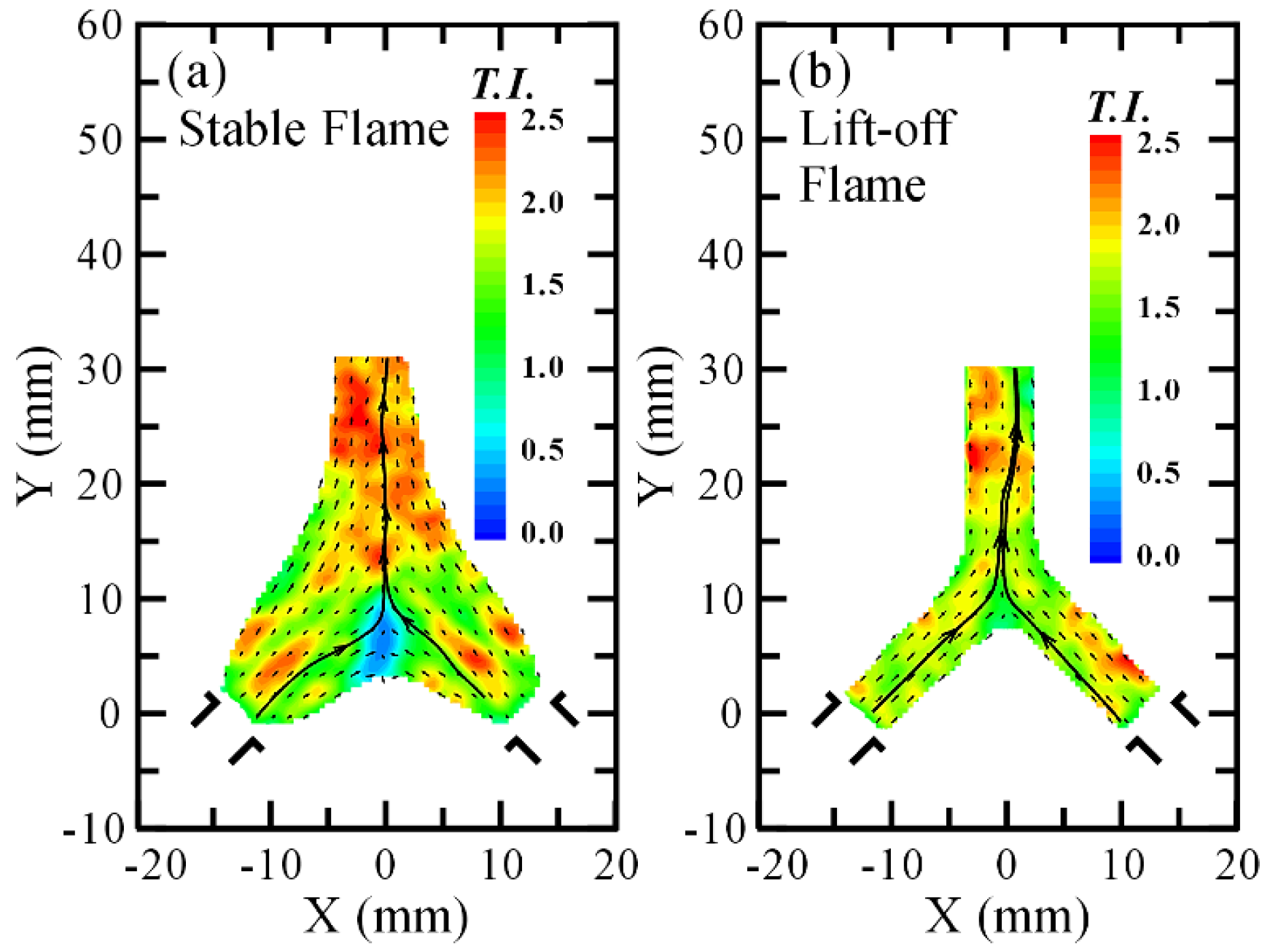
Figure 7.
Velocity distributions of CH4/syngas/air premixed impinging flames: (a) φ = 1.4 and H2/CO = 80/20; (b) φ = 1.4 and H2/CO = 50/50; (c) φ = 2.0 and H2/CO = 80/20; (d) φ = 2.0 and H2/CO = 50/50; (e) φ = 2.0 and H2/CO = 20/80.
Figure 7.
Velocity distributions of CH4/syngas/air premixed impinging flames: (a) φ = 1.4 and H2/CO = 80/20; (b) φ = 1.4 and H2/CO = 50/50; (c) φ = 2.0 and H2/CO = 80/20; (d) φ = 2.0 and H2/CO = 50/50; (e) φ = 2.0 and H2/CO = 20/80.

Figure 8.
Velocity distribution of CH4/syngas/air premixed impinging flames: (a) φ = 1.4 and H2/CO = 80/20; (b) φ = 1.4 and H2/CO = 50/50; (c) φ = 2.0 and H2/CO = 80/20; (d) φ = 2.0 and H2/CO = 20/80.
Figure 8.
Velocity distribution of CH4/syngas/air premixed impinging flames: (a) φ = 1.4 and H2/CO = 80/20; (b) φ = 1.4 and H2/CO = 50/50; (c) φ = 2.0 and H2/CO = 80/20; (d) φ = 2.0 and H2/CO = 20/80.
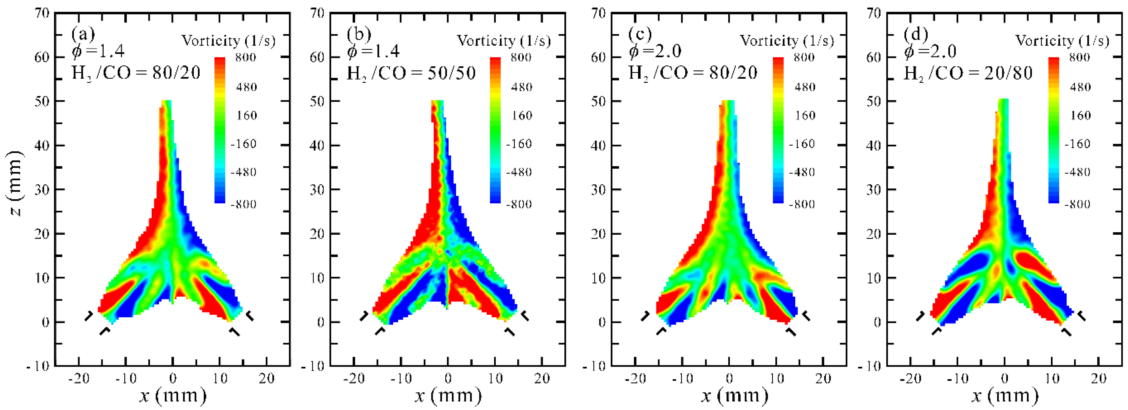
Figure 9.
Distribution of OH* chemiluminescence in CH4/syngas/air premixed impinging flames with varied equivalence ratios and H2/CO proportions.
Figure 9.
Distribution of OH* chemiluminescence in CH4/syngas/air premixed impinging flames with varied equivalence ratios and H2/CO proportions.

Figure 10.
CO emission of CH4/syngas/air premixed impinging flames with varied equivalence ratios and H2/CO proportions.
Figure 10.
CO emission of CH4/syngas/air premixed impinging flames with varied equivalence ratios and H2/CO proportions.

Figure 11.
Distribution of axial temperature of CH4/syngas/air premixed impinging flames: (a) φ= 1.0 and 1.2; (b) φ = 1.4; (c) φ = 2.0.
Figure 11.
Distribution of axial temperature of CH4/syngas/air premixed impinging flames: (a) φ= 1.0 and 1.2; (b) φ = 1.4; (c) φ = 2.0.

Table 1.
Setup of experimental parameters.
| Constant Parameters | Given Parameters | Variation Parameters |
|---|---|---|
| Total volume flow rate, Vtotal = 11.78 L/min | equivalence ratio, φ from 0.8 to 2.0 | Volume concentration of component i in entire fuel, Xi, % |
| CH4 volume flow rate, Vmethane = 0.5 L/min | H2/CO proportion 1 from 100/0 to 0/100 | H2 volume flow rate, VHydrogen |
| Flow velocity of burner exit, Uexit = 5.0 m/s | - | CO volume flow rate, VCarbon monoxide |
1 Proportion of volume flow rate in syngas.
Table 2.
Combination parameters of blended fuel at a constant volume flow rate Vtotal = 11.78 L/min for typical flame patterns.
Table 2.
Combination parameters of blended fuel at a constant volume flow rate Vtotal = 11.78 L/min for typical flame patterns.
| Vair (L/min) | Vmethane (L/min) | VHydrogen (L/min) | VCarbon monoxide (L/min) | H2/CO (Syngas) | φ | Re |
|---|---|---|---|---|---|---|
| 9.35 | 0.50 | 1.25 | 0.68 | 65/35 | 1.0 | 1622 |
| 9.35 | 0.50 | 1.54 | 0.39 | 80/20 | 1.0 | 1602 |
| 8.83 | 0.50 | 0.98 | 1.47 | 40/60 | 1.2 | 1636 |
| 8.83 | 0.50 | 1.23 | 1.23 | 50/50 | 1.2 | 1620 |
| 8.83 | 0.50 | 1.96 | 0.49 | 80/20 | 1.2 | 1571 |
| 8.36 | 0.50 | 0.88 | 2.04 | 30/70 | 1.4 | 1640 |
| 8.36 | 0.50 | 1.17 | 1.75 | 40/60 | 1.4 | 1621 |
| 8.36 | 0.50 | 1.46 | 1.46 | 50/50 | 1.4 | 1602 |
| 8.36 | 0.50 | 2.33 | 0.58 | 80/20 | 1.4 | 1542 |
| 7.21 | 0.50 | 0.81 | 3.25 | 20/80 | 2.0 | 1637 |
| 7.21 | 0.50 | 1.22 | 2.84 | 30/70 | 2.0 | 1611 |
| 7.21 | 0.50 | 2.03 | 2.03 | 50/50 | 2.0 | 1556 |
| 7.21 | 0.50 | 3.25 | 0.81 | 80/20 | 2.0 | 1464 |
Table 3.
Volume concentration of each fuel in the entire fuel mixture.
| φ | H2/CO (Syngas) | Xmethane (vol %) (in Total Fuel) | XHydrogen (vol %) (in Total Fuel) | XCarbon monoxide (vol %) (in Total Fuel) |
|---|---|---|---|---|
| 1.0 | 65/35 | 20.60 | 51.44 | 27.96 |
| 1.0 | 80/20 | 20.60 | 63.37 | 16.03 |
| 1.2 | 40/50 | 16.95 | 33.22 | 49.83 |
| 1.2 | 50/50 | 16.95 | 41.55 | 41.50 |
| 1.2 | 80/20 | 16.95 | 66.44 | 16.61 |
| 1.4 | 30/70 | 14.63 | 25.73 | 59.64 |
| 1.4 | 40/60 | 14.63 | 34.21 | 51.16 |
| 1.4 | 50/50 | 14.63 | 42.69 | 42.68 |
| 1.4 | 80/20 | 14.63 | 68.33 | 17.04 |
| 2.0 | 20/80 | 10.96 | 17.76 | 71.28 |
| 2.0 | 30/70 | 10.96 | 26.75 | 62.29 |
| 2.0 | 50/50 | 10.96 | 44.52 | 44.52 |
| 2.0 | 80/20 | 10.96 | 71.27 | 17.77 |
© 2017 by the authors. Licensee MDPI, Basel, Switzerland. This article is an open access article distributed under the terms and conditions of the Creative Commons Attribution (CC BY) license (http://creativecommons.org/licenses/by/4.0/).
Share and Cite
MDPI and ACS Style
Chiu, C.-P.; Yeh, S.-I.; Tsai, Y.-C.; Yang, J.-T. An Investigation of Fuel Mixing and Reaction in a CH4/Syngas/Air Premixed Impinging Flame with Varied H2/CO Proportion. Energies 2017, 10, 900. https://doi.org/10.3390/en10070900
AMA Style
Chiu C-P, Yeh S-I, Tsai Y-C, Yang J-T. An Investigation of Fuel Mixing and Reaction in a CH4/Syngas/Air Premixed Impinging Flame with Varied H2/CO Proportion. Energies. 2017; 10(7):900. https://doi.org/10.3390/en10070900
Chicago/Turabian StyleChiu, Chih-Pin, Szu-I Yeh, Yu-Ching Tsai, and Jing-Tang Yang. 2017. "An Investigation of Fuel Mixing and Reaction in a CH4/Syngas/Air Premixed Impinging Flame with Varied H2/CO Proportion" Energies 10, no. 7: 900. https://doi.org/10.3390/en10070900
Note that from the first issue of 2016, this journal uses article numbers instead of page numbers. See further details here.