Thermo-Fluidic Comparison between Sandwich Panels with Tetrahedral Lattice Cores Fabricated by Casting and Metal Sheet Folding


1
Air-Breathing Hypersonic Technology Research Centre, China Aerodynamics Research and Development Centre, Mianyang 621000, China
2
School of Mechanical Engineering, Northwestern Polytechnical University, Xi’an 710072, China
3
School of Marine Science and Technology, Northwestern Polytechnical University, Xi’an 710072, China
*
Author to whom correspondence should be addressed.
Energies 2017, 10(7), 906; https://doi.org/10.3390/en10070906
Submission received: 15 May 2017
/
Revised: 5 June 2017
/
Accepted: 26 June 2017
/
Published: 2 July 2017
(This article belongs to the Section I: Energy Fundamentals and Conversion)
Abstract
:This numerical study compares single-phase forced convective heat transfer between two sandwich panels with tetrahedral metallic lattice cores separately fabricated by investment casting and the more cost-effective metal sheet folding method. The numerical model is validated against available experimental data. For a given Reynolds number and core porosity, the results reveal that the brazed sandwich outperforms the casted sandwich, exhibiting a 13% to 16% higher Nusselt number. Bigger vertexes and more evident blockage of mainstream by the ligaments are found to intensify the horseshoe vortex and the counter-rotating vortex pair upstream and downstream of each vertex. Relative to the casted sandwich panel, therefore, endwall heat transfer is enhanced by 22% to 27%, while similar heat transfer is achieved on the ligaments. It is also found that, for a given Reynolds number, the brazed sandwich induces a 1.6 to 1.7 times higher pressure drop relative to the casted sandwich due to more severe flow separation caused by the sharp edges of the rectangular ligaments. Finally, for a given pumping power, both sandwiches provide a similar heat transfer performance. Given that the brazed sandwich is more cost-effective and easier to fabricate than the casted one, the former may be superior from an engineering application point of view.
1. Introduction
Thermal management is necessary for many energy systems to eliminate overheating or maintain a specified temperature. In some applications such as the cooling of electronic devices in a personal desktop, heat dissipation is the only function of the heat sink [1,2]. However, for the active cooling of some other equipment, e.g., combustion chambers of hypersonic vehicles and jet blast deflectors of aircraft carriers, etc. [3,4,5,6,7], the cooling modules, usually in the form of sandwich panels, are required to be lightweight and able to sustain severe thermal and mechanical loads concurrently. For these situations, periodic cellular materials (PCMs) like those shown in Figure 1 are promising heat dissipation cores configured in the sandwich cooling channels [3,5,6,7,8,9]. Many studies have revealed that PCMs have high specific strength/stiffness and therefore are lightweight [9]; additionally, their open topologies with 29 high specific surface area endow them with excellent heat dissipation capabilities [9]. In view of these advantages, great efforts have been devoted to the development of cost-effective and design friendly PCMs and to characterization of their mechanical/thermal performance.
During the past decades, PCMs with various topologies, like those shown in Figure 1, have been devised [10,11,12,13,14,15]. The corresponding fabrication methods include investment casting [16], metal sheet folding [10,17,18], metal wire weaving [14], etc., which exhibit different limitations. For investment casting, a prototype polymer sample should first be fabricated by using rapid prototyping, which is finally gasified; the parent metal material should have excellent casting properties to minimize the flaws of the resultant lattice. Therefore, the fabrication process is complex and expensive [16]. For metal wire weaving, helical metal wires should first be manufactured by using parent materials with excellent plasticity; at present, the weaving process for complex topologies is still artificial and cannot be finished by a machine [14]. For the metal sheet folding, a perforated or expanded metal sheet is fabricated first based on the target topology, followed by automatic folding of the sheet. In view of the above, metal sheet folding is considered to be simpler, more cost-effective, and suitable for volume production by automatic production lines [18].
The development of PCMs with the aid of the aforementioned fabrication methods is always accompanied by the characterization of their thermal and mechanical behaviors. For the former aspect, as the concern of the present study, many studies have been reported. By using experiments and numerical simulations, the pioneering work by Kim et al. [19,20,21,22] thoroughly investigated both the overall and detailed flow and heat transfer mechanisms of a casted tetrahedral metallic lattice, as shown in Figure 1. Gao et al. [23,24] introduced a composite tetrahedral lattice and explored its thermal performance for electronics cooling; relevant analytical models were developed for engineering design. Hoffmann et al. [12] experimentally investigated the thermo-fluidic characteristics of a casted Kagome metallic lattice; they found that the orientation of the lattice relative to the flow direction has an evident effect on both pressure drop and heat transfer. Joo et al. [25] and Feng et al. [5] explored the heat transfer characteristics of a wire-woven bulk Kagome (WBK) lattice; they found that WBK thermally outperforms the casted Kagome lattice for a given porosity. Zhao et al. [26] developed a woven lattice by orthogonally weaving copper wires; the effects of the weaving pattern and flow configurations on its thermal performance were investigated. Yan et al. [18] presented a thorough study of an X-type metallic lattice by using both experiments and numerical simulations; for a given porosity, it was found that the overall thermal performance of the lattice is superior relative to other reference lattices.
It has been well established by the aforementioned studies that the morphology of a PCM has an evident effect on its thermal performance. For casted and woven lattices, the ligaments have a circular cross-section; the variation of surface area density will definitely lead to a different porosity. For lattices fabricated by the metal sheet folding method, at a given porosity, the surface area density can be easily changed by changing the aspect ratio of the rectangular ligament cross-section. It is therefore believed that differences in the cross-sections of the ligaments will affect the thermal performance of the metallic lattices. To better under this phenomenon, this paper presents a comprehensive comparison of convective heat transfer between two sandwich panels cored with tetrahedral lattices, which are fabricated independently by the investment casting and metal sheet folding methods. Particular focus is placed on revealing (a) whether the cheaper lattice with square cross-sectioned ligaments performs better or worse than the expensive casted lattice with circular ligaments and (b) the underlying thermo-fluidic mechanisms for their different thermal performances.
2. Tetrahedral Lattice Cored Sandwich Panels Investigated
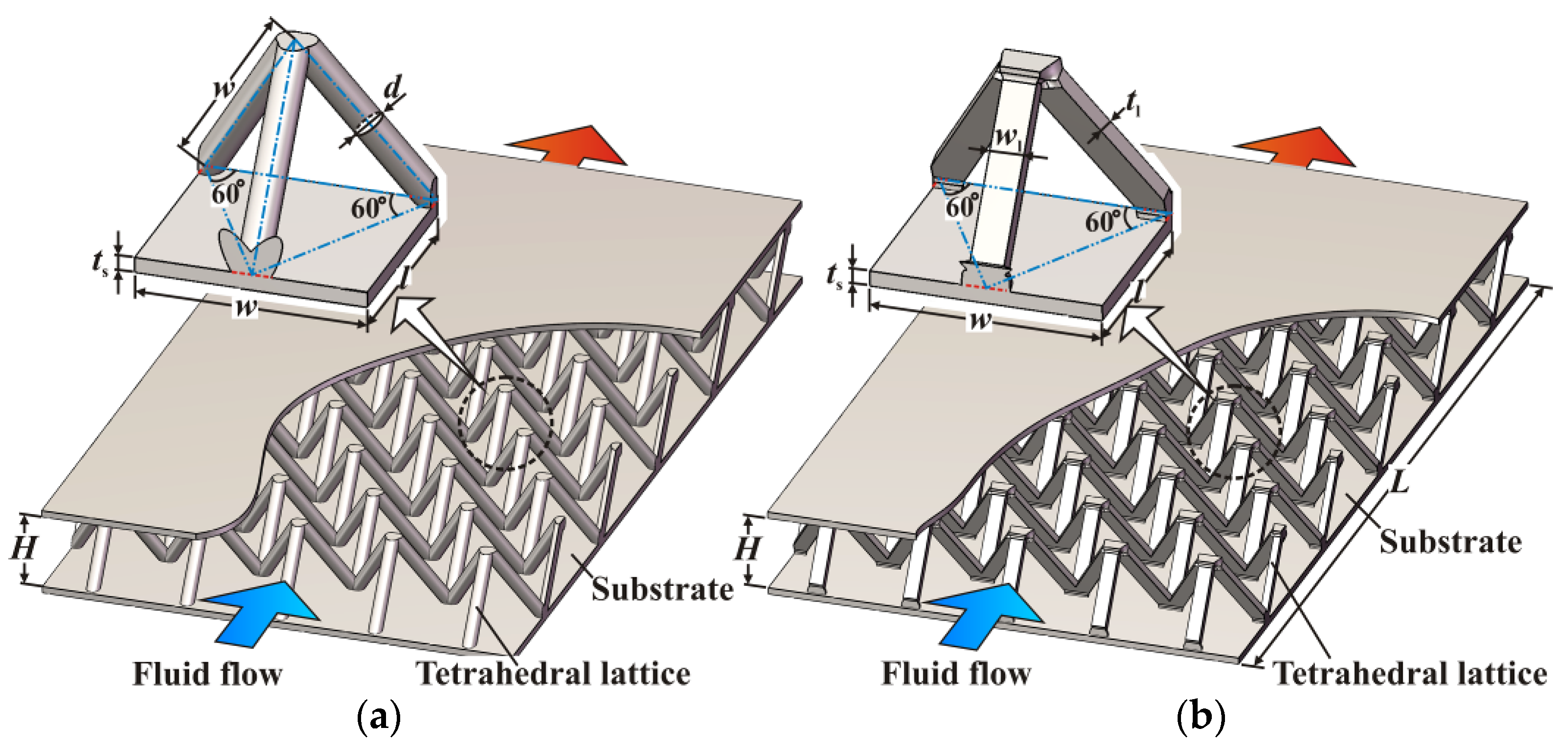
The tetrahedral lattice cored sandwich panels numerically compared in the present study are schematically illustrated in Figure 2. The sandwich panel as shown in Figure 2a is generally fabricated by investment casting, while the other one in Figure 2b can be obtained by brazing two substrates, with the lattice core fabricated by the metal sheet folding method. Details of the fabrication procedures can be found in [10,16], respectively. Hereafter, they are separately denoted as ‘casted sandwich panel’ and ‘brazed sandwich panel’ for convenience.
The unit cells of both sandwich panels have identical overall dimensions, i.e., l = 12.7 mm, w = 14.7 mm and H = 11.6 mm, corresponding to an identical core porosity of 0.953. Herein, the core porosity, respectively denoted as εC and εB for the casted sandwich panel and the brazed sandwich panel, is the ratio of the void volume to the total volume of a lattice unit cell. Along the flow direction, both sandwich panels incorporate ten tetrahedral unit cells, corresponding to an overall length (L) of 127 mm. The thickness (ts) of all the substrates is 1.0 mm. The ligaments of the casted lattice core have a circular cross-section with a diameter (d) of 1.8 mm; the surface area density of this lattice core (excluding surface of substrates) is calculated to be 98.1 m2/m3. For the brazed sandwich panel in particular, the ligaments have an identical square cross-section (wl = 2.16 mm and tl = 1.13 mm); the surface area density of this lattice core is 113.7 m2/m3. In the present paper, the aforementioned surface area density refers to the ratio of total surface area of the ligaments to the total volume of a lattice unit cell. The morphological details of the sandwich panels are summarized in Table 1.
3. Details of Numerical Simulation
3.1. Computational Domain, Governing Equations and Boundary Conditions
In light of the geometrical symmetry of the sandwich panels, only ten half-unit cells and the corresponding fluid around them are considered, as detailed in Figure 3. To improve the numerical stability, two empty channels with a lengths of l and 3l, respectively, are configured upstream and downstream of the sandwich panel. It should be mentioned that the lattice core fabricated by the metal sheet folding method is modeled by using Sheet Metal Tools in Solidworks™, which can well represent the in-situ morphology.
The flow and heat transfer associated with the above sandwich panels are governed by the conservation of mass, momentum, and energy. To incorporate the turbulence effect, the shear stress transport (SST) turbulence model [27] with a dimensionless wall distance (y+) of less than 1.0 is adopted. The SST model has been proven to behave well for complex separated flow [28], which is expected in the present sandwich panels. In this paper, the basic assumptions include: (a) the flow and heat transfer are steady-state; (b) the fluid is incompressible; (c) both the solid and fluid have constant thermo-physical properties; (d) the body force term in the momentum equation is neglected; and (e) the viscous dissipation term in the energy equation of fluid is neglected. The corresponding governing equations in a tensor form, which have been well documented in [27,28,29], are summarized as follows:
- Continuity equation:
- Momentum equation:
- Energy equations:
- Turbulent kinetic energy equation:
- Turbulent frequency equation:
In the above equations, Vi (i = 1, 2, 3) denotes the three velocity components in the Cartesian coordinate system; xi (i = 1, 2, 3) refers to the Cartesian coordinate components; ρf is the density of the fluid; p is the static pressure; μf is the dynamic viscosity of the fluid; μt is the turbulent viscosity; Tf denotes the fluid temperature; kf is the thermal conductivity of the fluid; cpf is the specific heat of the fluid; Prt is the turbulent Prandtl number; Ts is the solid temperature; k is the turbulent kinetic energy; Pk refers to the production rate of turbulent kinetic energy due to fluid viscosity; ω is the turbulent frequency; F1 is a non-dimensional blending function; and the other symbols are the model constants.
In Equations (2) to (5), the turbulent viscosity (μt) and turbulence production rate (Pk) are separately defined as:
In Equations (6) and (7), the strain rate S′ and the dimensionless function F2 are separately defined as:
In Equation (9), y′ denotes the minimum distance from an arbitrary point to its surrounding solid walls. The blending function F1 is defined as:
In Equation (10), the term CDkω is defined as:
In Equations (4) and (5), the coefficients α3, β3, σk3, and σω3 are separately calculated as follows:
The model constants in the above equations are summarized in Table 2.
For a given mass flow rate of the working fluid (i.e., air in the present study), fully developed isothermal flow between two parallel plates is first simulated; for brevity, the details of this simple model are not shown here. Then the obtained flow field in conjunction with a constant static temperature (Tin) of 298.15 K is specified at the inlet of the computational domain as the inlet boundary condition. The mass flow rate is specified at the outlet to ensure mass conservation. The side surfaces of both the fluid and solid domains are set to be symmetric. A constant heat flux (q″) of 8000 W/m2 is applied to the outer surface of the bottom substrate, while the other walls are set to be adiabatic. For the interface between the solid and fluid domains, conservative interface flux and no-slip conditions are adopted.
The details of the numerical simulations are summarized in Table 3. For comparison between the two different sandwich panels, the height of the lattice core (H) is selected as the characteristic length scale; correspondingly, the Reynolds number in Table 3 is defined as:
where Um is the mean velocity along the channel height at the inlet of the computational domain. According to [20], the flow considered in the present study is fully turbulent.
3.2. Numerical Methods
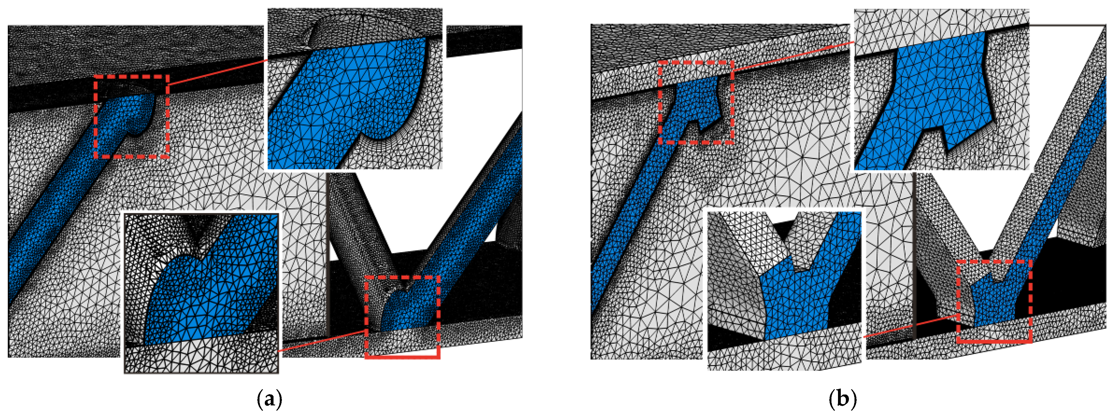
Due to the geometrical complexity of the present metallic lattices, an unstructured mesh composed of tetrahedral and prism elements is adopted to discretize both the solid and fluid domains as shown in Figure 4. Fine meshes incorporating nine layers of prism elements are generated near all no-slip walls to well resolve the flow and thermal boundary layers; the height of the first layer of elements away from the solid walls is set to be 0.01 mm. To save computational cost, relatively coarse mesh is adopted for regions away from the walls. A smooth transition of the mesh is ensured to minimize numerical error.
The conjugate flow and heat transfer problem is solved in the commercial software package ANSYS CFX 15.0 (ANSYS Inc., Canonsburg, PA, USA) based on the finite volume method and time-marching algorithm. The fluid is assumed to be incompressible and has constant thermo-physical properties as given in Table 3. A high resolution scheme and a central difference scheme are selected to discretize the advection terms and the diffusion terms in the governing equations, respectively. The solution is thought to be converged when the normalized residuals of all the governing equations are less than 10−5. Correspondingly, the average temperature on the heated solid wall and the friction factor almost remain unchanged, with a variation less than 0.1%.
3.3. Mesh Independency
For the mesh sensitivity evaluation, two dimensionless parameters are defined. First, the overall Nusselt number (Nuoverall) as an index of heat transfer is defined as:
The overall heat transfer coefficient (hoverall) for each unit cell is defined as:
where Twm is the inner surface temperature at the center of the substrate corresponding to each unit cell and Tfb is the local bulk mean fluid temperature, which can be calculated based on the energy balance as:
where yL is the distance between the inlet and the target point along the flow direction.
Second, the friction factor (f) as an evaluation index of the pressure drop is defined as:
where Δp is the pressure drop through the sandwich panel and L is the length of the sandwich panel along the flow direction as previously shown in Figure 2.
For the casted sandwich panel, the mesh sensitivity is examined at the highest Reynolds number (i.e., 5700) within the range of 3209–5700 considered in the present study. Three sets of meshes with 7,649,638, 13,666,657, and 18,690,337 elements are separately generated. As revealed by Table 4, the corresponding overall Nusselt number and the friction factor from the last two meshes show a discrepancy less than 1%, which is acceptable. Therefore, the mesh with 13,666,657 elements is used for all subsequent simulations. For the brazed sandwich panel, based on our previous experience during simulating a more complex X-type lattice cored sandwich panel [18], the mesh with 21,4450,432 elements is sufficient to obtain a mesh-independent solution.
4. Discussion of Results
4.1. Validation of the Numerical Model
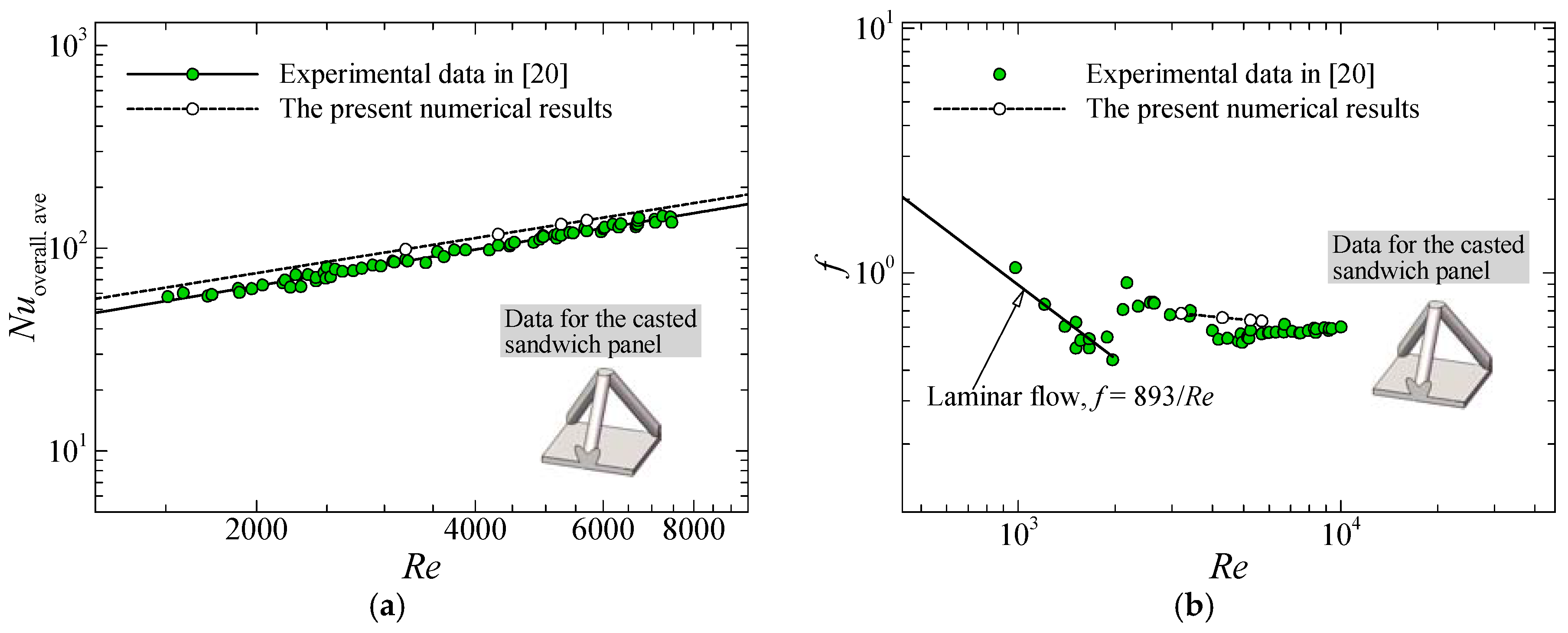
Before a reliable comparison between the sandwich panels, validation of the present numerical model is carried out. To this end, convective heat transfer in a sandwich panel cored with a casted tetrahedral lattice is first simulated according to the experimental configuration and conditions provided in [20]. The casted tetrahedral lattice tested by Kim et al. [20] has the same topology and material thermal conductivity with the one investigated in the present study, as shown in Figure 2a. Both sandwich panels incorporate ten unit cells along the flow direction. The thermo-fluidic boundary conditions for the inlet and all the solid walls in the present numerical simulation are identical to those adopted in the experiments in [20]. Figure 5a first presents a comparison of the average overall Nusselt number between the present numerical results and the experimental data in [20]. It should be noted that the average overall heat transfer coefficient in the Nusselt number is based on the applied heat flux on the substrate, the average substrate temperature along the flow direction, and the inlet air temperature as detailed in [20]. It can be seen that the Nusselt numbers obtained numerically and experimentally agree reasonably well with each other, exhibiting a deviation of 12–13% within the simulated Reynolds number range of 3210 to 5700. Figure 5b further shows a comparison of friction factors obtained experimentally and numerically within the turbulent regime. The present numerical results are also in reasonable agreement with the experimental data. In consideration of the measurement uncertainties of 8.3% and 9.7% for the Nusselt number and friction factor, respectively, in [20], the discrepancy exhibited by Figure 5 is acceptable. Given that an identical setup is adopted for both sandwich panels compared below, the numerical model is believed to be suitable for clarifying the relative merits between the sandwich panels.
4.2. Comparison of Overall Heat Transfer Characteristics
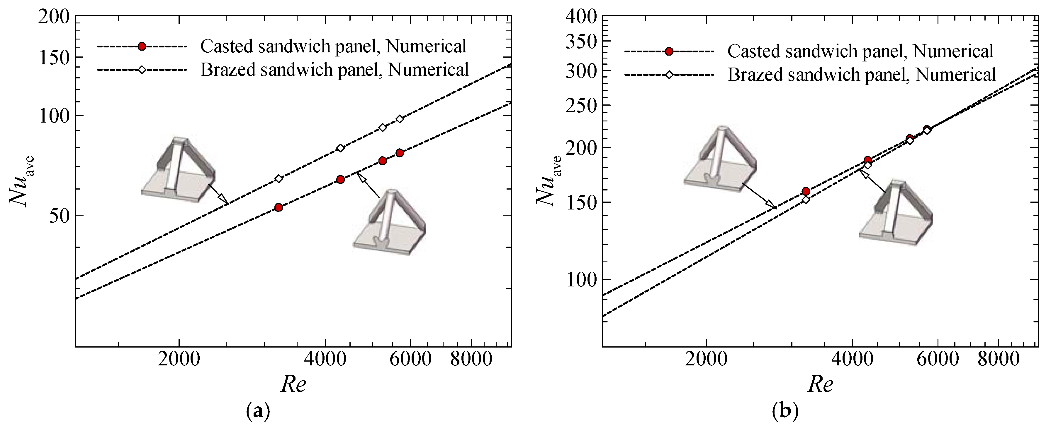
As multifunctional engineering structures, the overall heat transfer performance of the sandwich panels is the primary focus and is therefore considered first. Figure 6a presents the streamwise profiles of the overall Nusselt number as defined by Equations (14) to (16). For both sandwich panels, the overall Nusselt number increases evidently along the flow direction within the first four unit cells, which is attributed to the entry effect. Once the fully developed flow between the parallel plates enters the sandwich panel, it is redistributed by the lattice core. Such flow mixing gradually intensifies along the flow direction, leading to gradual enhancement of convective heat transfer. Within the fifth to the eighth unit cells, the Nusselt number approximately remains constant, where the flow is approximately fully developed. Then an evident increase of the Nusselt number is observable within the last two unit cells due to the exit effect. Within the ten unit cells, the overall Nusselt number for the brazed sandwich panel is 15–17% higher than that of the casted sandwich panel.
Subsequently, the averaged value of the overall Nusselt numbers for the ten unit cells, like those shown in Figure 6a, are calculated and plotted in Figure 6b as a function of the Reynolds number. It can be seen that the cheaper brazed sandwich panel thermally outperforms the casted sandwich panel under fixed Reynolds number conditions, although these two sandwich panels have identical porosity. Within the considered Reynolds number range of 3210 to 5700, the brazed sandwich panel provides a 13% to 16% higher averaged overall Nusselt number.
4.3. Comparison of Thermo-Fluidic Mechanisms
In view of the heat transfer enhancement by replacing the circular cross-sectioned ligaments with the rectangular cross-sectioned ones, it is of interest to understand the underlying heat transfer enhancement mechanisms. To this end, the detailed fluid flow and its effect on local heat transfer on various surfaces are compared between the sandwich panels. Such physical insights are believed to be beneficial for engineers to develop more effective PCMs.
As the basis of local heat transfer patterns, Figure 7 first presents an overview of the flow field as indicated by three-dimensional streamlines. It is clear that the sandwich panels have a similar flow pattern due to their similar topologies. Before each vertex, the boundary layer flow rolls up and forms a horseshoe vortex, which exerts strong shear to the endwall and the upstream surface of each vertex. In front of each ligament, the fluid is forced to flow upward due to the pressure gradient induced by the inclination of the ligament. Downstream of each ligament, large flow separation occurs; thus a pair of counter-rotating vortices presents. It should be noted that the width of the square ligament is higher than the diameter of the circular ligament. Therefore, the brazed sandwich panel has bigger vertexes and results in more evident blockage of the flow by the ligaments. The bigger vertexes and wider ligaments can intensify the horseshoe and contour-rotating vortices. Further, the flow velocity in the mainstream of the brazed sandwich panel is evidently higher than that of the casted sandwich panel as a result of a higher blockage ratio.
Corresponding to the above primary and secondary flows, Figure 8 presents the distribution of turbulent kinetic energy (Et) on an x-y plane placed 0.1 mm away from the heated endwall. For both sandwich panels, the strong horseshoe vortex and the counter-rotating vortex pair lead to strong turbulent flow mixing upstream and downstream of each vertex as indicated by the large turbulent kinetic energy value. It can be clearly seen that the bigger square vertex intensified flow mixing around and downstream of each vertex as compared to the casted sandwich panel.
Subsequently, local heat transfer characteristics are discussed based on the above flow characterization. Figure 9 presents the endwall heat transfer pattern as indicated by the local Nusselt number, which is based on local heat flux, wall temperature, and bulk mean fluid temperature. An arc-shaped high heat transfer region is clearly visible around each vertex as a result of the strong shear by the horseshoe vortex. Downstream of each vertex, the interaction between the counter-rotating vortices and the mainstream leads to stronger flow mixing as indicated by the turbulent kinetic energy distribution in Figure 8. As a result, local heat transfer is enhanced. It can therefore be concluded that the unique morphology of the square ligaments leads to a more prominent flow mixing, which leads to an evidently higher endwall heat transfer.
Figure 10 presents local heat transfer patterns on the ligaments. On the upstream surface, local heat transfer is dominated by the high velocity mainstream flow. For each sandwich panel, two types of ligaments with different heat transfer patterns are observable. On the downstream surface, local heat transfer is dominated by the low-momentum secondary flow, i.e., the counter-rotating vortex pair. Overall, both sandwich panels show a similar heat transfer pattern.
Figure 11 finally shows a comparison of the area-average Nusselt number (Nuave) on the endwall and ligaments as a quantitative evaluation. Within the simulated Reynolds number range, the brazed sandwich panel provides a 22–27% higher Nusselt number on the endwall as indicated by Figure 11a. Similar heat transfer performance on the ligaments is revealed by Figure 11b. It is now clear that enhanced heat transfer on the endwall and the higher surface area density of the brazed sandwich panel are the dominant mechanisms for enhanced heat transfer at a fixed Reynolds number.
4.4. Comparison of Pressure Drop Characteristics
For a heat transfer medium such as the present metallic lattice core, a pressure drop is the second evaluation index related to pumping power that is discussed in this section. Figure 12a first presents the streamwise variation of static pressure at a representative line on inner surface of the top substrate (x = 0 and z = H). In this figure, the pressure coefficient Cp is defined as:
It can be seen that the pressure distribution in the first unit cell is somewhat different from that in other unit cells due to the entry effect. Within other unit cells, the pattern of pressure drop distribution repeats, corresponding to an approximately identical pressure drop through each unit cell. The exit effect is not clearly observable.
Figure 12b presents the friction factor as defined in Equation (17) at various Reynolds numbers. For both sandwich panels, the friction factor slightly decreases with the increase of Reynolds number. Within the Reynolds number range of 3210 to 5700, the brazed sandwich panel provides a 1.6 to 1.7 times higher friction factor. More evident flow separation induced by the sharp edges of the ligaments and a more evident blockage effect are responsible for the higher pressure drop of the brazed sandwich panel at a given Reynolds number.
4.5. Comparison of Overall Thermal Performance
It has been demonstrated by Figure 6 and Figure 12 that, for a given Reynolds number, the brazed sandwich panel provides a higher Nusselt number but exhibits a higher friction factor as well. It is therefore beneficial to compare their thermal performance at fixed pumping power conditions. According to the argument in [31], the pumping power can be evaluated by a non-dimensional parameter fRe3, which is adopted in the present study. Figure 13 presents the variation of the average overall Nusselt number at various dimensionless pumping powers. Within the Reynolds number range considered in the present study, the casted and brazed sandwich panels approximately have identical thermal performances. Given that the brazed sandwich panel is more cost-effective and easier to make, the brazed sandwich panel may be superior from an engineering application point of view.
5. Conclusions
Focusing on multifunctional applications in which the heat transfer elements are required to sustain mechanical and thermal loads concurrently, this paper presents a thermo-fluidic comparison between the convectional casted tetrahedral lattice cored sandwich panel and a more cost-effective sandwich panel cored with a tetrahedral lattice fabricated by the metal sheet folding method. Both lattice cores have identical porosity. After the validation of the numerical model, the overall and local fluid flow and heat transfer characteristics are explored. The conclusions drawn in this study are summarized as follows.
(1) For a given Reynolds number and porosity, the brazed sandwich panel exhibits a 13% to 16% higher averaged overall Nusselt number relative to the cased sandwich panel. Therefore, the former may be superior when a coolant mass flow rate is given.
(2) For a given porosity, the bigger vertex and higher blockage ratio of the brazed sandwich panel intensify the horseshoe vortex around each vertex and the counter-rotating vortex pair downstream of each ligament. Thus stronger turbulent flow mixing occurs near the endwall, which enhances endwall heat transfer by 22% to 27%. Both sandwich panels exhibit similar heat transfer on the ligaments. Enhanced endwall heat transfer and higher surface area density are the mechanisms underlying the superior overall heat transfer of the brazed sandwich relative to the casted one.
(3) For a given Reynolds number and porosity, the friction factor of the brazed sandwich panel is 1.5 to 1.7 times higher than that of the casted one. More evident flow separation as a result of the sharp edges of the rectangular ligaments and a higher blockage ratio is responsible for the pressure drop increment.
(4) For a given pumping power and porosity, the brazed sandwich panel has a similar heat transfer performance to the casted sandwich panel. Given that the brazed sandwich panel is more cost-effective and easier to make, it may be superior to the casted sandwich panel from an engineering application point of view.
Acknowledgments
This research was supported by the Fundamental Research Funds for the Central Universities (Grant No. 3102016QD058) in China and the Collaborative Project Between China Aerodynamics Research and Development Centre and the Northwestern Polytechnical University (Grant No. N2016MC0077).
Author Contributions
Xiaoqing Zhang and Xin Jin did all the numerical simulations. Xiaoqing Zhang, Xin Jin, Gongnan Xie, and Hongbin Yan analyzed the numerical results. Gongnan Xie and Hongbin Yan supervised this work. All of the authors have provided substantial contributions to the manuscript preparation.
Conflicts of Interest
The authors declare no conflict of interest.
Nomenclature
| a1 | model constant in Equation (6) |
| CDkω | a term defined in Equation (11) |
| Cp | static pressure coefficient |
| cpf | specific heat capacity of fluid (J/(kgK)) |
| d | diameter of the circular ligaments (m) |
| Et | turbulent kinetic energy (J) |
| F1 | non-dimensional blending function defined in Equation (10) |
| F2 | non-dimensional blending function defined in Equation (9) |
| f | friction factor |
| H | height of the lattice core (m) |
| hoverall | overall heat transfer coefficient (W/(m2K)) |
| k | specific turbulent kinetic energy (J/kg) |
| kf | thermal conductivity of fluid (W/(mK)) |
| ks | thermal conductivity of solid (W/(mK)) |
| L | length of the sandwich panel along the flow direction (m) |
| l | length of the unit cell along the flow direction (m) |
| Nu | local Nusselt number |
| Nuave | area-averaged value of local Nusselt number |
| Nuoverall | overall Nusselt number |
| Nuoverall, ave | average overall Nusselt number |
| Pk | production rate of turbulent kinetic energy due to fluid viscosity (J/(m3∙s)) |
| Prt | turbulent Prandtl number |
| p | static pressure (Pa) |
| q’ | heat flux (W/m2) |
| Re | Reynolds number |
| S′ | strain rate defined in Equation (8) (1/s) |
| Tfb | bulk mean fluid temperature corresponding to the central point of each unit cell (K) |
| Tin | inlet fluid temperature (K) |
| Tf | fluid temperature (K) |
| Ts | solid temperature (K) |
| tl | thickness of the rectangular cross-sectioned ligaments (m) |
| ts | thickness of the substrates of the sandwich panel (m) |
| Twm | local substrate temperature corresponding to the central point of each unit cell (K) |
| Um | mean velocity overall channel height at the inlet of the computational domain (m/s) |
| Vi (i =1, 2, 3) | velocity components in Cartesian coordinate system (m/s) |
| Vm | velocity magnitude (m/s) |
| w | width of the unit cell (m) |
| wl | width of the rectangular cross-sectioned ligaments (m) |
| xi | (i = 1, 2, 3) three components of Cartesian coordinate system (m) |
| x, y, z | Cartesian coordinate components (m) |
| yL | distance from the central point of each unit cell to the inlet (m) |
| y+ | dimensionless wall distance |
| y′ | minimum distance between a point to its surrounding solid wall in Equation (9) (m) |
Greek Symbols
| α1–α3 | model constants in Equation (12) |
| β1–β3 | model constants in Equation (12) |
| β′ | model constants in Equation (4) |
| Δp | pressure drop (Pa) |
| σk1–σk3 | model constants in Equation (12) |
| σω1–σω3 | model constants in Equation (12) |
| εB | core porosity of the brazed sandwich panel |
| εC | core porosity of the casted sandwich panel |
| μf | dynamic viscosity of fluid (Pa∙s) |
| μt | turbulent viscosity (Pa∙s) |
| ρf | density of fluid (kg/m3) |
| ρSA, B | core surface area density of the brazed sandwich panel (m2/m3) |
| ρSA, C | core surface area density of the casted sandwich panel (m2/m3) |
| ω | turbulent frequency (1/s) |
References
- Li, H.Y.; Wu, Y.X. Heat transfer characteristics of pin-fin heat sinks cooled by dual piezoelectric fans. Int. J. Therm. Sci. 2016, 110, 26–35. [Google Scholar] [CrossRef]
- Kim, T.H.; Do, K.H.; Kim, S.J. Closed-form correlations of pressure drop and thermal resistance for a plate fin heat sink with uniform air jet impingement. Energy Convers. Manag. 2017, 136, 340–349. [Google Scholar] [CrossRef]
- Ferrari, L.; Barbato, M.; Esser, B.; Petkov, I.; Kuhn, M.; Gianella, S.; Barcena, J.; Jimenez, C.; Francesconi, D.; Liedtke, V.; et al. Sandwich structured ceramic matrix composites with periodic cellular ceramic cores: An active cooled thermal protection for space vehicles. Compos. Struct. 2016, 154, 61–68. [Google Scholar] [CrossRef]
- Song, J.W.; Sun, B. Coupled numerical simulation of combustion and regenerative cooling in LOX/Methane rocket engines. Appl. Therm. Eng. 2016, 106, 762–773. [Google Scholar] [CrossRef]
- Feng, S.S.; Li, M.Z.; Joo, J.H.; Kang, K.J.; Kim, T.; Lu, T.J. Thermomechanical properties of brazed wire-woven bulk Kagome cellular metals for multifunctional applications. J. Therm. Heat Transf. 2012, 26, 66–74. [Google Scholar] [CrossRef]
- Yan, H.B.; Zhang, Q.C.; Lu, T.J. An X-type lattice cored ventilated brake disc with enhanced cooling performance. Int. J. Heat Mass Transf. 2015, 80, 458–468. [Google Scholar] [CrossRef]
- Yan, H.B.; Mew, T.; Lee, M.G.; Kang, K.J.; Lu, T.J.; kienhöfer, F.W.; Kim, T. Thermofluidic characteristics of a porous ventilated brake disk. ASME J. Heat Transf. 2015, 137, 022601. [Google Scholar] [CrossRef]
- Maloney, K.J.; Fink, K.D.; Schaedler, T.A.; Kolodziejska, J.A.; Jacobsen, A.J.; Roper, C.S. Multifunctional heat exchangers derived from three-dimensional micro-lattice structures. Int. J. Heat Mass Transf. 2012, 55, 2486–2493. [Google Scholar] [CrossRef]
- Wadley, H.N.G. Multifunctional periodic cellular metals. Philos. Trans. R. Soc. A 2006, 364, 31–68. [Google Scholar] [CrossRef] [PubMed]
- Wadley, H.N.G.; Fleck, N.A.; Evans, A.G. Fabrication and structural performance of periodic cellular metal sandwich structures. Compos. Sci. Technol. 2003, 63, 2331–2343. [Google Scholar] [CrossRef]
- Wei, K.; He, R.J.; Cheng, X.M.; Pei, Y.M.; Zhang, R.B.; Fang, D.N. Fabrication and heat transfer characteristics of C/SiC pyramidal core lattice sandwich panel. Appl. Therm. Eng. 2015, 81, 10–17. [Google Scholar] [CrossRef]
- Hoffmann, F. Heat Transfer Performance and Pressure Drop of Kagome Core Metal Truss Panels. Master’s Thesis, University of Cambridge, Cambridge, UK, 2002. [Google Scholar]
- Tian, J.; Lu, T.J.; Hodson, H.P.; Queheillalt, D.T.; Wadley, H.N.G. Cross flow heat exchange of textile cellular metal core sandwich panels. Int. J. Heat Mass Transf. 2007, 50, 2521–2536. [Google Scholar] [CrossRef]
- Kang, K.J. Wire-woven cellular metals: The present and future. Prog. Mater. Sci. 2015, 69, 213–307. [Google Scholar] [CrossRef]
- Pingle, S.M.; Fleck, N.A.; Deshpande, V.S.; Wadley, H.N.G. Collapse mechanism maps for the hollow pyramidal core of a sandwich panel under transverse shear. Int. J. Solids Struct. 2011, 48, 3417–3430. [Google Scholar] [CrossRef]
- Deshpande, V.S.; Fleck, N.A.; Ashby, M.F. Effective properties of the octet-truss lattice material. J. Mech. Phys. Solids 2001, 49, 1747–1769. [Google Scholar] [CrossRef]
- Zhang, Q.C.; Han, Y.J.; Chen, C.Q.; Lu, T.J. Ultralight X-type lattice sandwich structure (I): Concept, fabrication and experimental characterization. Sci. China Ser. E Technol. Sci. 2009, 52, 2147–2154. [Google Scholar] [CrossRef]
- Yan, H.B.; Zhang, Q.C.; Lu, T.J.; Kim, T. A lightweight X-type metallic lattice in single-phase forced convection. Int. J. Heat Mass Transf. 2015, 83, 273–283. [Google Scholar] [CrossRef]
- Kim, T.; Hodson, H.P.; Lu, T.J. Contribution of vortex structures and flow separation to local and overall pressure and heat transfer characteristics in an ultralightweight lattice material. Int. J. Heat Mass Transf. 2005, 48, 4243–4264. [Google Scholar] [CrossRef]
- Kim, T.; Zhao, C.Y.; Lu, T.J.; Hodson, H.P. Convective heat dissipation with lattice-frame materials. Mech. Mater. 2004, 36, 767–780. [Google Scholar] [CrossRef]
- Kim, T.; Hodson, H.P.; Lu, T.J. Fluid-flow and endwall heat-transfer characteristics of an ultralight lattice-frame material. Int. J. Heat Mass Transf. 2004, 47, 1129–1140. [Google Scholar] [CrossRef]
- Kim, T.; Hodson, H.P.; Lu, T.J. Pressure loss and heat transfer mechanisms in a lattice-frame structured heat exchanger. IMechE J. Mech. Eng. Sci. 2004, 218, 1321–1336. [Google Scholar] [CrossRef]
- Gao, L.; Sun, Y.G. Thermal control of composite sandwich structure with lattice truss cores. J. Therm. Heat Transf. 2015, 29, 47–54. [Google Scholar] [CrossRef]
- Gao, L.; Sun, Y.G. Fluid flow and heat transfer characteristics of composite lattice core sandwich structures. J. Therm. Heat Transf. 2014, 28, 258–269. [Google Scholar] [CrossRef]
- Joo, J.H.; Kang, K.J.; Kim, T.; Lu, T.J. Forced convective heat transfer in all metallic wire-woven bulk Kagome sandwich panels. Int. J. Heat Mass Transf. 2011, 54, 5658–5662. [Google Scholar] [CrossRef]
- Zhao, L.Y.; Ryan, S.M.; Ortega, J.K.; Ha, S.; Sharp, K.W.; Guest, J.K.; Hemker, K.J.; Weihs, T.P. Experimental investigation of 3D woven Cu lattices for heat exchanger applications. Int. J. Heat Mass Transf. 2016, 96, 296–311. [Google Scholar] [CrossRef]
- Menter, F.R. Two-equation eddy-viscosity turbulence models for engineering applications. AIAA J. 1994, 32, 1598–1605. [Google Scholar] [CrossRef]
- Menter, F.R.; Kuntz, M.; Langtry, R. Ten years of industrial experience with the SST turbulence model. In Turbulence Heat and Mass Transfer; Hanjalić, K., Nagano, Y., Tummers, M., Eds.; Begell House Inc.: Danbury, PA, USA, 2003; Volume 4, pp. 625–632. [Google Scholar]
- CFX 14.0. ANSYS CFX Solver Theory Guide; ANSYS Inc.: Canonsburg, DC, USA, 2012. [Google Scholar]
- Kim, T. Fluid-Flow and Heat-Transfer in a Lattice-Frame Material. Ph.D. Dissertation, University of Cambridge, Cambridge, UK, 2004. [Google Scholar]
- Tian, J.; Kim, T.; Lu, T.J.; Honson, H.P.; Queheillalt, D.T.; Sypeck, D.J.; Wadley, H.N.G. The effects of topology upon fluid-flow and heat-transfer within cellular copper structures. Int. J. Heat Mass Transf. 2004, 47, 3171–3186. [Google Scholar] [CrossRef]
Figure 1.
Multifunctional sandwich panels with metallic lattice cores fabricated using different methods.
Figure 1.
Multifunctional sandwich panels with metallic lattice cores fabricated using different methods.

Figure 2.
Sandwich panels investigated in the present study: (a) fabricated by investment casting (Casted sandwich panel); (b) fabricated by brazing the folded lattice core with substrates (Brazed sandwich panel).
Figure 2.
Sandwich panels investigated in the present study: (a) fabricated by investment casting (Casted sandwich panel); (b) fabricated by brazing the folded lattice core with substrates (Brazed sandwich panel).

Figure 3.
Schematic illustration of computational domain and boundary conditions.

Figure 4.
Representative mesh: (a) the casted sandwich panel; (b) the brazed sandwich panel.

Figure 5.
Validation of the numerical model via a comparison between the present numerical results and the experimental data in [20] for the casted sandwich panel: (a) average overall Nusselt number; (b) friction factor.
Figure 5.
Validation of the numerical model via a comparison between the present numerical results and the experimental data in [20] for the casted sandwich panel: (a) average overall Nusselt number; (b) friction factor.

Figure 6.
Comparison of the overall Nusselt number at various Reynolds numbers between the casted and brazed sandwich panels: (a) streamwise profile of the Nusselt number at Re = 5700; (b) area-averaged overall Nusselt number.
Figure 6.
Comparison of the overall Nusselt number at various Reynolds numbers between the casted and brazed sandwich panels: (a) streamwise profile of the Nusselt number at Re = 5700; (b) area-averaged overall Nusselt number.

Figure 7.
Comparison of fluid flow behaviors as indicated by three-dimensional streamlines at Re = 5700: (a) the casted sandwich panel; (b) the brazed sandwich panel.
Figure 7.
Comparison of fluid flow behaviors as indicated by three-dimensional streamlines at Re = 5700: (a) the casted sandwich panel; (b) the brazed sandwich panel.

Figure 8.
Comparison of turbulent kinetic energy distribution on an x-y plane at z = 0.1 mm and at Re = 5700: (a) the casted sandwich panel; (b) the brazed sandwich panel.
Figure 8.
Comparison of turbulent kinetic energy distribution on an x-y plane at z = 0.1 mm and at Re = 5700: (a) the casted sandwich panel; (b) the brazed sandwich panel.

Figure 9.
Comparison of local heat transfer pattern on the heated endwall at Re = 5700: (a) the casted sandwich panel; (b) the brazed sandwich panel.
Figure 9.
Comparison of local heat transfer pattern on the heated endwall at Re = 5700: (a) the casted sandwich panel; (b) the brazed sandwich panel.

Figure 10.
Comparison of local heat transfer pattern on the lattice core at Re = 5700.

Figure 11.
Quantitative comparison of the area-averaged Nusselt number on (a) the heated endwall and (b) the surfaces of the ligaments at Re = 5700.
Figure 11.
Quantitative comparison of the area-averaged Nusselt number on (a) the heated endwall and (b) the surfaces of the ligaments at Re = 5700.

Figure 12.
Comparison of pressure drop at various Reynolds numbers between the sandwich panels: (a) profile of pressure coefficient along the streamwise direction at Re = 5700; (b) friction factor as a function of Reynolds number.
Figure 12.
Comparison of pressure drop at various Reynolds numbers between the sandwich panels: (a) profile of pressure coefficient along the streamwise direction at Re = 5700; (b) friction factor as a function of Reynolds number.

Figure 13.
Comparison of the area-averaged overall Nusselt number as a function of non-dimensional pumping power between the casted and brazed sandwich panels.
Figure 13.
Comparison of the area-averaged overall Nusselt number as a function of non-dimensional pumping power between the casted and brazed sandwich panels.


Table 1.
Geometrical parameters of the sandwich panels numerically compared in the present study.
| Parameter | Value | Parameter | Value | Parameter | Value |
|---|---|---|---|---|---|
| d | 1.80 mm | tl | 1.13 mm | εB | 0.953 |
| H | 11.6 mm | ts | 1.00 mm | εC | 0.953 |
| l | 12.7 mm | w | 14.7 mm | ρSA, B | 113.7 m2/m3 |
| L | 127 mm | wl | 2.16 mm | ρSA, C | 98.1 m2/m3 |
Table 2.
Constants in the governing equations of the shear stress transport (SST) turbulence model [27,28,29]. Reproduced with permission from ANSYS Inc., 2012.
| Parameter | Value | Parameter | Value | Parameter | Value |
|---|---|---|---|---|---|
| α1 | 0.556 | β1 | 0.075 | σk1 | 0.85 |
| α2 | 0.44 | β2 | 0.0828 | σk2 | 1.0 |
| σω1 | 0.5 | a1 | 0.31 | Prt | 0.9 |
| σω2 | 0.856 | β′ | 0.09 | - | - |
Table 3.
A summary of details of the present numerical simulations [30]. Reproduced with permission from Cambridge University Press, 2004.
Table 3.
A summary of details of the present numerical simulations [30]. Reproduced with permission from Cambridge University Press, 2004.
| Parameter | Value | Parameter | Value |
|---|---|---|---|
| Specific heat of air, cpf | 1006 J/(kgK) | Thermal conductivity of solid, ks | 150.84 W/(mK) |
| Thermal conductivity of air, kf | 0.0242 W/(mK) | Applied heat flux, q″ | 8000 W/m2 |
| Dynamic viscosity of air, μf | 1.79×10⁻⁵ Pa∙s | Inlet air temperature, Tin | 298.15 K |
| Density of air, ρf | 1.225 kg/m3 | Reynolds number, Re | 3209–5700 |
Table 4.
The predicted Nusselt number and the friction factor for the casted sandwich panel with three different meshes at ReH = 5700.
Table 4.
The predicted Nusselt number and the friction factor for the casted sandwich panel with three different meshes at ReH = 5700.
| Total Elements | Nuoverall | f |
|---|---|---|
| 7,649,638 | 134.2891 | 0.6217 |
| 13,666,657 | 137.4246 | 0.6363 |
| 18,690,337 | 137.6380 | 0.6401 |
© 2017 by the authors. Licensee MDPI, Basel, Switzerland. This article is an open access article distributed under the terms and conditions of the Creative Commons Attribution (CC BY) license (http://creativecommons.org/licenses/by/4.0/).
Share and Cite
MDPI and ACS Style
Zhang, X.; Jin, X.; Xie, G.; Yan, H. Thermo-Fluidic Comparison between Sandwich Panels with Tetrahedral Lattice Cores Fabricated by Casting and Metal Sheet Folding. Energies 2017, 10, 906. https://doi.org/10.3390/en10070906
AMA Style
Zhang X, Jin X, Xie G, Yan H. Thermo-Fluidic Comparison between Sandwich Panels with Tetrahedral Lattice Cores Fabricated by Casting and Metal Sheet Folding. Energies. 2017; 10(7):906. https://doi.org/10.3390/en10070906
Chicago/Turabian StyleZhang, Xiaoqing, Xin Jin, Gongnan Xie, and Hongbin Yan. 2017. "Thermo-Fluidic Comparison between Sandwich Panels with Tetrahedral Lattice Cores Fabricated by Casting and Metal Sheet Folding" Energies 10, no. 7: 906. https://doi.org/10.3390/en10070906
Note that from the first issue of 2016, this journal uses article numbers instead of page numbers. See further details here.