A Novel Modular-Stator Outer-Rotor Flux-Switching Permanent-Magnet Motor

1
School of Automation, Beijing Institute of Technology, Beijing 100081, China
2
Key Laboratory for Intelligent Control & Decision of Complex Systems, Beijing Institute of Technology, Beijing 100081, China
*
Author to whom correspondence should be addressed.
Energies 2017, 10(7), 937; https://doi.org/10.3390/en10070937
Submission received: 12 April 2017
/
Revised: 9 June 2017
/
Accepted: 2 July 2017
/
Published: 6 July 2017
(This article belongs to the Section I: Energy Fundamentals and Conversion)
Abstract
:A novel modular-stator outer-rotor flux-switching permanent-magnet (MSOR-FSPM) motor is proposed and studied in this paper. Structure, operation and design principles of the MSOR-FSPM motor are introduced and analyzed. Considering that the combination of different pole number and slot number has a great influence on the motor performance, the optimum rotor pole number for the 12-stator-slot MSOR-FSPM motor is researched to obtain good performance and make full use of the space in the MSOR-FSPM motor. The influences of rotor pole number on cogging torque, torque ripple and electromagnetic torque are analyzed and a 12-slot/10-pole MSOR-FSPM motor was chosen for further study. Then, several main parameters of the 12-slot/10-pole MSOR-FSPM motor were optimized to reduce the torque ripple. Finally, the utilization of permanent magnet (PM) in the MSOR-FSPM motor and a conventional outer-rotor flux-switching permanent-magnet (COR-FSPM) motor are compared and analyzed from the point of view of magnetic flux path, and verified by the finite element method (FEM). The FEM results show that the PM volume of MSOR-FSPM motor is only 54.04% of that in a COR-FSPM motor, but its average electromagnetic torque can reach more than 75% of the torque of COR-FSPM motor.
1. Introduction
Due to the serious air pollution and energy shortages all over the world, governments have put forward plans for energy conservation and emission reduction requirements for vehicles. Electric vehicles (EVs) with clean and low energy consumption are widely proposed to effectively alleviate this problem [1]. As the key component, the drive motor is expected to have high torque density, high power density, strong overload capacity, great fault tolerance capability, wide constant power speed range and low cost [2].
Different drive motors have been tried in EVs’ electromechanical energy conversion systems, such as permanent magnet synchronous motors (PMSMs), induction motors, DC motors, and brushless DC permanent magnet motors [3,4]. PMSMs are more favorable candidates in the EVs field due to their high power density, high efficiency and compact structure. Moreover, their structure can be changed conveniently according to different applications [5]. PMSMs can be divided into rotor PM motors and stator PM motors according to whether the PMs are placed on the rotor or the stator. In rotor PM motors, the maximum load is limited by the temperature rise of the PMs and the PMs have the risk of irreversible demagnetization. Stator PM motors, such as flux-reverse permanent-magnet (FRPM) motors, doubly-salient permanent-magnet (DSPM) motors and flux-switching permanent-magnet (FSPM) motors, have been widely investigated in recent years due to their simple and robust rotor structure [6,7,8]. Compared with rotor PM motors, the armature windings and PMs of stator PM motors are both placed on the stator, which could improve the cooling condition of PMs and prevent the PMs from sliding off due to the centrifugal force.
Compared with DSPM motors and FRPM motors, FSPM motors have more sinusoidal back electromotive force (EMF) which is appropriate for brushless AC drive systems [9]. They have better torque and power density performance under starting and climbing conditions [10]. In addition, like for FSPM motors, the magnetic field excited by PMs is in parallel with that excited by armature currents, which is suitable for a wide speed range [11]. Therefore, a large number of researchers have paid more attention to FSPM motors. In [12], the concept and working principles of a FSPM motor were first proposed, and its design principles were established based on the design theory of conventional PMSMs. In [13], a multi-tooth FSPM motor was proposed, whose stator tooth extends a number of virtual teeth; it is verified that this topology has lower torque ripple, and higher torque density at low load. In [14], a topology with step skewing rotor was researched and the finite element method (FEM) results showed that a rotor with reasonable skewing angle has a significant weakening effect on the cogging torque and torque ripple. In order to reduce the rotor core volume and motor losses, a novel FSPM motor with segmental rotor was researched in [15]; its rotor consists of a plurality of separate sector-shaped salient poles and the total motor losses can be reduced by 13% under the same output power. In order to make FSPM motor have larger torque at low speed and a wider constant power speed range, various hybrid excitation FSPM motors were proposed [16]. Moreover, the fault tolerance capability of FSPM motors is also a hot topic, as FSPM motors with fault tolerance capability can continue to work under fault conditions to improve the reliability of the EVs [17,18,19]. In general, because FSPM motors have simple structure, good controllability, high power density and fault-tolerant performance, they are a good selection for EV drive systems [20], but most of the researched FSPM motors have inner-rotor structures.
Nowadays, outer-rotor motors, which can be used as in-wheel motors in the EV industry, have become a key technology, because they can omit the clutch, the reduction gear and the differential gear to provide extra passenger space and independent direct control to make EVs more secure [21]. In addition, tire maintenance is convenient and low cost due to the simple rotor structure of FSPM motors. Therefore, outer-rotor FSPM motors, which combine the advantages of FSPM motors and outer-rotor motors, are generating more and more interest. In [22], an outer-rotor FSPM motor was first proposed and designed using FEM. The loss and efficiency of this motor were researched, and the flux-weakening capability analyzed and further improved by segmental PMs with iron bridges in [23]. Furthermore, its torque ripple was reduced by a systematic multi-level design and control scheme in [24]. In [25], an outer-rotor FSPM motor with specific wedge-shaped magnets that exhibits better torque capability than its counterparts was researched. Based on the principles of an inner-rotor FSPM motor with hybrid excitation, preliminary studies on the design parameters of outer-rotor FSPM motor with hybrid excitation were discussed and presented in [26]. In [27], a new outer-rotor V-shaped FSPM (V-FSPM) motor was proposed to improve the PM utilization and the output torque. In the V-FSPM motor, the stator pole number is reduced by half and two rectangular PM pieces are purposely placed in one stator pole in a V shape, which can realize flux focusing effects to increase the flux density in the air gap. Experimental tests of the above studies verify that outer-rotor FSPM motors are suitable for in-wheel traction.
To sum up, outer-rotor FSPM motors are viable for further research and have great potential to be used in EVs traction drives. However, the amount of PMs is excessive and the coupling between three phases is obvious in the outer-rotor FSPM topologies mentioned above. Therefore, this paper proposes a novel modular-stator outer-rotor flux-switching permanent-magnet (MSOR-FSPM) motor whose modular stator can be easily replaced. Compared with conventional outer-rotor flux-switching permanent-magnet (COR-FSPM) motors, the amount PM of the MSOR-FSPM motor is reduced and PM utilization is improved. In this paper, the structure, operation and design principles of the MSOR-FSPM motor are introduced and analyzed. Secondly, the rotor pole number for the 12-stator-slot MSOR-FSPM motor is researched, its influences on cogging torque, torque ripple and electromagnetic torque are analyzed and a suitable topology is chosen for further study. Thirdly, several main dimensions of the chosen MSOR-FSPM motor are optimized to reduce the torque ripple. Finally, the utilization of PMs in a MSOR-FSPM motor and a COR-FSPM motor is compared from the point of view of the magnetic flux path and verified by the FEM.
2. Structure and Operation Principle of the MSOR-FSPM Motor
2.1. Structure of the MSOR-FSPM Motor
A 3D structure and a cross-sectional view of the MSOR-FSPM motor are shown in Figure 1. The rotor consists of a simple laminated iron core with salient poles. The stator consists of three modules MA, MB, and MC. The structure, size and material of three modules are all the same. Each module represents one phase and consists of one “W”-shaped laminated segment, two “V”-shaped laminated segments and two PMs. “W”-shaped laminated segment is placed in the middle of the module, two “V”-shaped laminated segments are placed at the both ends of the module, and the two PMs are respectively sandwiched between the “V”-shaped laminated segment and “W”-shaped laminated segment. The magnetization direction of each PM is along circumference and it is opposite between the adjacent PMs. Furthermore, non-overlapping concentrated armature windings are placed in each stator slot and each phase windings are connected in series. In order to obtain balanced three-phase back-EMF and reduce the coupling between three phases, non-magnetic blocks are placed between the adjacent modules. After the windings are placed in the stator slot, the whole stator will be strengthened by epoxy resin to ensure the mechanical strength of modular stator.
2.2. Operation Principle of the MSOR-FSPM Motor
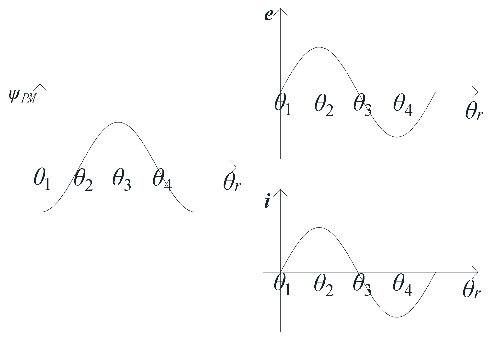
For simplicity, the module MA is taken as an example to explain how the electromagnetic torque is produced. When the rotor rotates to the different positions θ1, θ2, θ3 and θ4, the distributions of the main magnetic flux lines in module MA are shown in Figure 2. The rotor poles align with the stator teeth when the rotor is at position θ1, and all magnetic flux lines go through winding A from stator to rotor and the PM flux linkage of winding A reaches its negative extreme value. Then, the rotor pole aligns with one PM and the rotor slot aligns with the other PM when the rotor rotates to the position θ2, no magnetic flux lines go through winding A if flux leakage is neglected. Next, the rotor poles again align with the stator teeth when the rotor rotates to position θ3. However, the magnetic flux lines go through winding A from rotor to stator and its direction is opposite to that of position θ1, the PM flux linkage of winding A reaches the positive extreme value. Finally, the rotor pole aligns with one PM and rotor slot aligns with the other PM when the rotor rotates to the position θ4, and no magnetic flux lines go through winding A once again. If the rotor continues rotating, the same processes will be repeated periodically. It can be found from the ΨPM − θr curve in Figure 3 that the flux linkage of winding A is bipolar and it realizes “switching” flux at the position of θ2 and θ4. Analyzed from the “generator-oriented” perspective, back-EMF can be induced based on the Faraday’s law of electromagnetic induction. If appropriate current is fed into the windings, electromagnetic torque will be produced to drive the rotor rotating.
2.3. Basic Design Principles of the MSOR-FSPM Motor
Based on the traditional power equation of FSPM motors, the design equation of the MSOR-FSPM motor can be deduced as [28]:
where Dso is stator outer diameter, lef is the effective length of the motor, Pout is the output power, Nr is the number of rotor poles, Ns is the number of stator poles, kd is magnetic flux leakage coefficient, ks is chute coefficient, ksio is the ratio of inside diameter and outside diameter of the stator, As is the line load, Bgmax is the peak air gap flux density at no-load, n is the rotation speed, cs is the pole arc coefficient of stator tooth, and η is the motor efficiency.
The main design parameters of MSOR-FSPM motor are shown in Figure 1b. The air gap length lg is chosen as 0.5 mm. It is the same with inner-rotor FSPM motor that stator tooth width wst, stator yoke height hsy and permanent magnet width wpm are equal to each other, but the stator slot width ws is three times the stator tooth width wst to obtain a larger stator slot area. When the stator diameter Dso is obtained, wst, hsy, wpm and ws are calculated according the following relationship [22]:
In order to prevent the magnetic saturation of the rotor pole and rotor yoke, the rotor pole height hrt and rotor yoke height hry are preselected as 1.4 wst. Moreover, the rotor pole arc coefficient is pre-selected as 0.5. After the main parameters, such as the dimensions of the stator and the rotor pole, are calculated by using the relationships above, the rotor outer radius Rro can be obtained as:
This MSOR-FSPM motor is used for a four-wheel drive vehicle. Its output power Pout is pre-chosen as 1.5 kW, which is appropriately reduced to obtain a small prototype motor to verify the theoretical analysis. The effective length lef of the motor is chosen as 100 mm, which is close to the length of in-wheel motor that used in EVs. When the theoretical sizes are obtained based on the above relationships, they are adjusted slightly considering the processing technology. For example, the main parameters of the initial designed 12-slot/10-pole MSOR-FSPM motor are shown in Table 1.
Based on the operation principle of MSOR-FSPM motor, the period of back-EMF and magnetic field is one rotor pole pitch. Hence, one rotor pole pitch of the MSOR-FSPM motor is equal to 360° (electrical angle), which is expressed as mechanical angle meeting the following Equation (4), and the electrical period of the back-EMF can be determined by the following Equation (5) [29]:
where τp is the mechanical angle between two adjacent rotor poles and its unit is degree (°); Nr is the number of rotor poles; n is rotation speed of rotor and its unit is revolutions per minute (r/min); tEMF is electrical period and its unit is second (s). In order to obtain balanced three-phase back-EMF, some key parameters of the stator modules should be carefully designed using the following equations:
where the value of k and l is 0 or 1, the three stator modules respectively represent phase A, phase B and phase C in the counter-clockwise direction when l is equal to 0, and respectively represent phase A, phase B and phase C in the clockwise direction when l is equal to 1; i, j, and h are all non-negative integer, τc is the mechanical angle between two adjacent slot conductors that belong to the same coil, τm is the mechanical angle between two adjacent PMs in each module, τd is the mechanical angle between two adjacent modules.
The single-coil back-EMF is the vector sum of two adjacent slot conductors. Equation (6) can make the phase angle of back-EMF in two adjacent slot conductors that belong to the same coil approximately antiphase, which lets the coil pitch factor be approximately equal to 1. Equation (7) can make the phase angle of back-EMF in different coils that belong to the same phase winding be cophase or antiphase, which lets the distribution factor of the winding be close to 1. Equation (8) can make the phase difference of no-load back-EMF between different windings be 120° (electrical angle).
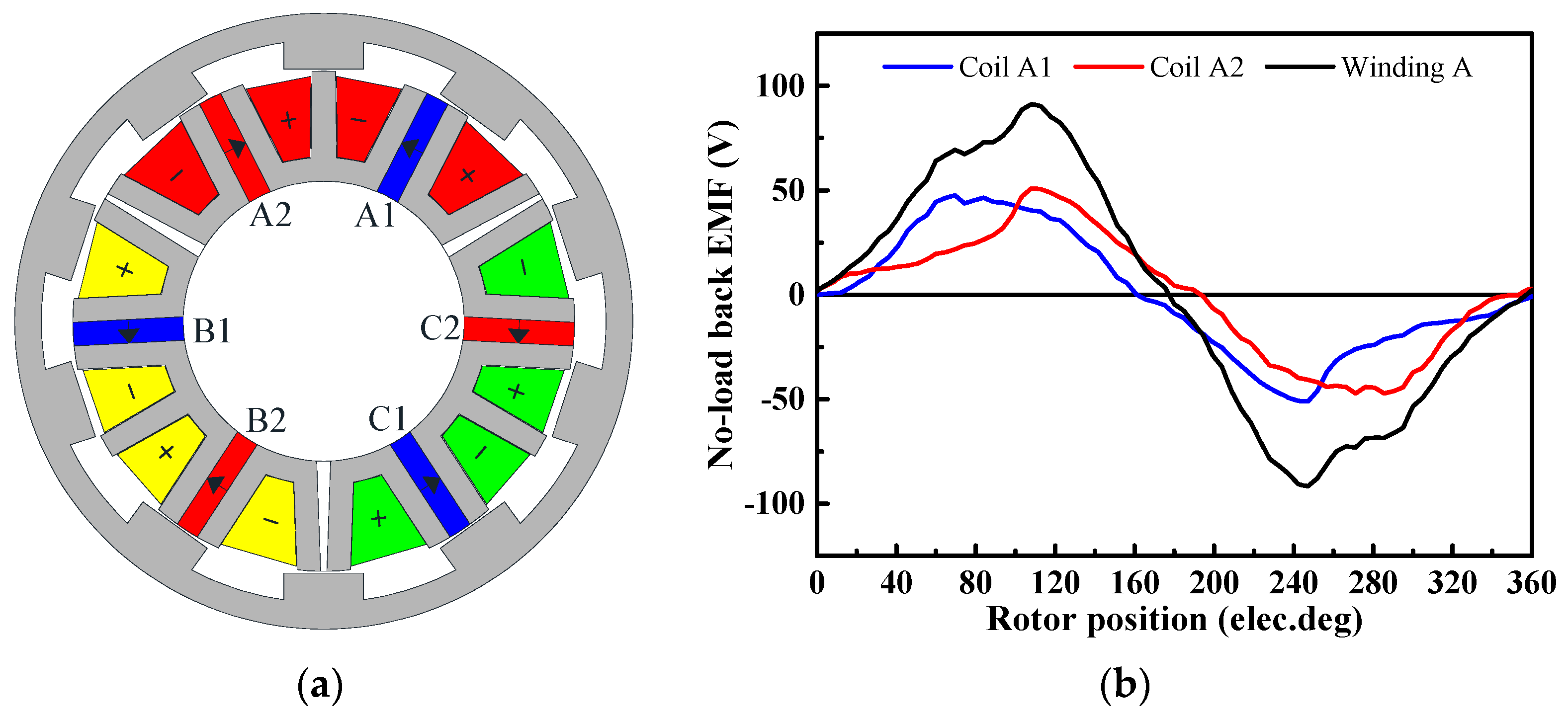
It is worth noting that the value of k has a significant effect on the no-load back-EMF waveforms. For example, a 12-slot/20-pole MSOR-FSPM motor is shown in Figure 4, in which the value of k is 1. The winding connection is shown as Figure 4a. It can be found from Figure 4b that the no-load back-EMF waveforms of coil A1 and coil A2 are almost the same, but the positive and negative back-EMF waveforms induced in coils are asymmetrical, which makes the no-load back-EMF waveforms of windings seriously asymmetrical. A 12-solt/10-pole MSOR-FSPM motor is shown in Figure 5, in which the value of k is 0. The winding connection is shown as Figure 5a. It can be found from Figure 5b that the no-load back-EMF waveforms of coil A1 and coil A2 are different. But the positive back-EMF waveform of coil A1 is symmetrical with the negative back-EMF waveform of coil A2, and the negative back-EMF waveform of coil A1 is symmetrical with the positive back-EMF waveform of coil A2, which makes the no-load back-EMF waveforms of windings symmetrical. In order to prevent the asymmetrical winding back-EMF causing poor motor performances, the value of k is chosen as 1.
3. Influences of Rotor Pole Number
The electromagnetic torque can be derived by differentiating the co-energy with respect to the mechanical angle, the co-energy Wc and electromagnetic torque Tem with constant current can be given as the following Equations [30]:
where i is the coil current; L is the coil inductance; R and Rm are the reluctances seen by the magnetomotive force source and the magnetic field, respectively; Ncoil is the number of turns per coil; Φm is the magnetic flux of the PM; θ is the rotor position; Trm is the reluctance torque generated by winding inductance variations with rotor position; Tcog is the cogging torque produced by the PM field energy variations with rotor position; TPM is the PM torque produced by the interaction of the magnetic field generated by PMs and the coil current.
However, the cogging torque Tcog will not produce an effective average torque but only cause torque ripple Trip. The torque ripple Trip can be defined by the maximum torque Tmax, the minimum torque Tmin and average torque Tavg given by the following Equation (11):
Therefore, cogging torque Tcog has great influences on electromagnetic torque Tem and torque ripple Trip. If the energy variation in the iron core is ignored, the co-energy Wc can be replaced by air gap energy, the cogging torque expression in FSPM motor can be obtained by [30]:
where Lstk is the axial stack length; r1 is the outer radius of the stator; r2 is the inner radius of the rotor; Gn and BrnNL are the corresponding Fourier coefficients of the relative air gap permeance function and flux density function; NL = Nr/(LCM(Ns, Nr)), and LCM(Ns, Nr) is the least common multiple of the number of stator poles and number of rotor poles.
Equation (12) shows that cogging torque can be weakened by choosing an appropriate number of rotor poles, which will further enhance the torque stability. Therefore, the number of rotor poles in MSOR-FSPM motor should be carefully designed and meet the following principles:
- The number of rotor poles cannot be too large to ensure appropriate mechanical strength of rotor poles.
- The number of rotor poles cannot be a multiple of 3 to obtain three-phase back-EMF.
- The outside diameter, air gap length, stack length, PM width, and stator tooth width of different topologies keep constant.
- Equations (6)–(8) must be satisfied.
- The stator tooth cannot be supersaturated.
- The stator slot area is utilized as fully as possible.
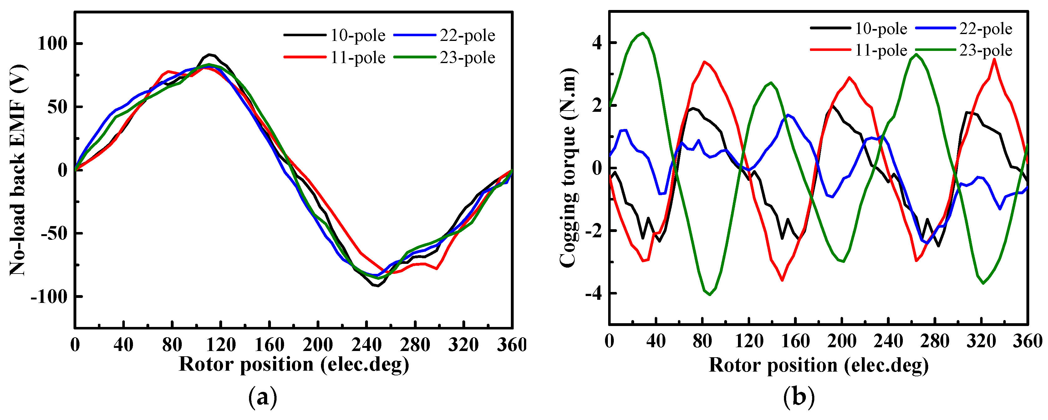
The appropriate numbers of rotor poles based on the above principles are 10, 11, 22, and 23. For these four motors, the mainly different parameters are shown in Table 2, and the no-load back-EMF waveforms of winding A and cogging torque waveforms are shown in Figure 6. It can be found from Figure 6a that the no-load back-EMF waveforms are almost coincident because different numbers of turns per coil are adopted to make the amplitude roughly equal to each other. It should be noted that the back-EMF waveforms of these four motors are seriously distorted. It can be found from Figure 2 that the positive magnetic flux path and the negative magnetic flux path of coils are not completely symmetrical, which results in distortion of coil back-EMF. Moreover, the magnetic flux paths of coil A1 and coil A2 are the same, the inherent harmonics of the coil back-EMF cannot be counteracted by each other when phase back-EMF is obtained. Therefore, the distortion of phase no-load back-EMF is serious. It can be seen from Figure 6b that cogging torque is the minimum and has the best periodicity when the rotor pole number is 10. Therefore, the 12-slot/10-pole MSOR-FSPM motor is chosen to be researched further in the next section.
4. Optimization of the Main Parameters in the 12-Slot/10-Pole MSOR-FSPM Motor
The average electromagnetic torque and torque ripple of the 12-slot/10-pole MSOR-FSPM motor are 19.97 N·m and 47.08%, respectively. It is obvious that the torque ripple is too large. The aim of this section is to reduce the torque ripple by optimizing the parameters that mainly influence the torque performance, and these parameters are shown in Figure 7. Considering the motor manufacture, it is not practical to place windings if the stator slot is fully open. In order to prevent windings slipping off the stator slot, it is appropriate to add a pole shoe to the stator slots to conveniently install the slot wedge. However, the pole shoe can change the magnetic field distributions, and the width of stator slot opening is an important factor to influence torque ripple and average torque. Therefore the shape and size of pole shoe (hw, hh, ht) should be strictly designed. On the other hand, rotor pole arc coefficient (wrp/τp) has a significant effect on the performances of the salient motor, rotor pole width (wrp) is changed to get an appropriate pole arc coefficient. In addition, it can be seen from Figure 6a that the distortion of no-load back-EMF is serious, which leads to torque harmonics when a sinusoidal current is fed into the windings. It is necessary to make the positive magnetic flux path symmetrical with the negative magnetic flux path to obtain low no-load back-EMF distortion. Therefore, the tooth width of the “V”-shaped laminated segments that adjoin with non-magnetic blocks should be reduced, and the reduced width (Vtw) is also optimized.
4.1. Stator Pole Shoe
There are two available pole shoe shapes—rectangle pole shoe and trapezoid pole shoe—which are shown in Figure 7. hh and hw are the height and width of the pole shoe, respectively. hh and hw are no larger than 2 mm to ensure the appropriate slot area. ht is the thickness of trapezoid pole shoe and it is equal to 2 mm. The combinations of different parameters and shapes of the pole shoe are expressed as “hw_hh rectangle” and “hw_hh trapezoid”. Cogging torque and electromagnetic torque of the main combinations are shown in Figure 8.
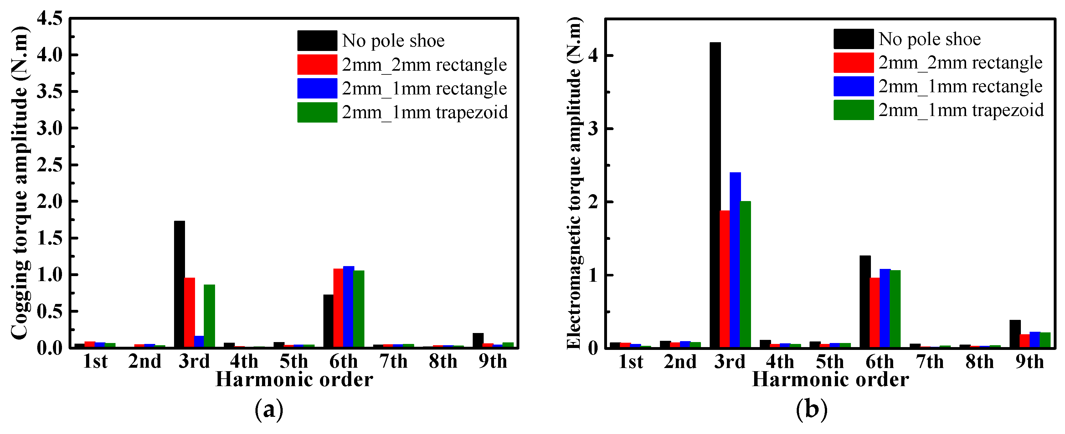
Figure 8a shows that the cogging torque of the motor with pole shoe is smaller than that of a motor without pole shoe. Figure 8b also shows that the torque ripple of a motor with pole shoe is smaller than that of a motor without pole shoe. When the pole shoe combination is “2 mm_1 mm rectangle”, the cogging torque of the motor is the minimum. When the pole shoe combination is “2 mm_2 mm rectangle”, the torque ripple 25.47% of motor is the minimum. Moreover, when the pole shoe combination is “2 mm_1 mm trapezoid”, the torque ripple of motor is 26.98%, which is close to the minimum value. Using Fast Fourier Transform (FFT) to analyze cogging torque and electromagnetic torque, and transform period is based on the back-EMF period, the amplitude of each harmonic is shown in Figure 9.
The FFT results of cogging torque and electromagnetic torque show that the main harmonics of all combinations are the 3rd order, the 6th order and the 9th order. The 6th harmonic amplitude of cogging torque and electromagnetic torque of all combinations is close. In the motor without pole shoe, the 3rd harmonic amplitude is notably higher than that of the motor with pole shoe. Except for the motors whose pole shoe combinations are “2 mm_2 mm rectangle” and “2 mm_1 mm trapezoid”, the 3rd harmonic amplitude of electromagnetic torque in motors whose pole shoe is other combinations is much larger than twice that of cogging torque. Therefore, it can be deduced that the armature reaction of motors whose pole shoe combinations are “2 mm_2 mm rectangle” and “2 mm_1 mm trapezoid” is slight. Furthermore, the average torque and slot area of motor whose pole shoe combination is “2 mm_1 mm trapezoid” are larger than that of motor whose pole shoe combination is “2 mm_2 mm rectangle”. Based on the above comparison results, “2 mm_1 mm trapezoid” is chosen as the pole shoe scheme.
4.2. Rotor Pole Arc Coefficient
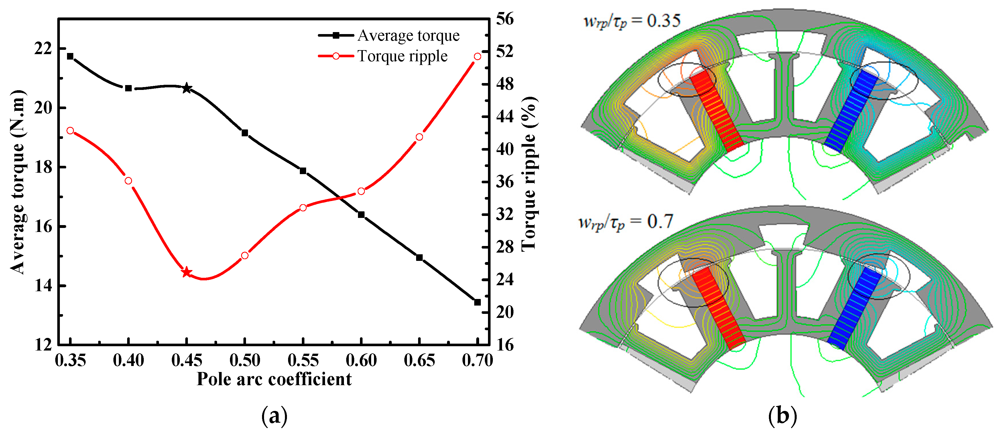
The rotor pole arc coefficient is equal to wrp/τp, which varies from 0.35 to 0.7 when the rotor pole pitch τp is constant. Variation of average torque and torque ripple is shown in Figure 10a. With increasing rotor pole arc coefficient, the torque ripple is first decreased and then increased. The average torque is reduced because the flux leakage of the magnet outer radius becomes more and more serious, as shown in Figure 10b. In order to obtain a torque ripple as low as possible and average torque as large as possible, the rotor pole arc coefficient is chosen as 0.45, whose torque ripple is reduced to 24.92% and average torque is 20.66 N·m.
4.3. “V”-Shaped Laminated Segment Tooth Width
The no-load back-EMF waveform of winding A after the above optimizations is shown in Figure 11a. It can be seen that the distortion of no-load back-EMF is serious. Consequently, it leads to torque harmonics when a sinusoidal current is fed into the windings, which is one of the main reasons causing high torque ripple. The magnetic flux lines of module MA are shown in Figure 11b, where it can be found that the positive magnetic flux path and the negative magnetic flux path are not completely symmetrical, which results in distortion of the coil no-load back-EMF. In order not to reduce the stator slot area, the tooth width of the “V”-shaped laminated segments that adjoin with non-magnetic blocks is reduced to improve the symmetry of the magnetic flux path, and the reduced width Vtw is optimized. Total harmonic distortion (THD) variation of the no-load back-EMF with increasing Vtw is shown in Figure 12a. It is first decreased and then increased, reaching the minimum value when Vtw is 2.75 mm. Average torque and torque ripple with increasing Vtw are shown in Figure 12b. Average torque is reduced, torque ripple is first decreased and then increased, reaching the minimum value when Vtw is 2.0 mm. The THD is just slightly greater than the minimum value when Vtw is 2.0 mm, and its average torque is larger than that when Vtw is 2.75 mm. Hence, the reduced width Vtw is chosen as 2.0 mm, whose torque ripple is reduced to 15.61%, THD of no-load back-EMF is reduced from 19.67 to 10.84% by 44.89%.
4.4. Analysis and Discussion
The cogging torque, average electromagnetic torque, and torque ripple of the initial motor and optimized motor are compared in Table 3. It can be seen that stator pole shoe, rotor pole arc coefficient, and tooth width of “V”-shaped laminated segments all have significant influences on cogging torque, electromagnetic torque, and torque ripple. Therefore, these parameters should be carefully chosen in the original design. After optimizations, it reduces the cogging torque by 20.43% and torque ripple by 66.84% but the average torque loss is only 1.80%.
5. Comparison of the MSOR-FSPM Motor and COR-FSPM Motor
5.1. Parameters of the MSOR-FSPM Motor and COR-FSPM Motor
Although the operation principle of the MSOR-FSPM motor is the same as that of the COR-FSPM motor, the magnetic flux path of each phase and some properties have been changed. In order to evaluate the utilization of PM, the average electromagnetic torque of the two motors are compared. Several rules must be observed to make the comparison results fair: (1) outside diameter, air gap length, and stack length of both motors are the same; (2) material properties of each part are the same; (3) current density of both motors is the same; (4) phase current value of both motors is the same. The cross-sectional views of both motors are shown as Figure 13. Except the partial parameters shown in Table 4, the other main design parameters of both motors are the same with Table 1.
5.2. Analysis of Theory and Magnetic Circuit
Figure 14, Figure 15, Figure 16 and Figure 17 show the no-load magnetic field distributions and the local magnetic circuits of MSOR-FSPM motor and COR-FSPM motor at two typical rotor positions, where the PM flux linkage of phase A reaches the positive extreme value and the negative extreme value, respectively. Considering the periodicity of the magnetic flux along the circumference, only the magnetic flux circuits of phase A with markings in these Figures are analyzed.
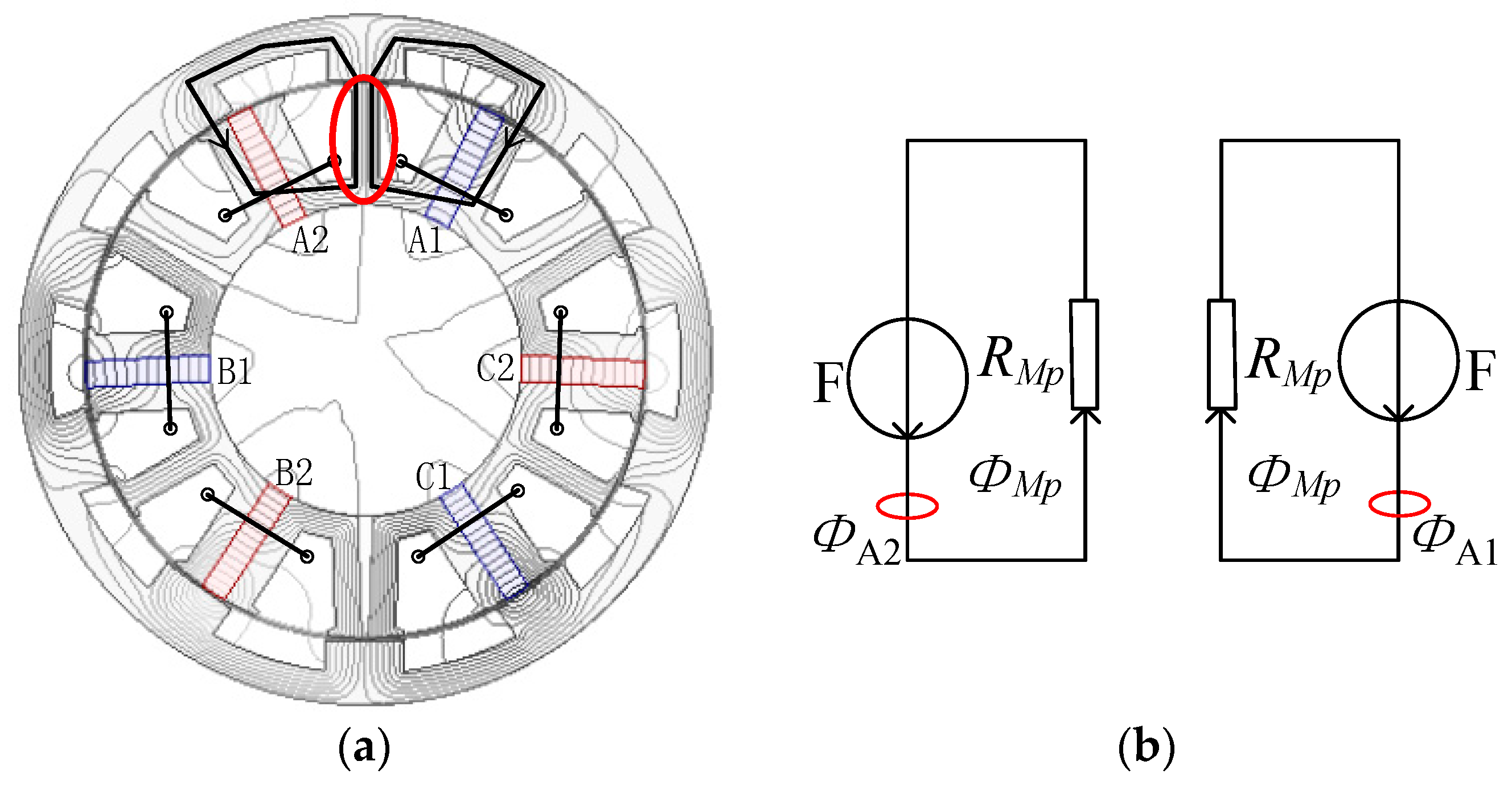
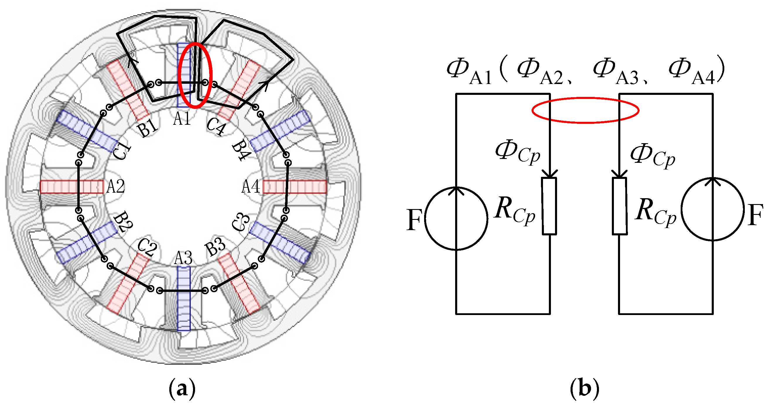
As is seen from Figure 14a, the magnetic flux produced by PMA1 and PMA2 in MSOR-FSPM motor are added at the middle tooth of “W”-shaped laminated segment and the width of the magnetic flux path for one PM is half of this tooth. The corresponding equivalent magnetic circuit is shown in Figure 14b. As is seen from Figure 15a, the magnetic flux produced by PMA1 and PMC4 in the COR-FSPM motor are added at the right end tooth of the stator pole, which is surrounded by winding A1, and the width of the magnetic flux path for one PM is half of this tooth. The corresponding equivalent magnetic circuit is shown in Figure 15b. Therefore, the magnetoresistance of MSOR-FSPM motor and COR-FSPM motor in the equivalent magnetic circuits is almost equal to each other, i.e.,
where RMp is the magnetoresistance of the equivalent magnetic circuit in the MSOR-FSPM motor, and RCp is the magnetoresistance of the equivalent magnetic circuit in the COR-FSPM motor.
If the magnetomotive force per PM is defined as Fm, the positive extreme value of phase A flux linkage produced by PMs in the MSOR-FSPM motor and COR-FSPM motor can be obtained by Equations (14) and (15), respectively.
where ΨM_phaseA_p is the positive extreme value of phase A flux linkage produced by PMs in the MSOR-FSPM motor, ΨC_phaseA_p is the positive extreme value of phase A flux linkage produced by PMs in the COR-FSPM motor, NM_coil is the number of turns per coil in the MSOR-FSPM motor, NC_coil is the number of turns per coil in the COR-FSPM motor, ΦMp is the positive extreme value of PM flux in the MSOR-FSPM motor, ΦCp is the positive extreme value of PM flux in the COR-FSPM motor.
It can be seen from Equations (14) and (15) that ΨM_phaseA_p is about 50% of ΨC_phaseA_p. However, this relationship is not suitable for the negative extreme value of flux linkage produced by PMs in both motors. As is seen from Figure 16a, the magnetic flux produced by PMA1 and PMA2 in the MSOR-FSPM motor are independent, and the width of the magnetic flux path for one PM is the tooth width. The corresponding equivalent magnetic circuit is shown in Figure 16b. As is seen from Figure 17a, the magnetic flux produced by PMA1 and PMB1 in the COR-FSPM motor are added at the left end tooth of the stator pole, which is surrounded by winding A1, and the width of the magnetic flux path for one PM is half of this tooth. The corresponding equivalent magnetic circuit is shown in Figure 17b. The saturation degree of the MSOR-FSPM motor is greatly changed. The magnetoresistance of the MSOR-FSPM motor in the equivalent magnetic circuit is far less than that of the COR-FSPM motor, and it is close to 50% that of the COR-FSPM motor, i.e.,
where RMn is the magnetoresistance of the equivalent magnetic circuit in the MSOR-FSPM motor, and RCn is the magnetoresistance of the equivalent magnetic circuit in the COR-FSPM motor.
The negative extreme value of phase A flux linkage produced by PMs in the MSOR-FSPM motor and the COR-FSPM motor can be obtained by Equations (17) and (18), respectivelyL
where ΨM_phaseA_n is the negative extreme value of phase A flux linkage produced by PMs in the MSOR-FSPM motor, ΨC_phaseA_n is the negative extreme value of phase A flux linkage produced by PMs in the COR-FSPM motor, ΦMn is the negative extreme value of PM flux in the MSOR-FSPM motor, ΦCn is the negative extreme value of PM flux in the COR-FSPM motor. It can be seen from Equations (17) and (18) that ΨM_phaseA_n is close to 100% of ΨC_phaseA_n. Based on the above analysis, the average PM flux linkage produced by PMs in the MSOR-FSPM motor is close to 75% of that in the COR-FSPM motor, even if the volume of PMs in the MSOR-FSPM motor is about half of that in the COR-FSPM motor. When the same vector control is adopted, the average electromagnetic torque in the MSOR-FSPM motor could be close to 75% of that in the COR-FSPM motor.
5.3. Validation by FEM
The results of theoretical analysis are verified by the FEM. No-load PM flux linkage waveforms of phase A and their FFT results calculated by the Maxwell 2D FEM software are shown in Figure 18. Since the reluctance torque Trm in the FSPM motor can be eliminated by adopting vector control of id = 0, the average electromagnetic torque of the FSPM motor in d-q coordinate system can be calculated from Equation (19):
where ΨPM_d is the amplitude of PM flux linkage, Im is the amplitude of phase current.
For these two motors, Nr is equal to 10 and Im is equal to 15.4 A. ΨPM_d of the MSOR-FSPM motor, and the COR-FSPM motor are 0.09586 Wb and 0.12039 Wb, respectively. Even if the PM volume of the MSOR-FSPM motor is only 54.04% of that in the COR-FSPM motor, the amplitude of the fundamental flux linkage in the MSOR-FSPM motor is about 79.62% of that in the COR-FSPM motor. Based on the fundamental flux linkage, the corresponding average electromagnetic torque of the MSOR-FSPM motor calculated indirectly by Equation (19) is 22.14 N·m and that of the COR-FSPM motor is 27.81 N·m.
The electromagnetic torque waveforms calculated directly by Maxwell 2D are shown in Figure 19. Their average torques are 20.97 N·m for the MSOR-FSPM motor and 27.61 N·m for the COR-FSPM motor. The average electromagnetic torque of the MSOR-FSPM motor is 75.95% of that in the COR-FSPM motor, which is close to the theoretical value of 75%. Compared with the results of Maxwell 2D, the errors of average electromagnetic torque in the MSOR-FSPM motor and COR-FSPM motor calculated indirectly by Equation (19) are 5.58% and 0.72%, respectively. The reason for the errors is that the influences of harmonic component on average torque are neglected when Equation (19) is adopted. For the COR-FSPM motor, the ratio of fundamental wave and other harmonics is 99.27:0.73, the influences of harmonic component on average electromagnetic torque are small and the average electromagnetic torque based on Equation (19) is almost equal to the Maxwell 2D result. For the MSOR-FSPM motor, the ratio of fundamental wave and other harmonics is 89.37:10.63. The harmonic component is higher than that of the COR-FSPM motor, and the error of the average electromagnetic torque calculated indirectly by Equation (19) is larger than that in the COR-FSPM motor. However, both the calculation and Maxwell 2D results show that the average electromagnetic torque of the MSOR-FSPM motor is far larger than half that of the COR-FSPM motor, even if the PM volume in the MSOR-FSPM motor is about half of that in the COR-FSPM motor, which verifies the results of our theoretical analysis.
However, the above comparison is based on the same number of turns per phase. Actually, the slot area per phase of the MSOR-FSPM motor is enlarged because of the reduction of PMs, and its stator slot fill factor is smaller than that of the COR-FSPM motor. The average electromagnetic torque in the MSOR-FSPM motor is calculated when the stator slot fill factor of the MSOR-FSPM motor is the same as that of the COR-FSPM motor. The compared performances of the three motors are shown as Table 5, in which MSOR-FSPM-1 motor has the same number of turns per phase as the COR-FSPM motor and MSOR-FSPM-2 motor has the same stator slot fill factor as the COR-FSPM motor. It can be seen that the average electromagnetic torque in the MSOR-FSPM motor is further enlarged to 86.53% of that in the COR-FSPM motor when they have the same stator slot fill factor. The PM utilization in the MSOR-FSPM motor is further improved.
5.4. Inductance of the MSOR-FSPM Motor and COR-FSPM Motor
The waveforms of self-inductance and mutual-inductance in the MSOR-FSPM motor and COR-FSPM motor are shown in Figure 20. The inductance characteristics of the COR-FSPM motor are the same as the conventional FSPM motor where the self-inductance and mutual-inductance change twice in one electrical period, and the average self-inductance value is equal to two times that of mutual-inductance. But for the MSOR-FSPM motor, self-inductance and mutual-inductance change once in one electrical period, and the average self-inductance value is far more than two times that of mutual-inductance.
It is worth noting that the self-inductance is increased and mutual-inductance is reduced when a module stator is adopted. The self-inductance of the MSOR-FSPM motor is larger than two times that of the COR-FSPM motor, and mutual-inductance is smaller than half that of the COR-FSPM motor. When an open circuit occurs in one phase in the MSOR-FSPM motor, the remaining two-phase windings have greater potential to continue to work due to the smaller mutual-inductance. When a short circuit occurs in one phase, the short-circuit current of the MSOR-FSPM motor is smaller than that of the COR-FSPM motor due to the larger self-inductance. Therefore, it is deduced that the fault tolerance capability of the MSOR-FSPM motor is better than that of the COR-FSPM motor.
6. Conclusions
A novel MSOR-FSPM motor with modular stator structure is researched in this paper. The motor structure is illustrated in great detail, and its operation and design principles are explained. The influences of rotor pole number on motor torque characteristics are discussed. The MSOR-FSPM motor topology with 12-slot/10-pole is chosen to be researched further due to the minimum and period cogging torque. The magnetic performances of the MSOR-FSPM motor are optimized from the aspects of stator pole shoe, rotor pole arc coefficient, and the tooth width of “V”-shaped laminated segments. After optimizations, the torque ripple is reduced from 46.63 to 15.61% or 66.52%, and average electromagnetic torque is only reduced from 19.97 N·m to 19.61 N·m or 1.80%. Finally, utilization of PM in the MSOR-FSPM motor and COR-FSPM motor is analyzed from the point of view of the magnetic flux path. It is verified by FEM results. Even if the PM volume in the MSOR-FSPM motor is 54.04% of that in the COR-FSPM motor, when they have the same number of turns per phase, the average electromagnetic torque of the MSOR-FSPM motor is more than 75% of that in the COR-FSPM motor; when they have the same stator slot fill factor, the average electromagnetic torque of the MSOR-FSPM motor can reach 86.53% of that in the COR-FSPM motor. It is thus indicated that the utilization of PM in the MSOR-FSPM motor is much improved by adopting the proposed modular stator. This paper is mainly concerned with the design principles and fundamental theoretical research of a new outer-rotor FSPM motor topology, which provides good references for the prototype manufacturing and further research.
Acknowledgments
This work was supported in part by the National Natural Science Foundation of China under Projects 51677005.
Author Contributions
All authors contributed to this work by collaboration. Jing Zhao is the main author of this manuscript; Yun Zheng assisted to establish the finite element model and perform the simulations; Congcong Zhu, Xiangdong Liu and Bin Li provided some useful suggestions in the construction of paper. All authors revised and approved the publication.
Conflicts of Interest
The authors declare no conflict of interest.
References
- Chau, K.T.; Chan, C.C.; Liu, C. Overview of permanent-magnet brushless drives for electric and hybrid electric vehicles. IEEE Trans. Ind. Electron. 2008, 55, 2246–2257. [Google Scholar] [CrossRef]
- Zhu, X.Y.; Chen, L.; Li, Q.; Sun, Y.B.; Hua, W.; Wang, Z. A New Magnetic-Planetary-Geared Permanent Magnet Brushless Machine for Hybrid Electric Vehicle. IEEE Trans. Magn. 2012, 48, 4642–4645. [Google Scholar] [CrossRef]
- Ghariani, M.; Hachicha, M.R.; Ltifi, A.; Bensalah, I.; Ayadi, M.; Neji, R. Sliding mode control and neuro-fuzzy network observer for induction motor in EVs applications. Int. J. Electr. Hybrid Veh. 2011, 3, 20–46. [Google Scholar] [CrossRef]
- Arkkiol, A.; Jokinen, T.; Lantto, E. Design, simulation and construction of two synchronized DC motors’ driver for EVs. IEEE Trans. Electr. Mach. Syst. 2005, 2, 871–876. [Google Scholar]
- Pellegrino, G.; Vagati, A.; Boazzo, B.; Guglielmi, P. Comparison of induction and PM synchronous motor drives for EV application including design examples. IEEE Trans. Ind. Appl. 2012, 48, 2322–2332. [Google Scholar] [CrossRef]
- Zhu, X.Y.; Cheng, M.; Zhao, W.X.; Liu, C.H.; Chau, K.T. A transient cosimulation approach to performance analysis of hybrid excited doubly salient machine considering indirect field-circuit coupling. IEEE Trans. Magn. 2007, 43, 2558–2560. [Google Scholar] [CrossRef]
- Deodhar, R.P.; Andersson, S.; Boldea, I.; Miller, T.J.E. The flux-reversal machine: A new brushless doubly-salient permanent-magnet machine. IEEE Trans. Ind. Appl. 1997, 33, 925–934. [Google Scholar] [CrossRef]
- Li, D.W.; Qu, R.H.; Li, J.; Xu, W.; Wu, L.L. Synthesis of Flux Switching Permanent Magnet Machines. IEEE Trans. Energy Convers. 2016, 31, 1447–1453. [Google Scholar] [CrossRef]
- Abdollahi, S.E.; Vaez-Zadeh, S. Back-EMF analysis of a novel linear flux switching motor with segmented secondary. IEEE Trans. Magn. 2014, 50, 1–9. [Google Scholar] [CrossRef]
- Hua, W.; Zhu, Z.Q.; Cheng, M.; Pang, Y.; Howe, D. Comparison of Flux-Switching and Doubly-Salient Permanent Magnet Brushless Machines. In Proceedings of the Eighth International Conference on Electrical Machines and Systems (ICEMS 2005), Nanjing, China, 27–29 September 2005; pp. 165–170. [Google Scholar]
- Sulaiman, E.; Kosaka, T.; Matsui, N. Parameter optimization study and performance analysis of 6S-8P permanent magnet flux switching machine with field excitation for high speed hybrid electric vehicles. In Proceedings of the 2011 14th European Conference on Power Electronics and Applications (EPE 2011), Birmingham, UK, 30 August–1 September 2011; pp. 1–9. [Google Scholar]
- Rauch, S.E.; Johnson, L.J. Design principles of flux-switching alternators. Trans. Ame. Inst. Electr. Eng. Part III Power Appar. Syst. 1995, 74, 1261–1268. [Google Scholar]
- Zhu, Z.Q.; Chen, J.T.; Pang, Y.; Howe, D.; Iwasaki, S.; Deodhar, R. Analysis of a Novel Multi-Tooth Flux-Switching PM Brushless AC Machine for High Torque Direct-Drive Applications. IEEE Trans. Magn. 2008, 44, 4313–4316. [Google Scholar] [CrossRef]
- Fei, W.Z.; Luk, P.C.K.; Shen, J.X. Torque Analysis of Permanent-Magnet Flux Switching Machines with Rotor Step Skewing. IEEE Trans. Magn. 2012, 48, 2664–2673. [Google Scholar] [CrossRef]
- Zulu, A.; Mecrow, B.C.; Armstrong, M. A Wound-Field Three-Phase Flux-Switching Synchronous Motor with All Excitation Sources on the Stator. IEEE Trans. Ind. Appl. 2010, 46, 2363–2371. [Google Scholar] [CrossRef]
- Hua, W.; Zhang, G.; Cheng, M. Flux-Regulation Theories and Principles of Hybrid-Excited Flux-Switching Machines. IEEE Trans. Ind. Electron. 2015, 62, 5359–5369. [Google Scholar] [CrossRef]
- Yu, F.; Cheng, M.; Chau, K.T.; Li, F. Control and Performance Evaluation of Multiphase FSPM Motor in Low-Speed Region for Hybrid Electric Vehicles. Energies 2015, 8, 10335–10353. [Google Scholar] [CrossRef]
- Aboelhassan, M.O.E.; Raminosoa, T.; Goodman, A.; Lillo, L.D.; Gerada, C. Performance Evaluation of a Vector-Control Fault-Tolerant Flux-Switching Motor Drive. IEEE Trans. Ind. Electron. 2013, 60, 2997–3006. [Google Scholar] [CrossRef]
- Mao, Y.X.; Liu, G.H.; Zhao, W.X.; Ji, J.H. Vibration prediction in fault-tolerant flux-switching permanent-magnet machine under healthy and faulty conditions. IET Electr. Power Appl. 2017, 11, 19–28. [Google Scholar] [CrossRef]
- Zhao, J.; Yan, Y.S.; Li, B.; Liu, X.D.; Chen, Z. Influence of Different Rotor Teeth Shapes on the Performance of Flux Switching Permanent Magnet Machines Used for Electric Vehicles. Energies 2014, 7, 8056–8075. [Google Scholar] [CrossRef]
- Ehsani, M.; Gao, Y.; Miller, J.M. Hybrid electric vehicles: Architecture and motor drives. IEEE Proc. 2007, 95, 719–728. [Google Scholar] [CrossRef]
- Wang, Y.; Jin, M.J.; Shen, J.X.; Fei, W.Z.; Luk, P.C.K. An Outer-Rotor Flux-Switching Permanent Magnet Motor for Traction Applications. In Proceedings of the 2010 IEEE Energy Conversion Congress and Exposition (ECCE 2010), Atlanta, GA, USA, 12–16 September 2010; pp. 1723–1730. [Google Scholar]
- Fei, W.Z.; Luk, P.C.K.; Shen, J.X.; Wang, Y.; Jin, M.J. A Novel Permanent-Magnet Flux Switching Machine with an Outer-Rotor Configuration for In-Wheel Light Traction Applications. IEEE Trans. Ind. Appl. 2012, 48, 1496–1506. [Google Scholar] [CrossRef]
- Zhu, X.Y.; Xiang, Z.X.; Zhang, C.; Quan, L.; Du, Y.; Gu, W.W. Co-Reduction of Torque Ripple for Outer Rotor Flux-Switching PM Motor Using Systematic Multi-Level Design and Control Schemes. IEEE Trans. Ind. Electron. 2017, 64, 1102–1112. [Google Scholar] [CrossRef]
- Hua, W.; Zhang, H.L.; Cheng, M.; Meng, J.J.; Hou, C. An Outer-Rotor Flux-Switching Permanent-Magnet-Machine with Wedge-Shaped Magnets for In-Wheel Light Traction. IEEE Trans. Ind. Electron. 2017, 64, 69–80. [Google Scholar] [CrossRef]
- Ahmad, M.Z.; Sulaiman, E.; Haron, Z.A.; Kosaka, T. Preliminary Studies on a New Outer-Rotor Permanent Magnet Flux Switching Machine with Hybrid Excitation Flux for Direct Drive EV Applications. In Proceedings of the 2012 IEEE International Conference on Power and Energy (PEcon 2012), Kota Kinabalu, Malaysia, 2–5 December 2012; pp. 928–933. [Google Scholar]
- Zhu, X.Y.; Shu, Z.M.; Quan, L.; Xiang, Z.X.; Pan, X.Q. Multi-Objective Optimization of an Outer-Rotor V-Shaped Permanent Magnet Flux Switching Motor Based on Multi-Level Design Method. IEEE Trans. Magn. 2016, 52, 8205508. [Google Scholar] [CrossRef]
- Hua, W.; Cheng, M.; Zhu, Z.Q.; Howe, D. Design of Flux-Switching Permanent Magnet Machine Considering the Limitation of Inverter and Flux-Weakening Capability. In Proceedings of the 2006 IEEE Industry Applications Conference/Forty-First IAS Annual Meeting, Tampa, FL, USA, 8–12 October 2006; pp. 2403–2410. [Google Scholar]
- Liu, X.D.; Gu, Z.X.; Zhao, J. Torque ripple reduction of a novel modular arc-linear flux-switching permanent-magnet motor with rotor step skewing. Energies 2016, 9, 404–421. [Google Scholar] [CrossRef]
- Sikder, C.; Husain, I.; Wen, O. Cogging Torque Reduction in Flux-Switching Permanent-Magnet Machines by Rotor Pole Shaping. IEEE Trans. Ind. Appl. 2015, 51, 3609–3619. [Google Scholar] [CrossRef]
Figure 1.
Structure of the MSOR-FSPM motor: (a) 3D structure of the MSOR-FSPM motor; (b) Cross-sectional view of the MSOR-FSPM motor.
Figure 1.
Structure of the MSOR-FSPM motor: (a) 3D structure of the MSOR-FSPM motor; (b) Cross-sectional view of the MSOR-FSPM motor.

Figure 2.
Distributions of the main magnetic flux lines in module MA.

Figure 3.
Waveforms of PM flux linkage, no-load back-EMF, and phase current.

Figure 4.
12-slot/20-pole MSOR-FSPM motor: (a) Cross-sectional view of the 12-slot/20-pole MSOR-FSPM motor; (b) No-load back-EMF waveforms of coil A1, coil A2, and winding A.
Figure 4.
12-slot/20-pole MSOR-FSPM motor: (a) Cross-sectional view of the 12-slot/20-pole MSOR-FSPM motor; (b) No-load back-EMF waveforms of coil A1, coil A2, and winding A.

Figure 5.
12-slot/10-pole MSOR-FSPM motor: (a) Cross-sectional view of the 12-slot/10-pole MSOR-FSPM motor; (b) No-load back-EMF waveforms of coil A1, coil A2, and winding A.
Figure 5.
12-slot/10-pole MSOR-FSPM motor: (a) Cross-sectional view of the 12-slot/10-pole MSOR-FSPM motor; (b) No-load back-EMF waveforms of coil A1, coil A2, and winding A.

Figure 6.
No-load performances of different MSOR-FSPM motors: (a) No-load back-EMF waveforms of winding A; (b) Cogging torque waveforms.
Figure 6.
No-load performances of different MSOR-FSPM motors: (a) No-load back-EMF waveforms of winding A; (b) Cogging torque waveforms.

Figure 7.
Main optimized parameters of 12S/10P MSOR-FSPM motor.

Figure 8.
Cogging torque and electromagnetic torque: (a) Cogging torque of 12S/10P MSOR-FSPM motor; (b) Electromagnetic torque of 12S/10P MSOR-FSPM motor.
Figure 8.
Cogging torque and electromagnetic torque: (a) Cogging torque of 12S/10P MSOR-FSPM motor; (b) Electromagnetic torque of 12S/10P MSOR-FSPM motor.

Figure 9.
FFT results of cogging torque and electromagnetic torque: (a) Amplitude of each harmonic in cogging torque; (b) Amplitude of each harmonic in electromagnetic torque.
Figure 9.
FFT results of cogging torque and electromagnetic torque: (a) Amplitude of each harmonic in cogging torque; (b) Amplitude of each harmonic in electromagnetic torque.

Figure 10.
Average torque, torque ripple and flux leakage of magnet outer radius: (a) Average torque and torque ripple with increasing rotor pole arc coefficient; (b) the flux leakage of magnet outer radius in module MA.
Figure 10.
Average torque, torque ripple and flux leakage of magnet outer radius: (a) Average torque and torque ripple with increasing rotor pole arc coefficient; (b) the flux leakage of magnet outer radius in module MA.

Figure 11.
No-load back-EMF waveform and magnetic flux lines: (a) No-load back-EMF waveform of winding A; (b) Magnetic flux lines of module MA.
Figure 11.
No-load back-EMF waveform and magnetic flux lines: (a) No-load back-EMF waveform of winding A; (b) Magnetic flux lines of module MA.

Figure 12.
THD, average torque and torque ripple: (a) THD of no-load back-EMF with increasing Vtw; (b) Average torque and torque ripple with increasing Vtw.
Figure 12.
THD, average torque and torque ripple: (a) THD of no-load back-EMF with increasing Vtw; (b) Average torque and torque ripple with increasing Vtw.

Figure 13.
Cross-sectional views: (a) Cross-sectional view of MSOR-FSPM motor; (b) Cross-sectional view of COR-FSPM motor.
Figure 13.
Cross-sectional views: (a) Cross-sectional view of MSOR-FSPM motor; (b) Cross-sectional view of COR-FSPM motor.
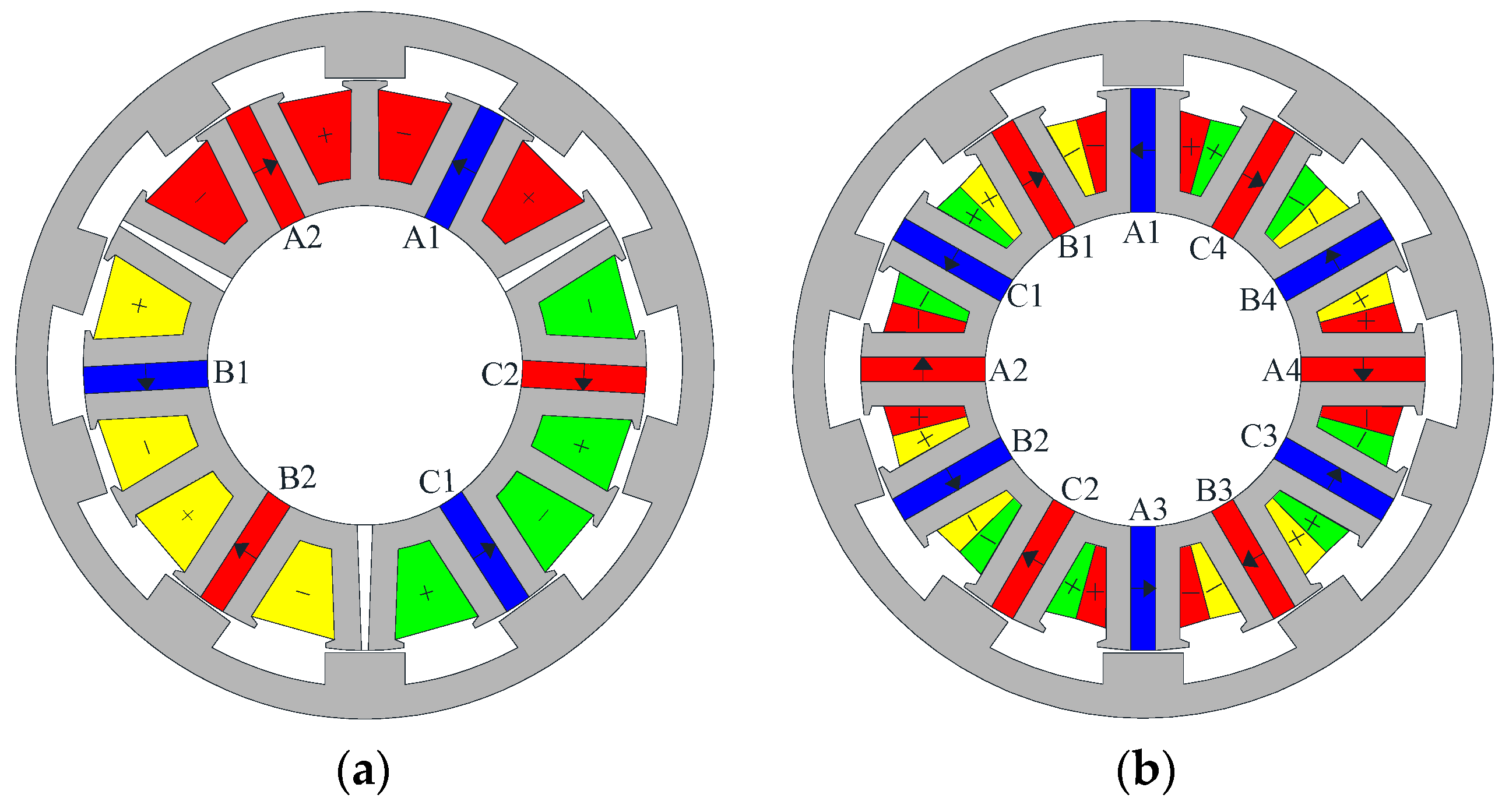
Figure 14.
Positive extreme value of phase A flux linkage produced by PMs in MSOR-FSPM motor: (a) No-load magnetic field distributions; (b) Local equivalent magnetic circuit.
Figure 14.
Positive extreme value of phase A flux linkage produced by PMs in MSOR-FSPM motor: (a) No-load magnetic field distributions; (b) Local equivalent magnetic circuit.

Figure 15.
Positive extreme value of phase A flux linkage produced by PMs in COR-FSPM motor: (a) No-load magnetic field distributions; (b) Local equivalent magnetic circuit.
Figure 15.
Positive extreme value of phase A flux linkage produced by PMs in COR-FSPM motor: (a) No-load magnetic field distributions; (b) Local equivalent magnetic circuit.

Figure 16.
Negative extreme value of phase-A flux linkage produced by PMs in MSOR-FSPM motor: (a) No-load magnetic field distributions; (b) Local equivalent magnetic circuit.
Figure 16.
Negative extreme value of phase-A flux linkage produced by PMs in MSOR-FSPM motor: (a) No-load magnetic field distributions; (b) Local equivalent magnetic circuit.

Figure 17.
Negative extreme value of phase A flux linkage produced by PMs in COR-FSPM motor: (a) No-load magnetic field distributions; (b) Local equivalent magnetic circuit.
Figure 17.
Negative extreme value of phase A flux linkage produced by PMs in COR-FSPM motor: (a) No-load magnetic field distributions; (b) Local equivalent magnetic circuit.
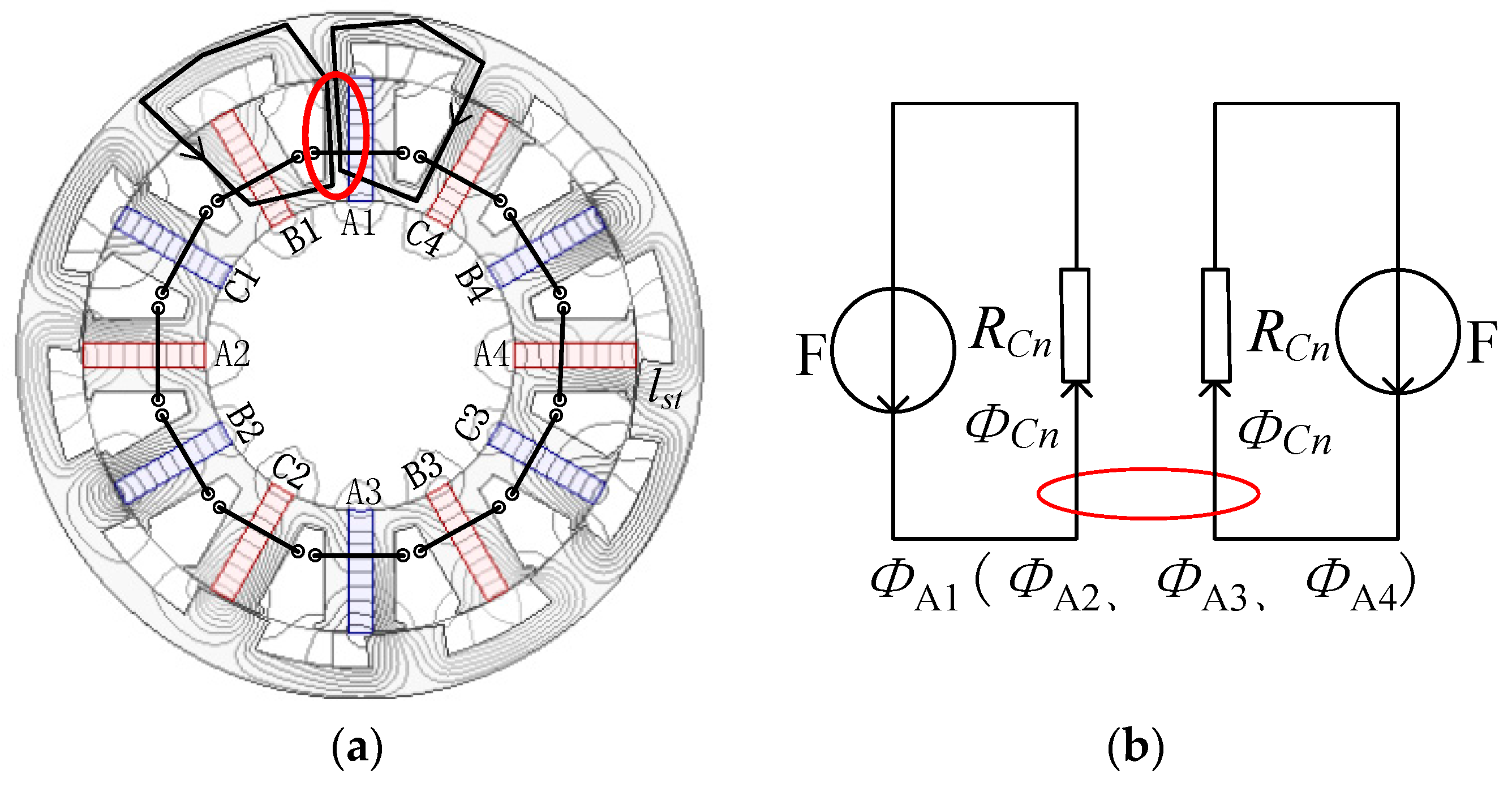
Figure 18.
No-load flux linkage waveforms and FFT results of no-load flux linkage: (a) No-load flux linkage waveforms of phase A; (b) FFT results of phase A no-load flux linkage.
Figure 18.
No-load flux linkage waveforms and FFT results of no-load flux linkage: (a) No-load flux linkage waveforms of phase A; (b) FFT results of phase A no-load flux linkage.

Figure 19.
Electromagnetic torque waveforms of the MSOR-FSPM motor and COR-FSPM motor.

Figure 20.
Waveforms of self-inductance and mutual-inductance in the MSOR-FSPM motor and COR-FSPM mot
Figure 20.
Waveforms of self-inductance and mutual-inductance in the MSOR-FSPM motor and COR-FSPM mot


Table 1.
Main parameters of the initial designed 12-slot/10-pole MSOR-FSPM motor.
| Symbol | Machine Parameter | MSOR-FSPM | Unit |
|---|---|---|---|
| m | Phase number | 3 | |
| Ns | Number of stator poles | 12 | |
| Nr | Number of rotor poles | 10 | |
| α | Rotor pole arc coefficient | 0.5 | |
| Ncoil | Number of turns per coil | 70 | |
| PM | Magnet material | NTP40UH | |
| n | Base speed | 800 | r/min |
| Pout | Based output power | 1.5 | kW |
| Dro | Rotor outer diameter | 155 | mm |
| Dsi | Stator inner diameter | 70 | mm |
| Dso | Stator outer diameter | 125 | mm |
| wst | Stator tooth width | 5.5 | mm |
| lef | Motor active length | 100 | mm |
| hrp | Rotor pole height | 7.5 | mm |
| hry | Rotor yoke height | 7 | mm |
| wrp | Rotor pole width | 19.8 | mm |
| lg | Air gap length | 0.5 | mm |
| Br | Magnet remanence (20 °C) | 1.26 | T |
| Ismax | Rated current amplitude | 15.4 | A |
Table 2.
Different parameters of MSOR-FSPM motors.
| Main Parameter | 10P | 11P | 22P | 23P |
|---|---|---|---|---|
| τc (°) | 36 | 32.73 | 32.72 | 31.30 |
| τm (°) | 54 | 49.09 | 57.27 | 54.78 |
| τd (°) | 120 | 120 | 120 | 120 |
| τp (°) | 36 | 32.73 | 16.36 | 15.65 |
| n | 1 | 1 | 2 | 2 |
| i | 1 | 1 | 3 | 3 |
| j | 3 | 3 | 7 | 7 |
| l | 0 | 1 | 0 | 1 |
Table 3.
Torque performances in the initial motor and the optimized motor.
| Performance | Initial Motor | hw, hh = “2 mm_1 mm Trapezoid“ | wrp/τp = 0.45 | Vtw = 2.0 mm | Optimized Motor |
|---|---|---|---|---|---|
| Cogging torque (N·m) | 4.60 | 3.64 | 5.29 | 3.66 | 3.66 |
| Average electromagnetic torque (N·m) | 19.97 | 19.15 | 20.66 | 19.61 | 19.61 |
| Torque ripple (%) | 47.08 | 26.98 | 24.92 | 15.61 | 15.61 |
Table 4.
Partial parameters of MSOR-FSPM motor and COR-FSPM motor.
| Symbol | Machine Parameter | MSOR-FSPM | COR-FSPM | Unit |
|---|---|---|---|---|
| α | Rotor pole arc coefficient | 0.45 | ||
| wrp | Rotor pole width | 17.8 | mm | |
| ht | Pole shoe thickness | 2 | mm | |
| hw | Pole shoe width | 2 | mm | |
| hh | Pole shoe height | 1 | mm | |
| Ncoil | Number of turns per coil | 70 | 35 | |
| Sslot | Area per phase | 955.44 | 785.28 | mm2 |
| Vpm | Volume of PMs | 97,185 | 179,850 | mm2 |
Table 5.
Compared performances of the MSOR-FSPM motor and COR-FSPM motor.
| Performance | MSOR-FSPM-1 | MSOR-FSPM-2 | COR-FSPM |
|---|---|---|---|
| Ratio of PM volume (%) | 54.04 | 54.04 | 100 |
| ΨPM_d (Wb) | 0.09586 | 0.11092 | 0.12039 |
| Ratio of ΨPM_d (%) | 79.62 | 92.13 | 100 |
| Average torque calculated indirectly (N·m) | 22.14 | 25.62 | 27.81 |
| Ratio of average torque calculated indirectly (%) | 79.61 | 92.12 | 100 |
| Average torque calculated directly (N·m) | 20.97 | 23.98 | 27.61 |
| Ratio of average torque calculated directly (%) | 75.95 | 86.53 | 100 |
© 2017 by the authors. Licensee MDPI, Basel, Switzerland. This article is an open access article distributed under the terms and conditions of the Creative Commons Attribution (CC BY) license (http://creativecommons.org/licenses/by/4.0/).
Share and Cite
MDPI and ACS Style
Zhao, J.; Zheng, Y.; Zhu, C.; Liu, X.; Li, B. A Novel Modular-Stator Outer-Rotor Flux-Switching Permanent-Magnet Motor. Energies 2017, 10, 937. https://doi.org/10.3390/en10070937
AMA Style
Zhao J, Zheng Y, Zhu C, Liu X, Li B. A Novel Modular-Stator Outer-Rotor Flux-Switching Permanent-Magnet Motor. Energies. 2017; 10(7):937. https://doi.org/10.3390/en10070937
Chicago/Turabian StyleZhao, Jing, Yun Zheng, Congcong Zhu, Xiangdong Liu, and Bin Li. 2017. "A Novel Modular-Stator Outer-Rotor Flux-Switching Permanent-Magnet Motor" Energies 10, no. 7: 937. https://doi.org/10.3390/en10070937
Note that from the first issue of 2016, this journal uses article numbers instead of page numbers. See further details here.