
Numerical and Experimental Study on a Solar Water Heating System in Lhasa


1
National Centre for International Research of Low-carbon and Green Buildings, Ministry of Science & Technology, Chongqing University, Chongqing 400045, China
2
Joint International Research Laboratory of Green Buildings and Built Environments, Ministry of Education, Chongqing University, Chongqing 400045, China
*
Author to whom correspondence should be addressed.
Energies 2017, 10(7), 963; https://doi.org/10.3390/en10070963
Submission received: 9 April 2017
/
Revised: 6 July 2017
/
Accepted: 6 July 2017
/
Published: 10 July 2017
(This article belongs to the Special Issue Solar Technologies for Buildings)
Abstract
:Lhasa is a “solar city” with high altitude, located in a cold zone in China. Due to the lack of mineral energy sources and the fragility of its ecological environment, solar heating technology is the first choice to satisfy the demand of indoor thermal comfort for building heating. In this study, an accurate solar heating system in Lhasa was investigated under the simultaneous charging and discharging operation mode. Based on the solar heating system, a numerical calculation method of the tank temperature distribution under the simultaneous charging and discharging operation mode was proposed and validated by experiments. This numerical method offers a correlation between the output water temperatures of the tank and the input water temperatures of the tank, which can be used to optimize the thermal performance of the solar heating system in future studies. To evaluate the system performance under the simultaneous charging and discharging operation mode, the transient coefficient of performance (COP) of the heating system was calculated based on the experimental measurements. The calculated results showed that the system COP reached an average number of 3.0, which was nearly equal to that of gas-boiler heating system and much higher than that of electrical heating systems. A north-facing room and a south-facing room were both selected to test whether the room temperatures met the heating requirements. The test results showed that the north-facing room had an average temperature over 17 °C while the south-facing room was over 20 °C, which illustrated that a good heating effect was achieved. Although a relatively high system COP was shown with a good heating effect for the solar heating system under the simultaneous charging and discharging operation mode, further recommendations were proposed for the mass flow rates of the solar collecting cycles and control stagey of the fan coil unit (FCU).
1. Introduction
Lhasa is the provincial capital of Tibet (China). With an altitude of 3650 m and an annual average temperature of 8.1 °C it belongs to the cold plateau zone. As local mineral energy is scarce, with no proven reserves of coal, oil or gas in a 1000 km radius around Lhasa, its electricity supply mainly relies on hydroelectric and geothermal power. Moreover, the surrounding high mountains can impede the urban air circulation for self-cleaning. Therefore, its ecological environment is fragile [1]. However, the “solar city” Lhasa has the most abundant solar resource in China, with cumulative solar radiation up to 7.2 GJ/m2 per year and 2.56 GJ/m2 per winter. Thus the application of solar heating technology in Lhasa is promising, as it can contribute to the improvement in indoor thermal comfort, energy consumption reduction and more environmental friendliness [1,2,3].
Solar energy is one of the most promising renewable energy sources since it suitably meets sustainable development objectives and it can be exploited worldwide [4,5,6,7,8,9]. Buker et al. [10] reviewed the solar thermal applications in buildings, addressed the important issues related to architectural barriers, system design and installation and revealed the trend of solar thermal technologies required in the future. As solar energy is unstable and discontinuous, a heat storage unit is an indispensable component to ensure the reliable and efficient operation of the solar heating systems [11,12]. Solar water storage tanks are widely used for solar heating systems due to their low cost and convenience [13,14,15]. The temperature distribution of the solar water storage tank is key to the design and operation of a solar heating system [16,17,18,19,20], and mathematical models are essential for the analysis of the temperature distribution in the heat storage tank [21,22,23]. One-dimensional finite volume discretization is the most common model of a stratified storage tank [24,25,26,27,28,29,30], which greatly reduces the model complexity but thus implies that three dimensional effects, like jet mixing and buoyancy, require model adaptations or correlations [31]. Two-dimensional and three-dimensional finite volume numerical models were also presented by some researchers. 2D models have been shown to correlate well with experiments in both rectangular enclosures [32] and axis-symmetric setups [33]. Baeten et al. [24], Ievers and Lin [34], Yaïci et al. [35] investigated the temperature distribution of heat storage tanks during charging or discharging situations using a three dimensional finite volume model. Besides, a lot of numerical and experimental studies have been conducted in order to evaluate the thermal performance of stratified storage tanks under different geometrical parameters and operation parameters. Erdemir et al. [36] investigated the effects of the obstacle types and positions on thermal stratification of vertical mantled hot water tank by placing four different obstacles inside the tank at four different distances from the tank bottom. It was found that obstacles placed inside the tank enhanced the thermal stratification compared to an ordinary tank and the best thermal stratification was obtained between the distance of 200 mm and 300 mm from the tank bottom. Too et al. [37] revealed that the effect of inlet water jets causes forced heat transfer in the mantle gap, so the heat transfer ratio increased with the increase of the water velocity. Arslan and Igci [38] numerically predicted the influence of the operating parameters during discharging mode for a vertical mantled hot water tank. Dehghan et al. [39] numerically studied the transient thermal behavior of a vertical storage tank employed in a domestic solar water heating system with a mantle heat exchanger during discharging operation. The results indicated that the thermal performance of a domestic solar water thermal storage tank was enhanced by maintaining the tank inflow cold water velocity and inlet/outlet size below a certain limit.
Most of the previous numerical and experimental studies focused on the temperature distribution of the solar heat storage tank under charging or discharging operation mode. However, few have studied the tank temperature distribution as well as the system thermal performance (such as heating effect and system COP) under simultaneous charging and discharging operation mode. In fact, during the initial period and last period of the heating season in Lhasa, the heat load of the building is relatively low, while the solar radiation is abundant. During the daytime, the simultaneous charging and discharging operation mode is appropriate to balance the mismatch between the solar radiation and the heat load. In addition, the heating problem of Lhasa has attracted great attention from Chinese government and researchers in recent years [1,2,3,40]. Therefore, it is meaningful to investigate the application feasibility of the simulataneous charging and discharging operation mode in the solar heating systems of Lhasa. In this study, an accurate solar heating system located in Lhasa was investigated in detail. Based on the solar heating system, a 3D numerical calculation method of the tank temperature distribution which took account of the mixing and buoyancy effect under the simultaneous charging and discharging operation mode was proposed and validated with experimental data. Then, the system COP and heating effect under the simultaneous charging and discharging operation mode were consequently tested and analyzed. Finally, several recommendations for the system optimization were made for future study.
2. Experimental Approach
2.1. System Description
The schematic of the accurate solar heating system in Lhasa is shown in Figure 1. It mainly consists of flat plate solar collectors, a solar water storage tank, plate heat exchanger, solar collection pumps, intermediate circuit pumps, hot water pumps, fan coil unit (FCU) and connecting pipes. The water tank is connected directly (without an inner heat exchanger) to the flat plate solar collectors and the plate heat exchanger. The plate heat exchanger is in the closed loop to the FCU.
This solar heating system can achieve the following three operation modes:
- Charging mode: When the sunshine is sufficient and there is no heating load during the daytime, 1# valve and solar collecting pumps are switched on while 2# valve, hot water pumps and intermediate circuit pumps are switched off. Under this mode, the solar collection circuit is active while the heat usage circuit is inactive. Water is extracted from the lower part of the heat storage tank (1# outlet) and transported to the solar collectors by the force of solar collection pumps, then it absorbs the solar heat from the solar collectors and directly pours into the top of heat storage tank (1-1# inlet and 1-2# inlet); The solar heat is absorbed by circulated water and transferred to the water storage tank and stored in sensible form;
- Discharging mode: When the sunshine is not sufficient and there is heating load, the 2# valve, intermediate circuit pumps and hot water pumps are switched on while the 1# valve and solar collecting pumps are switched off. Under this mode, the heat usage circuit is active while the solar collecting circuit is inactive. Water is extracted from the upper part of the heat storage tank (2# outlet) and transported to the plate heat exchanger by the force of hot water pumps. Then it releases the heat to the water coming from the HVAC terminal (FCU) and directly flows into the lower part of heat storage tank (2# inlet); The stored heat is released by circulated water and transferred to the water from the FCU;
- Simultaneous charging and discharging mode: When the sunshine is sufficient and there is heating load the 1# valve and 2# valve, solar collection pumps, intermediate circuit pumps and hot water pumps are all switched on. Under this mode, the solar collection circuit and the heat usage circuit are both active. The charging process and discharging process both take place for the water storage tank. Part of the solar collecting heat is directly supplied to the FCU though two cycles. The redundant heat is stored in the heat storage tank in sensible form.
In this study, the simultaneous charging and discharging operation mode was numerically and experimentally investigated. The engineering project mainly includes two office buildings: No.1 and No.2 buildings. As shown in Figure 2, flat plate solar collectors the installed on the roof of No.1 and No.2 buildings are denoted as 1-1# and 1-2# solar collection zones, respectively.
Figure 3 shows the solar water heat storage tank, which is made of stainless steel and insulated by polystyrene.
The technical parameters of the main units are listed in Table 1.
2.2. Experimental Procedure
The system was tested from 10:30 to 17:00 on 26 February 2016. For the inlets of the tank, water temperatures were measured by the thermocouples attached to the pipes inside the thermal insulating material while water flow rates were measured by an ultrasonic flow meter. Three thermocouples were placed at different depths (at a distance of 2.4, 2 and 1 m from the bottom, respectively) to measure the inside water temperatures. The power of the pump was measured by clamp type power meter. Moreover, the room temperature was measured by thermometer once an hour and the solar radiation as well as the ambient temperature were also recorded once an hour by an automatic meteorological station. The water temperatures were monitored and collected by a 34972A data acquisition instrument (Agilent, Santa Clara, CA, USA) every five minutes. The flow rate and power of the water pumps were measured each hour. All the instruments were pre-calibrated.
2.3. Experimental Results
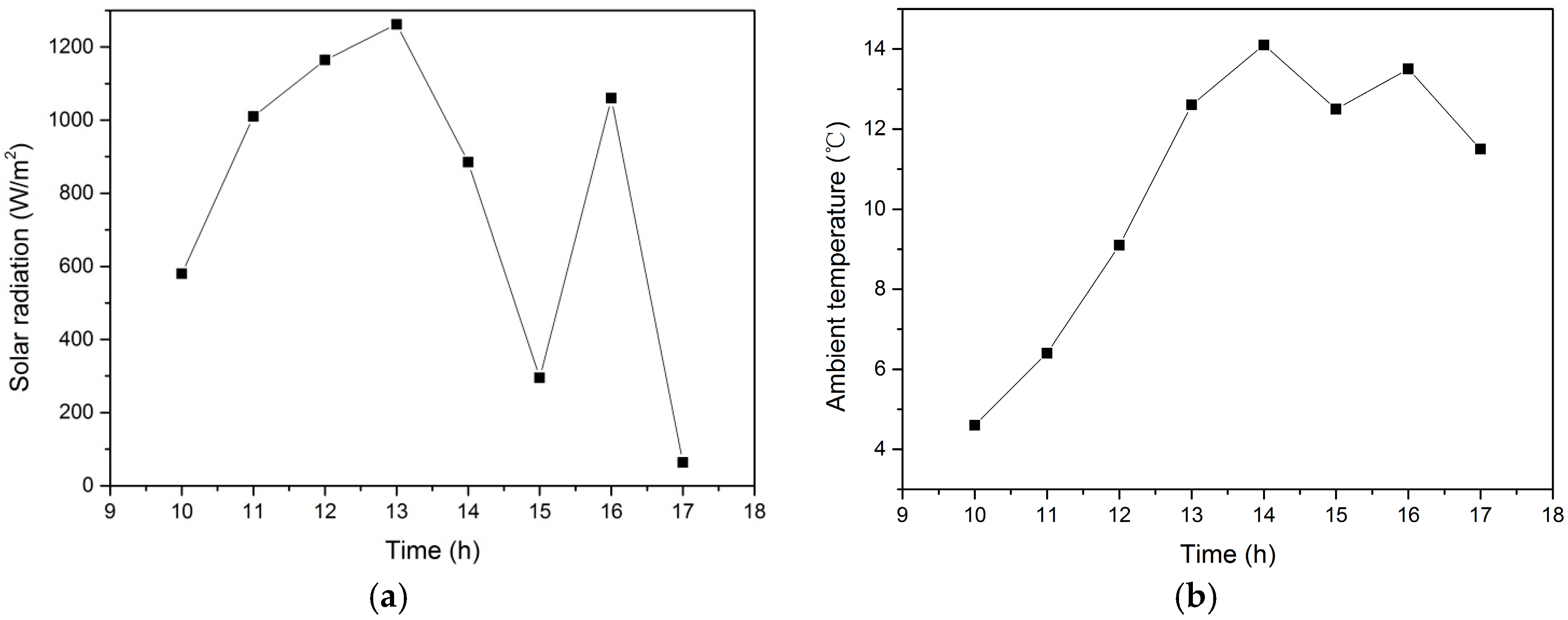
The initial temperature distribution of the water region was uniform at 45 °C. The water mass flow rates of 1-1# inlet, 1-2# inlet and 2# inlet were 5.0, 2.5 and 16.0 kg/s, respectively. The water temperatures of the 1-1#, 1-2# and 2# inlets are shown in Figure 4. Figure 5 shows the solar radiation and ambient temperature.
Due to a smaller solar collection area and a larger water mass flow rate, the water temperature of 1-1# inlet was lower than that of 1-2# inlet. The water temperature variations of the 1-1# and 1-2# inlets had similar tendencies as the solar radiation and ambient temperature. Before 14:00, more solar heat was collected with the increase of solar radiation and ambient temperature and both 1-1# and 1-2# inlet temperatures showed an overall increase tendency. From 14:00 to 15:00, heat gain of solar collectors decreased with less solar radiation and ambient temperature, where the temperatures of 1-1# and 1-2# inlets showed a decrease tendency. Similar temperature variation tendencies of 1-1# and 1-2# inlets can be found during 15:00 to 17:00.
3. Numerical Approach
3.1. Model Setting
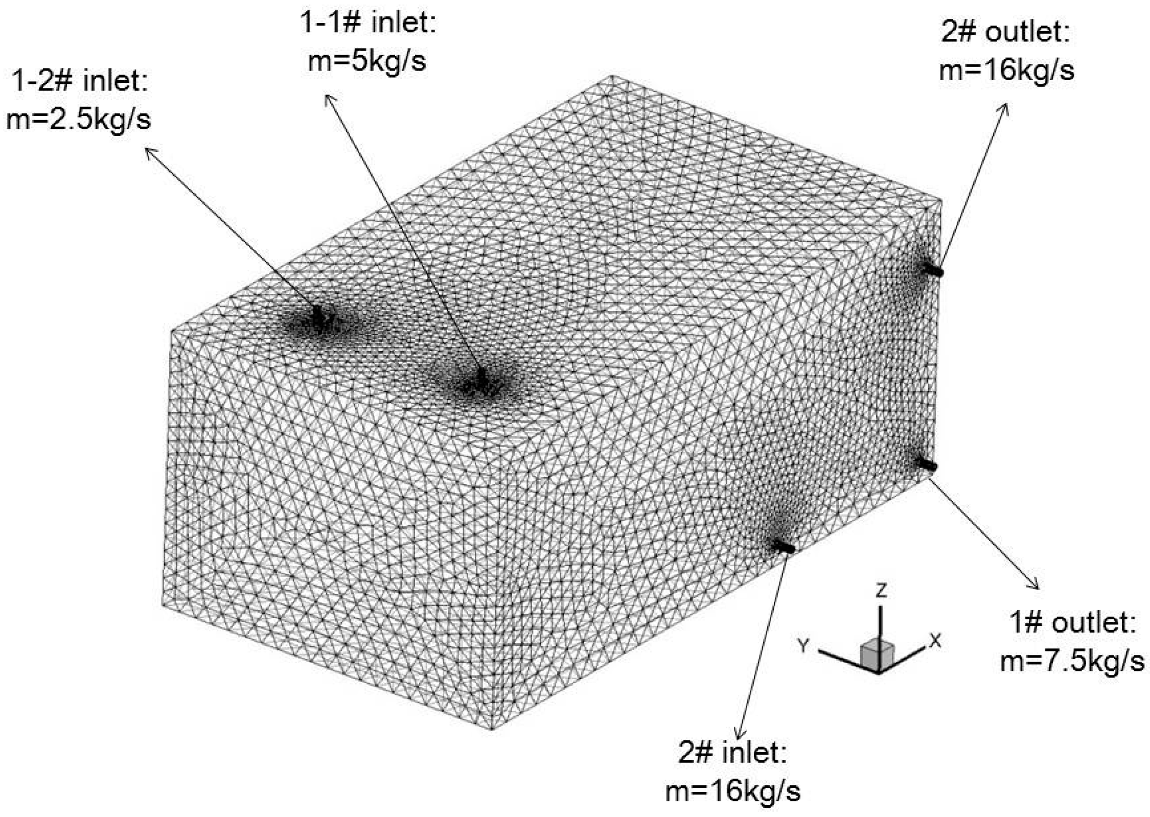
Assuming no heat losses from the storage tank to the ambient the dynamic heat transfer process of water inside the tank under the simultaneous charging and discharging operation mode was numerically studied using a computational fluid dynamics (CFD) approach, taking into account the natural convection effect by Boussinesq approximation. Fluent 15.0 was used to mesh the heat storage tank and an unstructured mesh using tetrahedral cells was applied. All governing equations together with the boundary conditions over the whole domain were solved by the commercial CFD code Fluent 15.0. The Semi-Implicit Method for Pressure-Linked Equations (SIMPLE) algorithm was used for the pressure velocity coupling; the Pressure Staggering Option (PRESTO) scheme was applied for the pressure interpolation. A second-order upwind scheme was adopted for the discretization of the momentum equation, energy equation, turbulent kinetic energy equation and dissipation rate equation (standard model). The influence of the grid number and time step on the numerical result was checked, and different grid numbers and time steps were tested. Three different meshes of 32,971, 82,065 and 160,283 grids and three time steps of 0.25, 0.5 and 1 s were examined. The model with 82,065 grids and time steps of 0.25 and 0.5 s produced very similar variations in the average water temperature inside the tank. The results did not show any significant change as the number of grids increased to 160,283. In order to balance the numerical accuracy and computational resources and time, 82,065 grids and 0.5 s were chosen in the present numerical calculation. Solution convergence target was set as 10−7 for the energy equation and 10−3 for other variables. To compare the numerical water temperatures inside the tank with the experimental ones under the same boundary conditions, the initial water temperature and dynamic inlet water temperatures as well as the inlet/outlet water mass flow rates of the tank numerical model were taken from the test data. The initial water temperature was set as 45 °C. The dynamic inlet water temperatures (shown in Figure 4) were inputted and interpreted to the numerical model of the tank by User Defined Function (UDF). The water mass flow rates of 1-1# inlet,1-2# inlet and 2# inlet were set as 5, 2.5 and 16 kg/s, respectively. The water mass flow rates of 1# outlet and 2# outlet were set as 7.5 and 16 kg/s, respectively. The computational region of the heat storage tank is shown in Figure 6.
3.2. Validation
The numeric model of the tank was validated by comparing the predicted temperatures with the measured ones from three thermocouples labelled T1, T2 and T3, located at three different depths (at a distance of 2.4, 2 and 1 m from the bottom, respectively) inside the tank (Figure 7). It can be observed that the numerical temperatures agreed well with the experimental temperatures with a relative error of less than 3% for each depth. The insignificant temperature stratification inside the tank was mainly attributed to three factors: thermal mixing at the inlet, natural convection flow and the relatively low height-diameter ratio of the tank. The tank acts as a heat collection and heat consumption buffer. As more heat is collected and less heat consumed due to the increase of the solar radiation and ambient temperature, the increase of the solar radiation and ambient temperature will boost the mean water temperature of the tank. Before 14:00, more solar heat was collected and less heat consumed with the increase of solar radiation and ambient temperature, the mean water temperature showed an overall increasing tendency. Similar temperature variation tendencies of the mean water temperature can be found from 14:00 to 17:00. With some time spent on mixing the hot water in the tank, a several-minute delay could be found between the variation of mean water temperature and that of the solar radiation and ambient temperature.
The test error of the thermocouples is ±0.5 °C and the uncertainty of the measured water temperatures is as follows:
3.3. Numeric Analysis
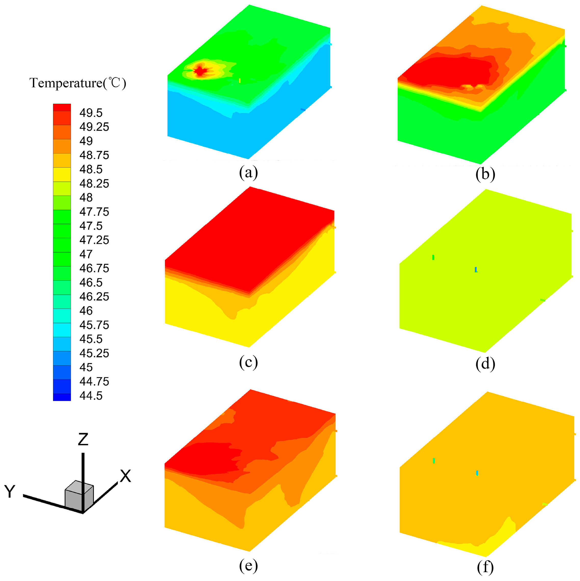
Figure 8 and Figure 9 show the temperature distribution of the tank over time. From 10:30 to 14:00, the water inlet temperatures from the solar collectors increased with increase of the solar radiation and ambient temperature, and a stratified thermocline appeared due to the natural convection of the heat and cold layers. From 14:00 to 15:00, the water inlet temperatures decreased with decrease of the solar radiation and ambient temperature. Combined with the mixing effect at 1-1#/1-2# inlets and the natural convection flow inside the tank, the stratified thermocline gradually degraded and nearly disappeared by 15:00. The stratified thermocline appeared again with higher water inlet temperatures in the following hour (from 15:00 to 16:00). The degradation of stratified thermocline appeared again with decreases of the solar radiation and ambient temperature from 16:00 to 17:00. The stratification inside the tank was not apparent due to the mixing effect at the inlets and the natural convection flow inside the tank as well as the relatively low height-diameter ratio of the tank.
This numerical approach offers a calculation method of the tank temperature distribution under the simultaneous charging and discharging operation mode. By this method, the correlation between the output water temperatures of the tank and the input water temperatures of the tank is set up. For the system optimization, the coupling temperature relation is a key point. Therefore, this method can be used to optimize the component size and operation parameters of the solar heating system in the future study.
4. Analysis of the System Performance
In addition to the numeric calculation method of the tank temperature distribution, the system COP and the heating effect were also investigated in this study to illustrate the thermal performance of the solar heating system under the simultaneous charging and discharging operation mode in Lhasa.
4.1. System COP
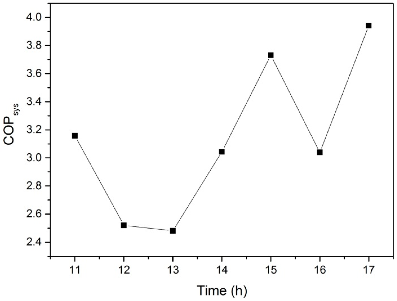
The system COP is defined as the ratio between the heat supplied by the plate heat exchanger to the FCU and the energy consumption of the water pumps as well as FCUs. It represents the energy utilization efficiency of the solar heating system. According to the test, the power of the solar collection pumps, the intermediate circuit pumps and the hot water pumps were 6.6, 5.9 and 4.1 kW, respectively. However, the energy consumption of the FCU was variable because its switch is controlled by people in the room. To solve this problem, the coincidence factor and the overall nominal power were used to estimate the energy consumption of the FCU. In this study, the nominal power of all FCUs was about 2.5 kW, the coincidence factor was estimated 0.6. The transient system COP was calculated and shown in Figure 10. It can be seen that the system COP is higher than 3.0 mostly the time and the minimum value is higher than 2.5. Meanwhile, the system COP of the electric heating system which is still widely used in Lhasa is 1.0. The system COP of the gas boiler heating system is about 3.0 in low-altitude area. Through the comparison, the system COP is nearly equal to that of the gas-boiler heating system and much higher than that of the electrical heating system. Therefore, the simulative charging and discharging operation mode for the solar heating system in Lhasa can effectively enhance the system energy utilization efficiency.
4.2. Heating Effect
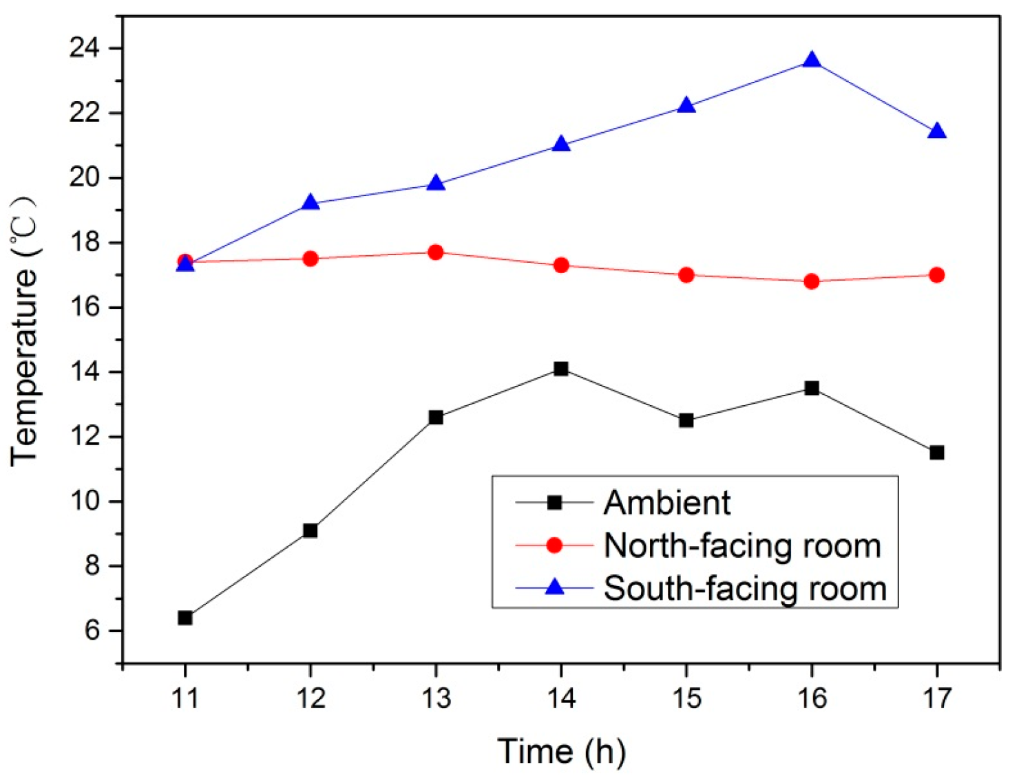
To investigate the system heating effect, a north-facing room of the No.2 building and a south-facing room of the No.1 building were adopted representing the worst and best sunshine conditions, respectively. Both room temperatures over time are shown in Figure 11, compared with the ambient temperature. It can be observed that the north-facing room and the south-facing room both satisfy the room temperature requirement which is higher than 16 °C. For the south-facing room, the mean temperature is about 17 °C; for the south-facing room, the mean temperature is over 20 °C and the maximum temperature nearly gets to 24 °C. It indicates that the solar heating system under the simulative charging and discharging operation mode shows good heating effect.
4.3. Optimization Directions
Although the solar heating system under the simulative charging and discharging operation mode can meet the room temperature requirement with a relatively high system COP, there is still some space to improve for the following study:
- Resetting the mass flow rates of the solar collecting cycles. In this study, the mass flow rates of the 1-1# and 1-2# solar collecting cycles are 5.0 and 2.5 kg/s, respectively. From Figure 4, the 1-1# inlet temperature is much lower than 1-2# inlet temperature, with a mean temperature difference of 5 °C. At some time with high solar radiation (13:00), this difference even exceeds 10 °C. This large temperature difference results in the mixture of the hot water and cold water which addresses the thermal exergy loss and the reduction of the solar energy utilization efficiency. This is mainly attributed to the unreasonable mass flow rate setting of the solar collecting cycles. Therefore, the 1-1# solar collecting cycle should set a lower mass flow rate. On the one hand, the temperature difference between the 1-1# inlet and 1-2# inlet can be balanced. On the other hand, the energy consumption of the solar collecting pumps can be reduced and the system COP can be improved.
- Setting a reasonable control stagey for the FCU. In the initial period and the last period of the heating season in Lhasa, the heat load is relatively low. Due to the different sunshine conditions, the south-facing rooms and the north-facing rooms show different thermal environments when the FCU is switched on. As shown in Figure 11, the temperature of the south-facing room exceeds 20 °C most of the time and even reaches to 24 °C in the afternoon. It is much higher than that of the north-facing room. Therefore, the electric two-way valve can be used for the FCU to realize the variable water volume operation, which can adjust the indoor temperature, especially for the south-facing room.
5. Conclusions
In this study, the investigation for an accurate solar heating system in Lhasa (Tibet) was addressed. Based on the solar heating system, a numerical calculation method of the tank temperature distribution under the simultaneous charging and discharging operation mode was proposed and validated by experiments. The system COP and heating effect were tested. Several recommendations for the system optimization are made for future study. The following conclusions can be drawn:
- The numerical calculation method of the tank temperature distribution under the simultaneous charging and discharging operation mode offers a correlation between the output water temperatures of the tank and the input water temperatures of the tank, which can be used to optimize the solar heating system in future study.
- The solar heating system under the simultaneous charging and discharging operation mode has a relatively high system COP as well as good heating effect.
- During the initial and last period of the heating season in Lhasa, the simultaneous charging and discharging operation mode of the solar water heating system is a good attempt to maintain the indoor comfort during the daytime and worth further in-depth research in the future.
Acknowledgments
This research is financially supported by the Science and Technology Ministry of China (Project No. 2016YFC0700406) and the 111 Project (No. B13041).
Author Contributions
Yong Wang and Xun Yang conceived and designed the experiments; Xun Yang and Teng Xiong performed the experiments and analyzed the data; Xun Yang wrote the paper.
Conflicts of Interest
The authors declare no conflict of interest.
Nomenclature
| flow rate of water pump (m3/h) | heat transfer rate of plate heat exchanger (kW) | ||
| head of water pump (m) | length of solar collector (m) | ||
| power of water pump (kW) | width of solar collector (m) | ||
| length of heat storage tank (m) | thickness of solar collector (m) | ||
| width of heat storage tank (m) | efficiency factor of solar collector | ||
| height of heat storage tank (m) | transmittance of solar collector | ||
| air flow rate of FCU (m3/h) | absorptivity of solar collector | ||
| heat transfer rate of FCU (W) | heat loss coefficient of solar collector (W/(m2·°C)) | ||
| power of FCU (W) | uncertainty | ||
| water mass flow rate (kg/s) |
References
- Jiang, Y.; Rong, X.; Feng, Y.; Pan, Y.; Fu, X. Discussion for urban heating mode for Lhasa. HV AC 2013, 43, 1–7. [Google Scholar]
- Pan, Y. Test and analysis of solar hot water heating system in Lhasa railway station. HV AC 2009, 39, 121–127. [Google Scholar]
- Rong, X. Suitability analysis for Lhasa heating techniques. HV AC 2013, 43, 23–30. [Google Scholar]
- Calise, F.; Figaj, R.D.; Vanoli, L. Experimental and numerical analyses of a flat plate photovoltaic/thermal solar collector. Energies 2017, 10, 491. [Google Scholar] [CrossRef]
- Calise, F.; Accadia, M.D.; Piacentino, A.; Vicidomini, M. Thermo-economic optimization of a renewable polygeneration system serving a small isolated community. Energies 2015, 8, 995–1024. [Google Scholar] [CrossRef]
- Calise, F.; Capuano, D.; Vanoli, L. Dynamic simulation and exergo-economic optimization of a hybrid solar–geothermal cogeneration plant. Energies 2015, 8, 2606–2646. [Google Scholar] [CrossRef]
- Calise, F.; Libertini, L.; Vicidomini, M. Exergetic analysis of a novel solar cooling system for combined cycle power plants. Energies 2016, 18, 356. [Google Scholar] [CrossRef]
- Buker, M.S.; Mempouo, B.; Riffat, S.B. Performance evaluation and techno-economic analysis of a novel building integrated PV/T roof collector: An experimental validation. Energy Build. 2014, 76, 164–175. [Google Scholar] [CrossRef]
- Buker, M.S.; Riffat, S.B. Build-up and performance test of a novel solar thermal roof for heat pump operation. Int. J. Ambient. Energy 2017, 38, 365–379. [Google Scholar] [CrossRef]
- Buker, M.S.; Riffat, S.B. Building integrated solar thermal collectors—A review. Renew. Sustain. Energy Rev. 2015, 51, 327–346. [Google Scholar] [CrossRef]
- Bernardo, L.R.; Davidssonand, H.; Andersson, E. Retrofitted solar domestic hot water systems for Swedish single-family houses—Evaluation of a prototype and life-cycle cost analysis. Energies 2016, 9, 953. [Google Scholar] [CrossRef]
- Wilson, M.B.; Luck, R.; Mago, P.J. A first-order study of reduced energy consumption via increased thermal capacitance with thermal storage management in a micro-building. Energies 2015, 8, 12266–12282. [Google Scholar] [CrossRef]
- Bernardo, L.R. Retrofitting conventional electric domestic hot water heaters to solar water heating systems in single-family houses—Model validation and optimization. Energies 2013, 6, 953–972. [Google Scholar] [CrossRef]
- Moretti, E.; Bonamente, E.; Buratti, C.; Cotana, F. Development of innovative heating and cooling systems using renewable energy sources for non-residential buildings. Energies 2013, 6, 5114–5129. [Google Scholar] [CrossRef]
- Bernardo, L.R.; Davidsson, H.; Karlsson, B. Retrofitting domestic hot water heaters for solar water heating systems in single-family houses in a cold climate: A theoretical analysis. Energies 2012, 5, 4110–4131. [Google Scholar] [CrossRef]
- Ko, M.J. Multi-objective optimization design for indirect forced-circulation solar water heating system using NSGA-II. Energies 2015, 8, 13137–13161. [Google Scholar] [CrossRef]
- Ko, M.J. A novel design method for optimizing an indirect forced circulation solar water heating system based on life cycle cost using a genetic algorithm. Energies 2015, 8, 11592–11617. [Google Scholar] [CrossRef]
- Ko, M.J. Analysis and optimization design of a solar water heating system based on life cycle cost using a genetic algorithm. Energies 2015, 8, 11380–11403. [Google Scholar] [CrossRef]
- Lin, W.-M.; Chang, K.-C.; Liu, Y.-M.; Chung, K.-M. Field surveys of non-residential solar water heating systems in Taiwan. Energies 2012, 5, 258–269. [Google Scholar] [CrossRef]
- Hugo, A.; Zmeureanu, R. Residential solar-based seasonal thermal storage systems in cold climates: Building envelope and thermal storage. Energies 2012, 5, 3792–3985. [Google Scholar] [CrossRef]
- Jamar, A.; Majid, Z.A.A.; Azmi, W.H.; Norhafana, M.; Razak, A.A. A review of water heating system for solar energy applications. Int. J. Heat Mass Transf. 2016, 76, 178–187. [Google Scholar] [CrossRef]
- Gautama, A.; Chamolib, S.; Kumara, A.; Singhc, S. A review on technical improvements, economic feasibility and world scenario of solar water heating system. Renew. Sustain. Energy Rev. 2017, 68, 541–562. [Google Scholar] [CrossRef]
- Tian, Y.; Zhao, C.Y. A review of solar collectors and thermal energy storage in solar thermal applications. Appl. Energy 2013, 104, 538–553. [Google Scholar] [CrossRef]
- Baeten, B.; Confrey, T.; Pecceu, S.; Rogiers, F.; Helsen, L. A validated model for mixing and buoyancy in stratified hot water storage tanks for use in building energy simulations. Appl. Energy 2016, 172, 217–229. [Google Scholar] [CrossRef]
- Spur, R.; Fiala, D.; Nevrala, D.; Probert, D. Performances of modern domestic hot-water stores. Appl. Energy 2006, 83, 893–910. [Google Scholar] [CrossRef]
- De Coninck, R.; Baetens, R.; Saelens, D.; Woyte, A.; Helsen, L. Rule-based demand-side management of domestic hot water production with heat pumps in zero energy neighborhoods. J. Build. Perform. Simul. 2014, 7, 271–288. [Google Scholar] [CrossRef]
- Farooq, A.A.; Afram, A.; Schulz, N.; Janabi-Sharifi, F. Grey-box modeling of a low pressure electric boiler for domestic hot water system. Appl. Therm. Eng. 2015, 84, 257–267. [Google Scholar] [CrossRef]
- Mohan, G.; Kumar, U.; Pokhrel, M.K.; Martin, A. A novel solar thermal polygeneration system for sustainable production of cooling, clean water and domestic hot water in United Arab Emirates: Dynamic simulation and economic evaluation. Appl. Energy 2016, 167, 173–188. [Google Scholar] [CrossRef]
- Zhang, Y.; Wang, X.; Zhuo, S.; Zhang, Y. Pre-feasibility of building cooling heating and power system with thermal energy storage considering energy supply-demand mismatch. Appl. Energy 2016, 167, 125–134. [Google Scholar] [CrossRef]
- Granado, P.C.D.; Pang, Z.; Wallace, S.W. Synergy of smart grids and hybrid distributed generation on the value of energy storage. Appl. Energy 2016, 170, 476–488. [Google Scholar] [CrossRef]
- Han, Y.M.; Wang, R.Z.; Dai, Y.J. Thermal stratification within the water tank. Renew. Sustain. Energy. Rev. 2009, 13, 1014–1026. [Google Scholar] [CrossRef]
- Van Berkel, J.; Rindt, C.C.M.; van Steenhoven, A.A. Thermocline dynamics in a thermally stratified store. Int. J. Heat Mass Transf. 2002, 45, 343–356. [Google Scholar] [CrossRef]
- Shin, M.-S.; Kim, H.-S.; Jang, D.-S.; Lee, S.-N.; Lee, Y.-S.; Yoon, H.-G. Numerical and experimental study on the design of a stratified thermal storage system. Appl. Therm. Eng. 2004, 24, 17–27. [Google Scholar] [CrossRef]
- Ievers, S.; Lin, W. Numerical simulation of three-dimensional flow dynamics in a hot water storage tank. Appl. Energy 2009, 86, 2604–2614. [Google Scholar] [CrossRef]
- Yaïci, W.; Ghorab, M.; Entchev, E.; Hayden, S. Three-dimensional unsteady CFD simulations of a thermal storage tank performance for optimum design. Appl. Therm. Eng. 2013, 60, 152–163. [Google Scholar] [CrossRef]
- Erdemir, D.; Altuntop, N. Improved thermal stratification with obstacles placed inside the vertical mantled hot water tanks. Appl. Therm. Eng. 2016, 100, 20–29. [Google Scholar] [CrossRef]
- Soo Too, Y.C.; Morrison, G.L.; Behnia, M. Performance of solar water heaters with narrow mantle heat exchangers. Sol. Energy 2009, 83, 350–362. [Google Scholar] [CrossRef]
- Arslan, M.; Igci, A.A. Thermal performance of a vertical solar hot water storagetank with a mantle heat exchanger depending on the discharging operation parameters. Sol. Energy 2015, 116, 184–204. [Google Scholar] [CrossRef]
- Dehghan, A.A.; Barzegar, A. Thermal performance behavior of a domestic hot water solar storage tank during consumption operation. Energy Convers. Manag. 2011, 52, 468–476. [Google Scholar] [CrossRef]
- Pan, Y. Some opinions on solar energy hot water heating for buildings in Qinghai-Tibetan plateau. HV AC 2013, 43, 15–22. [Google Scholar]
Figure 1.
Schematic diagram of the solar heating system.

Figure 2.
Solar collection zones: (a) 1-1# zone; (b) 1-2# zone.

Figure 3.
Solar water heat storage tank.

Figure 4.
Water temperatures of the tank inlets.

Figure 5.
(a) Solar radiation and (b) ambient temperature.

Figure 6.
Computational region of the heat storage tank.

Figure 7.
Comparisons of numerical and experimental results.

Figure 8.
Temperature distribution of the heat storage tank (profile): (a) 12:00; (b) 13:00; (c) 14:00; (d) 15:00; (e) 16:00; (f) 17:00.
Figure 8.
Temperature distribution of the heat storage tank (profile): (a) 12:00; (b) 13:00; (c) 14:00; (d) 15:00; (e) 16:00; (f) 17:00.

Figure 9.
Temperature distribution of the heat storage tank (Y = 0): (a) 12:00; (b) 13:00; (c) 14:00; (d) 15:00; (e) 16:00; (f) 17:00.
Figure 9.
Temperature distribution of the heat storage tank (Y = 0): (a) 12:00; (b) 13:00; (c) 14:00; (d) 15:00; (e) 16:00; (f) 17:00.

Figure 10.
System COP over time.

Figure 11.
Variations of the room temperatures and the ambient temperature.


Table 1.
Technical parameters of the main units.
| Name | Technical Parameters |
|---|---|
| Hot water pump | WILO65-28/2: Lpump = 49 m3/h, Hpump = 28 m, Npump = 4 kW |
| Intermediate circuit pump | WILO50-21/2: Lpump = 40 m3/h, Hpump = 21 m, Npump = 3 kW |
| Solar collection pump | WILO65-45/2: Lpump = 17 m3/h, Hpump = 45 m, Npump = 5 kW |
| Plate heat exchanger | QHE = 300 kW |
| Solar water storage tank | Ltank = 7 m, Wtank = 4 m, Htank = 3 m |
| FCU | MFMW200C: LFCU = 340 m3/h, QFCU = 3565 W, NFCU = 35 W |
| Solar collector | NS-PGT2.0: Lsc = 2 m, Wsc = 1 m, δsc = 0.08 m, FR = 0.9, τ = 0.9, α = 0.92, UL = 5 W/(m2·°C) |
© 2017 by the authors. Licensee MDPI, Basel, Switzerland. This article is an open access article distributed under the terms and conditions of the Creative Commons Attribution (CC BY) license (http://creativecommons.org/licenses/by/4.0/).
Share and Cite
MDPI and ACS Style
Yang, X.; Wang, Y.; Xiong, T. Numerical and Experimental Study on a Solar Water Heating System in Lhasa. Energies 2017, 10, 963. https://doi.org/10.3390/en10070963
AMA Style
Yang X, Wang Y, Xiong T. Numerical and Experimental Study on a Solar Water Heating System in Lhasa. Energies. 2017; 10(7):963. https://doi.org/10.3390/en10070963
Chicago/Turabian StyleYang, Xun, Yong Wang, and Teng Xiong. 2017. "Numerical and Experimental Study on a Solar Water Heating System in Lhasa" Energies 10, no. 7: 963. https://doi.org/10.3390/en10070963
Note that from the first issue of 2016, this journal uses article numbers instead of page numbers. See further details here.