The Concept of Segmented Wind Turbine Blades: A Review


1
Department of Materials, Textiles and Chemical Engineering, Ghent University, Tech Lane Ghent Science Park—Campus A, Technologiepark-Zwijnaarde 903, 9052 Zwijnaarde, Belgium
2
Department of Flow, Heat and Combustion Mechanics, Ghent University, Sint-Pietersnieuwstraat 41, 9000 Ghent, Belgium
*
Author to whom correspondence should be addressed.
Energies 2017, 10(8), 1112; https://doi.org/10.3390/en10081112
Submission received: 23 June 2017
/
Revised: 17 July 2017
/
Accepted: 18 July 2017
/
Published: 31 July 2017
Abstract
:There is a trend to increase the length of wind turbine blades in an effort to reduce the cost of energy (COE). This causes manufacturing and transportation issues, which have given rise to the concept of segmented wind turbine blades. In this concept, multiple segments can be transported separately. While this idea is not new, it has recently gained renewed interest. In this review paper, the concept of wind turbine blade segmentation and related literature is discussed. The motivation for dividing blades into segments is explained, and the cost of energy is considered to obtain requirements for such blades. An overview of possible implementations is provided, considering the split location and orientation, as well as the type of joint to be used. Many implementations draw from experience with similar joints such as the joint at the blade root, hub and root extenders and joints used in rotor tips and glider wings. Adhesive bonds are expected to provide structural and economic efficiency, but in-field assembly poses a big issue. Prototype segmented blades using T-bolt joints, studs and spar bridge concepts have proven successful, as well as aerodynamically-shaped root and hub extenders.
1. Introduction
Over the past few decades, wind turbines have been developing rapidly. Most notably, the size of the rotor diameter and the corresponding power output have been increasing steadily to rotor diameters of up to 180 m, with rated powers as high as 9.5 MW [1,2,3]. This up-scaling trend is still ongoing, especially offshore, and is motivated by an expected reduced cost of energy (COE) for larger rotors as a result of increased economies of scale [4,5,6,7]. However, this up-scaling leads to issues that can cause a steep increase in costs related to the production and handling of blades, to the extent that further up-scaling may no longer be beneficial. As a consequence, optimal rotor sizes exist for on- and off-shore turbines, which can increase as a result of technical improvements [2]. Furthermore, methods to reduce the loads on the rotor have proven successful for reducing the COE. The increase in size of the blades has led to interest in the concept of so-called “segmented” blades. Instead of the conventional single piece blades, these are manufactured as a number of segments, which can be transported individually and assembled at the site of the turbine. While the “segmented”, “split” or “modular” blade concept is not new, it has recently gained increased interest. This paper intends to provide the reader with an overview of the concept. Design options include span-wise or chord-wise segmentation, the purpose and location of the division, as well as the use of a static joint or a variable mechanism. The available options are discussed along with their advantages and limitations. Furthermore, the feasibility of different methods is discussed.
2. Wind Turbine Blade Manufacturing
While initially, aerospace methodologies were used, most modern wind turbine blades are manufactured from composite materials using methods derived from ship building [8,9]. Large clamshell molds are used to manufacture separate pressure sides (PS) and suction sides (SS) and a number of shear webs. This is done using processes such as the lamination of pre-impregnated material, bladder molding, wet-layup or vacuum assisted resin transfer molding (VARTM) [10,11,12]. The material is currently placed manually, but can be automated [13,14]. Most frequently, the separate components are joined together using thick adhesive bonds [15]. As the blade size increases, this leads to issues. Firstly, tolerances increase resulting in thickness variations of the adhesive bonds, which add weight and cause stress concentrations [16]. Secondly, heating and temperature control become more difficult, while very thick laminates give exothermic reactions, which can damage the blade [17]. Thirdly, defects become more severe and prevalent in larger volumes resulting in a lower strength than assumed from coupon data [18]. These defects lower the load-carrying capacity of the blade and may require scrapping the part, which is more expensive for a larger blade [19,20]. Lastly, modern blades are often designed with a pre-curved shape, to ensure sufficient tower clearance under extreme load without using a very stiff design [21].
Modifications have been suggested to counter the issues with manufacturing large blades. Typically, these allow production in separate components, allowing better quality of the individual pieces. Frequently, a separately cured spar structure is used [18]. Furthermore, Hayden [22] suggested to build the spar cap out of thin pultruded planks glued on top of each other to avoid thick laminates. Hayden [17] suggested producing the blade root in multiple segments for better temperature control. Kontis [23] suggested producing large parts of the blades separately and joining them together using adhesive bonds before transport. This approach has the advantage of manufacturing segments and avoids the difficulty of on-site assembly. Additionally, to improve the quality of the adhesive bonds at the shear webs, Sorensen [24] advocated producing the internal spar of a blade in two pieces, of which the height can be adjusted in order to obtain the desired bond thickness.
3. Transportation of Wind Turbine Blades
In general, wind turbine blades are manufactured at a production facility and subsequently transported to the installation site [25]. Due to legislation differing between countries, the total number of transports and various other factors, transportation costs are highly route dependent. Every haul requires investigation of the optimal route and transportation method [26]. While wind turbine blades are frequently transported by road, typically, lengths of over 45 m need to be transported as oversized and overweight (OSOW) load requiring specialized trucks with rear steering escorted by service cars [27]. The route has to be analyzed to ensure blade transport vehicles can be accommodated [27]. Furthermore, modifications to the road may be required, and local regulations may restrict road transportation to nighttime, specific weather conditions and may impose special licenses [28,29]. Licenses with a limited validity period introduce lead-times and additional costs in the case of a delay [30]. Wind turbine blades can also be transported by rail. While blade lengths are not limited to the size of a single rail car, trains have to go slower when part of the blade is hanging over board [31]. Further, blades are also transported over waterways and seas. However, to prevent twisting of the ship from damaging the blades, expensive fixtures, custom to every blade type, have to be used [29]. As a last resort, blades can also be transported by air lifters. Because helicopters are expensive and risky, blimp like air lifting devices are under development [26,32]. Increased difficulty of transporting larger blades results in a non-linear increase in costs. Beyond certain breakpoints there is a sudden steep increase [26]. On the road, transportation costs rise sharply for blade lengths over 46 m and can be prohibitive for blades longer than 61 m [18]. Furthermore, there are actual limitations to the dimensions of components that can be transported for each method [33]. These apply to the bounding box surrounding the blade. As can be seen in Figure 1, the height and width of the box is determined by the blade’s maximum chord length and the blade root diameter, as well as the amount of pre-bending and pre-curving. An overview of the maximum allowed dimensions and weights is given in Table 1.
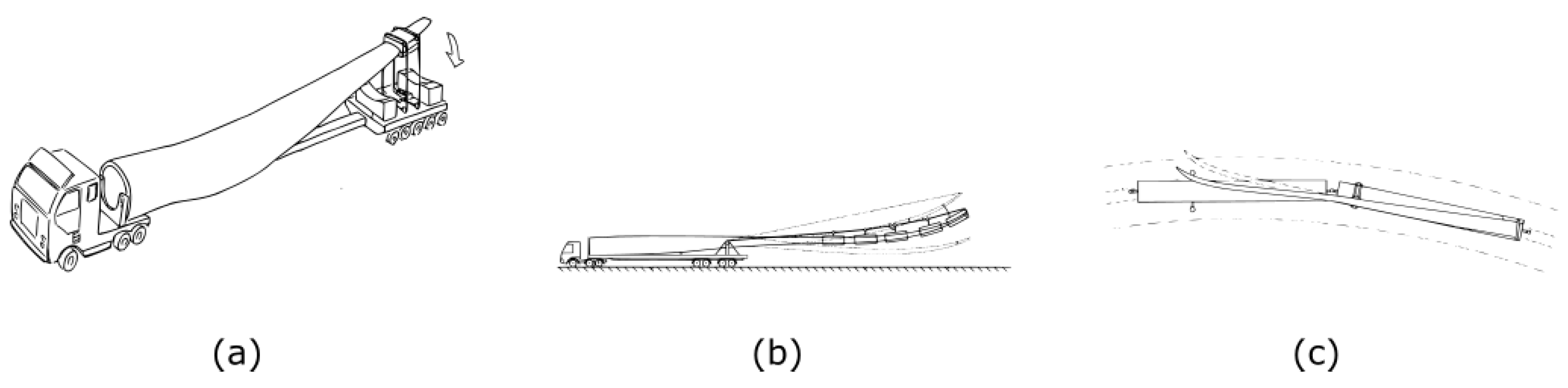
Various improvements have been made to the conventional transportation methods. One possible approach is to make the position in which the blade is carried variable. Jensen [34] suggested a system where the blade is suspended at both ends, which can each be lifted. This allows the blade to be lifted over small obstacles. Similarly, Wobben [35] suggested to rotate the blade to pass under obstacles such as bridges. These systems can be seen in Figure 2. Likewise, Kawada [36] proposed connecting only the blade root to a truck with a system that enables tilting the tip upwards. This allows larger blades to get past a narrow corner. Furthermore, Nies [37] suggested tilting the blade and reducing the length of the carrying vehicle. Additionally, Pedersen [38] improved upon these tilting concepts, allowing the blade tip to be in front of the truck while using a lighter vehicle. To allow larger blades to be transported by rail, Landrum [39] proposed using two coupled rail cars and using a sliding support. Another approach is to deform the blade to alter its dimensions. Modern wind turbine blades are often pre-curved and swept. For larger blades, however, the amount of pre-curving is less than desirable, due to the difficulty of transport [40]. This issue could be reduced by applying a load to “straighten” out the blades while they are transported [40]. In addition, to improve blade transportation by rail, Schibsbye [31] advocated using bumpers to bend the more flexible outboard portion of the blades during turns so that there would be no overhang. An overview of these methods can be seen in Figure 3. Further, the transportation of blades over water is less restricted. Grabau [29] proposed to take advantage of the similarity between blades and composite boats. When all gaps are sealed, the blades can float in the water and towed behind a ship. Alternatively, Berry [41] investigated producing blades in a small on-site factory using material kits prepared at the main factory. However, there were difficulties with handling the blades at the temporary facility.
4. The Cost of Energy: Requirements for Segmented Blades
4.1. Cost of Energy Components
The overall aim of the wind energy industry is to provide energy at the lowest possible cost. This cost is affected by segmenting. The cost of energy ( ) can be modeled as suggested in [44], as can be seen in (1). The depends on the fixed charge rate (), the initial capital cost (), the net annual energy production of the turbine (), the land lease cost (), operations and maintenance () cost and the levelized replacement cost ().
4.2. The Initial Capital Cost
The depends on manufacturing transportation and installation cost of the turbine. Manufacturing costs increase because of the additional material, labor and production steps required for producing the joint and reinforcing the inboard part of the blade [45]. On the other hand, a cost reduction is possible due to economic benefits. Production facilities can be smaller [45,46,47], and components can be standardized. For example, a single root segment can be combined with different tip segments to obtain blades for different wind conditions [48,49]. Additionally, using different materials at different locations along the span is economically interesting, but requires a difficult transition. This can be simplified by segmenting [50,51]. Furthermore, segmentation simplifies quality assurance [50]. Blade segmentation can decrease transportation costs [45]. Moreover, many sites that are suited for wind turbines are located in complex terrain with poor infrastructure. Their development may become cost effective with segmented blades [52,53]. Installation costs increase because of additional assembly steps required to make the final blade. In this respect, speed and simplicity of assembly are important.
4.3. Operations and Maintenance Cost
The cost for operations and maintenance () increases because of additional inspections or maintenance. It may be required to verify the pre-stress of bolts or the protection against water ingress [54]. Minimal additional maintenance and good access and inspectability to the joint are required to limit this cost increase. Therefore, sensors can be included to monitor the joint [55].
4.4. Levelized Replacement Cost
4.5. Net Annual Energy Production
Further, the annual energy production () has a very strong influence on the since it has to offset all of the costs including those not related to the rotor. The performance of the rotor will decrease by alterations to its outside shape. Therefore, joints should use holes that can be covered or blind holes from the inside of the blade [51]. Furthermore, a lower rotor inertia makes it easier for the control system to keep the ratio of the rotational speed of the rotor to the wind speed optimal under fluctuating wind conditions, thereby resulting in a higher [58]. The additional inertia resulting from the joint may therefore reduce the . Additionally, the will be decreased if a local stiffened portion is included [59].
4.6. General Considerations for Segmented Blades
In order to minimize the resulting from a segmented blade, the different cost components have the following considerations based on Dutton and Birkemeyer [45,60].
- Initial capital costs
- –
- manufacturing costs
- –
- tolerance requirements
- –
- production complexity and accuracy
- –
- ability to use with conventional production methods
- –
- quality control
- –
- positioning accuracy and speed of assembly
- Annual energy production
- –
- reliability
- –
- aerodynamics
- –
- weight of the joint
- Annual operating expenses
- –
- requiring minimal inspection
- –
- easy to repair during service
- –
- possibility of disassembly for replacing segments
4.7. Cost Effectiveness of Blade Segmentation
Segmenting blades is useful if this results in a reduced . For example, Dutton [45] reported an expected increase in blade cost of approximately 19% for a 60-m blade, while the transportation costs decreased only about 5% of the total price of the blade, thus overall resulting in an elevated . However, from Dutton [45], it is clear that the relative added cost of segmenting a blade decreases with the size of the blades. Further, at a turbine level, the optimum scale is determined by the ratio between capital costs and other costs [2]. Because the fixed costs are significantly higher for offshore turbines than for their onshore counterparts, the optimum size for offshore turbines is larger than onshore [2]. Additionally, for land-based turbines, transportation costs may be extremely high for certain sites that do allow for a high . Therefore, segmentation is most likely to be cost effective for either very large, typically offshore turbines or on-shore turbines that are installed on sites that allow a high yield, but are otherwise difficult to access.
5. Blade Segmentation Strategy
Blade segmentation can be done following different strategies. These are detailed in the following sections. An overview is provided in Figure 4 and Table 2.
5.1. Segmenting to Obtain a Reduced Component Length
Large blades cannot get past narrow corners. This issue can be alleviated by splitting the blades into in-board and out-board segments. However, such a division requires the use of highly loaded structural joints to transfer loads between the segments. Introducing such additional joints goes against the historical trend in aerospace and wind energy of reducing the number of components [18]. Furthermore, fatigue design is better off without joints [64]. Additionally, there is a trend to produce more slender blades with higher tip speed ratios (TSR) and reduced chord lengths resulting in less space for a segmentation joint [65,66]. While the split location may be determined as to minimize transportation costs, it may also be influenced by structural consequences. The blade loads increase non-linearly towards the root. Meanwhile, modern blade designs use very thick airfoils near the root, where structural requirements dominate the design, and very thin ones toward the tip, where aerodynamic performance dominates. As a consequence, the ratio of section forces to the available cross-section is the highest around the center of the blade [60]. At this location, a very heavy joint would be required. The ratio of section forces to the available cross-section is lower towards the tip portion and towards the root portion, with the tip region experiencing the lowest section forces. However, while this was also true for the 61.5-m blade considered by Saenz [49], a mid-span location was still selected since this was optimal for transport.
5.2. Segmenting to Obtain a Reduction in Width and Height of the Components
On straight roads, the width and height of the blade’s bounding box are the main limiting factors. The area of maximum chord length is typically critical since it can easily reach a size of 6 m [51]. To counter this problem, Mikhail [67] tried to alleviate the transportation issues by truncating a blade around the area of the maximum chord length. However, in this particular study, the prototype blade was found not to perform as expected. More beneficially, the blade can be segmented to obtain a separate trailing edge segment [51,61,68]. This segmentation strategy can be applied without dividing the blade’s structural spar. As a consequence, the segmentation joints are not highly loaded, and typically, the trailing edge segment does not transfer loads coming from the tip region to the root. Alternatively, the blade can be split in a load-bearing structural spar and a non-structural aerodynamically-shaped skin to reduce the width of the structure. Multiple authors [62,69,70,71,72,73] have suggested to consider the blade as a structure consisting of a load-bearing part (the spar) and an aerodynamic skin. In this approach, it is possible to maintain a single part for the load bearing component, while making separate segments for the blade skin. However, conventionally, the skin transfers shear loads between the spar and trailing edge reinforcements originating from edge-wise loads. The decoupled skin concept should avoid to break up the structure that handles the edgewise loads [18].
5.3. Segmenting to Obtain a Variable Rotor Loading
Control strategies such as varying the blade pitch or the rotor speed are used to produce the maximum amount of energy while limiting the load to the turbine’s rated power. Additionally, various strategies are used to reduce the extreme and fatigue loads on the rotor. Reducing the loads on the rotor can affect the loads on other components such as the bearings, gearbox and generator and could reduce the . Such strategies include cyclic pitch, individual pitch control and aeroelastic tailoring [74]. Alternative strategies using the relative displacement of different blade segments are possible. One such approach uses telescopic blades. In that case, one segment is retracted into the other to vary the swept area of the rotor [75,76,77,78]. This allows the turbine to produce more power at low wind conditions while avoiding the extreme loading at high wind speeds. However, this requires a mechanism to perform the retraction that has to transmit all of the loads from the outboard segment to the inboard segment. Alternatively, various active ‘smart’ control strategies are under development [74]. These use distributed sensors and actuators along the blades. The actuators include trailing edge flaps. Castaignet [79] demonstrated this concept on a turbine with 13 m-long blades. The average flap-wise blade root moment decreased by 14% along with 20% of the amplitude of the 1 Ploads. Berg [80,81] tested trailing edge flaps on a turbine with 9-m blades. An average load reduction of 14% was reported.
6. Adhesive Joints in Segmented Blades
6.1. Cost of Energy
Adhesive joints can be structurally efficient, light and inexpensive. They have low stress concentrations and good damage tolerance. However, when used in segmented blades, they result in high installation costs due to the the need for specialized equipment and the number of added time consuming steps during on-site assembly. Various improvements have proposed approaches to alleviate these issues. An overview can be found in Table 3. One problem is the lack of inherent self-alignment of adhesive joints. This increases the complexity and time required to assemble the blade from its segments [82]. Baker [83] presented a system to align blade segments on different carriers using laser positioning. Alternatively, Zirin [84] suggested using brackets attached to the spar caps to ease alignment, after which the adhesive bond can be formed. Livingston [85] proposed using alignment pins. Additionally, Baehmann [86] and Riddell [87] suggested using different types of overlapping portions to ease alignment. Further, Kyriakides [88] proposed using joint portions that are offset in the span-wise direction to create an overlap.
A second issue is the difficulty of producing a high quality bond on-site compared to under controlled conditions [57]. Surface preparation, temperature and humidity affect the quality of adhesive joints [16]. Good control over the bond thickness is important to avoid stress concentrations. In Livingston [89], the use of a bonding grid is proposed. This grid is incorporated into the joint to obtain a very accurate bond thickness. Zirin [84] suggested using shims to ensure a constant minimum distance between the parts to be adhered. To ensure a perfect fit between two segments, Riddell [87] advocated producing the segments in a single mold. By folding in a vacuum bag with release agent, the two adjacent segments can be manufactured while in contact with each other. Afterwards, they can be separated easily and will have a very good fit at the interface. Further, air entrapment can drastically reduce the strength of adhesive joints. Arelt [90] suggested to put the connecting surfaces in place first, creating a cavity, which can subsequently be flooded or infused to create the joint while avoiding air entrapment. Similarly, Baehmann [86] suggests a segmented blade with overlapping spar caps, which cause the formation of a spar cap cavity, which is subsequently filled with adhesive. Another issue is the assembly time and requirement of specialized equipment, such as ovens, heat tents and heater blankets to cure the bonds [91]. Up to ten hours at elevated temperature may be required to fully cure the adhesive [90]. Driver [91] suggested the use of resistance heated bonds to alleviate these issues. Furthermore, the O&M costs are lower for adhesive joints compared to mechanical connections.
6.2. Implementations
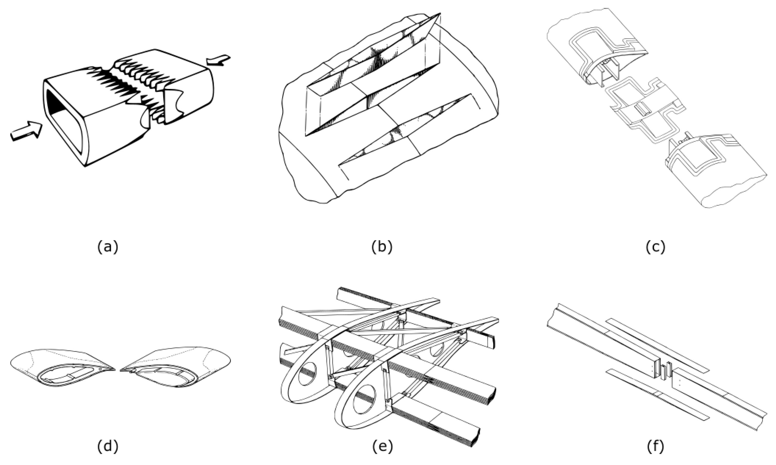
Blade segments can be joined using structural adhesive bonds. An overview is given in Figure 5. The efficiency of the joint depends on the chosen geometry. Finger joints were used in the wood-epoxy blades of the MOD-5A turbine (General Electic Company/NASA/DOE, USA) [92]. However, the use of this type of joint in modern fiberglass blades may be impeded by the higher modulus of elasticity and strains, as well as issues with tooling. Similarly, diamond-shaped splice-inserts can be adhered to the segments to form the joint [93]. Likewise, Bech [94] improved upon this approach by using longer connections providing higher stiffness and strength. Bhat [95] used finite element modeling to investigate the option of bonded strap plates. For general geometries, scarf joints and stepped lap joints have the highest efficiencies [96]. Concepts using scarf joints were suggested by various authors [84,85,86,89]. To avoid fragile protrusions, Hayden [97] proposed using a double scarf joint. Segmentation using stepped lap joints was suggested by Baker [83]. Further, Frederiksen [98] suggested not infusing the fibers in the joint areas when fabricating the segments, so that they can be joined by overlapping, infusing and curing the dry fibers.
7. Mechanical Joints in Segmented Blades
7.1. Cost of Energy
7.2. Experience from Blade Root Connections
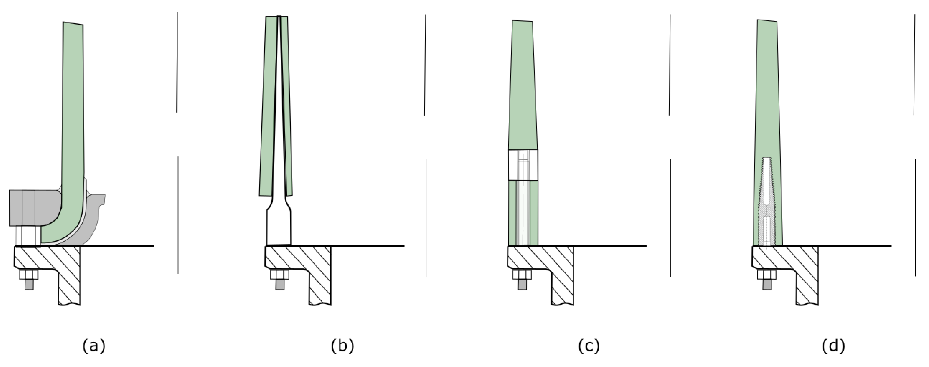
Conventionally, wind turbine blades are attached to a steel hub using a detachable mechanical joint. These root joints are highly loaded and experience a very high number of load cycles. Because of the existing experience in this field and the similarities with the joints for segmented blades, these joint types are candidates for blade segmentation. The most frequent root types are seen in Figure 6 and discussed in Table 4.
7.2.1. Flange Type
7.2.2. Hub Type
The hub-type root connection uses a tapered metal cylinder embedded or adhered to the root laminate and bolted to the hub. Assuring correct bond thickness is difficult, but critical for the performance of the joint [41]. Strain incompatibilities are present, resulting in large stress concentrations. Furthermore, in some implementations, the hub has a lower diameter than the actual root [99]. This reduces the second moment of area of the section through which the loads are transferred, reducing the structural efficiency of the joint. Hosseini-Toudeshky [101] investigated the progressive debonding of a hub-type joint using finite element methods. It was demonstrated that an overloading such as a gust can cause damage to the bonding of the root joint, which grows due to fatigue loading. The used method was able to predict the life reduction of this joint caused by various loadings.
7.2.3. T-Bolt Joint
T-bolt joints have cross-bolts positioned perpendicular to the root cylinder surface. Longitudinal bolts connect the hub to the cross-bolt [102]. T-bolts rely on the contact between the cross-bolt and the laminate to transfer loads. Martinez [103] investigated the T-bolt joint both numerically and with experiments and concluded that the T-bolt joint is reliable and inexpensive, but has a low structural efficiency, resulting in a high weight compared to other solutions such as inserts. Packing limitations exist and lead to a significant laminate build-up. Furthermore, the load factors of the bolts are critical to the integrity of the connection. Multiple improvements to the conventional T-bolt joint have been suggested. Harismendy [104] suggested the use of two longitudinal bolts for each cross bolt outside the blade laminate; while Quell [105] suggested using other shapes of cross bolts than cylindrical. Additionally, Doorenspleet [106] suggested using multi-row T-bolts in order to increase the packing limit.
7.2.4. Stud/Insert Type
The stud or insert root joint relies on longitudinal bolts attached to studs or inserts. Typically, the inserts are female threaded and made of steel, causing a thermal and flexural mismatch [107]. This is countered by tapering the studs on the out or inside and by using a thicker laminate [107]. Hayden [107] suggested to use a threaded insert made from a composite tube to improve compatibility to allow a reduced root wall thickness. Furthermore, to reduce the stress concentration at the tip of the inserts, Vronsky [108] suggested using inserts of different lengths. Often, the studs are glued into the blade. In wood composite blades, the studs are placed in holes that are drilled, while in glass fiber blades, the holes are preferably formed during fabrication [41,109]. Positioning of the stud is vital to the quality of the joint as a non-uniform adhesive thickness causes stress concentrations [110]. Typically, fixtures are used to position and bond the studs simultaneously. Often, the adhesive is injected into the hole around the insert by using a secondary hole or through the gap between the laminate and the stud. Alternatively, modified studs can allow the adhesive to flow through the center of the insert to form the bond through the stud [41]. Additionally, the joint quality can deteriorate because of macroscopic voids [41]. To avoid these voids, Raina [110] suggests to improve the tru-stud bonding method to allow vacuum infusion by adding a second channel to the stud. Alternatively, the studs can be directly embedded during the lamination process. This requires less fabrication process steps, tooling and allows the root laminate to be much thinner, but increases the complexity of the lamination process [41,111]. Sorensen [112] suggested using a holder with spaced recesses to hold the bushings. As an alternative, Bendel [113] and Kildegaard [114] both suggested inserts that can easily be positioned and form a smooth outer and inner surface onto which the fiber mats of the root laminate can be applied. In general, to provide sufficient pull-out strength, inserts have to be long. Various improvements have been suggested to increase the pull-out strength, allowing shorter, lighter inserts. Grove-Nielsen [115] suggested to include longitudinal grooves on the outside of the inserts to increase the contact area with the laminate. Further, in similarity with the Hütter root, Mcewen [111] proposed to capture the inserts mechanically by looping fibers around it. Additionally, Feigl [116] suggested putting fibers in between the inserts for a better contact, whereas Schmidt [117] suggested stitching together the fibers surrounding the bushings.
7.2.5. Comparison
The blade root design is mainly driven by cost, as it represents between seven percent and 20 percent of the total blade cost [103,118]. The weight of the joint is less important, since it is added close to the hub and the center of rotation. As a consequence, it does not have a big impact on the blade’s eigenfrequencies, and edge-wise and dynamic loads. This is different for blade segmentation joints, which are placed further outboard. Due to the superior fatigue performance of T-bolts and studs, other blade root designs have become rare. Jackson [119] performed the preliminary design of a 50-m blade. Blade roots were designed considering a T-bolt joint and a stud joint. The stud connection allowed a larger number of connections because of the packing limitations of T-bolts. This led to a reduced root laminate build-up resulting in a lower weight and price, despite more inexpensive T-bolt hardware.
7.2.6. Implementations in Segmented Blades
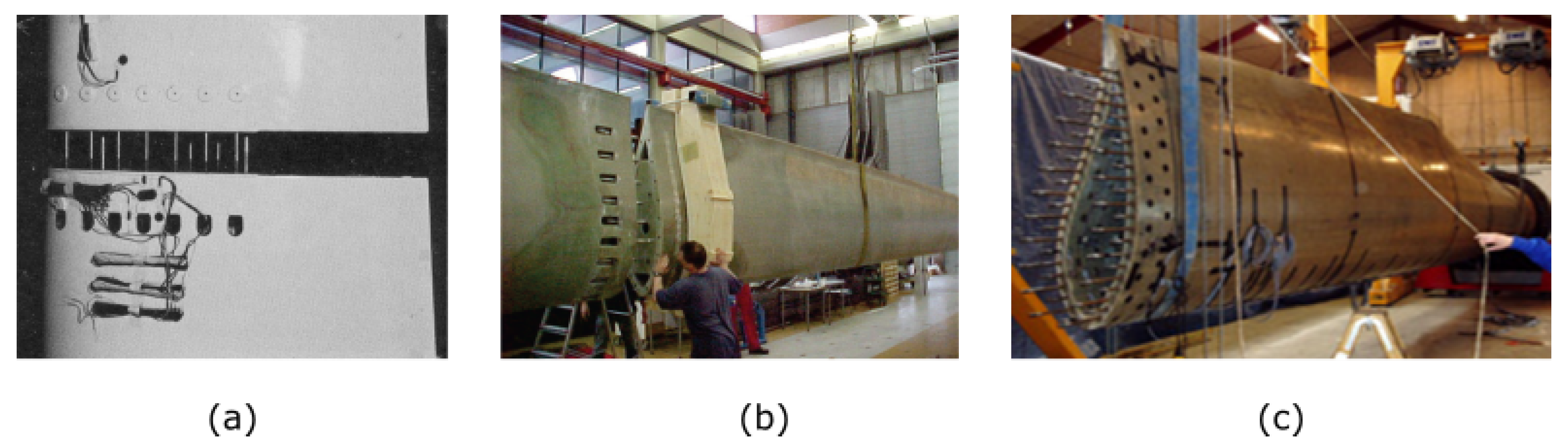
The T-bolt joint has been used in several prototype segmented blades, seen in Figure 7. It was first used on the DEBRA 25 wind turbine [100]. T-bolts joined the blades to the hub and connected the C-spars of the two 8.5-m blade segments. The turbine was successful and needed only limited additional maintenance to verify bolt pre-tension. Dutton [45] also investigated the use of a T-bolt joint for a segmented blade by using a single row of T-bolts in a prototype 23.3-m blade. The blade survived both static and fatigue testing. Later, Vionis [52] also investigated the use of a T-bolt joint by using a double row of T-bolts in a 30-m segmented blade. The blade survived static testing, but bolts at the spar caps failed during fatigue testing at one fifth of the 1E6 load cycles. Prototypes using inserts have also been made, as shown in Figure 8. Within the UpWind project, a 42.5-m sectional blade using inserts was developed [120]. Furthermore, Saenz [49,121] developed a joint for blade segmentation that increases the number of connections by alternating long and short bolts. The joint was used to design a 61.5-m segmented blade since this was the optimal location for blade transport.
7.3. Experience from Blade Root and Hub Extenders
To use existing blades on turbines at sites of a lower wind class than the blades were designed for, blade root extenders are placed in-between the hub and the blade roots, increasing the rotor diameter [122]. Blade extenders are generally made out of metal, but can also be manufactured from composite material [123]. They can incorporate a pre-coning [124] or sweep [125]. In a similar approach, the hub is extended, placing the pitching mechanism further out-board forming a hub extender or partial pitch system [50]. This concept was already used in the NASA Mod-2 turbine [126]. Lu [127] investigated a segmented blade of which the inboard portions were essentially blade extenders connected by a truss structure to reduce loads. Furthermore, to provide sufficient solidity at the blade root, an aerodynamic shape with a large chord length is required. This can be made feasible by using a root extender with an aerodynamic shape as suggested by Curtin [128]. An overview of these methods is shown in Figure 9.
7.4. Experience from Rotor Tips and Glider Wings
To reduce turbulence at the tips, aircraft often employ winglets. Similar tips are used on wind turbines to limit noise production [129]. However, such angled blade tips form delicate components during transportation and make manufacturing more complex and expensive. Therefore, they are often made as separate components and connected to the blades at the installation site. The blade tips can be connected by means of tubular guides and locked by means of a bolt, either transversely to the joint as suggested in Olthoff [129] or longitudinally as suggested in Hoffmann [130]. Furthermore, in the past, tip brakes were used to prevent over-speed on rotors with stall control [8,99,131]. These can rotate 90 degrees to create a drag. They are typically connected by means of a tube. Similarly, Moroz [50] suggested to alleviate loads with a segmented tip. In addition, the fabrication methods, structural layout and slenderness of gliders and wind turbine blades are similar, making joints used in gliders suitable candidates for blade segmentation [100]. Gliders often have detachable wings to allow easier transport and storage [132]. Modern glider carry-through structure configurations have one or two tongues next to each other to transfer bending loads [133]. Similar spar-bridge strategies with one or more protrusions have been suggested and tested for segmented blades. For example, Rudling [134] suggested a segmented blade that relies on joining the shear webs of a number of structural spars with shear pins. Loads are distributed using shear blocks attached to the webs. Segmented blades using spar-bridge joints were suggested in various studies [135,136,137,138]. Further, Dutton [45] designed and tested prototype of a segmented version of a 13.4-m blade with a connecting tube. The tube was attached to the blade using two bulkheads, similar to the concept suggested by Finnigan [139]. The blade underwent three static load tests (flap-wise towards the suction side and both edge-wise directions) followed by a five million cycle fatigue test in the flap-wise direction after which the static tests were repeated. It was concluded that no damage occurred in the blade, but that the loads were sometimes transmitted through the locking device instead of via the fitting, which had resulted in fretting corrosion.
7.5. Other Concepts
7.5.1. Cables
Some blade segmentation concepts cannot directly be traced back to a particular other application. An overview of these methods can be seen in Figure 10. There are a number of segmentation joints that rely on cables to form a connection. Wobben [140] suggested using pre-tensioned straps to hold together eccentric transversal bolts, attached to neighboring segments. However, due to friction, the pre-stress accuracy is limited and difficult to ensure [57]. Furthermore, this concept leads to high stress concentrations [90]. Alternatively, pre-tensioned cables can be used to hold the different segments together by pulling them towards the root. Kootstra [141] proposed to incorporate a joining segment that is pulled towards the root using a pre-tensioned cable. Similarly, in Doellinger [142], using pre-tensioned steel cables running through channels in the skin and shear webs as an alternative to a structural spar is suggested. The cables are attached at the blade root and fastening points on every blade segment. Likewise, Cairo [143] suggested using pre-tensioned cables running through conduits in the blade skin. Further, Klein [144] suggested using U-shaped cable loops embedded into the laminate.
7.5.2. Joints Using Transverse Fasteners
Joining the segments with fasteners in a transverse direction has also been considered. Torres [145] suggested joining the blades by riveting. Petri [56] suggested transversely bolting overlapping plates to the segments. To increase the laminate and bearing strength, Birkemeyer [60] suggested using fiber metal laminate (FML) in the region of the joint. Llorente [146] suggested using lugs to connect the spar of adjacent segments. These methods can be seen in Figure 11.
8. Conclusions
The feasibility of a segmented blade largely depends on the risk of the chosen concept. In this respect, concepts that require only limited changes from existing approaches pose less risk and are more likely to succeed. For example, concepts that do not require division of the blade’s main structural components, such as the use of separate leading or trailing edge segments, are only small modifications since these require only limited loads to be transmitted across the connections. For this reason, active trailing edge flaps are more likely to succeed than telescopic blades. Similarly, aerodynamically-shaped root extenders pose only a small modification from existing root extenders, which are well known in the industry. Furthermore, concepts incorporating a spar-bridge are close to joints used in sail-planes and tip brakes and have been shown to be feasible. Joints using longitudinal bolts have also been successful and are well known from the blade root design. The fact that large modern blades typically prefer the use of inserts to form a lightweight joint indicates that such joints are better suited for segmentation than flanged, hub-type and T-bolt joints. On the other hand, breaking up the blade’s main structural components poses significant challenges regarding production, maintenance costs and reliability. The failure of the T-bolt prototype blade in Vionis [52] and the unfavorable cost calculation for the T-bolt prototype blade in Dutton [45] indicate the difficulty of making this approach successful. Adhesive joints are also well known in the industry and are sometimes preferred because of their structural and economic efficiency [47]. However, the step from controlled conditions to in-field production of such connections is large. Yet, it may be possible to assemble the blade segments using local, perhaps temporary facilities. Furthermore, to avoid air entrapment, such adhesive joints would most likely be produced using vacuum infusion. The issues related to the manufacturing of larger blades are already being countered by manufacturing separate blade components. These are mostly assembled in the factory using either adhesive or mechanical joints. While blade segmentation poses serious challenges, the wide variety of possibilities and the potential benefits are bound to lead to further developments in this field. Furthermore, segmentation appears most likely to be cost effective for very large, offshore turbines or on-shore turbines with promising conditions, but accessibility issues.
Acknowledgments
The work leading to this publication has been supported by VLAIO(Flemish government agency for Innovation and Entrepreneurship) under the SBO“OptiWind: Serviceability optimisation of the next generation offshore wind turbines” (Project No. 120029).
Conflicts of Interest
The authors declare no conflict of interest. The founding sponsors had no role in the design of the study; in the collection, analyses or interpretation of data; in the writing of the manuscript; nor in the decision to publish the results.
References
- Kaldellis, J.K.; Zafirakis, D. The Wind Energy (r) Evolution: A Short Review of a Long History. Renew. Energy 2011, 36, 1887–1901. [Google Scholar] [CrossRef]
- Sieros, G.; Chaviaropoulos, P.; Sørensen, J.D.; Bulder, B.H.; Jamieson, P. Upscaling Wind Turbines: Theoretical and Practical Aspects and Their Impact on the Cost of Energy. Wind Energy 2012, 15, 3–17. [Google Scholar] [CrossRef]
- Campbell, S. Big Wind Turbines | Windpower Monthly. Available online: http://www.windpowermonthly.com/10-biggest-turbines (accessed on 14 July 2017).
- Lantz, E.; Wiser, R.; Hand, M. WP2 IEA Wind Task 26: The Past and Future Cost of Wind Energy; Technical Report NREL/TP-6A20-53510; National Renewable Energy Laboratory: Golden, CO, USA, 2012.
- Johnson, S.J.; Baker, J.P.; van Dam, C.P.; Berg, D. An Overview of Active Load Control Techniques for Wind Turbines with an Emphasis on Microtabs. Wind Energy 2010, 13, 239–253. [Google Scholar] [CrossRef]
- Caduff, M.; Huijbregts, M.A.J.; Althaus, H.J.; Koehler, A.; Hellweg, S. Wind Power Electricity: The Bigger the Turbine, The Greener the Electricity? Environ. Sci. Technol. 2012, 46, 4725–4733. [Google Scholar] [CrossRef] [PubMed]
- Thomsen, O.T. Sandwich Materials for Wind Turbine Blades—Present and Future. J. Sandw. Struct. Mater. 2009, 11, 7–26. [Google Scholar] [CrossRef]
- Hau, E. Wind Turbines; Springer: Berlin/Heidelberg, Germany, 2013. [Google Scholar]
- Nolet, S.C. Composite Wind Blade Engineering and Manufacturing; Independent Activities Period Mini-Course; Massachusetts Institute of Technology: Cambridge, MA, USA, 2011. [Google Scholar]
- Veers, P.S.; Ashwill, T.D.; Sutherland, H.J.; Laird, D.L.; Lobitz, D.W.; Griffin, D.A.; Mandell, J.F.; Musial, W.D.; Jackson, K.; Zuteck, M.; et al. Trends in the Design, Manufacture and Evaluation of Wind Turbine Blades. Wind Energy 2003, 6, 245–259. [Google Scholar] [CrossRef]
- Stiesdal, H.; Enevoldsen, P.B.; Johansen, K.; Kristensen, J.J.O.; Noertem, M.; Winther-Jensen, M. Method for Manufacturing Windmill Blades. E.P. Patent 1,310,351 (A1), 19 April 2006. [Google Scholar]
- Stiesdal, H. Method for Manufacturing a Wind Turbine Rotor Blade and Wind Turbine Rotor Blade. E.P. Patent 2,377,674 (A1), 19 October 2011. [Google Scholar]
- Serrano, J.C. Recovery Act: Wind Blade Manufacturing Innovation; Technical Report DE-EE0001372; U.S. Department of Energy: Washington DC, USA, 2011. [CrossRef]
- Mironov, G. A Wind Turbine Blade Automated Production System. W.O. Patent 2,011,035,539 (A1), 31 March 2011. [Google Scholar]
- Cooper, P. Wind Power Generation and Wind Turbine Design; Tong, W., Ed.; WIT Press: Southampton, UK; Boston, MA, USA, 2010. [Google Scholar]
- Banea, M.D.; da Silva, L.F.M. Adhesively Bonded Joints in Composite Materials: An Overview. Proc. Inst. Mech. Eng. Part L J. Mater. Des. Appl. 2009, 223, 1–18. [Google Scholar] [CrossRef]
- Hayden, P.; Broome, P. A Method of Making a Root End Joint of a Wind Turbine Blade and a Root Segment for Such a Joint. W.O. Patent 2,013,061,016 (A1), 2 May 2013. [Google Scholar]
- Griffin, D.A. Blade System Design Studies Volume I: Composite Technologies for Large Wind Turbine Blades; Technical Report SAND2002-1879; Sandia National Laboratories: Albuquerque, NM, USA, 2002. [CrossRef]
- Toft, H.S.; Branner, K.; Berring, P.; Sørensen, J.D. Defect Distribution and Reliability Assessment of Wind Turbine Blades. Eng. Struct. 2011, 33, 171–180. [Google Scholar] [CrossRef]
- Cairns, D.S.; Riddle, T.; Nelson, J. Wind Turbine Composite Blade Manufacturing: The Need for Understanding Defect Origins, Prevalence, Implications and Reliability; Technical Report SAND2011-1094; Sandia National Laboratories: Albuquerque, NM, USA, 2011.
- Andersen, S.; Albertsen, H.; Grabau, P. Windmill Rotor and Wind Blades Therefor. W.O. Patent 9,914,490 (A1), 25 March 1999. [Google Scholar]
- Hayden, P.T.; Behmer, H. A Modular Structural Composite Beam. W.O. Patent 2,011,135,306 (A1), 3 November 2011. [Google Scholar]
- Kontis, M.; Kulenkampff, J. Rotor Blade of a Wind Power Plant, Method of Fabricating a Rotor Blade and a Pair of Belts for a Rotor Blade. U.S. Patent 9,011,103 (B2), 21 April 2015. [Google Scholar]
- Sorensen, F.; Schytt-Nielsen, R.; Soerensen, F. Blade for a Wind Turbine and a Method of Assembling Laminated Profiles for a Blade. U.S. Patent 7,179,059 (B2), 20 February 2007. [Google Scholar]
- James, T.; Goodrich, A. Supply Chain and Blade Manufacturing Considerations in the Global Wind Industry; NREL/PR-6A20-60063; National Renewable Energy Laboratory: Golden, CO, USA, 2013.
- Smith, K. WindPACT Turbine Design Scaling Studies Technical Area 2: Turbine, Rotor, and Blade Logistics; Technical Report NREL/SR-500-29439; National Renewable Energy Laboratory: Kirkland, WA, USA, 2001.
- Flores, J.; Chan, S.; Homola, D. A Field Test and Computer Simulation Study on the Wind Blade Trailer. In Proceedings of the Fifth International Symposium on Highway Geometric Design, Vancouver, BC, Canada, 22–24 June 2015. [Google Scholar]
- García, E. Innoblade®: Gamesa’s Track Record on Blade Modularity. In Proceedings of the IQPC Conference “Advances in Rotor Blades for Wind Turbines”, Bremen, Germany, 25–27 February 2014. [Google Scholar]
- Grabau, P. Seaborne Transportation of Wind Turbine Blades. W.O. Patent 2,009,068,031 (A1), 4 June 2009. [Google Scholar]
- Rebsdorf, A.V. Transportation Method for a Wind Turbine Blade. U.S. Patent 2,012,227,357 (A1), 13 September 2012. [Google Scholar]
- Schibsbye, K.; Sullivan, J.T. Apparatus for Railroad Transportation of Wind Turbine Blades. U.S. Patent 8,641,339 (B2), 4 February 2014. [Google Scholar]
- Ashraf, S. Large Wind Turbine Blade Transportation Solution: The Aeroscraft. Wind Syst. 2013, 24–32. [Google Scholar]
- Cotrell, J.; Stehly, T.; Johnson, J.; Roberts, J.O.; Parker, Z.; Scott, G.; Heimiller, D. Analysis of Transportation and Logistics Challenges Affecting the Deployment of Larger Wind Turbines: Summary of Results; Technical Report NREL/TP-5000-61063; National Renewable Energy Laboratory: Golden, CO, USA, 2014.
- Jensen, J. A Method for the Transport of a Long Windmill Wing and a Vehicle for the Transport Thereof. W.O. Patent 2,006,000,230 (A1), 5 January 2006. [Google Scholar]
- Wobben, A. Transport Vehicle for a Rotor Blade of a Wind-Energy Turbine. W.O. Patent 03,057,528 (A1), 17 July 2003. [Google Scholar]
- Kawada, M. Transporting Method and Transporter of Irregular Shaped Elongated Article. J.P. 2,004,243,805 (A), 2 Sepember 2004. [Google Scholar]
- Nies, J. Transport Device for an Elongate Object Such as a Rotor Blade for a Wind Turbine or the Like. U.S. Patent 8,226,342 (B2), 24 July 2012. [Google Scholar]
- Pedersen, G. A Vehicle for Transporting a Wind Turbine Blade, a Control System and a Method for Transporting a Wind Turbine Blade. W.O. Patent 2,007,147,413 (A1), 27 December 2007. [Google Scholar]
- Landrum, S.C.; King, T.C. Wind Turbine Blade Transportation System and Method. U.S. Patent 7,591,621 (B1), 22 September 2009. [Google Scholar]
- Grabau, P. Transporting and Storing Curved Wind Turbine Blades. U.S. Patent 7,690,875 (B2), 6 April 2010. [Google Scholar]
- Berry, D.; Lockard, S.; Jackson, K.; Zuteck, M.; Ashwill, T. Blade Manufacturing Improvements Remote Blade Manufacturing Demonstration; Technical Report SAND2003-0719; Sandia National Laboratories: Warren, MI, USA, 2003.
- Pedersen, G.K.S. Vehicle for Transporting a Wind Turbine Blade, a Control System and a Method for Transporting a Wind Turbine Blade. U.S. Patent 8,306,695, 6 November 2012. [Google Scholar]
- Thomsen, J. Transport System for a Wind Turbine Blade. U.S. Patent 9,011,054 (B2), 21 April 2015. [Google Scholar]
- Fingersh, L.J.; Hand, M.M.; Laxson, A.S. Wind Turbine Design Cost and Scaling Model; Technical Report NREL/TP-500-40566; National Renewable Energy Laboratory: Golden, Co, USA, 2006.
- Dutton, A.; Kildegaard, C.; Kensche, C.; Hahn, F.; van Delft, D.; de Winkel, G. Design, Structural Testing, and Cost Effectiveness of Sectional Wind turbine Blades; Technical Report JOR3970167; Knowledge Centre WMC: Wieringerwerf, The Netherlands, 2000. [Google Scholar]
- Hibbard, P. Wind Turbine Blade. U.S. Patent 8,177,515 (B2), 15 May 2012. [Google Scholar]
- Wetzel, K.K. Modular Blade Design & Manufacturing, 2014; Wind Turbine Blade Workshop: Albuquerque, NM, USA, 2014.
- Nies, J.J. Adaptive Rotor Blade for a Wind Turbine. U.S. Patent 8,231,351, 31 July 2012. [Google Scholar]
- Saenz, E.; Nuin, I.; Montejo, R.; Sanz, J. Development and Validation of a New Joint System for Sectional Blades: Joint System for Sectional Blades. Wind Energy 2015, 18, 419–428. [Google Scholar] [CrossRef]
- Moroz, E.M. Multi-Piece Wind Turbine Rotor Blades and Wind Turbines Incorporating Same. U.S. Patent 7,381,029 (B2), 3 June 2008. [Google Scholar]
- Rohden, R. Rotor Blade for a Wind Energy Installation. W.O. Patent 2,007,131,937 (A1), 22 November 2007. [Google Scholar]
- Vionis, P.; Lekou, D.; Gonzalez, F.; Mieres, J.; Kossivas, T.; Soria, E.; Gutierrez, E.; Galiotis, C.; Philippidis, T.; Voutsinas, S.; et al. Development of a MW Scale Wind Turbine for High Wind Complex Terrain Sites; the MEGAWIND Project. In Proceedings of the EWEC, Athens, Greece, 27 February–2 March 2006; Volume 2006. [Google Scholar]
- Walters, A.E.D. Methods of Manufacture. U.S. Patent App. 13/576,931, 20 December 2012. [Google Scholar]
- Sayer, F.; Bürkner, F.; Blunk, M.; van Wingerde, A.M.; Busmann, H.G. Influence of Loads and Environmental Conditions on Material Properties over the Service Life of Rotor Blades. DEWI Mag. 2009, 34, 24–31. [Google Scholar]
- Pedersen, B.H.; De La Rua, I.A.; Sola, R.R.; Pascual, E.S.; Savii, H.R. Sensorised Blade Joint. U.S. Patent 20,090,116,962, 7 May 2009. [Google Scholar]
- Petri, L.; Sancho, R. Reversible System for Sectioning Wind Generator Blades in Several Parts. W.O. Patent 2,008,084,126 (B1), 12 September 2008. [Google Scholar]
- Stiesdal, H. Method and Connecting Piece for Assembling Windmill Blade Sections. W.O. Patent 2,006,056,584 (A1), 1 June 2006. [Google Scholar]
- Baker, M.L.; Arendt, C.P. Lightweight Composite Truss Wind Turbine Blade. U.S. Patent 7,517,198, 2 May 2013. [Google Scholar]
- Rudling, P. Wind Turbine Blade. U.S. Patent 8,696,317 (B2), 15 April 2014. [Google Scholar]
- Birkemeyer, J.; Beyland, L. Segmentation Technology for Large Onshore Blades. In Proceedings of the IQPC Conference “Advances in Rotor Blades for Wind Turbines”, Bremen, Germany, 25–27 February 2014. [Google Scholar]
- Wobben, A. Rotor Blade for a Wind Power Installation. W.O. Patent 02,051,730 (A3), 7 November 2002. [Google Scholar]
- Siegfriedsen, S. Rotor Blade for Wind Power Installations. W.O. Patent 0,146,582 (A2), 28 June 2001. [Google Scholar]
- Lachenal, X.; Daynes, S.; Weaver, P.M. Review of morphing concepts and materials for wind turbine blade applications. Wind Energ. 2012. [Google Scholar] [CrossRef]
- Niu, C.; Niu, M. Airframe Structural Design: Practical Design Information and Data on Aircraft Structures; Airframe Book Series; Conmilit Press Limited: Hong Kong, China, 1999. [Google Scholar]
- Griffin, D.A. WindPACT Turbine Design Scaling Studies Technical Area 1–Composite Blades for 80- to 120-Meter Rotor. Technical Report NREL/SR-500-29492; National Renewable Energy Laboratory: Golden, CO, USA, 2001. [Google Scholar]
- Schubel, P. Technical Cost Modelling for a Generic 45-m Wind Turbine Blade Producedby Vacuum Infusion (VI). Renew. Energy 2010, 35, 183–189. [Google Scholar] [CrossRef]
- Mikhail, A. Low Wind Speed Turbine Development Project Report; Technical Report NREL/SR-500-43743; National Renewable Energy Laboratory: Golden, CO, USA, 2009.
- Vronsky, T.; Hancock, M. Segmented Rotor Blade Extension Portion. W.O. Patent 2,010,013,025 (A3), 4 November 2010. [Google Scholar]
- Judge, P.W. Segmented Wind Turbine Blade. U.S. Patent 7,854,594 (B2), 21 December 2010. [Google Scholar]
- Broome, P.; Hayden, P. An Aerodynamic Fairing for a Wind Turbine and a Method of Connecting Adjacent Parts of Such a Fairing. W.O. Patent 2,011,064,553 (A3), 5 January 2012. [Google Scholar]
- Van Wingerde, A.M.; van Delft, D.R.V.; Molenveld, K.; Bos, H.L.; Bulder, B.H.; de Bonte, H. BLADECO Eindrapport; Technical Report BLDPV1-05; Knowledge Centre WMC: Wieringerwerf, The Netherlands, 2002. [Google Scholar]
- De La Rua, I.A.; Pascual, E.S.; Collado, S.A. Blade Insert. U.S. Patent 8,388,316, 5 March 2013. [Google Scholar]
- Mark, H. Modular Wind Turbine Blade with Both Spar and Foil Sections Forming Aerodynamic Profile. G.B. Patent 2,488,099 (A), 22 August 2012. [Google Scholar]
- Barlas, T.; van Kuik, G. Review of State of the Art in Smart Rotor Control Research for Wind Turbines. Prog. Aerosp. Sci. 2010, 46, 1–27. [Google Scholar] [CrossRef]
- Pasupulati, S.V.; Wallace, J.; Dawson, M. Variable Length Blades Wind Turbine. In Proceedings of the Power Engineering Society General Meeting, San Francisco, CA, USA, 16 June 2005; pp. 2097–2100. [Google Scholar]
- Dawson, M.H. Variable Length Wind Turbine Blade; Technical Report DE-FG36-03GO13171; U.S. Department of Energy Office of Energy Efficiency and Renewable Energy: Washington, DC, USA, 2006. [CrossRef]
- Imraan, M.; Sharma, R.N.; Flay, R.G. Wind Tunnel Testing of a Wind Turbine with Telescopic Blades: The Influence of Blade Extension. Energy 2013, 53, 22–32. [Google Scholar] [CrossRef]
- Dawson, M.; Wallace, J. Variable Length Wind Turbine Blade Having Transition Area Elements. W.O. Patent 2,010,120,595 (A1), 21 October 2010. [Google Scholar]
- Castaignet, D.; Barlas, T.; Buhl, T.; Poulsen, N.K.; Wedel-Heinen, J.J.; Olesen, N.A.; Bak, C.; Kim, T. Full-Scale Test of Trailing Edge Flaps on a Vestas V27 Wind Turbine: Active Load Reduction and System Identification: Full-Scale Test of Trailing Edge Flaps on a Vestas V27 Wind Turbine. Wind Energy 2014, 17, 549–564. [Google Scholar] [CrossRef]
- Berg, J.; Resor, B.; Paquette, J.; White, J. SMART Wind Turbine Rotor: Design and Field Test; SAND2014-0681; Sandia National Laboratories: Albuquerque, NM, USA, 2014.
- Berg, J.C.; Barone, M.F.; Yoder, N.C. SMART Wind Turbine Rotor: Data Analysis and Conclusions; SAND2014-0712; Sandia National Laboratories: Albuquerque, NM, USA, 2014.
- Tobergte, N.J. Apparatus and Method for Transporting and Aligning Wind Turbine Rotor Blade. U.S. Patent 8,172,493, 8 May 2012. [Google Scholar]
- Baker, M.; Arendt, C.; Madrid, B.; Vilhauer, S. Efficient Wind Turbine Blades, Wind Turbine Blade Structures, and Associated Systems and Methods of Manufacture, Assembly and Use. W.O. Patent 2010065928 (A1), 10 June 2010. [Google Scholar]
- Zirin, R.M.; Lin, W.W.L.; Zhou, Y.; Quek, S.C.; Praveen, G.; Kirkpatrick, B.; Livingston, J.T.; Baehmann, P.L. Multi-Segment Wind Turbine Blade and Method for Assembling the Same. U.S. Patent 7,740,453 (B2), 22 June 2010. [Google Scholar]
- Livingston, J.T. Structure and Method for Self-Aligning Rotor Blade Joints. U.S. Patent 8,167,569, 1 May 2012. [Google Scholar]
- Baehmann, P.L.; Miebach, T.; Telfeyan, E.J.; Lin, W.W.L.; Yerramalli, C.S.; Quek, S.C. Method for Assembling Jointed Wind Turbine Blade. U.S. Patent 2,010,132,884 (A1), 3 June 2010. [Google Scholar]
- Riddell, S.G. Joint Design for Rotor Blade Segments of a Wind Turbine. U.S. Patent 7,922,454 (B1), 12 April 2011. [Google Scholar]
- Kyriakides, S.A.; Riddell, S.G.; Walker, A.M. Method for Assembling a Multi-Segment Wind Turbine Rotor Blade with Span-Wise Offset Joints. U.S. Patent 2,013,091,705 (A1), 18 April 2013. [Google Scholar]
- Livingston, J.T.; Driver, H. Wind Blade Joint Bonding Grid. U.S. Patent 8,221,085, 17 July 2012. [Google Scholar]
- Arelt, R. Method for Producing a Rotor Blade, a Corresponding Rotor Blade and a Wind Power Plant. U.S. Patent 2,006,127,222 (A1), 15 June 2006. [Google Scholar]
- Driver, H.D.; Lin, W.W.; Livingston, J.T. Modular Wind Turbine Blades with Resistance Heated Bonds. U.S. Patent 2,009,148,300 (A1), 11 June 2009. [Google Scholar]
- Spera, D.A.; Esgar, J.B.; Gougeon, M.; Zuteck, M.D. Structural Properties of Laminated Douglas Fir/Epoxy Composite Material; National Aeronautics and Space Administration: Cleveland, OH, USA, 1990.
- Gougeon, M.A.; Gougeon, J.C. Wind Turbine Blade Joint Assembly and Method of Making Wind Turbine Blades. U.S. Patent 4,474,536 (A), 2 October 1984. [Google Scholar]
- Bech, A. Wind Turbine Blades Made of Two Separate Sections, and Method of Assembly. U.S. Patent 8,348,622 (B2), 8 January 2013. [Google Scholar]
- Bhat, C.; Noronha, D.J.; Saldana, F.A. Structural Performance Evaluation of Segmented Wind Turbine Blade Through Finite Element Simulation. Int. J. Mech. Aerosp. Ind. Mechatron. Manuf. Eng. 2015, 9, 996–1005. [Google Scholar]
- Schwartz, M.M. MIL-HDBK-17-3F: Composite Materials Handbook, Polymer Matrix Composites: Materials Usage, Design, and Analysis. In Composite Materials Handbook; U.S. Department of Defense: Arlington County, VA, USA, 2002; Volume 3. [Google Scholar]
- Hayden, P.; Behmer, H. A Wind Turbine Blade. W.O. Patent 2,012,004,571 (A3), 12 April 2012. [Google Scholar]
- Frederiksen, H. A Method of Producing a Composite Structure via Intermediate Products and a Composite Structure Obtainable by the Method. E.P. Patent 2,033,769 (A1), 11 March 2009. [Google Scholar]
- National Research Council. Assessment of Research Needs for Wind Turbine Rotor Materials Technology; National Academy Press: Washington, DC, USA, 1991. [Google Scholar]
- Kensche, C. Fatigue of Composites for Wind Turbines. Int. J. Fatigue 2006, 28, 1363–1374. [Google Scholar] [CrossRef]
- Hosseini-Toudeshky, H.; Jahanmardi, M.; Goodarzi, M. Progressive Debonding Analysis of Composite Blade Root Joint of Wind Turbines under Fatigue Loading. Compos. Struct. 2015, 120, 417–427. [Google Scholar] [CrossRef]
- Ashwill, T. Sweep-Twist Adaptive Rotor Blade: Final Project Report; Technical Report SAND2009-8037; Sandia National Laboratories: Albuquerque, NM, USA, 2010.
- Martínez, V.; Güemes, A.; Trias, D.; Blanco, N. Numerical and Experimental Analysis of Stresses and Failure in T-Bolt Joints. Compos. Struct. 2011, 93, 2636–2645. [Google Scholar] [CrossRef]
- Harismendy, R.D.A.; Amezqueta, P.; Sanz, M.; Nuin, M.; Lasa, M.; Sanz, R. Sistema De Amarre Para La Union De Tramos De Palas De Aerogenerador Partidas. E.S. Patent 2,352,945 (A1), 16 February 2011. [Google Scholar]
- Quell, P.; Bendel, U.; Schubert, M.; Eusterbarkey, C. Rotor Blade Attachment. U.S. Patent 8,133,029, 2 April 2012. [Google Scholar]
- Doorenspleet, F.; Arelt, R.; Eyb, E. Rotor Blade for a Wind Turbine. U.S. Patent 7,517,194 (B2), 14 April 2009. [Google Scholar]
- Hayden, P.; Broome, P.; Whiley, D. An Insert and Method for Forming an End Connection in a Uni -Axial Composite Material. W.O. Patent 2,010,041,008 (A1), 15 April 2010. [Google Scholar]
- Vronsky, T.; Hahn, F.H. Wind Turbine Rotor Blade. U.S. Patent 8,105,040, 31 January 2012. [Google Scholar]
- Faddoul, J.R. Test Evaluation of a Laminated Wood Wind Turbine Blade Concept; Technical Report DOE/NASA/ 20320-30; Lewis Research Center, National Aeronautics and Space Administration: Cleveland, OH, USA, 1981.
- Raina, A.; Wullenschneider, T.S.; Barnhart, R.M.; Wetzel, K.K.; Yang, C. Insert and Method of Attaching Insert to Structure. U.S. Patent 2,015,071,701 (A1), 12 March 2015. [Google Scholar]
- McEwen, L.N.; Louarn, F.H.; Sellier, J.; Chignell, A.J. Wind or Tidal Turbine Blade Having an Attachment. U.S. Patent 20,130,108,464, 2 May 2013. [Google Scholar]
- Sorensen, F.; Schytt-Nielsen, R.; Soerensen, F. Method of Manufacturing a Wind Turbine Blade Root. U.S. Patent 7,530,168 (B2), 12 May 2009. [Google Scholar]
- Bendel, U.; Werner, M.; Knops, M. Method for Establishing A Blade Connection of a Rotor Blade, A Blade Connection and a Securing Element for a Blade Connection. U.S. Patent 2,011,044,817 (A1), 24 February 2011. [Google Scholar]
- Kildegaard, C. Embedding Element to Be Embedded in the End Part of a Windmill Blade, a Method Producing Such an Embedding Element as Well as Embedding of Such Embedding Elements in a Windmill Blade. U.S. Patent 2,005,106,029 (A1), 19 May 2005. [Google Scholar]
- Grove-Nielsen, E. A Root Bushing for a Wind Turbine Rotor Blade, a Wind Turbine Rotor Blade, a Wind Turbine and a Method for Manufacturing a Wind Turbine Rotor Blade for a Wind Turbine. E.P. Patent 2,952,735 (A1), 9 December 2015. [Google Scholar]
- Feigl, L. Wind Turbine Blade Connector Assembly. W.O. Patent 2,013,014,228 (A1), 31 January 2013. [Google Scholar]
- Schmidt, R.; Weimer, C.; Stadtfeld, H. Blade Connection for the Rotor Blades of a Wind-Energy Turbine and a Method for the Production Thereof. W.O. Patent 03,082,551 (A1), 9 October 2003. [Google Scholar]
- Tangler, J.L. The Evolution of Rotor and Blade Design; National Renewable Energy Laboratory: Palm Springs, CA, USA, 2000.
- Jackson, K.J.; Zuteck, M.D.; van Dam, C.P.; Standish, K.J.; Berry, D. Innovative Design Approaches for Large Wind Turbine Blades. Wind Energy 2005, 8, 141–171. [Google Scholar] [CrossRef]
- UpWind: Design Limits and Solutions for Very Large Wind Turbines; Technical Report; European Wind Energy Association: Brussels, Belgium, 2011.
- Montejo, Y.; Amezqueta, P.; Lahuerata, C.; Nuin, M.D.L.; Guelbenzu, B.; Sanz, M.; Del, R.C.; Farinas, C.; Saenz, M. System for Joining Component Portions of Wind-Turbine Blades. W.O. Patent 2,012,156,547 (A1), 3 May 2012. [Google Scholar]
- Aarhus, K. Blade Root Extender for a Wind Turbine. U.S. Patent 8,337,161 (B2), 25 December 2012. [Google Scholar]
- Heerkes, H.; Scherer, R. Wind Turbine Rotor, and Hub and Extender Therefor. W.O. Patent 0,142,647 (A2), 14 June 2001. [Google Scholar]
- Wobben, A. Wind Turbine Blade Root Spacer for Increasing the Separation of the Blade Tip from the Tower. W.O. Patent 03,060,319 (A1), 24 July 2003. [Google Scholar]
- Joassard, R.; Bodin, P.; Filippi, G. Wind Generator for Power Plant, Has Offset Unit Offsetting Leading Edge Such That Main Axis Extended between Center of Root Base of Blades and Opposite Ends of Blades Does Not Pass through Rotational Axis of Hub. F.R. Patent 2,863,318 (A1), 10 June 2005. [Google Scholar]
- Linscott, B.S. DOE Large Horizontal Axis Wind Turbine Development at NASA Lewis Research Center; Technical Report DOE/NASA/20320-47; Lewis Research Center, National Aeronautics and Space Administration: Cleveland, OH, USA, 1982.
- Lu, H.; Zeng, P.; Lei, L.; Yang, Y.; Xu, Y.; Qian, L. A Smart Segmented Blade System for Reducing Weight of the Wind Turbine Rotor. Energy Convers. Manag. 2014, 88, 535–544. [Google Scholar] [CrossRef]
- Curtin, G.A. Expansion Assembly for a Rotor Blade of a Wind Turbine. U.S. Patent 20,110,142,636, 16 June 2011. [Google Scholar]
- Olthoff, G. Removable Rotor Blade Tip. U.S. Patent 20,130,236,321, 12 September 2013. [Google Scholar]
- Hoffmann, A.; Dulle, D.; Clemens, C. Rotor Blade Tip. U.S. Patent 2,016,090,963 (A1), 31 March 2016. [Google Scholar]
- Gay, P.L.; Gay, P.L. Wind Turbine Blade Tip Brake Apparatus and Method. U.S. Patent 8,403,641 (B2), 26 March 2013. [Google Scholar]
- Pajard, J.P. Aircraft Wing Including a Plurality of Dismountable Members. U.S. Patent 8,128,032, 6 March 2012. [Google Scholar]
- Thompson, B.E.; Lotz, R.D. Sailplane Carry-through Structures Made with Composite Materials. J. Aircraft 1996, 33, 596–600. [Google Scholar] [CrossRef]
- Rudling, P. A Root End Joint for a Wind Turbine Blade. W.O. Patent 2,009,034,292 (A2), 19 March 2009. [Google Scholar]
- Bech, A.; Hibbard, P. A Sectional Blade. W.O. Patent 2,010,023,299 (A2), 4 March 2010. [Google Scholar]
- Hibbard, P.; Hancock, M. Sectional Wind Turbine Blade. U.S. Patent 9,388,789 (B2), 12 July 2016. [Google Scholar]
- Eyb, E. Modular Rotor Blade for a Wind Turbine and Method for Assembling Same. U.S. Patent 7,654,799 (B2), 2 February 2010. [Google Scholar]
- Wang, W.; Jin, B.; Liu, Z.; Dang, Q.; Wang, S. Segmented Wind Rotor Blade for Wind Turbine Generator System and Assemblying Method Thereof. U.S. Patent 2,012,213,642 (A1), 23 August 2012. [Google Scholar]
- Finnigan, P.M.; Lanaud, C.; Rengarajan, G.; Qian, G. System and Method for Joining Turbine Blades. U.S. Patent 8,123,488 (B2), 28 February 2012. [Google Scholar]
- Wobben, A. Butt Connection for Hollow Profile Members. U.S. Patent 7,481,624, 27 January 2009. [Google Scholar]
- Kootstra, D.J. Wind Turbine Rotor Blade Joint. U.S. Patent 8,172,539, 8 May 2010. [Google Scholar]
- Doellinger, R.; Schindler, R.; Franz, D. Rotor Blade Comprising a Plurality of Individual Sections. U.S. Patent 4,389,162 (A), 21 June 1983. [Google Scholar]
- Cairo, R.R.; Cairo, R.R. Modular Blades and Methods for Making Same. U.S. Patent 7,393,184 (B2), 1 July 2008. [Google Scholar]
- Klein, H. Rotor Blade or Rotor Blade Segment for a Wind Turbine. U.S. Patent 8,888,462, 18 November 2014. [Google Scholar]
- Torres, M.M.; Torres, M. Pala De Aerogenerador Dividida En Tramos Y Proceso De Fabricacion De La Misma. E.S. Patent 2,343,712 (A1), 6 August 2010. [Google Scholar]
- Llorente, G.; Velez, O. Wind Turbine Blade. W.O. Patent 2,005,100,781 (A1), 27 October 2005. [Google Scholar]
Figure 1.
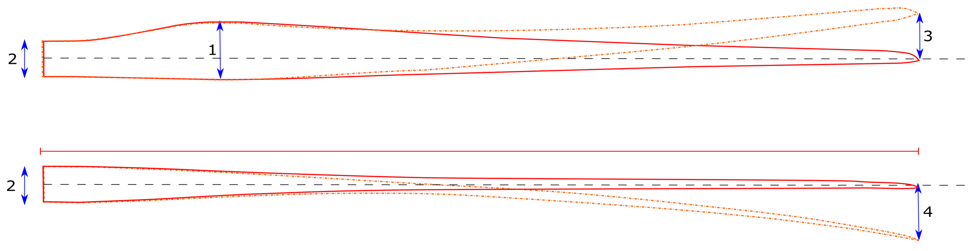
Top and side view of a modern wind turbine blade, giving an overview of blade transportation critical dimensions. The solid line shows a blade without pre-curving or sweep, while the dashed line shows a swept and pre-curved blade. (1) Maximum chord length. (2) Blade root diameter. (3) Blade sweep. (4) Blade pre-curving.
Figure 1.
Top and side view of a modern wind turbine blade, giving an overview of blade transportation critical dimensions. The solid line shows a blade without pre-curving or sweep, while the dashed line shows a swept and pre-curved blade. (1) Maximum chord length. (2) Blade root diameter. (3) Blade sweep. (4) Blade pre-curving.

Figure 2.
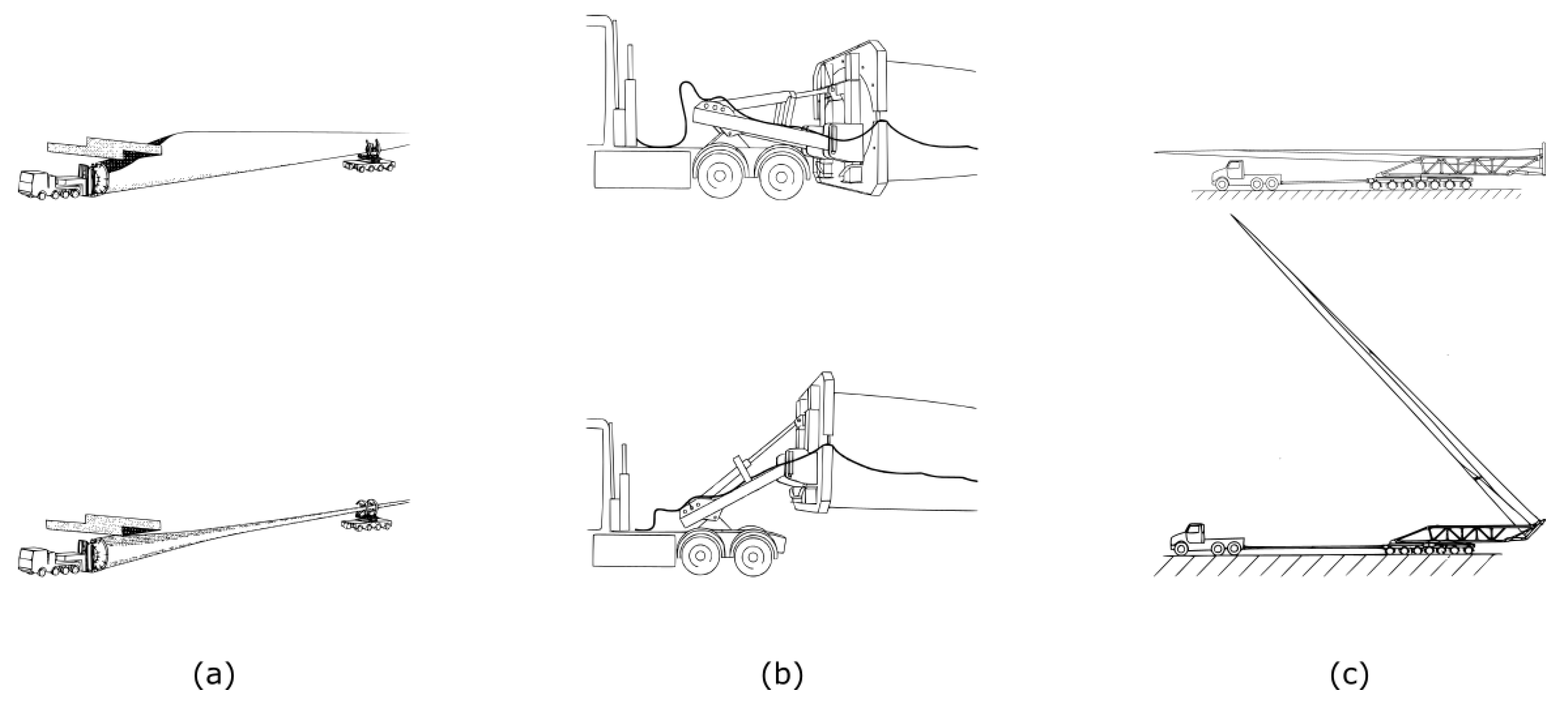
Blade road transportation solutions that temporarily change the way the blade is handled. (a) Solution where the blade can be rotated to pass under obstacles such as bridges or tunnels [35]. (b) System where the blade can be lifted to pass over low obstacles [34]. (c) System where the blade can be tilted at the root [42].
Figure 2.
Blade road transportation solutions that temporarily change the way the blade is handled. (a) Solution where the blade can be rotated to pass under obstacles such as bridges or tunnels [35]. (b) System where the blade can be lifted to pass over low obstacles [34]. (c) System where the blade can be tilted at the root [42].

Figure 3.
An overview of blade transportation solutions that deform the blade to ease transportation. (a) Straightening of the pre-curved blade to simplify transportation [40]. (b) Temporary deforming the blade to simplify transportation [43]. (c) Deforming the outboard portion of the blade during rail transportation to prevent overhang during turns [31].

Figure 4.
Different segmentation strategies. (a) Blade with a separate TE-segment to reduce the blades width [61]. (b) Blade with separate LEand TE panel segments to reduce the blade width [62]. (c) Blade divided to reduce the length of the components [46]. (d) Telescopic wind turbine blade [63]. (Reprint with permission [63]; 2012, John Wiley and Sons.)
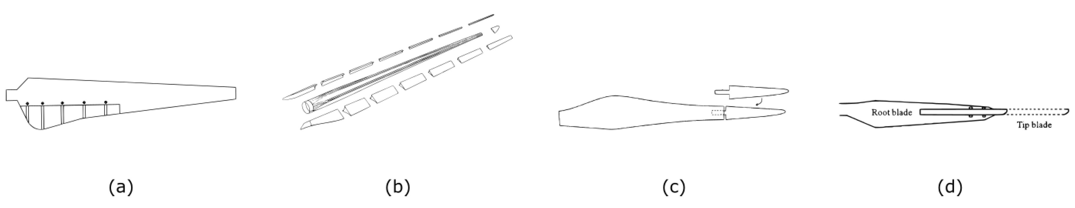
Figure 5.
Blade segmentation concepts using adhesive bonds. (a) Finger joint [99]. (b) Splice insert joint [92]. (c) Adhesive cavity joint [90]. (d) Single lap joint [87]. (e) Stepped lap joint [83]. (f) Double scarf joint [97].

Figure 6.
An overview of blade root joints. (a) Flange root connection. (b) Hub-type root connection. (c) T-bolt root connection. (d) Stud root connection.
Figure 6.
An overview of blade root joints. (a) Flange root connection. (b) Hub-type root connection. (c) T-bolt root connection. (d) Stud root connection.

Figure 7.
Prototype segmented blades using a T-bolt joint. (a) DEBRA-25 blade [100]. (Reprint with permission [100]; 2006, Elsevier.) (b) Split blade tested under the JOULEIII project [45]. (Reprint with permission [45]; 2000, Knowledge Centre WMC.) (c) Blade tested under the MEGAWIND project [52].

Figure 8.
Prototype segmented blades using inserts. (a) Blade joint developed during the UpWind project [55]. (b) Blade joint with alternating long and short bolts [49]. (Reprint with permission [49]; 2014, John Wiley and Sons.)
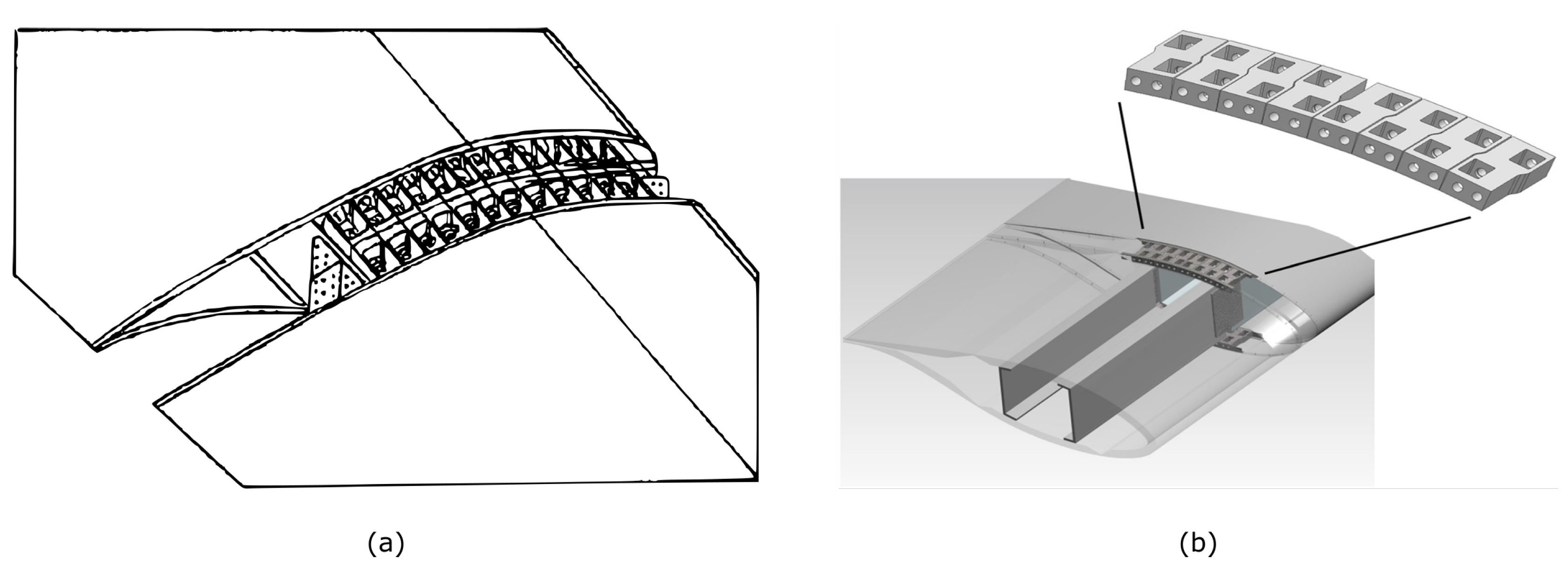
Figure 9.
Blade extension methods. (a) Blade root extender [122]. (b) Partial pitch mechanism [50]. (c) Blade root extender with an aerodynamic shape [128]. (d) Segmented blade with the inboard segment made from steel [51].

Figure 10.
Unique blade connections relying on cables to connect the different segments. (a) Blade using pre-tensioned steel cables to hold together the different segments as an alternative to a spar structure [142]. (b) Joint using pre-tensioned straps around eccentric bolts [140]. (c) U-shaped loops [144]. (d) Segmented blade joint relying on pre-tensioned cables to pull the outer segment towards the hub [141].

Figure 11.
Transverse joining concepts. (a) Segments joined with lugs [146]. (b) segments joined by intermediate pieces [56]. (c) segments joined with rivets [145].


Table 1.
Maximum allowed dimensions and weights for the transportation of wind turbine blades, based on [26].
Table 1.
Maximum allowed dimensions and weights for the transportation of wind turbine blades, based on [26].
| Transportation Method | Max. Weight (Tonne) | Max. Length (m) | Max. Height (m) | Max. Width (m) |
|---|---|---|---|---|
| rail | 163 | 27.4 | 4 | 3.4 |
| road (over weight) | >36 | 45.7 | 4.1 | 2.6 |
| water (barge) | >200 | 76.2 | - | 16.5 |
Table 2.
Overview of segmentation strategies.
| Segmentation Strategy | Type of Division | Advantages | Drawbacks |
|---|---|---|---|
| Reducing length | Span-wise joint | Potential cost reductions | Goes against historical trend |
| Slender blades reduce available space | |||
| Optimal split transport/structure differs | |||
| Division of structural spar | |||
| Reducing width/height | Chord-wise joint | Potential cost reductions | Transfer of edge-wise loads |
| Reducing rotor loading | Span-wise: telescopic blades | Variable swept area | Division of structural spar |
| Reduced extreme loads. | |||
| Chord-wise: trailing edge flaps | Variable blade shape | No need to divide structural spar | |
| Reduced extreme and fatigue loads | Increased complexity |
Table 3.
Overview of issues with the use of adhesive joints for segmented blades and the suggested remedies.
Table 3.
Overview of issues with the use of adhesive joints for segmented blades and the suggested remedies.
| Adhesive Joint Issue | Suggested Remedies | |
|---|---|---|
| Time of assembly | Alignment of the segments | -Alignment using laser-positioning |
| -Brackets attached to spar cap | ||
| -Alignment pins | ||
| -Overlapping portions | ||
| Curing of the bonds | -Resistance heated bonds | |
| Bond-quality | Bond thickness | -Bonding grid |
| -Shims | ||
| -Producing the segments in a single mold | ||
| Air entrapment | -Flooding of a cavity | |
| -Infusion |
Table 4.
Overview of joints used for segmented blades based on blade root connections.
| Blade Root Connection | Advantages | Drawbacks | Implementations |
|---|---|---|---|
| Flange type | - | Inferior fatigue behavior | - |
| Hub type | - | Heavy | - |
| T-bolt type | Inexpensive and simple | Packing limitation of the T-bolts | [45,52,100] |
| Stud/insert type | Allows for the lightest joint | cost | [49,55] |
© 2017 by the authors. Licensee MDPI, Basel, Switzerland. This article is an open access article distributed under the terms and conditions of the Creative Commons Attribution (CC BY) license (http://creativecommons.org/licenses/by/4.0/).
Share and Cite
MDPI and ACS Style
Peeters, M.; Santo, G.; Degroote, J.; Paepegem, W.V. The Concept of Segmented Wind Turbine Blades: A Review. Energies 2017, 10, 1112. https://doi.org/10.3390/en10081112
AMA Style
Peeters M, Santo G, Degroote J, Paepegem WV. The Concept of Segmented Wind Turbine Blades: A Review. Energies. 2017; 10(8):1112. https://doi.org/10.3390/en10081112
Chicago/Turabian StylePeeters, Mathijs, Gilberto Santo, Joris Degroote, and Wim Van Paepegem. 2017. "The Concept of Segmented Wind Turbine Blades: A Review" Energies 10, no. 8: 1112. https://doi.org/10.3390/en10081112
Note that from the first issue of 2016, this journal uses article numbers instead of page numbers. See further details here.