The Performance of a Direct Borohydride/Peroxide Fuel Cell Using Graphite Felts as Electrodes

1
Advanced Institute of Manufacturing with High-tech Innovations and Department of Mechanical Engineering, National Chung Cheng University, 168, University Rd., Minhsiung Township, Chiayi 62102, Taiwan
2
National Chung-Shan Institute of Science & Technology, Materials & Electro-Optics Research Division, P.O. Box No. 90008-8-2, Longtan, Taoyuan 32599, Taiwan
*
Author to whom correspondence should be addressed.
Energies 2017, 10(8), 1124; https://doi.org/10.3390/en10081124
Submission received: 24 June 2017
/
Revised: 20 July 2017
/
Accepted: 25 July 2017
/
Published: 1 August 2017
(This article belongs to the Special Issue Polymer Electrolyte Membrane Fuel Cells 2017)
Abstract
:A direct borohydride/peroxide fuel cell (DBPFC) generates electrical power by recirculating liquid anolyte and catholyte between the stack and reservoirs, which is similar to the operation of flow batteries. To enhance the accessibility of the catalyst layer to the liquid anolyte/catholyte, graphite felts are employed as the porous diffusion layer of a single-cell DBPFC instead of carbon paper/cloth. The effects of the type of anode alkaline solution and operating conditions, including flow rate and temperature of the anolyte/catholyte, on DBPFC performance are investigated and discussed. The durability of the DBPFC is also evaluated by galvanostatic discharge at 0.1 A∙cm−2 for over 50 h. The results of this preliminary study show that a DBPFC with porous graphite electrodes can provide a maximum power density of 0.24 W∙cm−2 at 0.8 V. The performance of the DBPFC drops slightly after 50 h of operation; however, the discharge capacity shows no significant decrease.
1. Introduction
Among the various types of fuel cell currently in existence, the direct borohydride/peroxide fuel cell (DBPFC), which operates with an aqueous solution of sodium borohydride (NaBH4) and hydrogen peroxide (H2O2), is considered a promising candidate for the power source of unmanned underwater vehicles (UUVs). This is because gas management for a conventional hydrogen/oxygen proton-exchange-membrane fuel cell (PEMFC) in a UUV remains a challenge. On the anode side of a DBPFC, NaBH4 can be oxidized directly in an alkaline medium to generate a maximum of eight electrons through the following reaction:
On the cathode side, H2O2 is reduced via the following reaction:
It can be seen that activation reduction of two-electron H2O2 has a lower activation barrier than that of four-electron O2, resulting in fast reaction kinetics. The overall reaction is
As a result, a DBPFC has a higher open-circuit voltage (2.11 V) than that of a PEMFC (1.23 V). In addition, DBPFC systems have several other advantages over conventional hydrogen/oxygen fuel cells, such as high energy density, long cycle life, easy fuel handling, and environmental safety.
Even though NaBH4 is dissolved in an alkaline media, a hydrolysis reaction and fuel crossover through the membrane can occur, resulting in fewer actual electrons being generated. To improve the electro-oxidation of borohydride, many published studies have investigated the development of anode catalytic materials, including Pt [1,2,3], Pd [3,4,5,6], Au [7,8,9], and Ni [10,11], unlike studies of solid oxide fuel cells (SOFCs), focusing on the cathode catalysts [12,13]. In most of those studies, the catalyst was coated on either carbon paper/cloth or a membrane that was sandwiched between two pieces of carbon paper or cloth as a membrane electrode assembly (MEA), which is the same structure as that used by MEAs for PEMFCs. The MEA was placed between anode and cathode graphite flow-field plates that are supplied with liquid NaBH4 and H2O2 solution, respectively.
Given that DBPFCs are fed with aqueous solutions, the cell performance is affected by the properties of the diffusion layer (DL). Park et al. [14] investigated the effects of the Polytetrafluoroethylene (PTFE) content and thickness of the DL on cell performance and suggested that thin DLs with high levels of wettability are desirable for the anode. Wang et al. [15] designed a two-part DL for the separate electro-oxidation of borohydride and hydrogen.
Flow fields play a key role in distributing aqueous solution and removing products from the MEA within a DBPFC. Raman et al. [16] employed stainless-steel blocks with machined flow fields for a six-cell DBPFC stack; the peak power density was 50 mW∙cm−2. Kim et al. [17] designed a DBPFC stack with a corrugated flow pattern on the anode and a parallel serpentine pattern on the cathode; the maximum power density of that stack was 183.8 mW∙cm−2. Khadke et al. [18] operated a DBPFC with double and single serpentine channels for the anode and cathode, respectively; that stack provided a maximum power density of 180 mW∙cm−2.
From the aforementioned literature, transport of aqueous solution within a DBPFC is also a key factor that influences its performance. However, the study of the MEA structure and flow-field pattern of a DBPFC is still limited. In this preliminary study, the performance of a DBPFC with a novel configuration involving graphite felts is investigated. The effects of flow rates and the types of anolyte and catholyte on the cell performance are analyzed. Finally, the durability of a DBPFC operated for 50 h is evaluated.
2. Experimental Details
2.1. Single-Cell Design
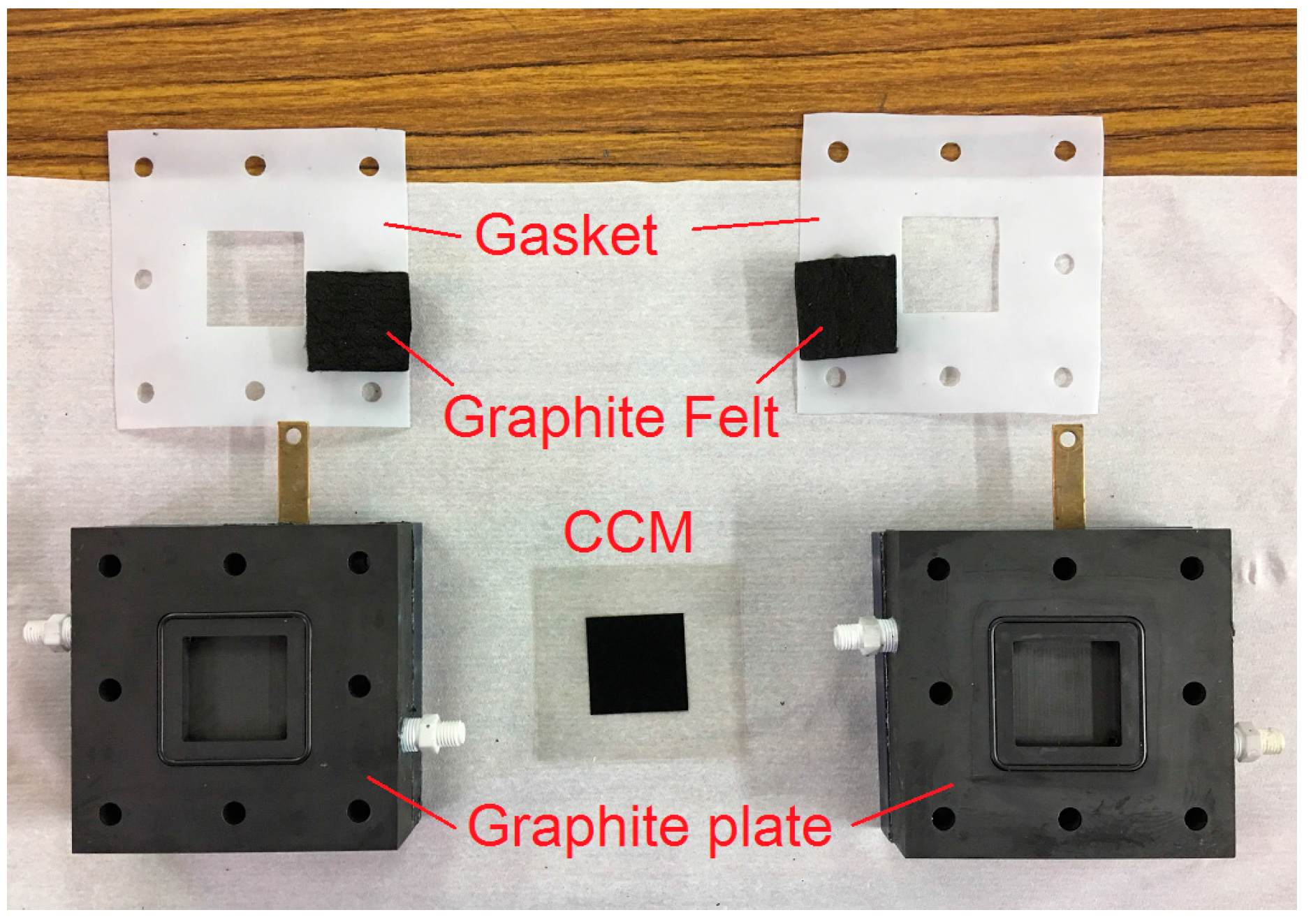
A single cell was prepared with an active area of 32 mm × 32 mm and a catalyst-coated membrane (CCM), porous electrodes, graphite plates, current collectors, and end plates, as shown in Figure 1. It can be seen that the configuration of the DBPFC is the same as that of a redox flow battery except for the CCM, which was fabricated by coating 1 mg∙cm−2 of Pt (TEC10E50E, 46.6% Pt/C, Tanaka, Tokyo, Japan) on a proton-exchange membrane (Nafion HP, Dupont, Wilmington, DE, USA) using an ultrasonic spraying system (Prism BT, USI, Haverhill, MA, USA). Two graphite felts (GFA10, SGL, Wiesbaden, Germany) with dimensions of 32 mm × 32 mm × 10 mm were pre-treated with 98% H2SO4 for 5 h and acted as DLs. The graphite plates were machined with a space of 32 mm × 32 mm × 5 mm for the DL. The current collectors were made of gold-plated copper, and the end plates were made of Polyvinyl chloride (PVC). Eight bolts were used to fix all components with a torque of 4 N∙m.
2.2. Experimental Procedure
The anolyte for the DBPFC was obtained by dissolving 10 g of NaBH4 and 20 g of KOH (or NaOH) in deionized (DI) water. The catholyte was composed of 5 g of H2O2 and 16.8 g of H2SO4. The anolyte and catholyte were each prepared as 50 mL solutions and were fed into the single cell by diaphragm pumps (SMART digital DDA7.5-16AR-PVC/V/C, Grundfos, Bjerringbro, Denmark). Both anolyte and catholyte were recirculated between the cell and their bottles with the same flow rate, namely, 20, 40, or 60 mL∙min−1. The temperature of the anolyte/catholyte solution was controlled by a hot plate (PC-420D, Corning, Corning, NY, USA) at an ambient temperature of ~22, 35, or 45 °C.
The performance was evaluated by measuring the polarization curve of the DBPFC using a battery tester (PFX2021, Kikusui, Yokohama, Japan). Such curves were measured successively without using fresh anolyte or catholyte (unless otherwise stated) to save on reactants. The load current density was increased in steps of 20 mA∙cm−2 from the open-circuit voltage to a cutoff voltage of 0.2 V. Each load current density lasted for 60 s before the next value. The duration of the DBPFC was evaluated by discharging it at a constant current density of 0.1 A∙cm−2 with a cutoff voltage of 0.2 V. At the end of each discharge, the DBPFC was purged with DI water to remove any residual anolyte and catholyte within the cell. The discharge was then started again with fresh anolyte and catholyte. An overall discharge time of more than 50 h was accumulated to evaluate the durability of the DBPFC.
3. Results and Discussion
3.1. Effect of Flow Rate
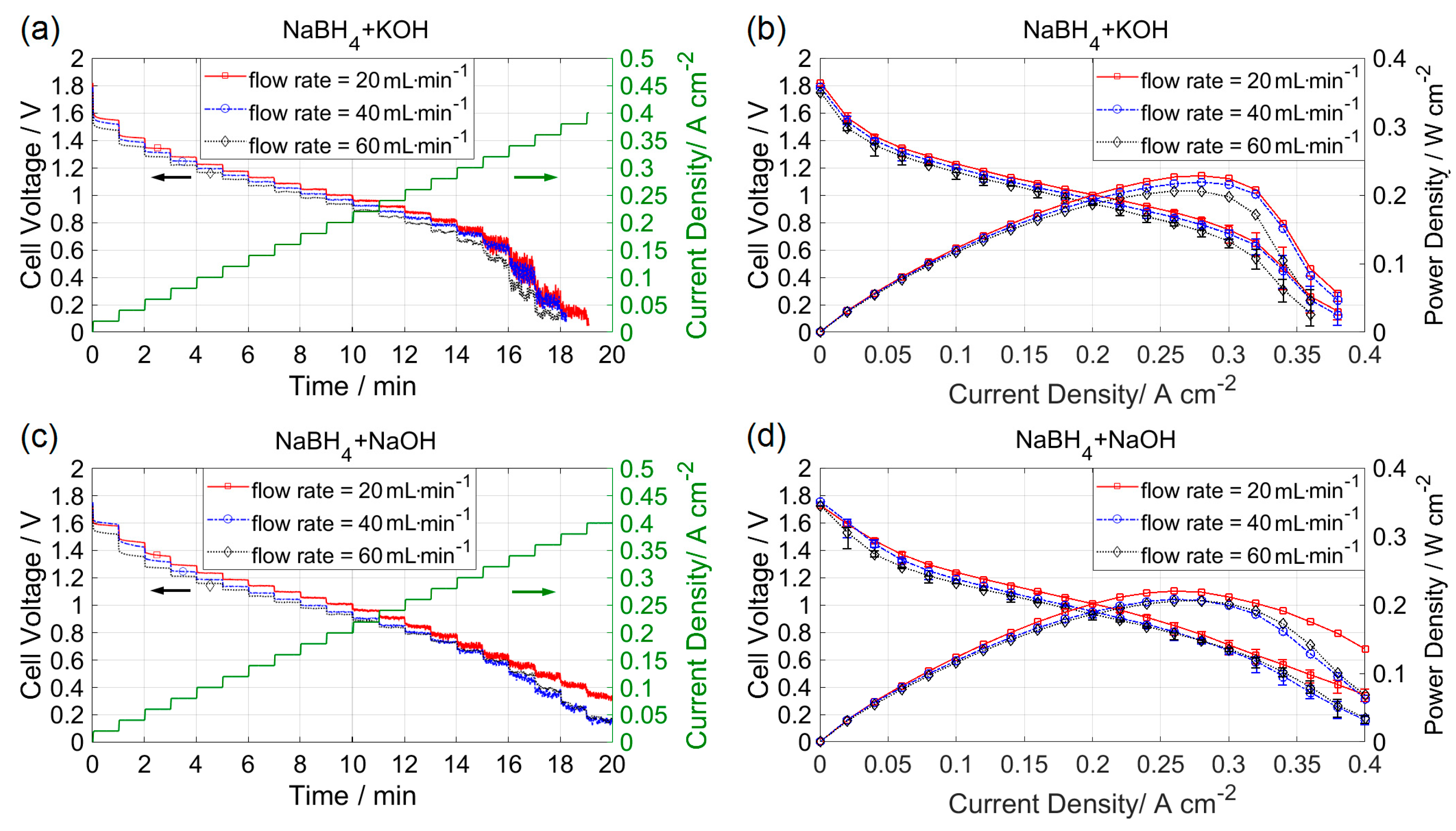
Figure 2a shows the effect of anolyte/catholyte flow rate on the DBPFC performance at ambient temperature when KOH served as the alkaline solution. Discharge began with a starting flow rate of 20 mL∙min−1, followed successively by 40 and 60 mL∙min−1. For current densities lower than 0.3 A∙cm−2, the cell voltage remained stable; however, it fluctuated considerably for current densities greater than 0.3 A∙cm−2. This could have been due to the fast consumption rate of NaBH4, and high production rate of NaBO2, resulting in the deterioration of electrochemical reaction on the catalyst layer. Each polarization curve was plotted by taking the average cell voltage with respect to each current density level, as shown in Figure 2b. The maximum power density was approximately 0.24 W∙cm−2 at 0.8 V, which was higher than results in other published works [16,17,18]. Because the porosity of graphite felts was higher than that of carbon paper/cloth, the transport of aqueous anolyte/catholyte was enhanced in the DBPFC of this study, resulting in improved performance.
The performance curves decreased slightly with increasing anolyte/catholyte flow rate. This drop may have been caused by a decreased concentration of the anolyte/catholyte due to discharge. Theoretically, the energy capacity of the 5 g of NaBH4 prepared for the anolyte is 28.34 Ah, whereas the energy capacity consumed in measuring each polarization curve is calculated as 0.57 Ah by the equation
resulting in a decrease in energy capacity of approximately 2%.
However, when the anolyte/catholyte flow rate was increased from 20 to 60 mL∙min−1, there was no significant increase in the performance curve. The effect of flow rate on a DBPFC is not noticeable in this study. The possible reason is the large ratio of the DL thickness to the active area, providing much space for the electrolyte to flow through; thus, increased flow rate showed little effect on the electrochemical reaction taking place on the thin catalyst layer. When NaOH served as the alkaline solution, the cell voltage in the concentration overpotential region was higher than that with KOH, as shown in Figure 2c. A similar result was observed in the work published by Santos et al. [19]. However, the maximum power density was approximately 0.23 W∙cm−2 at 0.8 V, as shown in Figure 2d, which is similar to that when KOH was used as the anolyte.
3.2. Effect of Electrolyte Temperature
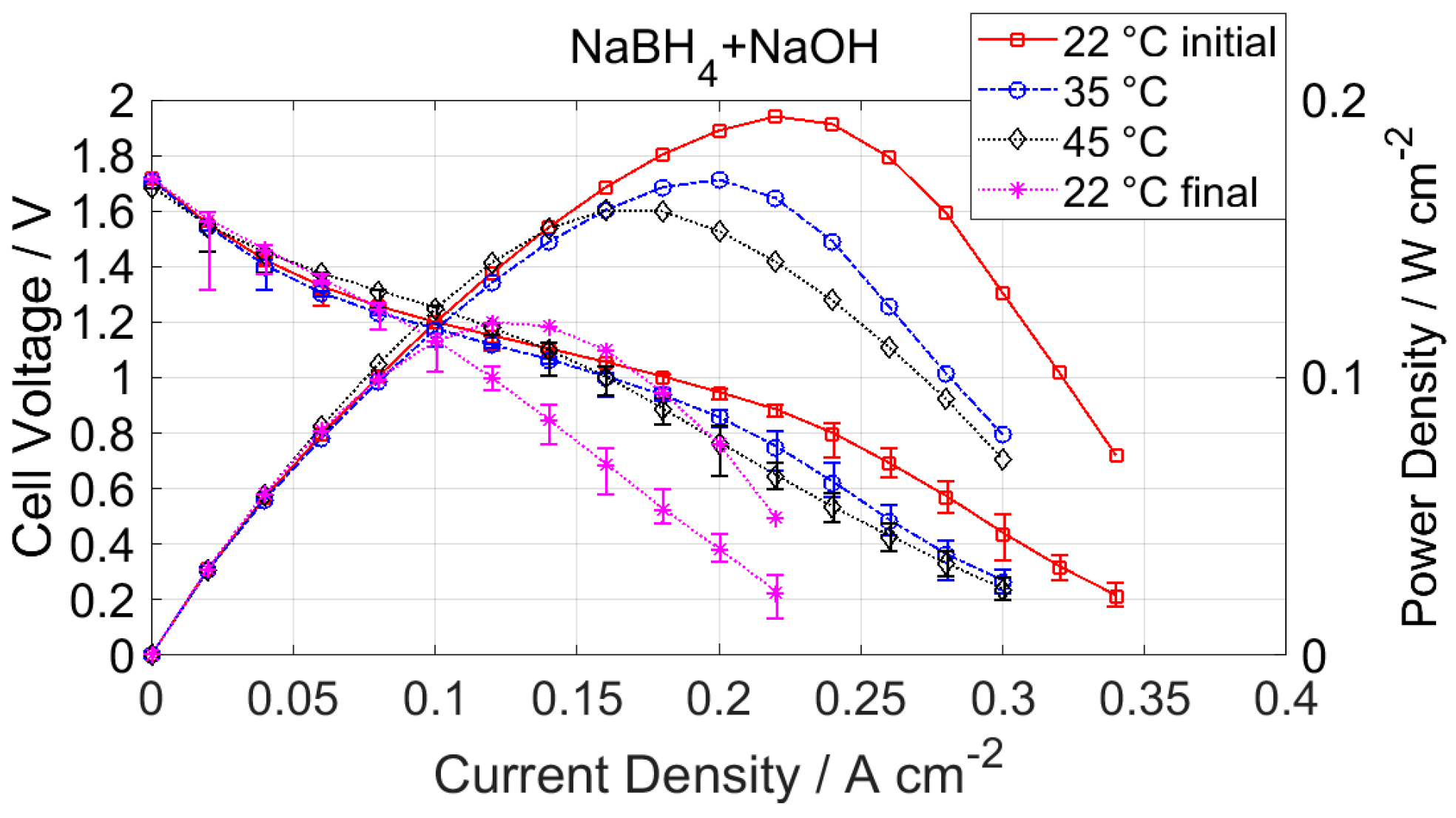
Figure 3 shows polarization curves of the DBPFC when the anolyte and catholyte were controlled at various temperatures. Because of the liquid temperature limit of the recirculation pumps, the anolyte and catholyte temperatures were controlled below 45 °C; each experiment started at 22 °C, followed by 35 and 45 °C. The performance of the DBPFC was measured again after the anolyte and catholyte had cooled down. The performance showed insignificant improvement for current densities lower than 0.15 A∙cm−2; otherwise, high temperatures tended to mitigate the performance. Even when the temperature was decreased to 22 °C, the cell performance did not recover. This was caused by the increased rate of decomposition of the anolyte and catholyte at high temperature [20], a situation that is therefore necessary to avoid.
3.3. Durability Analysis
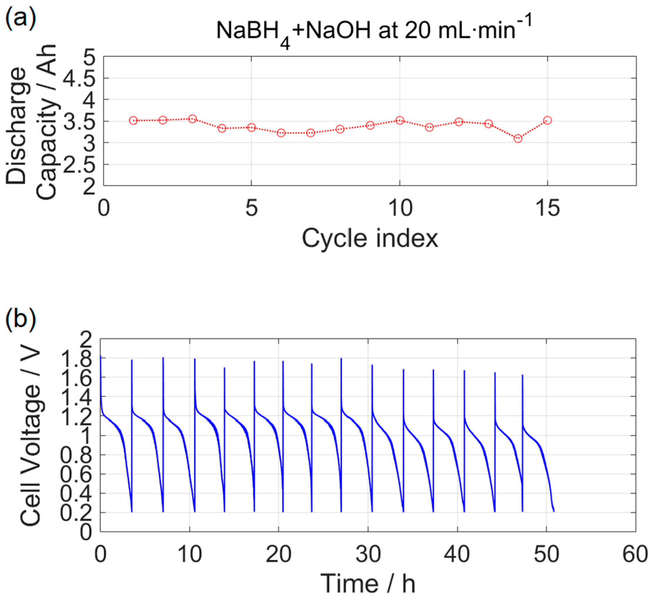
The variations in discharge capacity and cell voltage for durability analysis are shown in Figure 4. The time for a single discharge was 3.0–3.5 h, resulting in a discharge capacity of 3.0–3.5 Ah, as shown in Figure 4a. Such differences could have been due to a difference in ambient temperature between cycles. The discharge efficiencies were calculated as 11–12.4% when compared with the theoretical value of 28.34 Ah using 5 g of NaBH4. It can be observed that the discharge efficiency varied slightly with discharge cycle, but did not drop significantly.
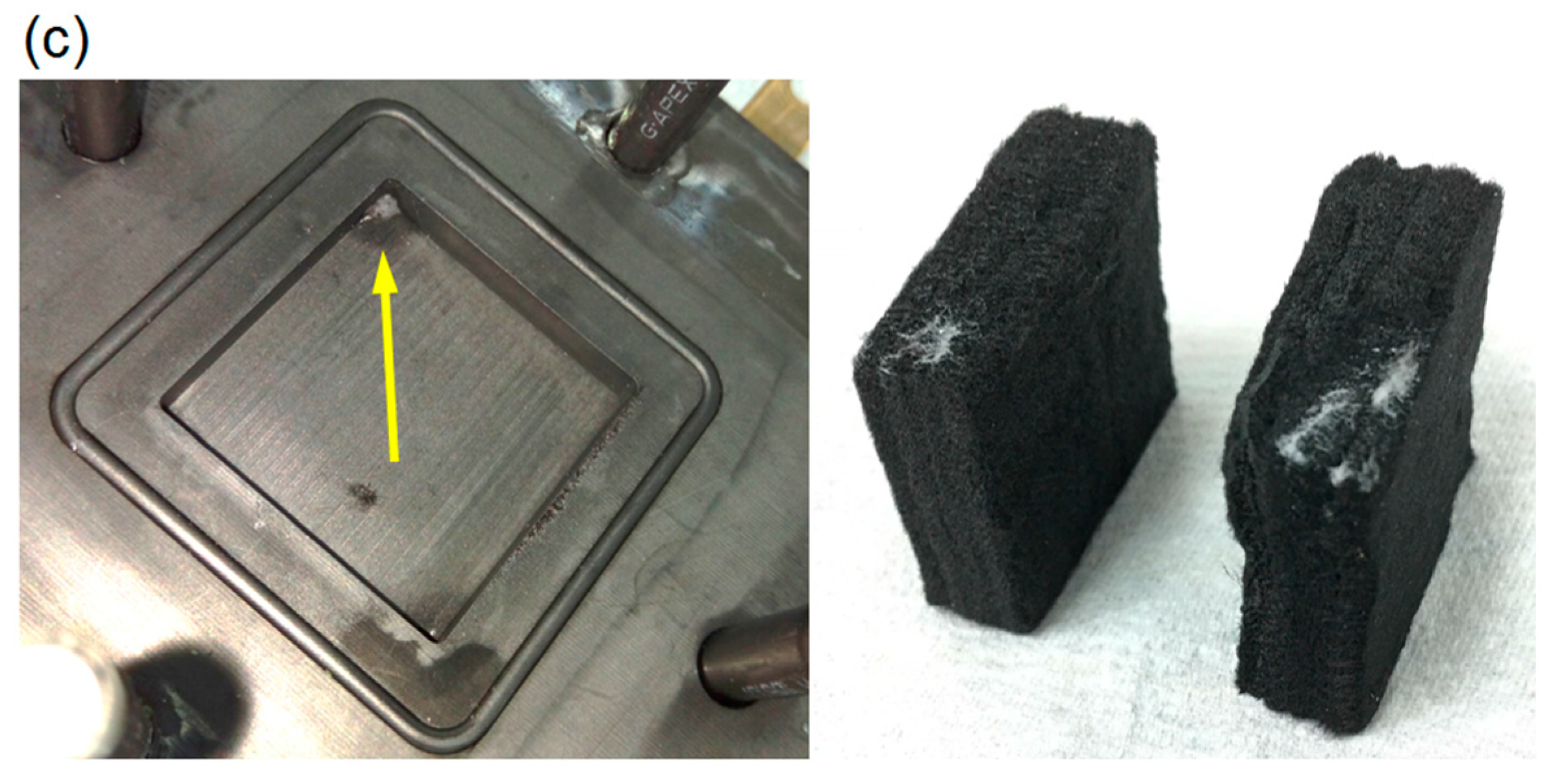
The variation of cell voltage with operation time is shown in Figure 4b. Before the 30 h mark, the initial voltage during discharge was higher than 1.2 V and then dropped to approximately 1.1 V thereafter. The DBPFC was operated in the ohmic region when the current density was 0.1 A∙cm−2. Figure 4c shows the CCM and graphite felts disassembled from the DBPFC after 50 h of operation. The whitish material that can be seen in the graphite felts was due to crossover of NaBH4 or NaBO2 from the anode [21], resulting in the performance drop. Accordingly, preventing accumulation of sodium borate in the DL would help stabilization for long-term operation.
4. Conclusions
In this preliminary study, a DBPFC was fabricated to have the same configuration as a redox flow battery, with graphite felts as the DLs. The performance of the DBPFC was evaluated under various operating conditions, and the following conclusions are drawn.
- The DBPFC with NaOH as the anolyte demonstrated more stable performance in the concentration overpotential region than the one using KOH as the anolyte.
- The anolyte/catholyte flow rate showed no significant effect on the DBPFC performance due to the large ratio of DL thickness to active area in this study.
- A maximum power density of 0.24 W∙cm−2 was obtained in the DBPFC with graphite felts as the DLs.
- After 50 h of galvanostatic operation, the DBPFC showed a slight drop in performance as a result of the accumulation of sodium borate in the graphite felts.
Acknowledgments
The authors would like to acknowledge financial support from the Ministry of Science and Technology, Taiwan, ROC under the project number MOST-105-2221-E-194-044-MY3 for this study.
Author Contributions
All authors read and approved the manuscript. Heng-Yi Lee and Yi-Hsuan Hsu performed experiments and plotted experimental data. Po-Hong Tsai programmed a test schedule to control electronic load. Jiunn-Yih Lee thoroughly reviewed literature and provided precious advice on the structure of this article. Yong-Song Chen provided the main idea of the work and prepared the manuscript.
Conflicts of Interest
The authors declare no conflict of interest.
References
- Liu, X.; Yi, L.; Wang, X.; Su, J.; Song, Y.; Liu, J. Graphene supported platinum nanoparticles as anode electrocatalyst for direct borohydride fuel cell. Int. J. Hydrog. Energy 2012, 37, 17984–17991. [Google Scholar] [CrossRef]
- Briega-Martos, V.; Herrero, E.; Feliu, J.M. Borohydride electro-oxidation on Pt single crystal electrodes. Electrochem. Commun. 2015, 51, 144–147. [Google Scholar] [CrossRef] [Green Version]
- Olu, P.-Y.; Gilles, B.; Job, N.; Chatenet, M. Influence of the surface morphology of smooth platinum electrodes for the sodium borohydride oxidation reaction. Electrochem. Commun. 2014, 43, 47–50. [Google Scholar] [CrossRef]
- Olu, P.-Y.; Deschamps, F.; Caldarella, G.; Chatenet, M.; Job, N. Investigation of platinum and palladium as potential anodic catalysts for direct borohydride and ammonia borane fuel cells. J. Power Sources 2015, 297, 492–503. [Google Scholar] [CrossRef]
- De Ponce León, C.; Walsh, F.C.; Patrissi, C.J.; Medeiros, M.G.; Bessette, R.R.; Reeve, R.W.; Lakeman, J.B.; Rose, A.; Browning, D. A direct borohydride-peroxide fuel cell using a Pd/Ir alloy coated microfibrous carbon cathode. Electrochem. Commun. 2008, 10, 1610–1613. [Google Scholar] [CrossRef]
- Yi, L.; Song, Y.; Wang, X.; Yi, L.; Hu, J.; Su, G.; Yi, W.; Yan, H. Carbon supported palladium hollow nanospheres as anode catalysts for direct borohydride-hydrogen peroxide fuel cells. J. Power Sources 2012, 205, 63–70. [Google Scholar] [CrossRef]
- Lima, F.H.B.; Pasqualeti, A.M.; Molina Concha, M.B.; Chatenet, M.; Ticianelli, E.A. Borohydride electrooxidation on Au and Pt electrodes. Electrochim. Acta 2012, 84, 202–212. [Google Scholar] [CrossRef]
- Pei, F.; Wang, Y.; Wang, X.; He, P.Y.; Liu, L.; Xu, Y.; Wang, H. Preparation and performance of highly efficient Au nanoparticles electrocatalyst for the direct borohydride fuel cell. Fuel Cells 2011, 11, 595–602. [Google Scholar] [CrossRef]
- He, P.; Wang, X.; Fu, P.; Wang, H.; Yi, L. The studies of performance of the Au electrode modified by Zn as the anode electrocatalyst of direct borohydride fuel cell. Int. J. Hydrog. Energy 2011, 36, 8857–8863. [Google Scholar] [CrossRef]
- Hosseini, M.G.; Abdolmaleki, M. Synthesis and characterization of porous nanostructured Ni/PdNi electrode towards electrooxidation of borohydride. Int. J. Hydrog. Energy 2013, 38, 5449–5456. [Google Scholar] [CrossRef]
- Hasan, M.; Newcomb, S.B.; Rohan, J.F.; Razeeb, K.M. Ni nanowire supported 3D flower-like Pd nanostructures as an efficient electrocatalyst for electrooxidation of ethanol in alkaline media. J. Power Sources 2012, 218, 148–156. [Google Scholar] [CrossRef]
- Seymour, I.D.; Chroneos, A.; Kilner, J.A.; Grimes, R.W. Defect processes in orthorhombic LnBaCo2O5.5 double perovskites. Phys. Chem. Chem. Phys. 2011, 13, 15305–15310. [Google Scholar] [CrossRef] [PubMed]
- Seymour, I.D.; Tarancón, A.; Chroneos, A.; Par, D.; Kilner, J.A.; Grimes, R.W. Anisotropic oxygen diffusion in PrBaCo2O5.5 double perovskites. Solid State Ion. 2012, 216, 41–43. [Google Scholar] [CrossRef]
- Park, K.T.; Jung, U.H.; Jeong, S.U.; Kim, S.H. Influence of anode diffusion layer properties on performance of direct borohydride fuel cell. J. Power Sources 2006, 162, 192–197. [Google Scholar] [CrossRef]
- Wang, G.; Gao, Y.; Wang, Z.; Du, C.; Yin, G. A membrane electrode assembly with high fuel coulombic efficiency for passive direct borohydride fuel cells. Electrochem. Commun. 2010, 12, 1070–1073. [Google Scholar] [CrossRef]
- Raman, R.K.; Prashant, S.K.; Shukla, A.K. A 28-W portable direct borohydride-hydrogen peroxide fuel-cell stack. J. Power Sources 2006, 162, 1073–1076. [Google Scholar] [CrossRef]
- Kim, C.; Kim, K.-J.; Ha, M.Y. Investigation of the characteristics of a stacked direct borohydride fuel cell for portable applications. J. Power Sources 2008, 180, 114–121. [Google Scholar] [CrossRef]
- Khadke, P.S.; Sethuraman, P.; Kandasamy, P.; Parthasarathi, S.; Shukla, A.K. A self-supported direct borohydride-hydrogen peroxide fuel cell system. Energies 2009, 2, 190–201. [Google Scholar] [CrossRef]
- Santos, D.M.F.; Condeço, J.A.D.; Franco, M.W.; Sequeira, C.A.C. An Improved Borohydride-H2O2 Laboratory Fuel Cell. ECS Trans. 2007, 3, 19–30. [Google Scholar] [CrossRef]
- Gu, L.; Luo, N.; Miley, G.H. Cathode electrocatalyst selection and deposition for a direct borohydride/hydrogen peroxide fuel cell. J. Power Sources 2007, 173, 77–85. [Google Scholar] [CrossRef]
- Jamard, R.; Salomon, J.; Martinent-Beaumont, A.; Coutanceau, C. Life time test in direct borohydride fuel cell system. J. Power Sources 2009, 193, 779–787. [Google Scholar] [CrossRef]
Figure 1.
Components of a single-cell direct borohydride/peroxide fuel cell used in this study.

Figure 2.
Performance curves of a direct borohydride/peroxide fuel cell (DBPFC) operated with different anolyte compositions at various flow rates. (a) Cell voltage with respect to time (NaBH4 in KOH solution); (b) cell voltage with respect to current (NaBH4 in KOH solution); (c) cell voltage with respect to time (NaBH4 in NaOH solution); and (d) cell voltage with respect to current (NaBH4 in NaOH solution).

Figure 3.
Effect of anolyte and catholyte temperatures on the performance of the DBPFC.

Figure 4.
Durability analysis. (a) Discharge capacity variation with respect to cycling index; (b) voltage variation of the DBPFC under a constant load of 100 mA∙cm−2 as a function of time; (c) photographs of components after 50 h of operation.
Figure 4.
Durability analysis. (a) Discharge capacity variation with respect to cycling index; (b) voltage variation of the DBPFC under a constant load of 100 mA∙cm−2 as a function of time; (c) photographs of components after 50 h of operation.
© 2017 by the authors. Licensee MDPI, Basel, Switzerland. This article is an open access article distributed under the terms and conditions of the Creative Commons Attribution (CC BY) license (http://creativecommons.org/licenses/by/4.0/).
Share and Cite
MDPI and ACS Style
Lee, H.-Y.; Hsu, Y.-H.; Tsai, P.-H.; Lee, J.-Y.; Chen, Y.-S. The Performance of a Direct Borohydride/Peroxide Fuel Cell Using Graphite Felts as Electrodes. Energies 2017, 10, 1124. https://doi.org/10.3390/en10081124
AMA Style
Lee H-Y, Hsu Y-H, Tsai P-H, Lee J-Y, Chen Y-S. The Performance of a Direct Borohydride/Peroxide Fuel Cell Using Graphite Felts as Electrodes. Energies. 2017; 10(8):1124. https://doi.org/10.3390/en10081124
Chicago/Turabian StyleLee, Heng-Yi, Yi-Hsuan Hsu, Po-Hong Tsai, Jiunn-Yih Lee, and Yong-Song Chen. 2017. "The Performance of a Direct Borohydride/Peroxide Fuel Cell Using Graphite Felts as Electrodes" Energies 10, no. 8: 1124. https://doi.org/10.3390/en10081124
Note that from the first issue of 2016, this journal uses article numbers instead of page numbers. See further details here.