Article

Maximum Power Point Tracking of Photovoltaic Panels by Using Improved Pattern Search Methods

by
Andrés Tobón
1,
Julián Peláez-Restrepo
1,
Juan P. Villegas-Ceballos
1,
Sergio Ignacio Serna-Garcés
1,
Jorge Herrera
2,* and
Asier Ibeas
2,3
1
Departamento de Electrónica y Telecomunicaciones, Facultad de Ingenierías, Instituto Tecnológico Metropolitano, Medellín, Antioquia, Colombia
2
Departamento de Ingeniería, Facultad de Ciencias Naturales e Ingeniería, Universidad de Bogotá Jorge Tadeo Lozano, Bogotá, Distrito Capital, Colombia
3
Departament de Telecomunicació i d’Enginyeria de Sistemes, Escola d’Enginyeria Universitat Autònoma de Barcelona (UAB), Bellaterra, Cerdanyola del Vallés, 08193 Barcelona, Spain
*
Author to whom correspondence should be addressed.
Energies 2017, 10(9), 1316; https://doi.org/10.3390/en10091316
Submission received: 12 June 2017 / Revised: 25 July 2017 / Accepted: 21 August 2017 / Published: 1 September 2017
(This article belongs to the Section I: Energy Fundamentals and Conversion)

Abstract

:
This paper deals with the optimization of maximum power point tracking when a photovoltaic panel is modelled as two diodes. The adopted control is implemented using a sliding mode control (SMC) and the optimization is implemented using an improved Pattern Search Method. Thus, the problem of maximum power point tracking is reduced to an optimization problem whose solution is implemented by Pattern Search Techniques, inheriting their convergence properties. Simulation examples show the effectiveness of the proposed technique in practice, being able to deal with different radiations. In addition, improved pattern search method (IPSM) is compared with other techniques such as perturb & observe and Particle Swarm optimization, after which IPSM presents lower energy losses in comparison with the other two algorithms, with the advantage of ensuring the location of the optimal power point in all cases.

1. Introduction

The transformation of energy by means of photovoltaic panels has progressively aroused great interest due to the steady increase in oil prices, the environmental pollution caused by hydrocarbons, and a constant reduction in the prices of photovoltaic (PV) panels. Nevertheless, the low energy efficiency due to the conversion of solar energy into electric energy is one of the main obstacles to the widespread increase of this type of energy source. Therefore, the extraction of the maximum possible power of each panel is the main technological challenge nowadays.
Several algorithms have been proposed in the literature on the maximum power point tracking (MPPT) problem, which have inspired numerous strategies to maximize photovoltaic systems efficiency under various irradiance conditions. For instance, [1] shows five different approaches to solve the MPPT: (i) tracking techniques with constant parameters, that is, algorithms that consider, during the maximum power point (MPP) prediction, parameters such as constants, e.g., voltage of maximum power point independent of temperature and irradiance, linear dependency the PV current in MPP and the short-circuit current [2], linear relation between voltage in MPP and open-circuit voltage [3], etc; (ii) tracking techniques with measurement and comparison, namely, the look-up table method [4] and linear current control method [5]; (iii) tracking techniques with trial and error, namely, the perturb and observe (P&O) algorithm [6] and its modifications [7,8]; (iv) tracking techniques with mathematical calculation, namely, incremental conductance (INC) [9,10]; and finally (v) tracking techniques with intelligent prediction (soft computing), which will be explained in detail below.
Soft computing-based techniques have revealed a powerful tool to deal with MPPT optimization. Furthermore, the availability of high-performance and affordable microcontrollers makes the implementation of these algorithms possible in practical situations. These facts have boosted the research on soft computing-based approaches to tackle the MPPT problem. Thus, in [11], an Artificial Neural Network (ANN) MPPT controller, based on fixed and variable step size, is proposed. In this work the data required to generate the ANN model are generated using P&O. The controller is developed in two steps: (i) an offline step required to define the neural networks and aimed at finding the optimal structure (the number of layers and neurons, activation functions, parameters, and training algorithm) of the MPPT controller; and (ii) an online step where the optimal neural network MPPT controller found in the previous step is used in the PV system. Other works in this direction can be found in [12,13,14,15,16]. Moreover, other soft computing techniques, such as Fuzzy logic control (FLC) [17,18,19,20,21] and Particle swarm optimization (PSO) [22], can also be used for MPPT optimization. An interesting paper where many different techniques for MPPT are discussed is presented in [23].
The paper [24] presents a Interval Type 2 Fuzzy Logic in combination with a Genetic Algorithm for MPPT. In [25], a novel algorithm is described for global maximum power point tracking (GMPPT) control in parameter optimization corresponding to variable environmental and partial shading conditions; a definable non-linear relation has been presented between variable environmental parameters and the output current of solar arrays at every MPP. Some research has been based on modeling multi-junction solar cells to improve conversion efficiency. In this manner, the multi-junction photovoltaic cell also has been investigated to obtain its maximum performance compared to the conventional silicon PV cell, as presented in [26]. In [27], a FLC for MPPT is presented. Finally, in [28], a PSO method is presented to optimize and to design an intelligent controller. A facet that all these approaches have in common is that they only present simulation results.
Recently, an MPPT optimization approach based on Pattern Search was proposed in [29]. The technique presented is based on the Generalized Pattern Search Method (GPSM). The GPSM was proposed in [30] for derivative-free unconstrained optimization of continuously differentiable convex functions and has been used since then in different control approaches [31,32].
In this paper, a MPPT optimization method using an IPSM is proposed. In this case, the optimization is based on the IPSM introduced in [33]. The main advantage with respect to the previous work [29] is that the pool search guarantees that the global maximum is attained in all cases and this fact is tackled in this paper by means of theoretical convergence results. Additionally, the present paper considers the modeling of a photovoltaic panel with two diodes. This is to highlight that the system is controlled by the sliding mode controller formulated in [34], which is based on voltage error and input capacitor current. In this way, it is possible to ensure a stable sliding regime in all the desired operation ranges of the system. Finally, two of the proposed optimization algorithms commonly used for the MPPT, P&O and PSO, are compared with the proposed approach. It is shown that the proposed approach presents lower energy losses in comparison with other two algorithms but also the advantage of ensuring the MPPT in all cases simulated.
The paper is organized as follows. Section 2 reviews MPPT algorithms commonly used. Section 3 presents the proposed MPPT based on IPSM. Simulation examples are presented in Section 4. Finally, Section 5 summarizes the main conclusions.

2. MPPT Algorithms

Several models have been developed in the literature to represent the current-voltage (I–V) characteristics of solar cells under different operating conditions. The single-diode and double-diode models are a common representation of the solar cell behavior [35].
The photovoltaic panel model based on two diodes is shown in Figure 1. Hence, the current output I c e l l can be expressed as Equation (1).
I c e l l = I p v I d 1 I d 2 I s h
where I p v is the current generated by the incidence of light on the panel. Additionally, the current through the diodes, by diffusion I d 1 and recombination mechanisms I d 2 , and the current through R s h (where R s h represents the loss of the panel, which it is related with the v c e l l ) are given in Equation (2).
I d i = I s i · e V c e l l + I c e l l · R s n i · V t 1 , f o r i = 1 , 2 I s h = V c e l l + I c e l l · R s R s h
where I s i is the reverse saturation current of the diodes i, n i is the diode’s ideality factor, and V t = k · T q is the thermal voltage of the panel, where T is the temperature of the p-n junction in Kelvin, k is the Boltzmann’s constant ( 1.38 × 10 23 J/°K), and q is the electron charge ( 1.602 × 10 19 C). It is known as the seven parameters model since the estimation of all these parameters, namely, I p v , I s 1 , I s 2 , n 1 , n 2 , R s , and R s h , are necessary to describe the model completely [36].
In this paper, simulations are based on the double-diode model since their estimates that are related to I–V curves and efficiency are better than the estimations obtained with other models (for instance, the single diode model) [37].

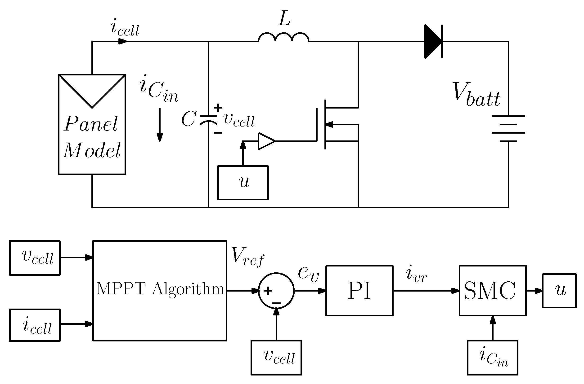
2.1. Power Electronics

Switched converters are the most widely used devices for the efficient management of energy in PV systems. These are composed of a controlled commuted element, which is usually a MOSFET, and a non-controlled element such as a power fast diode. However, in order to transfer power of the input to output with the maximum efficiency possible, diverse control strategies are commonly used for to obtain the control signals that switch the active elements.
The topologies of the switched converters allow us to manipulate the power transfer between its input and output. For the present application, the boost topology [38,39,40] has been chosen. The conversion ratio in a Boost converter is well known in the technical literature. From Equation (3), we can deduce that d is the duty cycle of the MOSFET command signal.
v C 0 = 1 1 d v c e l l
Therefore, to remove the maximum power of a panel, a control strategy is implemented, which handles the duty cycle and always manages to extract the maximum possible power of the panel.
The following subsections describe the implementation of the P&O and PSO algorithms used in the paper for comparison purposes.

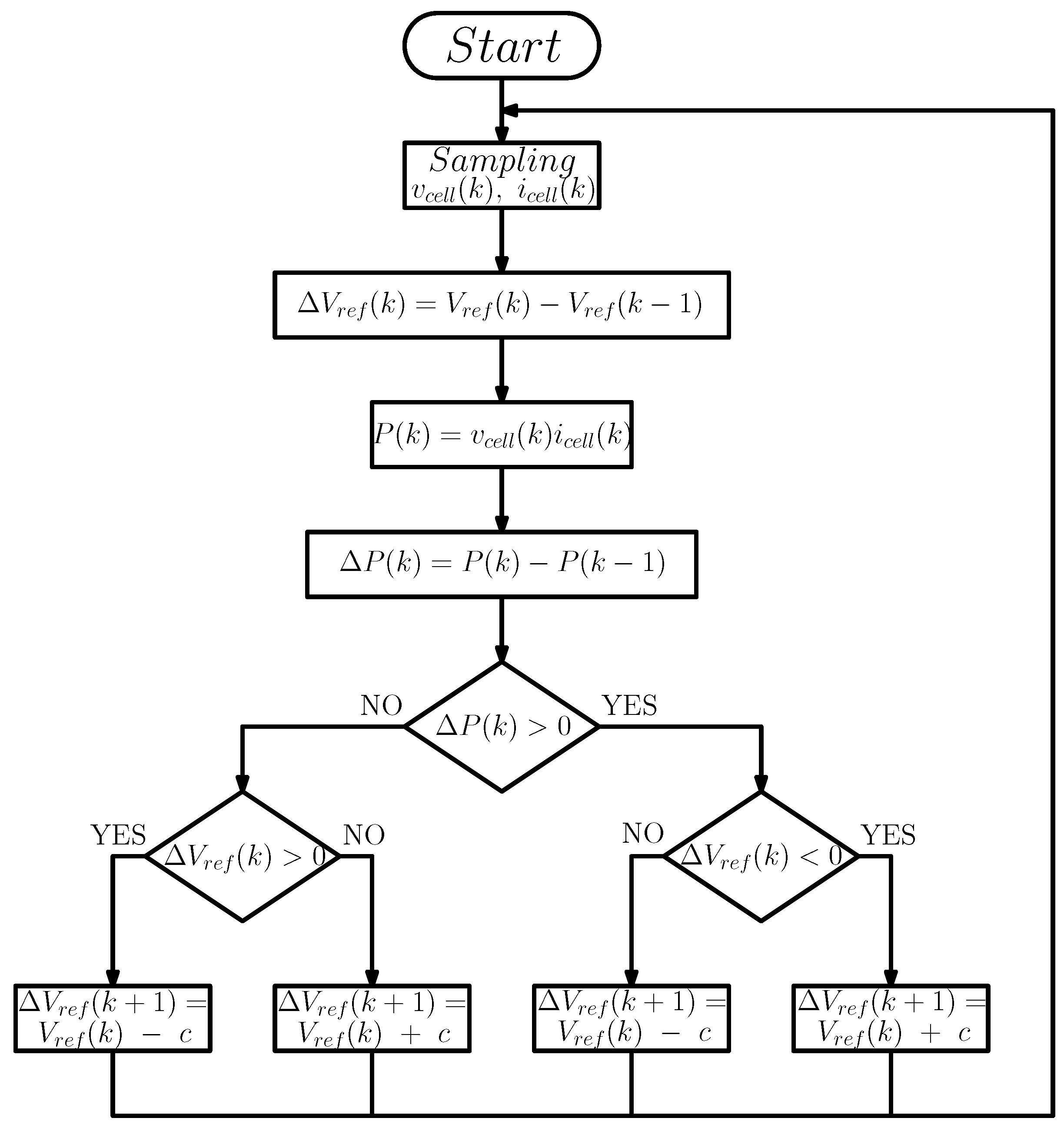
2.2. MPPT Algorithms Based on P&O

The optimization algorithm P&O consists of varying the voltage reference or the converter input current. Afterward, the amount of power converted from the panel is measured. If it is greater than the power measured previously, the voltage reference is steadily increased in the same proportion, and if not it is decremented. These steps are continually taken in order to find the optimum MPPT. The disadvantage of this algorithm is that in some cases, especially under partial shading, the algorithm cannot find the maximum power point. As it is a widely used algorithm, it is a good idea to implement it and take it as a reference point. Figure 2 presents the P&O algorithm and its implementation for the MPPT in PSIM® in Figure 5, [41].
Optimization of system 1 cannot be dealt with by traditional algorithms. In order to find their target, heuristic algorithms have been developed with specific tasks that must resolve a problem intelligently. In the world of renewable energy, optimization algorithms for the MPPT problem are used to improve energy transformation. Among the most used algorithms, we find the P&O, which is used by many authors such as [13,42,43,44]. Its simplicity and few code lines make it easy to deploy.

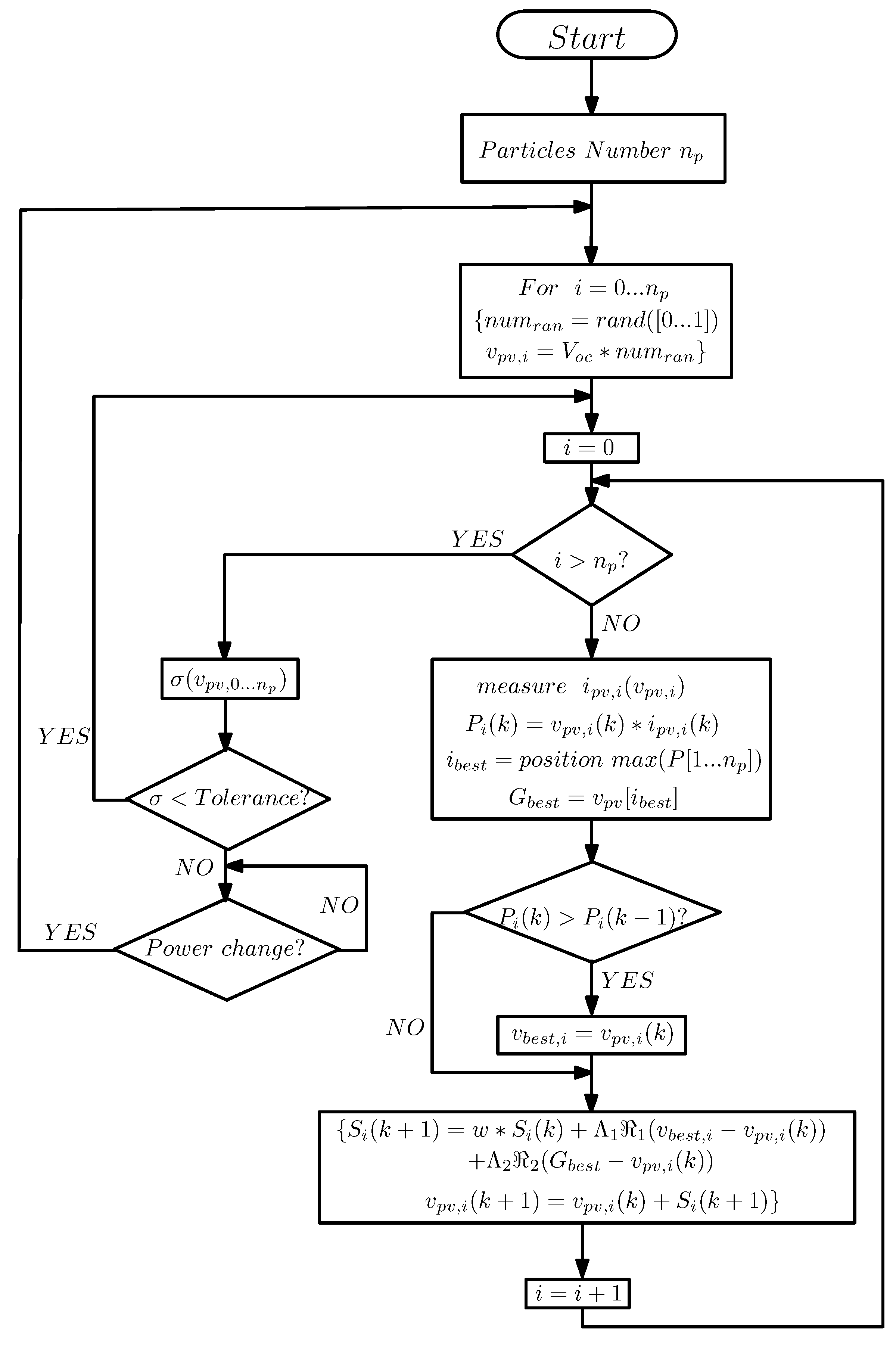
2.3. MPPT Algorithm Based on PSO

The algorithm based on a particles swarm optimization (PSO) [45,46], is a heuristic search method with a population that takes stochastic values, which is inspired by swarms.
The PSO algorithm generates a set of values or random particles and each particle represents a candidate solution. The position of each particle is influenced by a particle in a better position, in our case by the reference voltage value that generates the greatest power conversion. Once the particle with a better position is found, all particles will be influenced by this.
The particle with a better position will eventually be the final output of the algorithm after a predefined number of iterations or by a margin determined previously. However, the convergence to MPP cannot be ensured. Therefore, the stopping condition could be either, or a combination, of these situations, to ensure that there shall not be an endless number of cycles. The algorithm applied to the power conversion of a PV panel is described in Figure 3.

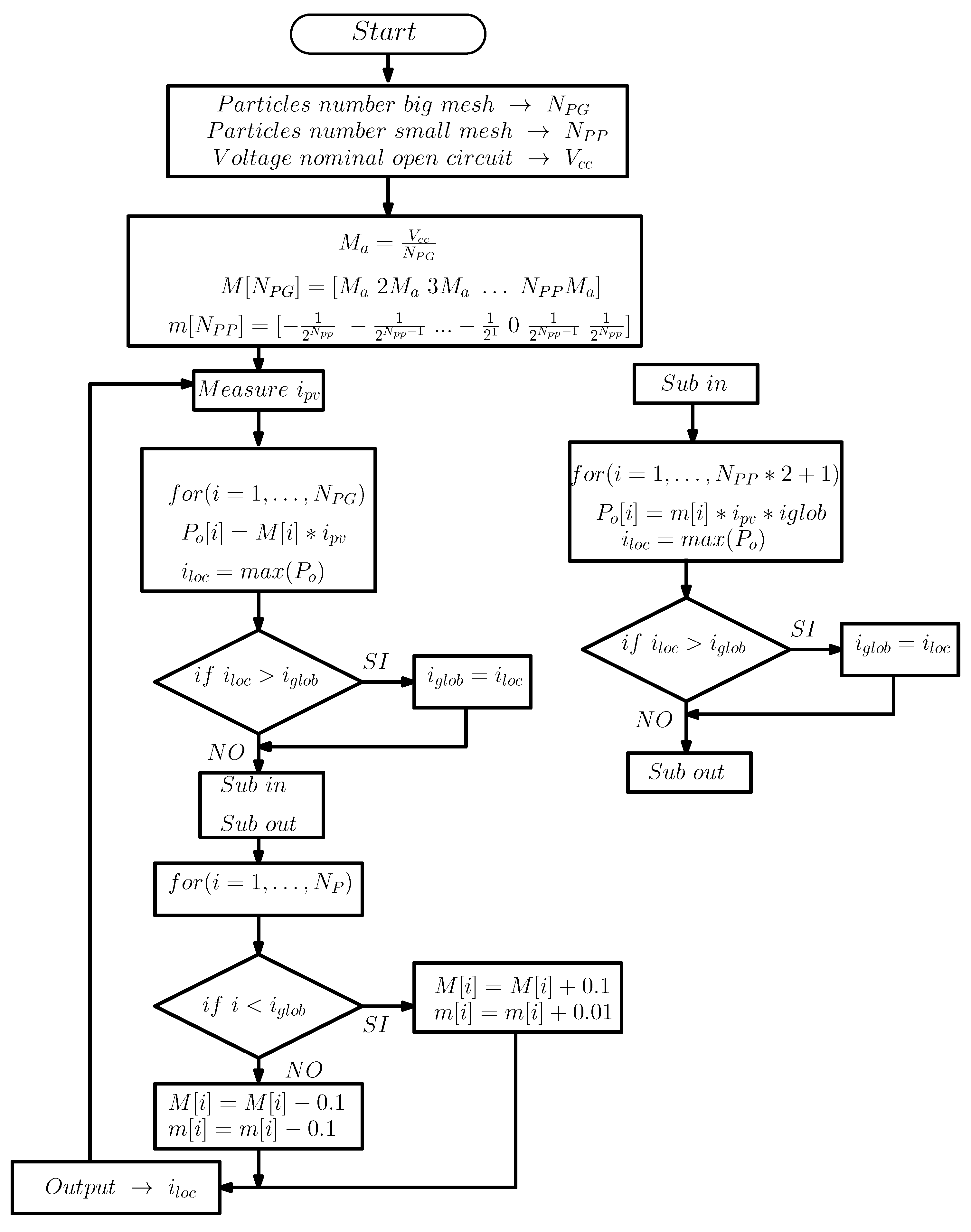
3. MPPT Algorithm Based on IPSM

Pattern search algorithms are conformed by two fundamental parts, a sequence of meshes and a list of polling conditions. A mesh is a lattice to which the search for an iteration is restricted. Along with the optimization, the polling conditions give the guidelines for the refinement of the current mesh, ensuring in this way the convergence of the algorithm to the global minimum.
The optimization algorithm based on IPSM is the evolution of the Pattern Search Method (PSM) algorithm used by [11,47,48]. It is a search method with a finite population forming a mesh with geometric distances between each member. Each element of the mesh represents a candidate solution. The meshes move evenly towards the candidate with the best position, iteration by iteration, until achieving convergence. The presented algorithm implements a modification with respect that proposed in [29]. Thus, the search is additionally performed between adjacent members to the candidate with the best position. This is done in order to assure the converge in all possible cases (radiation or partial shading). The algorithm applied to the power conversion of a photovoltaic panel is described in Figure 4.

3.1. Convergence Results of the IPSM

This section states the convergence results of the algorithm presented in Figure 4, guaranteeing the MPP in all cases. We establish that the proposed algorithm is able to find the global maximum of the proposed approach.
In this case we assume that the problem has a global maximum but there may be local maximum. Thus, the original generalized PSM given in [33] is extended in [49] to functions with multiple local maxima. This has been done making a dense search which can be achieved when Δ μ and Δ m are very close to zero. This implies that at each iteration the updating of the new models does not lose the global maximum, since the new models are very close to old ones. Therefore, we are applying the results from [49], since the MPPT problem has been formulated within an IPSM frame and taking advantage of this technique in its applications to Power Control Theory. Also, note that the results from [49] require Δ μ and Δ m sufficiently close to zero. However, it has been observed in simulation examples, showing some of them in Section 4, that a finite value for it suffices.

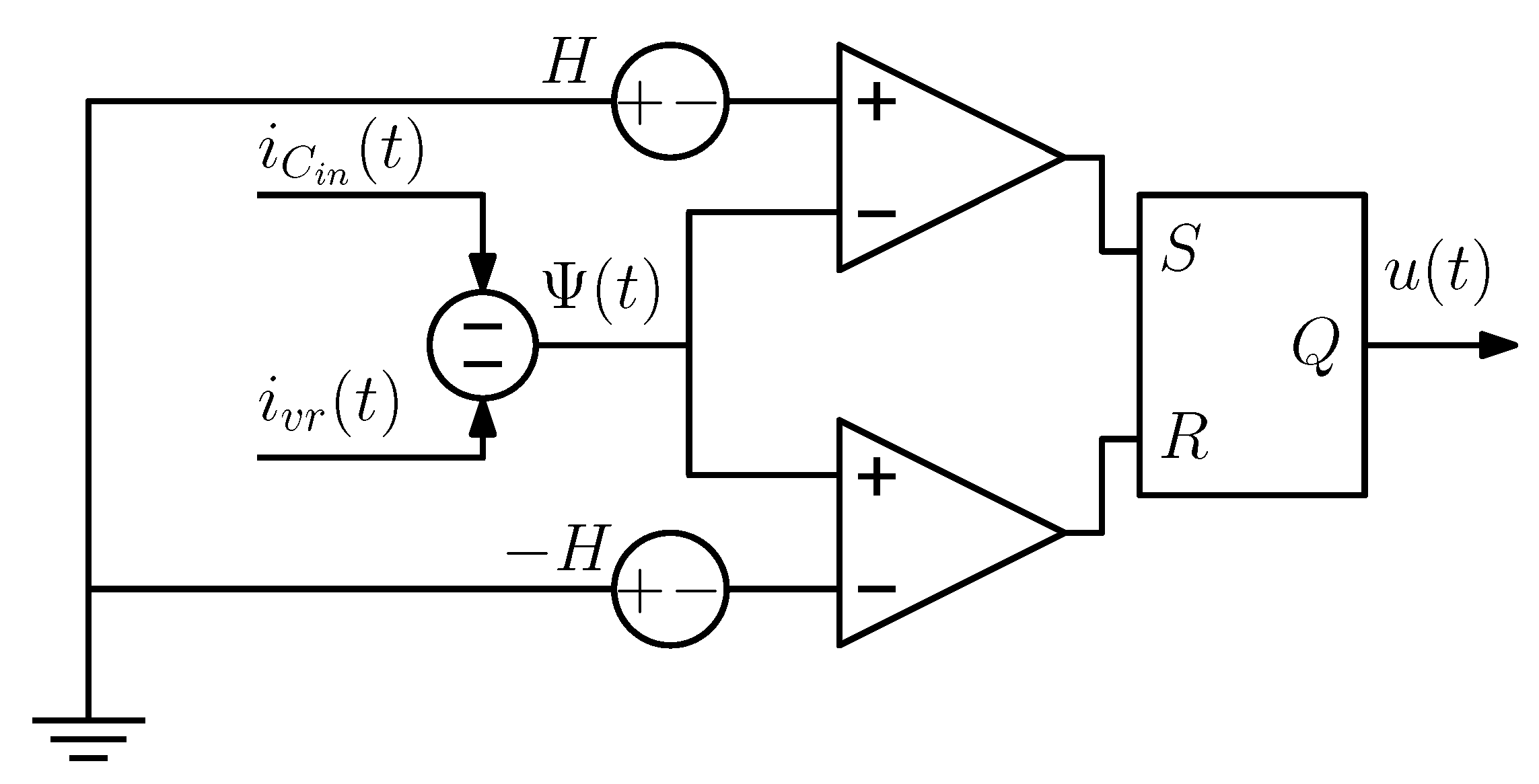
3.2. Sliding Mode Control

The output of the MPPT optimization algorithm is a voltage reference that must be imposed by the switch converter to the PV panel. A controller is in charge of ensuring that the output of the PV panel track be the reference, established by the MPPT optimization algorithm. Usually, PI controllers are used for such a purpose, which are designed based on the linearization of the system (1) around a certain operation point [50]. However, the voltage reference varies considerably with time, a fact that moves the system over its nonlinear behavior [35]. The presence of un-modeled dynamics, along with nonlinear behavior, could degrade closed-loop performance, even causing instability [50].
The sliding mode control is robust and very insensitive to changes in the operation point. However, the existence of a sliding mode control needs three conditions to assure the stability of the sliding surface and success with this control. The three conditions are transversality, reachability, and the equivalent control, and are used to assure the system’s trajectories are around the sliding surface [51]. The sliding surface adopted in this work is based on [34] (see (4)), where the closed-loop stability proof can also be found.
Ψ ( t ) = i C i n ( t ) i v r ( t )
where i v r is the capacitor reference current established by a PI compensator of cell voltage error (see Figure 5). PI is given by:
P I ( s ) = k p + k i s
The block diagram of the sliding surface and the control law implementation, u, from a hysteresis function are presented in Figure 6.
According to [34], the relationship of the constants of the PI controller, k p and k i , are given in (6).
k p = 2 · C i n · ξ · w n k i = C i n · w n 2
where ξ is the damping constant and w n is the natural frequency of oscillation. Design criteria for k p and k i are given by a switching frequency minimal f s w , a settling time t s , and a damping ξ .

4. Results

Table 1 shows the simulation parameters used in PSIM. In this sense, we use the physical model of a PV panel according to the renewable energy module of PSIM [52], with parameters corresponding to MSX-60 [53] and relationship coefficient of 0.015 °C · m 2 / W. This means that for an environment temperature of 25 °C, the PV panel will operate to 40 °C if irradiance is 1000 W / m 2 and 32.5 °C if irradiance is 500 W / m 2 . In the boost converter, the input capacitance is equal to 22 μ F, the inductance is 100 μ H, and an inductor current ripple of Δ i L = 1 A. Due to SMC, the converter switches to a variable frequency centered around approximately 49.2 kHz [34]. The system has two controllers; the PI controller designed for t s = T a / 2 = 200 μ s and a damping of 0.7, with proportional constant and integration time of 0.861 and 50 μ s, respectively; and SMC with hysteresis band, according to Δ i L = 1 A of 0.5 A. Moreover, all the MPPT algorithms have a perturbation period of 400 μ s, while the perturbation amplitude is 1 V for the P&O algorithm and the initial perturbation amplitudes are 0.2 V and 0.8 V for the IPSM algorithms, with 40 and 10 particles, respectively. Finally, voltage reference for PI controller is filter with a cut-off frequency of 20 kHz.
The system is perturbed with an irradiance step of 1000 W / m 2 in the instant 0 and after 50 ms the irradiance is decreased by 50 % .

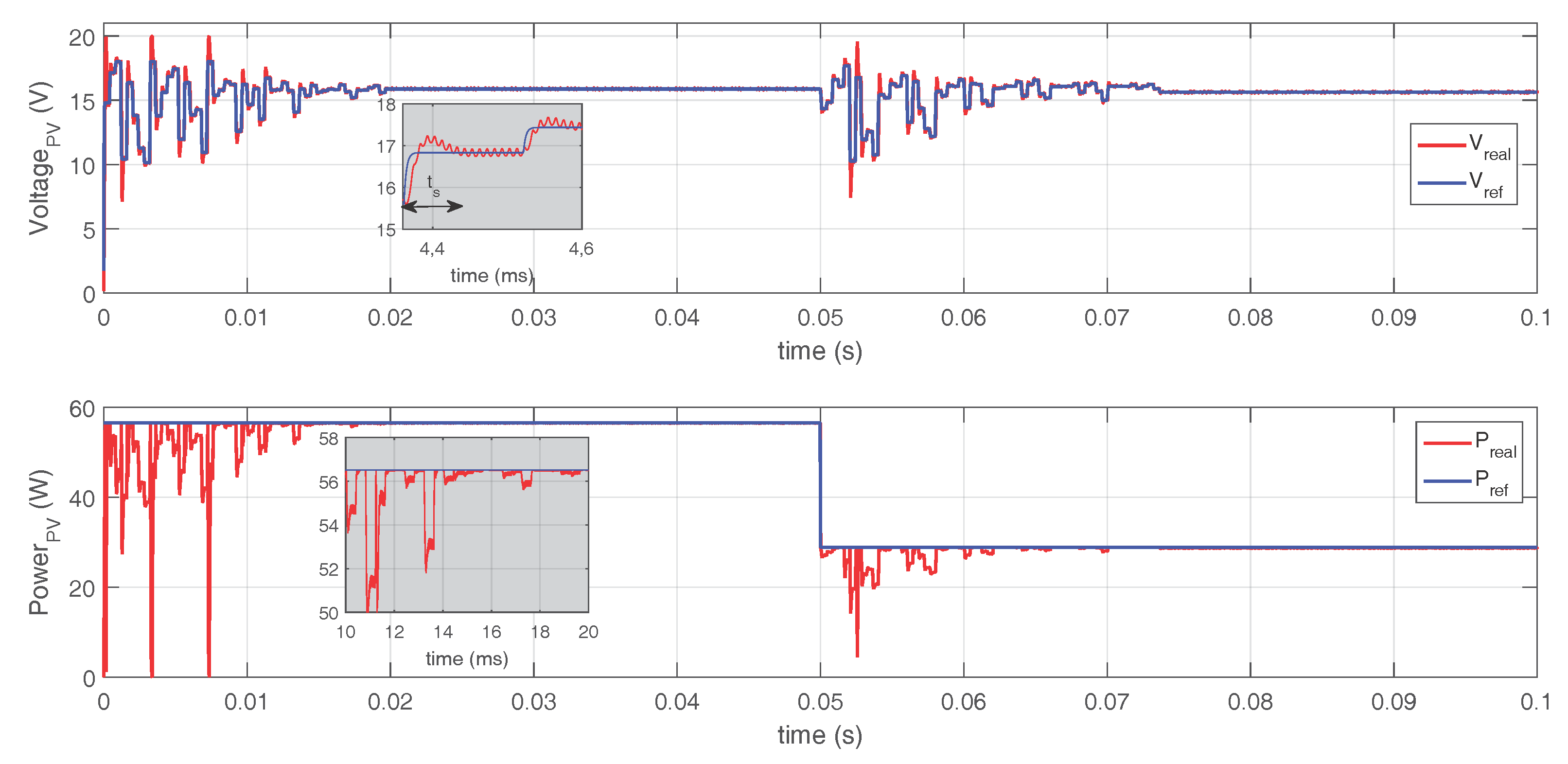
4.1. Response Using P&O

The behavior of MPPT based on P&O is widely known. In this paper, simulations of MPPT were generated, based on P&O with perturbation amplitudes of 0.25 V, 0.5 V, 0.75 V, and 1.5 V, besides 1 V. Figure 7 shows the performance of the P&O algorithm with a perturbation amplitude of 1 V. The time to reach the maximum power point is close to 4.4 ms, while the steady-state error is 1.6% and energy losses during 100 ms are 143 mJ. The zoom of the voltage sub-figure shows the settling time designed with the PI controller, 200 μ s, and the perturbation amplitude of the P&O, 1 V.
Table 2 shows that the greater the perturbation amplitude, the greater the energy losses and the error MPP of the steady-state. On the other hand, the settling time will decrease.

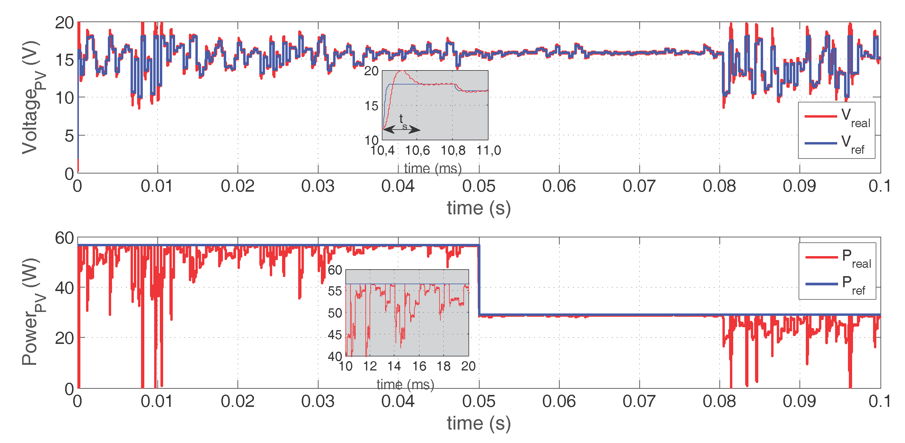
4.2. Response Using PSO

The MPPT response with PSO (algorithm Figure 3) can be seen in Figure 8 and Figure 9. Since the PSO algorithm does not guarantee the location of the optimal solution, 10 simulations with 10 particles were made, and 10 simulations with 40 particles.
PSO with 10 particles shows an average settling time of 22.7 ms, an average MPP steady-state error of 0.11 % , and average energy losses of 96.98 mJ (see Table 3). In each simulation, the algorithm reached the MPP before the simulation ended. (see Figure 8). The performance of the PI controller is according to the design criterion.
On the other hand, the PSO algorithm with 40 particles, during the simulation time (50 ms between perturbations), never reached the steady-state and it was always moving particles around the search-space (see Figure 9). For this reason, it is not possible to obtain a quantification of settling time or error MPP of steady-state. On average, the energy losses were of 246.8 mJ (see Table 3).

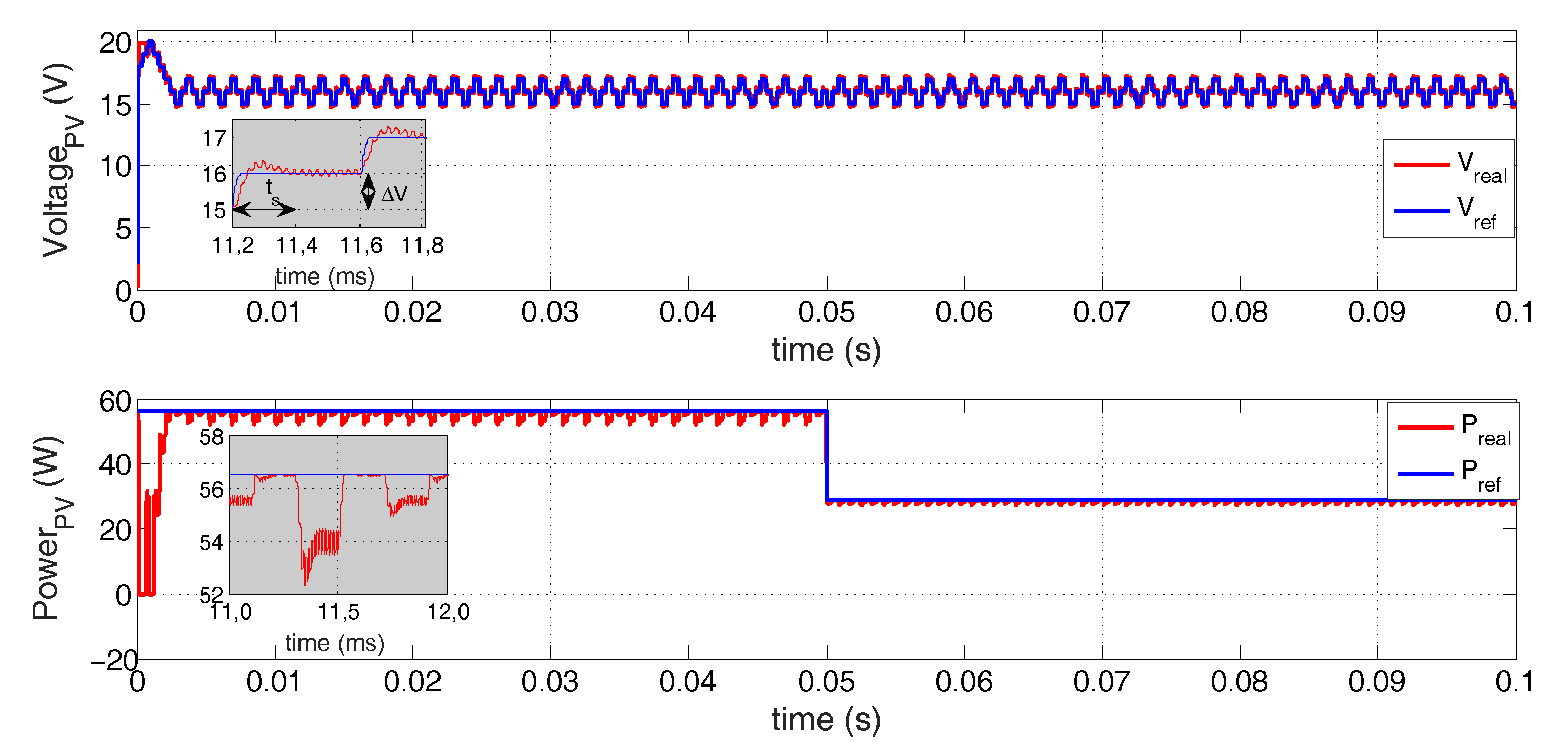
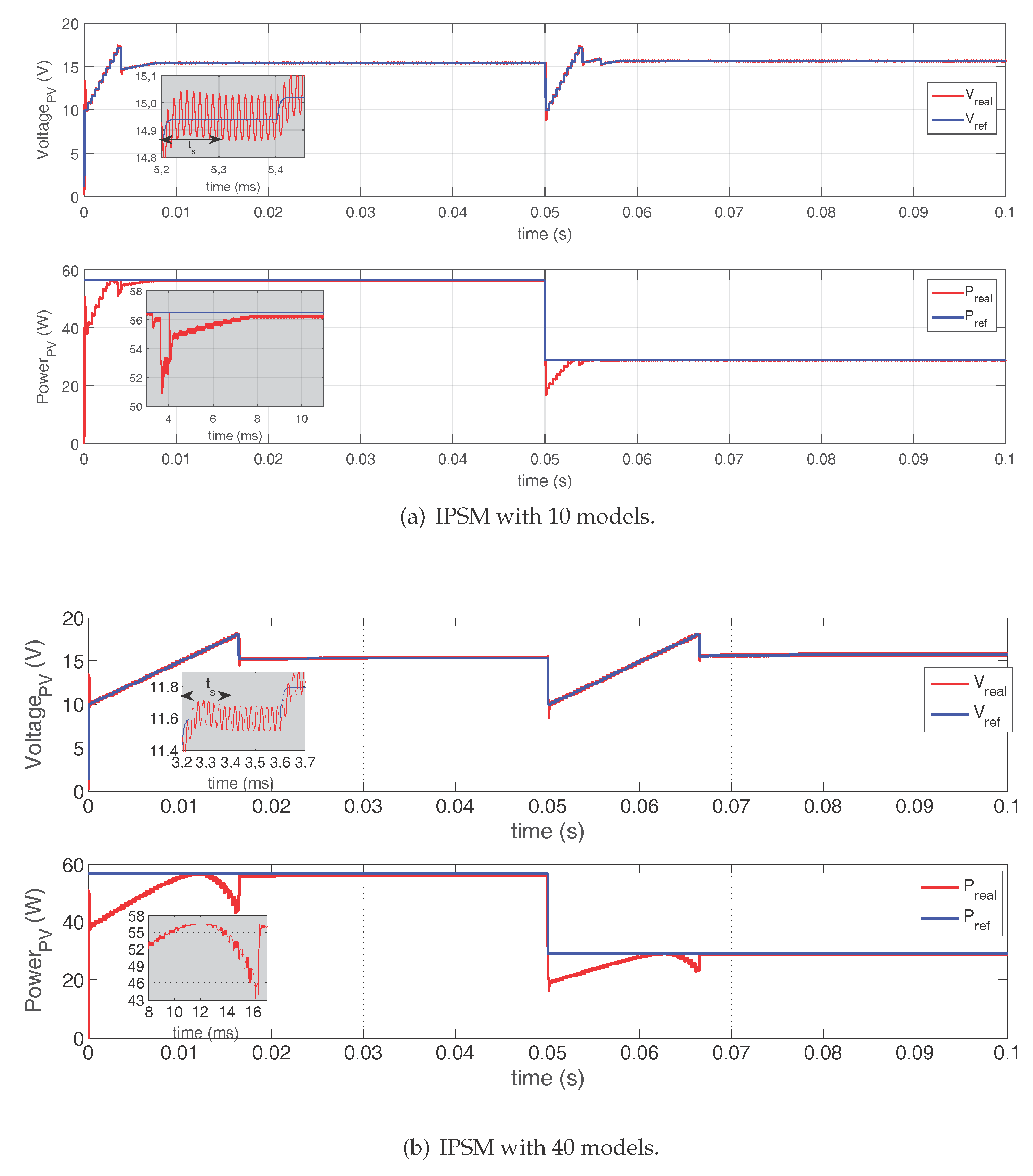
4.3. Response Using IPSM

A similar experiment to that presented in the Section 4.2 is carried out but, in this case, using MPPT based on IPSM (algorithm Figure 4) with 10 and 40 models, see Figure 10a,b, respectively. In this optimization method, which is easy to implement and computationally efficient, the approximation ramp to the best solution can be observed. First, with large steps and when it is near to the optimal, the algorithm uses small steps. IPSM with 10 models (see Figure 10a) converge faster than IPSM with 40 models (see Figure 10b). This is due to the amplitude of the perturbation depending on the number of models; when the number of models is low, the amplitude of perturbation is greater, causing it to arrive quickly to optimal solution. Later, with smaller steps around the optimal point, obtained previously, the algorithm starts a new search, making 10 or 40 steps, depending of the number of models. Finally, the algorithm ends the search when the difference between the previous power and the current power is lower than 3 % of the maximum power. The algorithm starts a new search if along of the operation detects a power change (>3%).
A summary of the behavior of the algorithm can be seen in Table 4. For the case of 10 models, the settling time is very close to that obtained with the algorithm based on P&O (algorithm Figure 2), while for the case of 40 models the settling time is greater than that of the PSO algorithm (Figure 3) with 10 particles. In the same way, the error in steady-state is greater for the case of IPSM with 10 models, since the size of perturbation depends on the number of models. However, due to this algorithm getting closer to the MPP, the IPSM with 10 models generates less energy losses that the IPSM with 40 models.

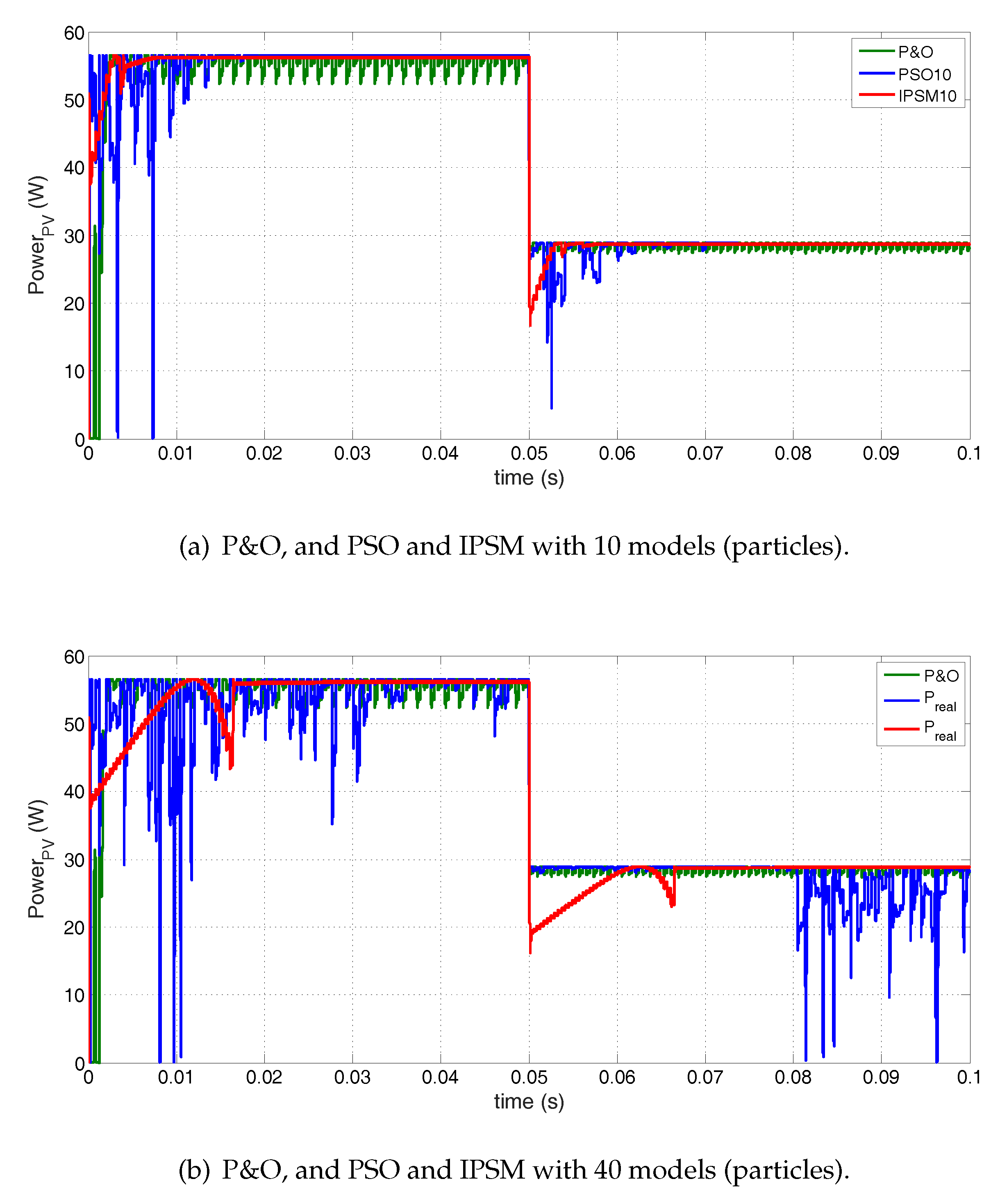
4.4. Comparative Analysis of MPPT Algorithms

In Table 2, Table 3 and Table 4 it is possible to deduct that the P&O algorithm is the fastest one to obtain the MPP, but its constant oscillation around the MPP generates considerable energy losses to the system, which are very important in long time periods. In the case of IPSM for 10 models (see Figure 11a), the oscillation around the MPP is stopped quickly, since the variation of the power is lower than 3 % . Besides, the PSO for 10 particles is slower to obtain the MPP and it presents great oscillations at the beginning of the search.
The energy losses with P&O along to disturbance length decreases, making this algorithm slower to obtain the MPP. For the case of the PSO with 40 models (see Figure 11b), this algorithm cannot obtain the steady-state and presents the greatest energy losses of all, due to permanent oscillation. In contrast with the IPSM algorithm, which takes longer to arrive to the MPP but guarantees the MPP in all cases.

5. Conclusions

In the present work, we compared three optimization algorithms, namely, P&O, PSO, and IPSM, for MPPT. We described each one of the algorithms, we used the SMC and we simulated all of them in PSIM®. In the simulation, different number of models (particles) were taken into account. The figures display the results produced by each of the tests.
From the simulation results, we conclude that the P&O algorithm is the fastest one to obtain the MPP, but its constant oscillation around the MPP generates considerable energy losses to the system. The PSO algorithm presents great oscillations, the greatest energy losses, and in some cases it cannot obtain the MPP. Besides, the IPSM algorithm is slower to obtain the MPP but presents lower energy losses in comparison with the other two algorithms. Additionally, the convergence to the maximum power point can only be ensured by the proposed IPSM algorithm, which is the main advantage with respect the other approaches (P&O and PSO).
We highlight that the IPSM is the algorithm recommended for the implementation in real systems, since this algorithm presents lower energy losses versus adequate settling time, as well as a soft behavior, which is recommended to extend the useful life of the power electronics.

Acknowledgments

This work was supported by the Instituto Tecnológico Metropolitano (ITM) of Medellin, Colombia through grant P14105, by the thesis master “Metodología para optimizar el seguimiento del punto de potencia máximo de un generador de celdas fotovoltaicos usando técnicas de control multi-modelo” code PM-14101 and the project P14220, and A. Ibeas is partially supported by the Spanish Ministry of Economy and Competitiveness through grant DPI2016-77271-R and by the University of the Basque Country (UPV/EHU) through grant PPG17/33.

Author Contributions

All the authors contributed equally to the work.

Conflicts of Interest

The authors declare no conflict of interest.

References

  1. Karami, N.; Moubayed, N.; Outbib, R. General review and classification of different {MPPT} Techniques. Renew. Sustain. Energy Rev. 2017, 68, 1–18. [Google Scholar] [CrossRef]
  2. Masoum, M.A.S.; Dehbonei, H.; Fuchs, E.F. Theoretical and experimental analyses of photovoltaic systems with voltage- and current-based maximum power-point tracking. IEEE Trans. Energy Convers. 2002, 17, 514–522. [Google Scholar] [CrossRef]
  3. Schoeman, J.J.; Wyk, J.D. A simplified maximal power controller for terrestrial photovoltaic panel arrays. In Proceedings of the Power Electronics Specialists Conference, Cambridge, MA, USA, 14–17 June 1982; pp. 361–367. [Google Scholar]
  4. Yamashita, H.; Tamahashi, K.; Michihira, M.; Tsuyoshi, A.; Amako, K.; Park, M. A novel simulation technique of the PV generation system using real weather conditions. In Proceedings of the Power Conversion Conference, Osaka, Japan, 2–5 April 2002; Volume 2, pp. 839–844. [Google Scholar]
  5. Pan, C.T.; Chen, J.Y.; Chu, C.P.; Huang, Y.S. A fast maximum power point tracker for photovoltaic power systems. In Proceedings of the 25th Annual Conference of the IEEE Industrial Electronics Society, San Jose, CA, USA, 29 November–3 December 1999; pp. 390–393. [Google Scholar]
  6. Mulmule, A.; Vatti, R.; Porwal, P. MPPT Technique to improve efficiency in wind-solar hybrid system. Int. J. Electr. Eng. Technol. 2013, 4, 74–82. [Google Scholar]
  7. Femia, N.; Petrone, G.; Spagnuolo, G.; Vitelli, M. Optimization of perturb and observe maximum power point tracking method. IEEE Trans. Power Electron. 2005, 20, 963–973. [Google Scholar] [CrossRef]
  8. Piegari, L.; Rizzo, R. Adaptive perturb and observe algorithm for photovoltaic maximum power point tracking. IET Renew. Power Gener. 2010, 4, 317–328. [Google Scholar] [CrossRef]
  9. Kazan, F.; Karaki, S.; Jabr, R.; Mansour, M. Maximum power point tracking using ripple correlation and incremental conductance. In Proceedings of the 47th International Universities Power Engineering Conference (UPEC), London, UK, 4–7 September 2012; pp. 1–6. [Google Scholar]
  10. Kish, G.; Lee, J.; Lehn, P. Modelling and control of photovoltaic panels utilising the incremental conductance method for maximum power point tracking. IET Renew. Power Gener. 2012, 6, 259. [Google Scholar] [CrossRef]
  11. Messalti, S.; Harrag, A.; Loukriz, A. A new variable step size neural networks {MPPT} controller: Review, simulation and hardware implementation. Renew. Sustain. Energy Rev. 2017, 68, 221–233. [Google Scholar] [CrossRef]
  12. Bahgat, A.; Helwa, N.; Ahmad, G.; Shenawy, E.E. Maximum power point traking controller for {PV} systems using neural networks. Renew. Energy 2005, 30, 1257–1268. [Google Scholar] [CrossRef]
  13. Kang, S.; Ko, J.; Choi, J.; Jang, M.; Mun, J.; Lee, J.; Chung, D. A Novel MPPT Control of photovoltaic system using FLC algorithm. In Proceedings of the 2011 11th International Conference on Control, Automation and Systems (ICCAS), Gyeonggi-do, Korea, 26–29 October 2011; pp. 434–439. [Google Scholar]
  14. Liu, Y.H.; Liu, C.L.; Huang, J.W.; Chen, J.H. Neural-network-based maximum power point tracking methods for photovoltaic systems operating under fast changing environments. Solar Energy 2013, 89, 42–53. [Google Scholar] [CrossRef]
  15. Mellit, A.; Kalogirou, S.A. MPPT-based artificial intelligence techniques for photovoltaic systems and its implementation into field programmable gate array chips: Review of current status and future perspectives. Energy 2014, 70, 1–21. [Google Scholar] [CrossRef]
  16. Veerachary, M.; Yadaiah, N. ANN based peak power tracking for PV supplied DC motors. Solar Energy 2000, 69, 343–350. [Google Scholar] [CrossRef]
  17. Adly, M.; Besheer, A. A meta-heuristics search algorithm as a solution for energy transfer maximization in stand-alone photovoltaic systems. Int. J. Electr. Power Energy Syst. 2013, 51, 243–254. [Google Scholar] [CrossRef]
  18. Chiu, C. T-S Fuzzy Maximum Power Point Tracking Control of Solar Power Generation Systems. IEEE Trans. Energy Convers. 2010, 25, 1123–1132. [Google Scholar] [CrossRef]
  19. Larbes, C.; Cheikh, S.A.; Obeidi, T.; Zerguerras, A. Genetic algorithms optimized fuzzy logic control for the maximum power point tracking in photovoltaic system. Renew. Energy 2009, 34, 2093–2100. [Google Scholar] [CrossRef]
  20. Liu, C.L.; Chen, J.H.; Liu, Y.H.; Yang, Z.Z. An Asymmetrical Fuzzy-Logic-Control-Based MPPT Algorithm for Photovoltaic Systems. Energies 2014, 7, 2177–2193. [Google Scholar] [CrossRef]
  21. Salah, C.B.; Ouali, M. Comparison of fuzzy logic and neural network in maximum power point tracker for {PV} systems. Electr. Power Syst. Res. 2011, 81, 43–50. [Google Scholar] [CrossRef]
  22. Chowdhury, S.R.; Saha, H. Maximum power point tracking of partially shaded solar photovoltaic arrays. Solar Energy Mater. Solar Cells 2010, 94, 1441–1447. [Google Scholar] [CrossRef]
  23. Esram, T.; Chapman, P.L. Comparison of photovoltaic array maximum power point tracking techniques. IEEE Trans. Energy Convers. 2007, 22, 439–449. [Google Scholar] [CrossRef]
  24. Amine, H.M.; Abdelaziz, H.; Najib, E. Maximum Power Point Tracking Using IT2FL Tuned with GA. Energy Procedia 2015, 83, 399–407. [Google Scholar] [CrossRef]
  25. Zhao, J.; Zhou, X.; Gao, Z.; Ma, Y.; Qin, Z. A novel global maximum power point tracking strategy (GMPPT) based on optimal current control for photovoltaic systems adaptive to variable environmental and partial shading conditions. Solar Energy 2017, 144, 767–779. [Google Scholar] [CrossRef]
  26. Das, N.; Wongsodihardjo, H.; Islam, S. Modeling of multi-junction photovoltaic cell using MATLAB/ Simulink to improve the conversion efficiency. Renew. Energy 2015, 74, 917–924. [Google Scholar] [CrossRef]
  27. Jouda, A.; Elyes, F.; Rabhi, A.; Abdelkader, M. Optimization of Scaling Factors of Fuzzy—MPPT Controller for Stand-alone Photovoltaic System by Particle Swarm Optimization. Energy Procedia 2017, 111, 954–963. [Google Scholar] [CrossRef]
  28. Soufi, Y.; Bechouat, M.; Kahla, S. Fuzzy-PSO controller design for maximum power point tracking in photovoltaic system. Int. J. Hydrog. Energy 2017, 42, 8680–8688. [Google Scholar] [CrossRef]
  29. Yaqoob-Javed, M.; Faisal-Murtaza, A.; Ling, Q.; Qamar, S.; Majid-Gulzar, A. A novel MPPT design using generalized pattern search for partial shading. Energy Build. 2016, 133, 59–69. [Google Scholar] [CrossRef]
  30. Audet, C. Convergence results for generalized pattern search algorithms are tight. Optim. Eng. 2004, 5, 101–122. [Google Scholar] [CrossRef]
  31. Herrera, J.; Ibeas, A.; Alcántara, S.; de la Sen, M.; Serna, S. Identification and control of delayed SISO systems through pattern search methods. J. Frankl. Inst. 2013, 350, 3128–3148. [Google Scholar] [CrossRef]
  32. Herrera, J.; Ibeas, A.; de la Sen, M. Identification and control of integrative MIMO systems using pattern search algorithms: An application to irrigation channels. Eng. Appl. Artif. Intell. 2013, 26, 334–346. [Google Scholar] [CrossRef]
  33. Booker, A.J.; Dennis, J.J.E.; Frank, P.D.; Serafini, D.B.; Torczon, V.; Trosset, M.W. A rigorous framework for optimization of expensive functions by surrogates. Struct. Optim. 1999, 17, 1–13. [Google Scholar] [CrossRef]
  34. Bianconi, E.; Calvente, J.; Giral, R.; Mamarelis, E.; Petrone, G.; Ramos-Paja, C.A.; Spagnuolo, G.; Vitelli, M. A Fast Current-Based MPPT Technique Employing Sliding Mode Control. IEEE Trans. Ind. Electron. 2013, 60, 1168–1178. [Google Scholar] [CrossRef]
  35. Petrone, G.; Ramos-Paja, C.; Spagnuolo, G. Photovoltaic Sources Modeling; Wiley-IEEE: Hoboken, NJ, USA, 2017. [Google Scholar]
  36. Attivissimo, F.; Nisio, A.D.; Savino, M.; Spadavecchia, M. Uncertainty Analysis in Photovoltaic Cell Parameter Estimation. IEEE Trans. Instrum. Meas. 2012, 61, 1334–1342. [Google Scholar] [CrossRef]
  37. Ahmad, T.; Sobhan, S.; Nayan, M.F. Comparative Analysis between Single Diode and Double Diode Model of PV Cell: Concentrate Different Parameters Effect on Its Efficiency. J. Power Energy Eng. 2016, 4, 31–46. [Google Scholar] [CrossRef]
  38. Cuk, S.; Middlebrook, R. Advances in Switched-Mode Power Conversion Part I. IEEE Trans. Ind. Electron. 1983, 1, 10–19. [Google Scholar] [CrossRef]
  39. Middlebrook, R. Modeling current-programmed buck and boost regulators. IEEE Trans. Power Electron. 1989, 4, 36–52. [Google Scholar] [CrossRef]
  40. Wester, G.; Middlebrook, R.; Member, S. Low-Frequency Characterization of Switched dc-dc Converters. IEEE Trans. Aerosp. Electron. Syst. 1973, 3, 376–385. [Google Scholar] [CrossRef]
  41. Hussein, K.; Muta, I.; Hshino, T.; Osakada, M. Maximum photovoltaic power tracking: An algorithm for rapidly changing atmospheric conditions. Proc. Inst. Elect. Eng. 1995, 142, 59–64. [Google Scholar] [CrossRef]
  42. Liu, Y.; Li, M.; Ji, X.; Luo, X.; Wang, M.; Zhang, Y. A comparative study of the maximum power point tracking methods for PV systems. Energy Convers. Manag. 2014, 85, 809–816. [Google Scholar] [CrossRef]
  43. Nedumgatt, J.; Jayakrishnan, K.; Umashankar, S.; Vijayakumar, D. Perturb and Observe MPPT Algorithm for Solar PV Systems-Modeling and Simulation. In Proceedings of the 2011 Annual IEEE India Conference (INDICON), Hyderabad, India, 16–18 December 2011. [Google Scholar]
  44. Sridhar, R.; Selvan, N.T.; Jeevananthan, S.; Chowdary, P.S. Performance Improvement of a Photo Voltaic Array Using MPPT (P&O) Technique. In Proceedings of the 2010 IEEE International Conference on Communication Control and Computing Technologies (ICCCCT), Ramanathapuram, India, 7–9 October 2010; pp. 191–195. [Google Scholar]
  45. Salam, Z.; Ahmed, J.; Merugu, B. The application of soft computing methods for MPPT of PV system: A technological and status review. Appl. Energy 2013, 107, 135–148. [Google Scholar] [CrossRef]
  46. Soon, J.; Low, K.; Member, S. Photovoltaic Model Identification Using Particle Swarm Optimization with Inverse Barrier Constraint. IEEE Trans. Power Electron. 2012, 27, 3975–3983. [Google Scholar] [CrossRef]
  47. Herrera, J.; Ibeas, A.; De La Sen, M.; Rivera, E.; Peláez, J. Generalized Pattern Search Methods for control of stable, unstable and integrating systems with unknown delay under step input. Math. Comput. Simul. 2015, 115, 37–48. [Google Scholar] [CrossRef]
  48. Herrera, J.; Ibeas, A.; Alcántara, S. Identification and adaptive control of delayed unstable systems. In Proceedings of the 2010 IEEE International Symposium on Intelligent Control (ISIC), Yokohama, Japan, 8–10 September 2010; pp. 767–772. [Google Scholar]
  49. Audet, C.; Dennis, J.J.E. Mesh adaptive direct search algorithms for constrained optimization. SIAM J. Optim. 2006, 17, 188–217. [Google Scholar] [CrossRef]
  50. Trentelman, H.; Stoorvogel, A.A.; Hautus, M. Control Theory for Linear Systems; Springer Science & Business Media: Berlin, Germany, 2012. [Google Scholar]
  51. Serna-Garcés, S.; Gonzalez Montoya, D.; Ramos-Paja, C. Sliding-Mode Control of a Charger/Discharger DC/DC Converter for DC-Bus Regulation in Renewable Power Systems. Energies 2016, 9, 245. [Google Scholar] [CrossRef]
  52. PSIM Tutorial: How to Use Solar Module Physical Model. Powersim Inc. Available online: https://powersimtech.com/drive/uploads/2016/04/Tutorial-Solar-Module-physical-model.pdf (accessed on 24 August 2017).
  53. MSX-60 and MSX-64 Photovoltaic Modules; Solarex: Frederick, MD, USA, 1997.
Figure 1. Circuital schemes of the single-diode model for representing PV panels.
Energies 10 01316 g001
Figure 2. P&O algorithm.
Energies 10 01316 g002
Figure 3. PSO algorithm.
Energies 10 01316 g003
Figure 4. IPSM algorithm.
Energies 10 01316 g004
Figure 5. General Scheme of the MPPT controller.
Energies 10 01316 g005
Figure 6. Sliding surface and control law of the SMC.
Energies 10 01316 g006
Figure 7. MPPT based on P& O. Profile of the PV panel voltage and power extraction.
Energies 10 01316 g007
Figure 8. MPPT based in PSO with 10 particles. Profile of the PV panel voltage and power extraction.
Energies 10 01316 g008
Figure 9. MPPT based in PSO with 40 particles. Profile of the PV panel voltage and power extraction.
Energies 10 01316 g009
Figure 10. MPPT based in IPSM. Profile of the PV panel voltage and power extraction.
Energies 10 01316 g010
Figure 11. Comparison of MPPT algorithms. Profile of power extraction.
Energies 10 01316 g011
Table 1. Simulation Parameters.
Panel MSX-60Boost ConverterControllersMPPT
I s c = 3.8 A
V o c = 21.1 V
I m p = 3.5 A
V m p = 17.1 V
I s 1 = I s 2 = 4.704 × 10 10
I p v = 3.8 A
R s h = 176.4 Ω
R s = 0.35 ω.
C = 22 μF
L = 100 μH
V o = 24 V
f s w 0 = 49.2 kHz
K p = 0.861
τ i = 50 μs
| H | = 0.5 A
T a = 400 μs
Δ V = 1 V (P& O)
Δ V 0 = 0.2 V (40 p.)
Δ V 0 = 0.8 V (10 p.)
LPF@20 kHz
Table 2. Performance of the MPPT algorithm based in P&O.
Δ V ( V ) t s ( ms ) Error MPP Energy Losses ( mJ )
0.258.80.14%63.1
0.505.20.44%77.4
0.754.91.18%111.0
1.004.41.59%143.1
1.503.26.02%301.8
Table 3. Performance MPPT algorithm based in PSO with 10 and 40 particles.
PSO 10 P.PSO 40 P.
Simulationts (ms)Error MPPEnergy Losses (mJ)Energy Losses (mJ)
126.40.05%108.3233.7
220.40.03%80.7216.4
330.40.25%119.1249.8
424.40.03%132.1239.5
518.40.05%76.2263.2
618.40.03%70.1250.0
718.40.20%89.8229.0
824.40.03%87.6340.5
923.40.06%90.7211.9
1022.40.39%115.2234.0
Average22.700.11%96.98246.80
Table 4. Performance MPPT algorithm based in IPSM with 10 and 40 models.
Models t s ( ms ) Error MPP Energy Losses ( mJ )
107.60.64%70.8
4032.00.50%189.9

