Design Improvisation for Reduced Harmonic Distortion in a Flux Pump-Integrated HTS Generator
by
 ,
,
Ravichandra Kulkarni
1,*, 
Krishnamachar Prasad
1,
Tek Tjing Lie
1,
Rodney A. Badcock
2,
Chris W. Bumby
2 and
Hae-Jin Sung
2 1
Department of Electrical and Electronic Engineering, Auckland University of Technology, Auckland 1010, New Zealand
2
Robinson Research Institute, Victoria University of Wellington, Wellington 5010, New Zealand
*
Author to whom correspondence should be addressed.
Energies 2017, 10(9), 1344; https://doi.org/10.3390/en10091344
Submission received: 29 May 2017
/
Revised: 19 July 2017
/
Accepted: 22 August 2017
/
Published: 6 September 2017
(This article belongs to the Section F: Electrical Engineering)
Abstract
:This paper presents a design improvisation of a flux pump-integrated 10 kW high-temperature superconducting (HTS) proof of concept generator for reduced harmonic distortion. To carry out the design improvisation, a finite element analysis (FEA) model of the 10 kW HTS generator is developed, and time-stepped magnetic transient simulations are conducted on the 2D model. The effects of stator yoke material, winding pitch factors, and load configurations on total harmonic distortion (THD) are investigated. The results showed that fibre-reinforced polymer (FRP) epoxy (G10) can be used as the stator yoke material to effectively avoid the hysteresis and eddy current losses. In addition, the study results show that for the non-conventional design of the machine, a winding pitch of 2/3 and the armature-load configuration of Star-Delta gives THD values within the standard limit defined by IEEE Standard 519-2014. The THD values indicate that the machine design configuration is suitable for the development of machines for both stand-alone and grid-connected operations, according to IEEE STD 519-2014.
1. Introduction
The success of an electromechanical design modelling is in its ability to predict the performance of the system accurately. The penetration of computation software in pre-determining the outcome of the design has become incredibly large. The finite element analysis (FEA) is one such computational method that can be applied to the complex design problems, and maximum improvisation can be carried out before the field test deployment. In this paper, FEA-based simulations on a flux pump-integrated 10 kW high-temperature superconducting (HTS) generator are conducted to analyse the harmonic contents under different operating conditions. Though 10 kW is a low-end rating for a HTS-based machine, it is developed as a proof-of-concept system.
Technologies to deliver higher power wind turbines are sought for efficient renewable generation. Higher power density machines are one solution. High current densities of 106−108 A/mm2 and high magnetic field capabilities of 4−5 T of the second-generation (2G) HTS (Yttrium Barium Copper Oxide-YBCO) materials make them attractive for power-dense electric machine applications [1,2,3]. HTS-based generators are being designed and developed to meet this power demand [4,5,6]. In the design of HTS machines, thermal loss considerations are key to minimising cryogenic load and the local instability of the HTS winding. One way of reducing thermal losses is to minimise the components causing thermal loading on the cryogenic system [7,8]. The use of flux pump avoids the thermal link between the cryogenic and non-cryogenic environments [8,9,10].
The use of flux pumps to excite HTS coils for various applications has come a long way and evolved significantly. To be specific, the application of a flux pump as an excitation alternative for rotating machines has been proven and studied by various research groups across the world [11,12,13,14,15,16,17,18,19,20]; this research has thoroughly described the various characteristics of the machine as well as conducted performance analysis. The independent and novel finding of the voltage profile across the flux pump stator is our unique contribution. The study on the influence of flux-pump excitation on the induced voltage in a generator, as against a conventional DC excitation source is the first of its kind. Along with the nature of excitation, the load configuration and stator material have also been taken into consideration to make the study more comprehensive.
If non-ferromagnetic rotor core and stator yoke materials are chosen, they provide further minimisation of losses by eliminating hysteresis and eddy current losses. The usage of non-ferromagnetic material such as fibre-reinforced polymer (FRP) epoxy as the stator yoke reduces the field concentration at the conductors, and the flux distribution is non-uniform over the layers for different phases in each stator slot. The design of non-conventional electric machines involves the adaptive implementation of both conventional and proven designs [5]. The 10 kW HTS generator used in this research is one such non-conventional design.
Total harmonic distortion (THD) is one of the most important performance parameters of a generator. THD gives a measure of overall integral multiple frequency components in a periodic waveform. The higher frequency harmonic components cause an increase in iron loss and reduction in the efficiency of electrical machines [21,22]. The THD values have to be in accordance with the standard specifications (IEEE STD 519-2014) for a stable grid-connected operation or in stand-alone mode. Earlier reports have discussed the potential of flux pumps to replace the DC excitation of field windings [8,9]. Another substantial contributing factor in harmonic performance is the stator yoke material. For HTS-based rotating machines’ applications, air-cored stator suits best [23,24]. A study outlining the harmonic distortion effects of the use of an air-cored stator or a non-ferromagnetic stator for a non-conventional machine design with flux pump excitation, as presented in this paper, is first of its kind. We have reported the no-load harmonic performance of a 10 kW HTS generator with two different stator yoke materials [25]. The use of FRP epoxy (G10) results in reduced THD as there is no magnetic saturation in the material. In this paper, the effects of the stator design on the harmonic performance will be reported, and the best-suited design configuration for improved THD performance will be established.
2. FEA Modelling of HTS Generator
The engineering design friendly finite element simulation package-ANSYS Maxwell, provides a flexible platform for the electromagnetic analysis of rotating machines.
The inclusion of RMxprt features into ANSYS has made the analysis of the non-conventional designs more convenient and user friendly than earlier versions of ANSYS [26]. A six-pole, 10 kW HTS generator model was developed in SolidWorks. A hexagonal rotor core with two layers of HTS racetrack coils per pole made the HTS rotor. The HTS field windings were connected in a series. A ConCoil stator (concentric winding) with 36 slots was designed using RMxprt-User Defined Primitives to suit the HTS rotor assembly.
The other details of the machine are listed in Table 1. The rotor assembly was simplified and the entire geometry was converted from a Maxwell 3D design (Figure 1) model to a Maxwell 2D design model (Figure 2) to reduce the simulation time. Simulations were carried out on the 2D finite element model (FEM) of the 10 kW HTS synchronous generator.
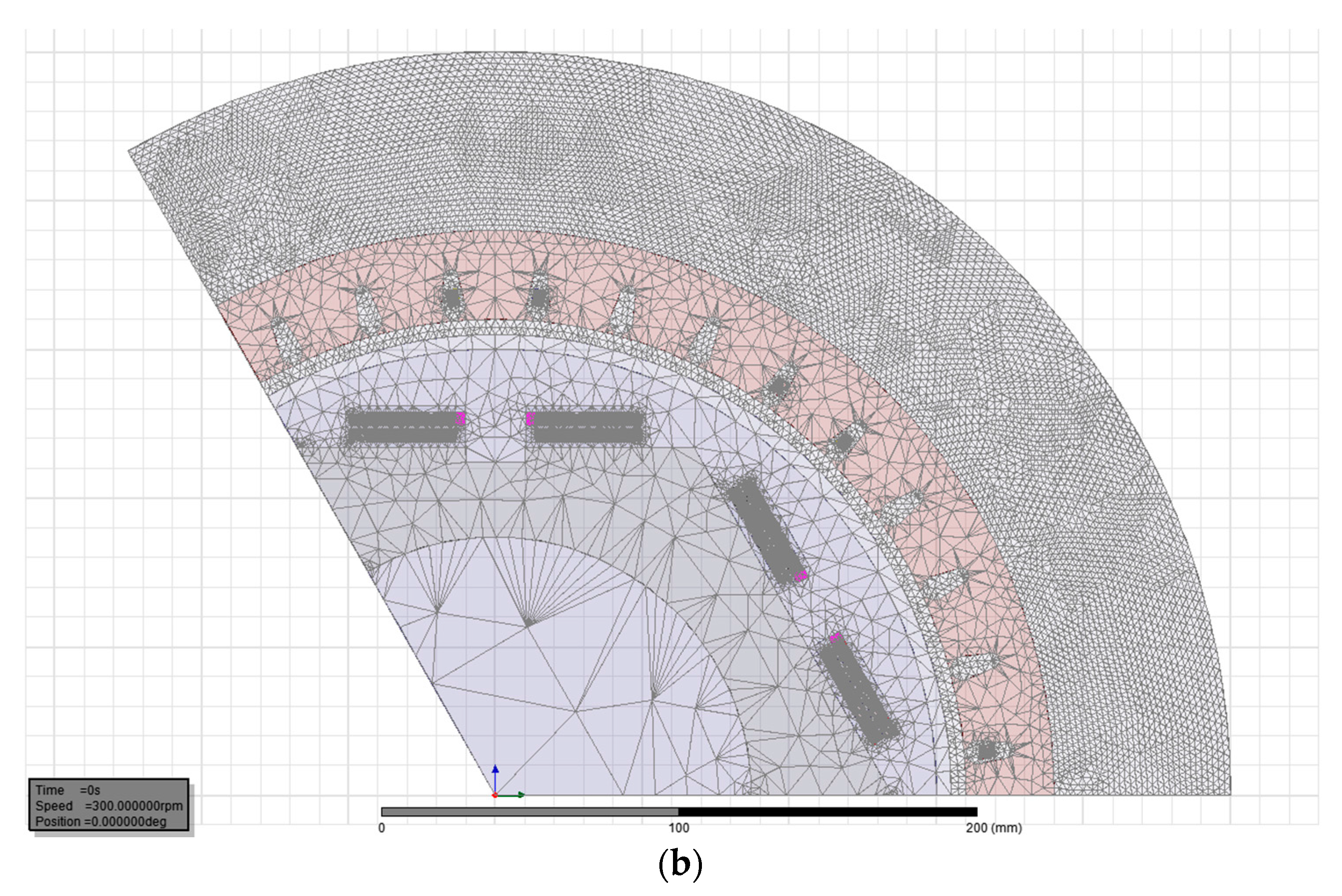
Mesh refinement in FEM analysis is critical, as a very fine mesh results in longer simulation time, and coarser mesh results in poorly resolved outputs. A trade-off was made in order to achieve reasonable accuracy within a practical time frame. Length-based mesh with an element size of 1 mm was chosen for field windings, stator conductors, and air gap. Coarse mesh with a larger element size of 3.5 mm was chosen for other parts (Figure 2b). The rotor core was left at the default mesh size set by ANSYS at > 3.5 mm, as it does not influence the effects being studied. The FEM simulation parameters are listed in Table 2. The use of the master-slave boundary condition helped with reducing the model size by making use of the symmetrical geometry of the machine [27].
3. Performance Analysis
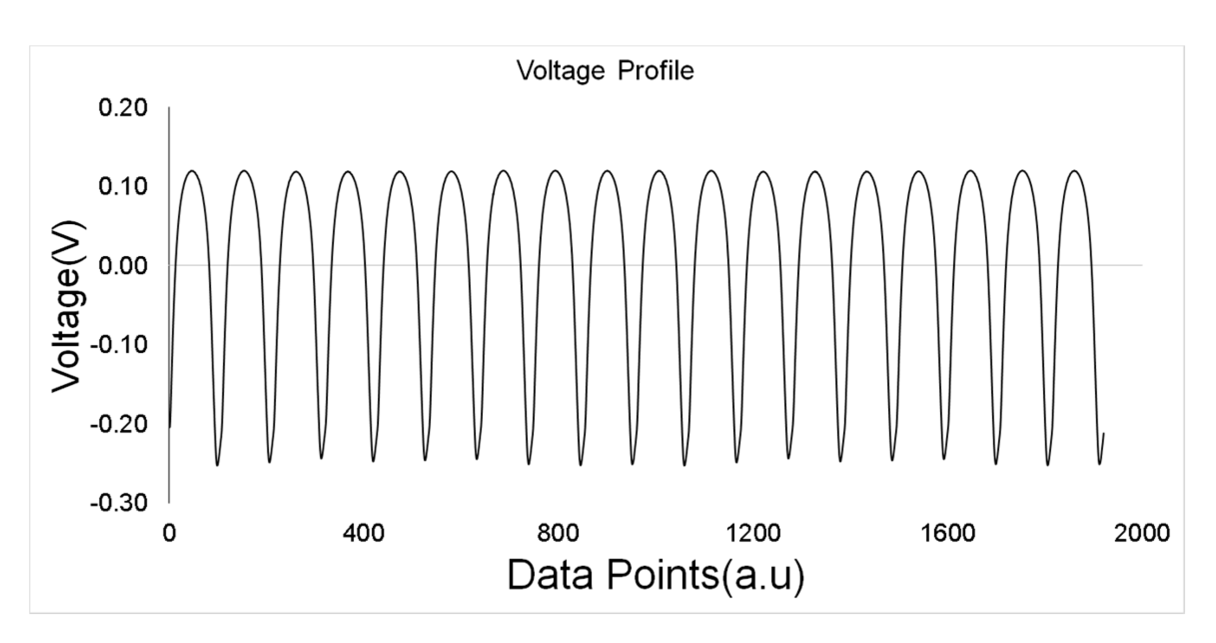
The flux pump offers a unique method of magnetising a superconductor without a physical link between the cryogenic and non-cryogenic environment [9,10,11,12,13,14]. Jiang et al. [15] have presented a formulation of a dynamic resistance model for a HTS flux pump, wherein the results show a linear relation between the frequency of the flux pump and the rate of current increase. From the voltage profile, it is evident that a net voltage (quasi-DC emf) drop occurs across the superconducting coil [7].
In the present study with the flux pump, the same trend was observed and the non-uniform voltage profile observed across the HTS stator (see Figure 3) is similar to that of Bumby et al. [16]. Based on the previous reported results [9], it is well established that the flux pump can be successfully used as an alternative to DC excitation for the field system in a generator. The voltage profiles obtained from experiments with flux pumps were used as excitation inputs to the FEM model discussed in Section 2.
As outlined in Section 1, the THD performance of a generator is one of the most critical parameters for the successful implementation of either a grid-connected generator or one used as a stand-alone supply for sensitive electronic loads. The range of this study covers the harmonic performance analysis of the proof of concept 10 kW HTS synchronous generator. The harmonic performance of a synchronous generator depends primarily on the rotor and stator construction [28,29].
The other factors that influence the harmonic performance are the nature of field excitation, the materials of the ferromagnetic circuit, armature reaction, load configuration, etc. In a previous work, we investigated and reported the no-load harmonic performance of the 10 kW HTS synchronous generator [25]. The minimum THD observed with the design was ~13%, which is low enough for the stand-alone operation of the generator with only heating load, but could not be used for grid-connected operation or electronic loads such as TV, Liquid Crystal Displays etc.
In this paper, we propose a stator design that considers three important parameters; (a) the stator yoke material, (b) winding pitch factor (Kp), and (c) load configuration.
3.1. Effect of Stator Yoke Material
In the above-mentioned work [25], we realized that FRP epoxy material is a better alternative to the commonly used steel yoke. The hysteresis in the ferromagnetic stator increases the ambient temperature around the cryostat of the HTS rotor and the ambient thermal load on the cryogenic system. In order to avoid the hysteresis loss, a non-ferromagnetic stator can be used. Hence, simulations were carried out with G10-FRP as the stator material in order to study the effects on the performance of generators with non-ferromagnetic stators.
The iron losses can be approximately expressed as follows:
where Ke is the eddy current coefficient of the material, f is the frequency, B is the magnetic field strength, and Kh is the hysteresis coefficient of the material.
For a non-conductor, the values of Ke and Kh are zero; hence, the iron losses can be reduced to zero with the use of a non-conducting stator frame. The use of non-ferromagnetic stator yoke results in a decrease of voltage levels as the field strength around the stator conductors decreases. The decrease in voltage levels has been compensated with an increase in the number of stator conductors. The increase in the number of stator conductors due to the usage of non-ferromagnetic yoke adds up to the capital cost, but avoids the recurring hysteresis losses.
3.2 Effect of Winding Pitch Factor (Kp)
The winding pitch of a generator is the number of slots spanned by each coil in the stator winding over the number of slots per pole (Figure 4). The winding pitch of generators is generally shortened from full pitch to either 5/6 (Figure 4b) or 2/3 (Figure 4c) in order to change the harmonic content of the output waveform. At the same time, the fundamental component of the output voltage is slightly lower than the full pitch winding. The reduction in the output voltage can be compensated by an increase in the field strength or the number of stator conductors. One of the leading manufacturers of synchronous generators-ABB uses both 5/6 and 2/3 pitched winding [30]. 5/6 is preferred for HV generators where compactness is preferred over reduced THD. The winding pitch factor Kp [31] gives the variation factor for different harmonics and is expressed as:
where N is the order of the harmonic.
Table 3 lists the values of Kp for 2/3 and 5/6 winding pitches. The value of Kp for the third harmonic with 2/3 pitch works out to be zero, thus eliminating the third harmonic component. This decreases the overall THD, but there is also a decrease in the voltage levels, which needs compensation.
3.3. Effect of Load Configuration
The harmonic performance of the HTS generator has been examined for “no load” and “rated load” conditions. The HTS generator in this discussion is aimed at implementation for wind-based power generation. In wind turbines, the best-suited alternator winding configuration is Star at the start-up in order to support an easy initial spin at high voltage and low current. The winding is switched to Delta once the speed has picked up to boost the current levels [32]. However, for low speed generation, as in this case, a fixed Star winding configuration for the alternator windings is deemed suitable.
Simulations were conducted for two different alternator winding and load winding configurations.
- Star-Star (S-S)
- Star-Delta (S-D)
The effect of the change in load configurations on the THD of the induced phase voltage will be discussed in the next section. The change in the load configuration has an effect on the field current as well; this effect is also discussed in next section.
4. Results and Discussion
4.1 Field Pattern
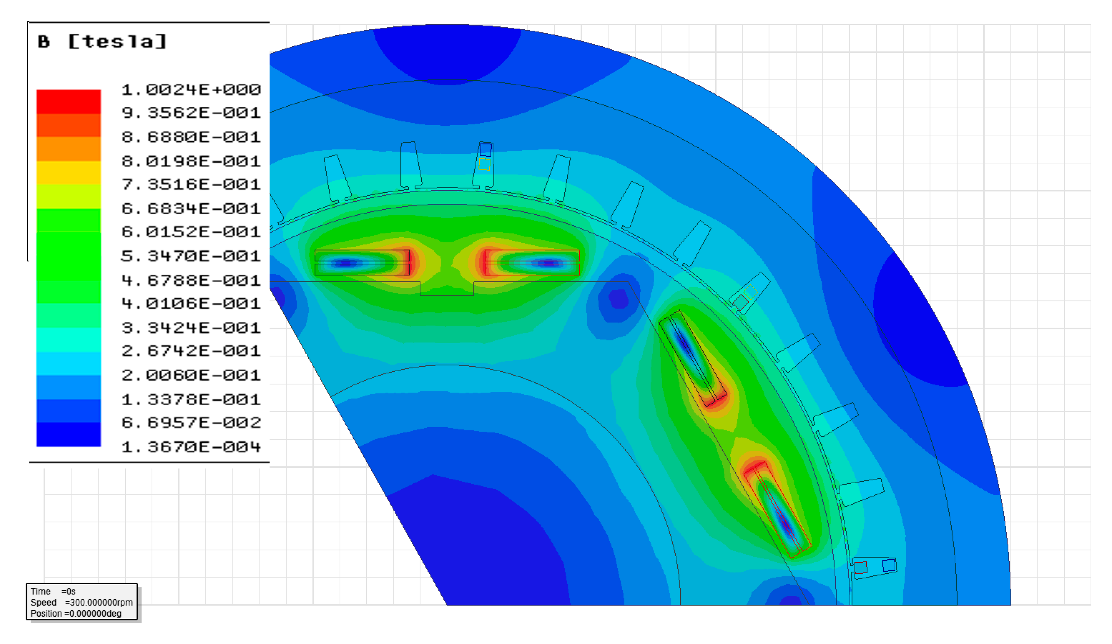
The field pattern with G10 as the stator material and flux pump excitation is observed to be uniform (Figure 5). The field variation at the stator location is minimal. The induced voltage waveforms (Figure 6) are consistent with the design expectations and have a lower THD than the designs we reported previously [25]. The harmonic analysis was carried out on the induced phase voltages. Normalised fast Fourier transform (FFT) and THD were computed using MATLAB 2015b. FFT and THD provide the quantitative measure of the different frequency components present in the induced voltage waveform.
4.2 Total Harmonic Distortion
THD is given by the following equation:
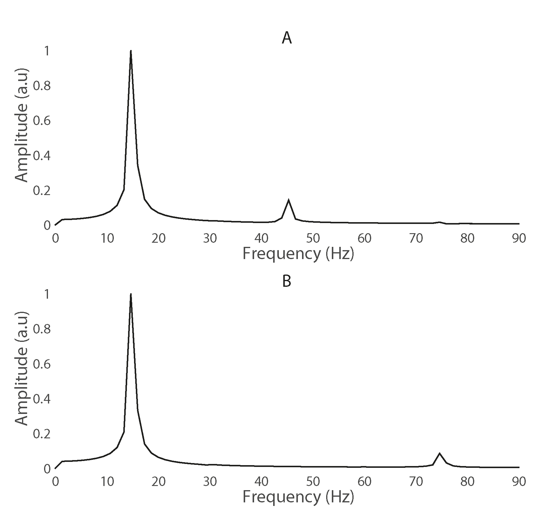
where k is an integer and refers to the harmonic order (k = 2, 3, 4…), Vk is the amplitude of kth order harmonic, and V1 is the fundamental frequency component. The improvement in THD for the 2/3 pitch configuration is clearly seen, and this is because of the elimination of the third harmonic component that is present in the 5/6 pitch configuration (see Figure 7).
Table 4, Table 5 and Table 6 show a comparison between the THD values of the induced phase voltage under different conditions. Simulations were carried out for three different frequencies of flux pump excitation (60 Hz, 120 Hz and 240 Hz). Under “no load” conditions, it was observed that the THD values with G10 stator were lower than those with the steel stator (Table 4). This reduction in THD can be attributed to higher fringing effects and sharper transition of the fields in the case of steel yoke stator for the hexagonal design of the rotor without pole shoes. The change in the winding pitch resulted in a decrease in the induced voltage levels, but improved the harmonic performance. The voltage levels were compensated by increasing the number of stator conductors, as mentioned in Section 3.
As discussed in Section 3, since the winding pitch is a critical factor in tuning the harmonic performance [33,34,35,36], results are analysed for two different pitches. The THD for the 2/3 pitch configuration is significantly reduced when compared to the 5/6 pitch configuration for both steel and G10 stator yokes. The reason for this improvement is the successful elimination of the third harmonic component (Figure 7). Based on these results, for further simulations, the stator yoke material was selected to be G10, and the winding pitch was selected to be 2/3.
Simulations for different loaded conditions (rated load, 1/2 rated and 1/4 rated loads) were carried out for two different configurations. Balanced resistive loads were coupled to the ANSYS Maxwell model using ANSYS Maxwell Circuit Editor for these simulations. With S-S configuration, the THD of the induced phase voltage (Vph) is ~3.3% lower than with the “no load” THD values (see Table 4 and Table 5).
On further investigation, it was observed that the field current profiles for the “no load” condition are affected by the pulsating nature of the flux pump excitation, whereas the pulsating effect does not have much of an effect under loaded conditions (see Figure 8). However, the field current is increasing in both of the cases; the field current oscillations in the case of the loaded condition have a higher sinusoidal variation than the field currents with the “no load” condition. For further simulations, Star-Delta (S-D) was selected as the load configuration. The THD values at different levels (Rated, 1/2 and 1/4 loads) are as tabulated in Table 6. Minimum THD is observed at rated load.
It is also observed that the THD values for the S-D configuration are slightly lower than the S-S configuration. This is most likely due to the lower armature reaction in the case of the S-D configuration. Studies on armature reaction and analyses of direct axis reactance (Xd) and quadrature axis reactance of the machine (Xq) of the machine are likely to give a better understanding of the ongoing phenomenon from magnetic field interaction. The THD limit as specified in IEEE STD 519-2014 is 5% for a bus voltage <69 kV at the point of common coupling, and the permitted limit is 8% for lower voltage generation <1 kV. Hence, the proof of concept generator to be tested in field and designed for 400 V meets prescribed standards.
The final commercial product based on this proof of concept generator will be a flux pump-integrated MW class wind turbine HTS generator, and the generated voltage levels for this generator are expected to be >1 kV and <69 kV. For this class of generation, the maximum limit of THD is 8%, as per the prescribed standard.
The observed THD limits are well within this limit, and with this design, a tolerance offset of ~3% can be considered for the additional harmonics introduced due to control circuitry and the power electronic switching circuitry, which will be integrated at different points of the generation and transmission. The overall variation trend of THD against various design parameters is shown in the bar graphs of Figure 9. It is seen that the S-D configuration with a pitch of 2/3 at rated load gives the least THD. The results are in consistence with the results observed for similar ironless machines [37].
As discussed in Section 3, the stator made of FRP epoxy (G-10) is better suited in cryogenic applications. In the absence of a ferromagnetic yoke, the field distribution is less concentrated and the drop in the field is higher, with a small increase in the distance from the centre of the field coil. To improvise the THD performance, design modifications were carried out on the stator geometry, and are discussed in the following sections.
4.3 Stator Design Improvement
4.3.1. Stator Design 1
4.3.2. Stator Design 2
From field and performance analysis of Design 1, it is understood that the conductors corresponding to the same phase are at different field levels. The reason is attributed to the absence of the ferromagnetic yoke of the stator. In order to avoid field non-uniformity, a different stator design is proposed, as shown in Figure 11, wherein the stator conductors could be placed in an adjacent manner rather than a stacked manner.
The two important variations in the design were:
- Stator slot width, and
- Internal diameter of the rotor.
The stator slot width was changed from 8 mm to 14 mm to accommodate the adjacent placement of all three phase stator conductors. The diameter on the yoke side was reduced from 380 mm to 360 mm, and the diameter on the gap side was increased from 302 mm to 312 mm. These variations were carried out to place the stator conductors for the same phase at the same field strength for most of the time, and decrease the fluctuations in the field level as well as the correspondingly in the induced voltage level. Thus, there was an expected decrease in the THD.
The field pattern with stator design 1 shows that the stator conductors corresponding to the same phase are at different field strengths (Figure 5). When the stator design changes, it is observed that the conductors corresponding to the same phase are in the same field strength, as required (Figure 12). The change in stator design resulted in an improvement in the harmonic performance of the machine. With the same meshing and boundary conditions as set for stator design 1, the change in the stator dimension and conductor placement strategy for a G-10 stator yoke resulted in a significant improvement in the harmonic performance; these results are shown in Table 7. The decrease in the harmonic distortion validates that field uniformity is one of the important factors in ascertaining a better harmonic performance.
5. Conclusions
The effects of stator design on the harmonic performance of the generator were carried out. It has been successfully shown that the flux pump can be an alternative to DC source for exciting the field system in an HTS generator, even for loaded conditions such as S-S or S-D configurations. The results indicate that the variation in the parameters such as stator yoke material, winding pitch, and loading configuration affect the harmonic performance significantly. The stator material has a significant effect on the THD of the induced voltage. The use of non-ferromagnetic stator materials (G10) leads to a decrease in the THD. The different excitation frequencies of the flux pump have negligible effects on the THD of the induced voltage. Based on the simulations with different winding pitches, a winding pitch of 2/3 is the best suited for this machine. The simulations on the load configurations indicate that the S-D configuration would result in the smallest value of THD. The most suitable configuration with respect to the stator yoke material, winding pitch, and load configuration to minimize the THD of a 10 kW HTS generator has been established. A better stator conductors’ placement and stator design strategy to reduce harmonic distortion have been analytically deduced. Further work on the geometrical design improvisation of the stator windings, and separately excited field coils to avoid quenching and total failure of the system, are currently in progress.
Acknowledgments
The authors would like to acknowledge the support from Robinson Research Institute, Victoria University of Wellington, New Zealand, Auckland University of Technology, New Zealand and Changwon National University, South Korea.
Author Contributions
Ravichandra Kulkarni, Krishanamachar Prasad and Tek Tjing Lie conceived and designed the simulation study and experiments; Ravichandra Kulkarni, Rodney A. Badcock, Chris W. Bumby and Hae Jin Sung conducted flux pump experiments and analyzed the data; Rodney A Badcock, Hae Jin Sung provided the solidworks model of the HTS generator; Ravichandra Kulkarni wrote the paper.
Conflicts of Interest
The authors declare no conflict of interest.
References
- Kalsi, S.S. Application of High Temperature Superconductors to Electric Power Equipment; John Wiley & Sons: Hoboken, NJ, USA, 2011. [Google Scholar]
- Qu, R.; Liu, Y.; Wang, J. Review of Superconducting Generator Topologies for Direct-Drive Wind Turbines. IEEE Trans. Appl. Supercond. 2013, 23, 5201108. [Google Scholar]
- Kalsi, S.S.; Henderson, N.; Gritter, D.; Nayak, O.; Gallagher, C. Benefits of HTS technology to ship systems. In Proceedings of the IEEE Symposium on Electric Ship Technologies, Philadelphia, PA, USA, 27 July 2005. [Google Scholar]
- Kalsi, S.S.; Weeber, K.; Takesue, H.; Lewis, C.L.; Neumueller, H.W.; Blaugher, R.D. Development status of rotating machines employing superconducting field windings. Proc. IEEE. 2004, 92, 1688–1704. [Google Scholar] [CrossRef]
- Nick, W.; Nerowski, G.; Neumüller, H.W.; Frank, M.; Van Hasselt, P.; Frauenhofer, J.; Steinmeyer, F. 380 kW synchronous machine with HTS rotor windings—Development at Siemens and first test results. Phys. C Supercond. 2002, 372–376, 1506–1512. [Google Scholar] [CrossRef]
- Barnes, P.N.; Sumption, M.D.; Rhoads, G.L. Review of high power density superconducting generators: Present state and prospects for incorporating YBCO windings. Cryogenics 2005, 45, 670–686. [Google Scholar] [CrossRef]
- Jeong, S.; Kim, Y. Thermal anchoring of conduction-cooled current leads for superconductivity applications near liquid nitrogen temperature. Cryogenics 2010, 50, 287–291. [Google Scholar] [CrossRef]
- Bumby, C.W.; Pantoja, A.E.; Sung, H.J.; Jiang, Z.; Kulkarni, R.; Badcock, R.A. Through-Wall Excitation of a Magnet Coil by an External-Rotor HTS Flux Pump. IEEE Trans. Appl. Supercond. 2016, 26, 1–5. [Google Scholar] [CrossRef]
- Kulkarni, R.; Prasad, K.; Lie, T.T. Flux pump for HTS rotating machinery applications. In Proceedings of the 2015 IEEE Eindhoven PowerTech 2015, Eindhoven, The Netherlands, 29 June–2 July 2015. [Google Scholar]
- Nakamura, T.; Sugano, M.; Doi, T.; Amemiya, N. Flux Pumping Effect of HTS Films in a Traveling Magnetic Field. IEEE Trans. Appl. Supercond. 2010, 20, 1033–1036. [Google Scholar] [CrossRef]
- Ishmael, S.; Goodzeit, C.; Masson, P.; Meinke, R.; Sullivan, R. Flux Pump Excited Double-Helix Rotor for Use in Synchronous Machines. IEEE Trans. Appl. Supercond. 2008, 18, 693–696. [Google Scholar] [CrossRef]
- Hoffmann, C.; Walsh, R.; Karrer-Mueller, E.; Pooke, D. Design Parameters for an HTS Flux Pump. Phys. Procedia 2012, 36, 1324–1329. [Google Scholar] [CrossRef]
- Hoffmann, C.; Pooke, D.; Caplin, A.D. Flux Pump for HTS Magnets. IEEE Trans. Appl. Supercond. 2011, 21, 1628–1631. [Google Scholar] [CrossRef]
- Coombs, T.; Hong, Z.; Zhu, X. A thermally actuated superconducting flux pump. Phys. C Supercond. 2008, 468, 153–159. [Google Scholar] [CrossRef]
- Jiang, Z.; Hamilton, K.; Amemiya, N.; Badcock, R.A.; Bumby, C.W. Dynamic resistance of a high-Tc superconducting flux pump. Appl. Phys. Lett. 2014, 105, 112601. [Google Scholar] [CrossRef]
- Bumby, C.W.; Badcock, R.A.; Sung, H.J.; Kim, K.M.; Jiang, Z.; Pantoja, A.E.; Buckley, R.G. Development of a brushless HTS exciter for a 10 kW HTS synchronous generator. Supercond. Sci. Technol. 2016, 29, 024008. [Google Scholar] [CrossRef]
- Mawardi, O.; Muelder, S.; Michelotti, R. Brushless superconducting alternators. IEEE Trans. Magn. 1977, 13, 780–783. [Google Scholar] [CrossRef]
- Muta, I.; Tsukiji, H.; Hoshino, T.; Mukai, E. Electrical characteristics of fully superconducting synchronous generator in persistent excitation mode. IEEE Trans. Magn. 1992, 28, 434–437. [Google Scholar] [CrossRef]
- Muta, I.; Tsukiji, H.; Hoshino, T.; Mukai, E. Output power limit of 200 MW class brushless superconducting generator excited with magnetic flux-pump. IEEE Trans. Appl. Supercond. 2001, 11, 2335–2338. [Google Scholar]
- Ferendeci, A.; Mawardi, O.; Melfi, M.; Laquer, H. Flux pump excited brushless alternator. IEEE Trans. Magn. 1981, 17, 146–148. [Google Scholar] [CrossRef]
- Vashi, A. Harmonic Reduction in Power System. Master’s Degree, California State University, Sacramento, CA, USA, 8 June 2010. [Google Scholar]
- Wakileh, G.J. Harmonics in rotating machines. Electr. Power Syst. Res. 2003, 66, 31–37. [Google Scholar] [CrossRef]
- Miller, T.J.E.; Hughes, A. Comparative design and performance analysis of air-cored and iron-cored synchronous machines. Proc. Inst. Electr. Eng. 1977, 124, 127–132. [Google Scholar] [CrossRef]
- Hughes, A.; Miller, T.J.E. Analysis of fields and inductances in air-cored and iron-cored synchronous machines. Proc. Inst. Electr. Eng. 1977, 124, 121–126. [Google Scholar] [CrossRef]
- Kulkarni, R.; Prasad, K.; Lie, T.T.; Badcock, R.A.; Bumby, C.W.; Sung, H.J. FEM and performance analysis of 10 kW HTS generator with flux pump excitation. In Proceedings of the 2016 IEEE International Conference on Power System Technology (POWERCON), Wollongong, Australia, 28 September–1 October 2016. [Google Scholar]
- Khalf, M.A.; Wamkeue, R.; Aguglia, D. Finite element approach for performances prediction of a small synchronous generator using ANSYS software. In Proceedings of the 25th IEEE Canadian Conference on Electrical & Computer Engineering (CCECE), Montreal, QC, Canada, 29 April–2 May 2012. [Google Scholar]
- ANSYS Maxwell Manual. Available online: https://support.ANSYS.com/portal/site/ANSYSCustomerPortal/template.fss?file=%2Fsolutions%2Fattach%2FMAXWELL.pdf (accessed on 29 August 2017).
- Shafaie, R.; Kalantar, M. Design of a 10-MW-Class Wind Turbine HTS Synchronous Generator with Optimized Field Winding. IEEE Trans. Appl. Supercond. 2013, 23, 5202307. [Google Scholar] [CrossRef]
- Seo, J.H.; Han, K.J.; Choi, H.S.; Lee, S.H.; Hahn, S.; Lee, H. Comparison Study on Harmonic Loss of MW-Class Wind Generators with HTS Field Winding. IEEE Trans. Appl. Supercond. 2014, 24, 1–5. [Google Scholar] [CrossRef]
- Technical Note. Available online: library.e.abb.com/public/8d5deb3fe4638051c1257c9400508282/Technical%20note%20Winding%20pitch%20LR_040214.pdf (accessed on 25 August 2017).
- Nelson, J.P. A better understanding of harmonic distortion in the petrochemical industry. IEEE Trans. Ind. Appl. 2004, 40, 220–231. [Google Scholar] [CrossRef]
- Butcher Charles, A. Synchronous Machine Starting System. U.S. Patent 1,804,591, 12 May 1931. [Google Scholar]
- Zhang, L.; Huang, Y.; Dong, J.; Guo, B.; Zhou, T. Stator winding design of induction motors for high efficiency. In Proceedings of the 17th International Conference on Electrical Machines and Systems (ICEMS), Hangzhou, China, 22–25 October 2014. [Google Scholar]
- Smith, R.; Layton, J.M. Harmonic elimination in poly-phase machines by graded windings. Proc. Inst. Electr. Eng. 1963, 110, 1640–1648. [Google Scholar] [CrossRef]
- Alternator Winding Pitch and Power System Design. Available online: https://power.cummins.com/technical-papers (accessed on 29 August 2017).
- Say, M.G. Alternating Current Machines, 4th ed.; Pitman Publishing Ltd.: London, UK, 1976. [Google Scholar]
- Zhang, Z.; Molinas, M.; Matveev, A.; Nilssen, R.; Nysveen, A. Efficiency calculation and improvement of a large-diameter ironless permanent magnet generator. In Proceedings of the 2012 15th International Conference on Electrical Machines and Systems (ICEMS), Sapporo, Japan, 21–24 October 2012. [Google Scholar]
Figure 1.
High-temperature superconducting (HTS) generator-ANSYS 3D model.

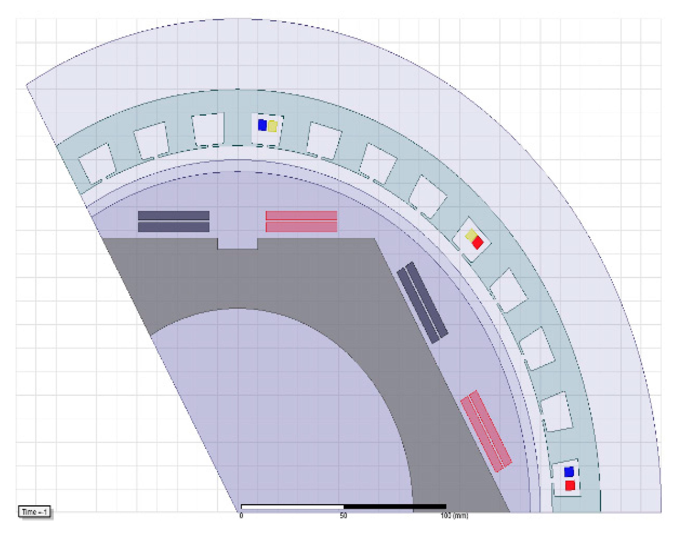
Figure 2.
(a) ANSYS Maxwell 3D finite element model (FEM) pie model of a HTS generator; (b) mesh plot of pie section of the 2D FEM model.
Figure 2.
(a) ANSYS Maxwell 3D finite element model (FEM) pie model of a HTS generator; (b) mesh plot of pie section of the 2D FEM model.


Figure 3.
Voltage profile across the flux pump stator.

Figure 4.
Stator conductor placement: (a) full pitch; (b) 5/6 pitch; (c) 2/3 pitch.

Figure 5.
ANSYS field pattern with G10 stator yoke (stator design 1).

Figure 6.
ANSYS plot of induced three-phase voltage.

Figure 7.
Normalised fast Fourier transform (FFT) plot of induced phase voltage at rated load: (A) pitch = 5/6; (B) pitch = 2/3.
Figure 7.
Normalised fast Fourier transform (FFT) plot of induced phase voltage at rated load: (A) pitch = 5/6; (B) pitch = 2/3.

Figure 8.
Field current oscillations with respect to the loading condition.

Figure 9.
The variation of total harmonic distortion (THD) with material, pitch and load configurations.
Figure 9.
The variation of total harmonic distortion (THD) with material, pitch and load configurations.

Figure 10.
2D model with stator design 1.

Figure 11.
2D model with stator design 2.

Figure 12.
ANSYS field pattern with G10 stator yoke (stator design 2).


Table 1.
HTS Generator Parameters.
| Parameter | Value |
|---|---|
| Rating | 10 kW |
| HTS Coil Temperature | 30K |
| Rated Voltage | 400 V |
| Poles | 6 |
| Speed | 300 rpm |
| Frequency | 15 Hz |
| Type of Rotor | HTS |
| HTS Winding | Racetrack |
| HTS Wire | SuNam |
| Coil Thickness | 35.25 mm |
| Turns in field coil | 235 |
| Rated field current | 98 A |
| Field current margin | 40% |
| Rotor shaft length | 315 mm |
| Total diameter | 497 mm |
Table 2.
FEM Simulation Parameters.
| Boundary Conditions | Vector Potential & Master Slave |
|---|---|
| Mesh type | Length based |
| Analysis type | Magnetic transient |
| Time step | 0.2 ms |
| Total simulation time | 750 ms |
Table 3.
Winding Pitch Factor.
| Winding Pitch Factor (Kp) | ||
|---|---|---|
| Component | 2/3 Pitch | 5/6 Pitch |
| Fundamental | 0.87 | 0.97 |
| 3rd Harmonic | 0.00 | 0.71 |
| 5th Harmonic | 0.87 | 0.26 |
| 7th Harmonic | 0.87 | 0.26 |
Table 4.
No load THD (Vph) [22].
Table 4.
No load THD (Vph) [22].
| f (Hz) | Pitch = 5/6 | Pitch = 2/3 | ||
|---|---|---|---|---|
| Steel | G10 | Steel | G10 | |
| 60 | 15.56 | 13.40 | 8.59 | 6.13 |
| 120 | 15.56 | 13.41 | 8.60 | 6.14 |
| 240 | 15.57 | 13.41 | 8.61 | 6.14 |
Table 5.
Rated load G10 Stator 2/3 Pitch.
| f (Hz) | Star-Star | Star-Delta |
|---|---|---|
| 60 | 5.91 | 5.21 |
| 120 | 5.91 | 5.22 |
| 240 | 5.98 | 5.22 |
Table 6.
Star-Delta G10 Stator 2/3 Pitch.
| f (Hz) | THD (Vph) | ||
|---|---|---|---|
| Rated Load | 1/2 Rated Load | 1/4 Rated Load | |
| 60 | 5.21 | 5.84 | 6.05 |
| 120 | 5.22 | 5.84 | 6.05 |
| 240 | 5.22 | 5.84 | 6.05 |
Table 7.
THD Comparison between Design 1 and Design 2.
| f (Hz) | No Load THD | Rated Load THD | ||
| Design 1 | Design 2 | Design 1 | Design 2 | |
| 60 | 6.1367 | 4.2915 | 5.2164 | 2.7269 |
| 120 | 6.1378 | 4.3016 | 5.2196 | 2.7366 |
| 240 | 6.1383 | 4.3155 | 5.2243 | 2.7398 |
© 2017 by the authors. Licensee MDPI, Basel, Switzerland. This article is an open access article distributed under the terms and conditions of the Creative Commons Attribution (CC BY) license (http://creativecommons.org/licenses/by/4.0/).
Share and Cite
MDPI and ACS Style
Kulkarni, R.; Prasad, K.; Tjing Lie, T.; Badcock, R.A.; Bumby, C.W.; Sung, H.-J. Design Improvisation for Reduced Harmonic Distortion in a Flux Pump-Integrated HTS Generator. Energies 2017, 10, 1344. https://doi.org/10.3390/en10091344
AMA Style
Kulkarni R, Prasad K, Tjing Lie T, Badcock RA, Bumby CW, Sung H-J. Design Improvisation for Reduced Harmonic Distortion in a Flux Pump-Integrated HTS Generator. Energies. 2017; 10(9):1344. https://doi.org/10.3390/en10091344
Chicago/Turabian StyleKulkarni, Ravichandra, Krishnamachar Prasad, Tek Tjing Lie, Rodney A. Badcock, Chris W. Bumby, and Hae-Jin Sung. 2017. "Design Improvisation for Reduced Harmonic Distortion in a Flux Pump-Integrated HTS Generator" Energies 10, no. 9: 1344. https://doi.org/10.3390/en10091344
Note that from the first issue of 2016, this journal uses article numbers instead of page numbers. See further details here.