In this section, the effect on load power and efficiency due to the additional LCC compensation components is analysed. Lf is allowed to vary from 0.1 M12 to 2 M12 in 0.2 M12 steps. The performance of the LCC-WPT system is compared with an SS-WPT system under the condition of the same input DC voltage. The self-inductance of the transmit and receive coils is 66 μH, the coupling coefficient is 0.27, and the DC input voltage is 100 V.
3.1. Efficiency Oriented Design of the LCC-WPT System
As the SS-WPT system is treated as the benchmark in this study, the following analysis aims at determining the conditions for higher efficiency in the LCC-WPT system, then the SS-WPT system with given specified transmit and receive coils; therefore the following inequality should be met in Equation (28).
From Equations (13)–(24), it can be found that the vector currents flowing in the primary and secondary sides of the LCC-WPT system are very complex to express, making the inequality (28) very difficult to solve.
If the stray resistance on the coils and capacitors is neglected for simplicity, then for the SS-WPT system, by substituting the current expressions into the power expression and the efficiency expression, the primary side power, the secondary side power and the system efficiency can be expressed as (29)–(31) at the resonant condition. It can be found that the system efficiency is only related to the resonance frequency, load resistance, mutual inductance and equivalent resistance of the driver.
Following the same approach applied in the analysis of SS-WPT system, the resistance on all the inductors and capacitors in the LCC-WPT system are also neglected for simplicity, and since the LCC-WPT system has a symmetrical structure, expressions (32)–(35) are valid.
Now, the power transferred from the primary side, the power received by the secondary side and the system efficiency of the LCC-WPT system can be expressed as Equations (36)–(38).
Comparing Equation (31) and Equation (38), it can be noticed that an extra variable Lf is introduced in the LCC-WPT system which affects the efficiency of the system.
Substitute Equations (31) and (38) into Equation (28), the inequality is gained as in Equation (39).
After some simple mathematical manipulations, inequality Equation (39) can be simplified as Equation (40).
Equations (1)–(39) now provide the mathematical proof, and inequality (40) specifies the required conditions for the system efficiency of an LCC-WPT system to be higher than that of an SS-WPT system. It means that as long as Lf > M12, the LCC-WPT system has higher energy efficiency than the SS-WPT system for the same extended transfer distance and same load resistance with same transmit and receive coils. However, this analysis has neglected coil and capacitor ESR, and therefore is only approximately true when the parasitic resistance on all the components are small enough and can be neglected, and if the parasitic resistance cannot be ignored, the inequality (40) does not hold any longer, as is shown by simulation and experiment for a practical system.
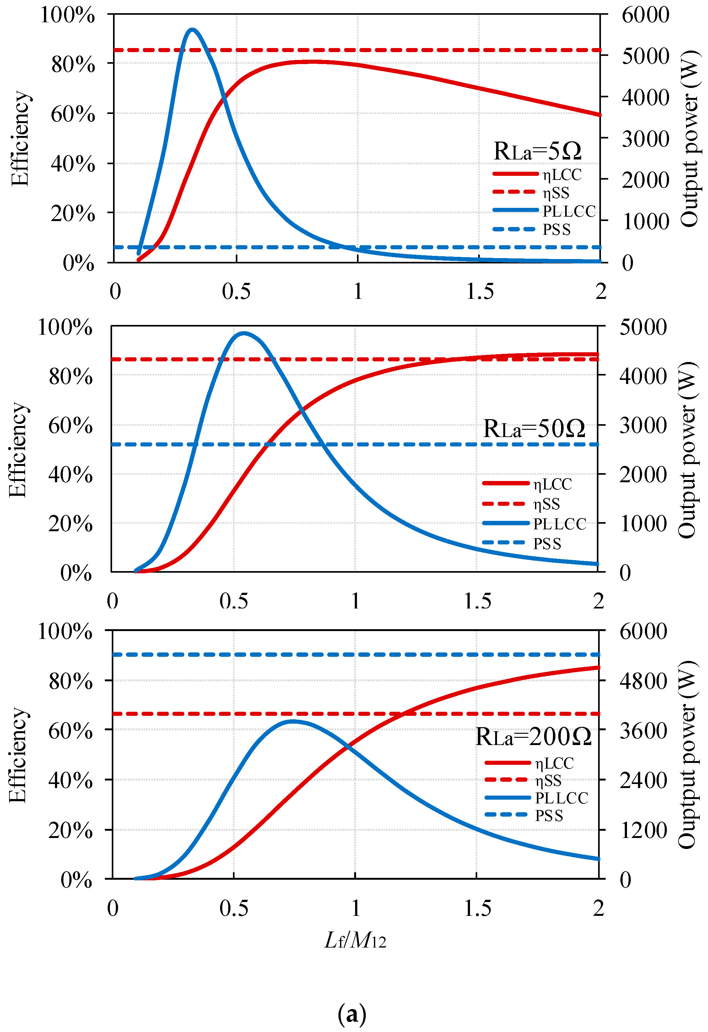
The calculated variation of the system efficiency and output power of the LCC-WPT system according to Equations (29)–(38) are plotted in
Figure 4 against the variation of the compensation inductance
Lf, where the SS-WPT system and the LCC-WPT system have the same DC input voltage and load resistance. The parasitic resistances are neglected as in the previous analysis.
In
Figure 4, the red lines are the system efficiency, and blue lines are the system output power, the solid lines stand for the LCC-WPT system, and the dotted lines stand for the SS-WPT system. It can be seen from
Figure 4 that with
Lf increasing, the LCC-WPT system efficiency shows a rising trend, and when
Lf exceeds
M12, the efficiency of LCC-WPT system will exceed the system efficiency of the equivalent SS-WPT system as expected; with
Lf further increasing, the efficiency curve of LCC-WPT will continue to increase but will be limited by
RS. Focusing on the system output power in
Figure 4, there is a peak value for the LCC-WPT system when
Lf ≈ 0.6
M12, which is much higher compared to the output power of the SS-WPT system. And it can also be seen that there are two values of
Lf which can make the LCC-WPT system output the same power as the SS-WPT system, one of these two is when
Lf =
M12.
3.2. Output Power Regulation of the LCC-WPT System
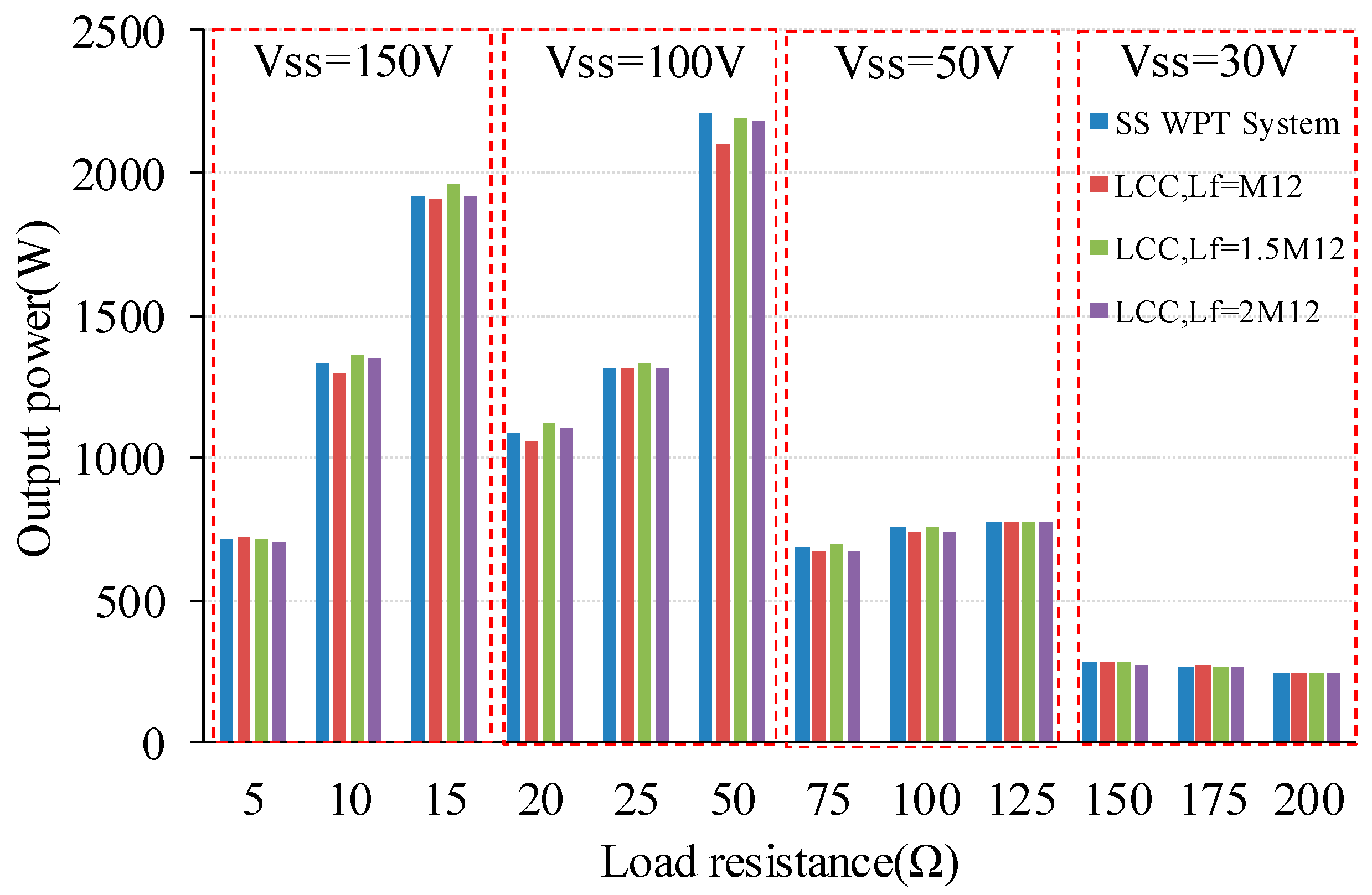
Another perspective to compare the two compensation topologies is to look at their performance (efficiency and component stresses) when they have the same power transfer capacity with identical load condition and coil-to-coil distance. Therefore, this part aims at designing these two WPT systems for the same output power.
From
Figure 4, it is seen that the output power curves of the LCC system cross over with the output power of the SS-WPT system at two values of
Lf; therefore, one way to tune the output power is to tune
Lf with same DC input voltage and load resistance. Based on Equations (30) and (37), in order to design an LCC-WPT system with equal output power as an SS-WPT system as expressed in Equation (41), the inductance of
Lf can be tuned to achieve this goal without changing any other parameters of the LCC-WPT system.
By substituting Equations (30) and (37) into Equation (41), a simple inequality, Equation (42), can be derived.
However, according to the previous analysis,
Lf >
M12 is needed in order to achieve higher efficiency for the LCC-WPT system. Therefore, another approach to regulate the output power is to tune the DC-link voltage according to (37). The DC voltage in the LCC-WPT system can be tuned to meet the output power requirement with arbitrary
Lf. In this case, the required DC input voltage can be obtained from Equations (30) and (37) as in Equation (43) when the inverter is assumed to have the same voltage ratios, i.e., the relationship between
VDC and the fundamental RMS voltage of the square wave driving voltage for the two WPT systems. In the latter analysis,
VDC_SS and
VDC_LCC are shortened as
VSS and
VLCC respectively.
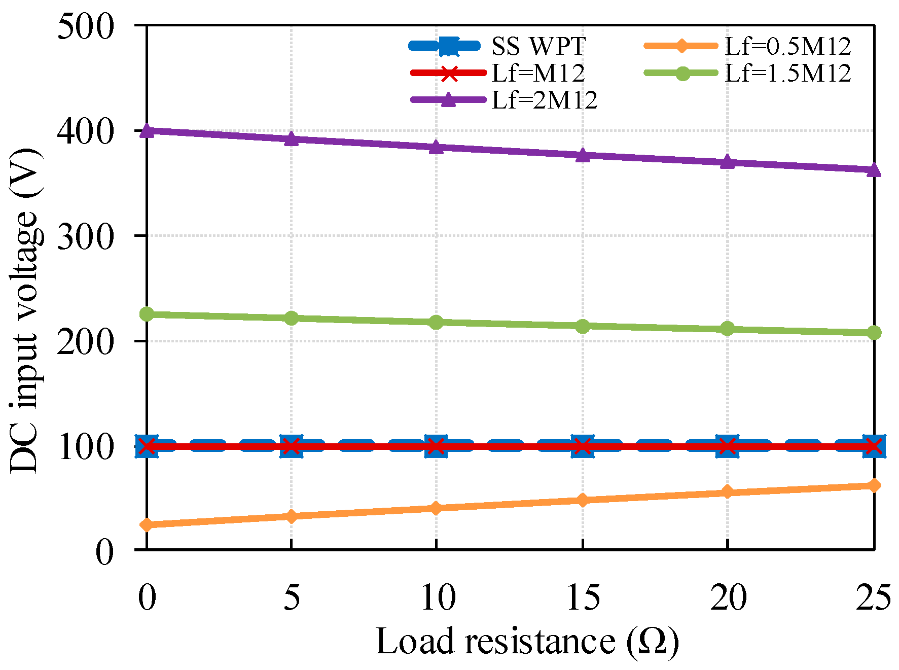
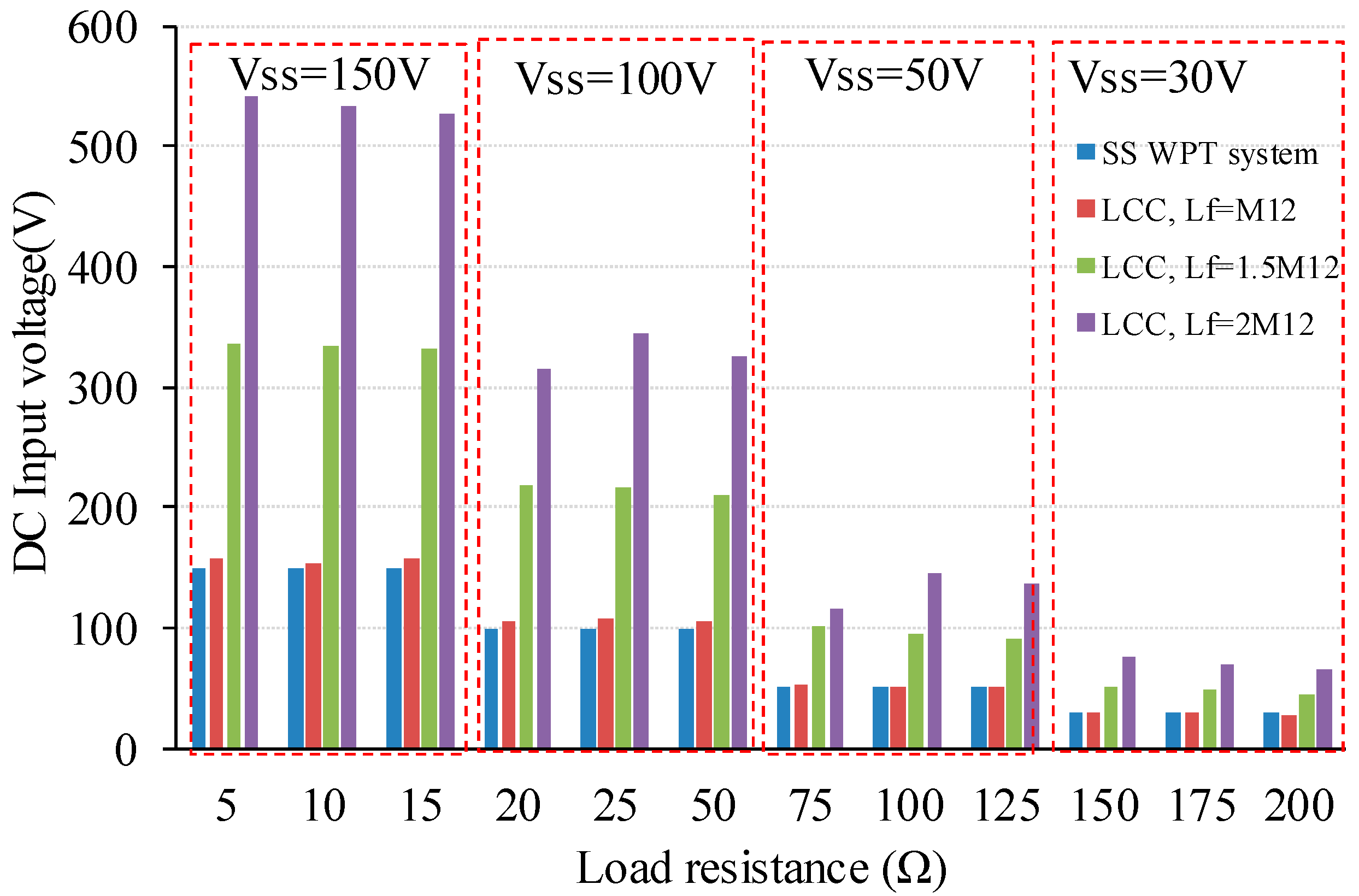
Based on Equation (43), the variations of required
VLCC are plotted in
Figure 5 with respect to various
Lf and
RL. In this calculation, the equivalent voltage source internal resistance is set to be 0.5 Ω, but this value will vary according to the practical system operating condition.
It can be seen from
Figure 5 that, when
Lf =
M12, the system input DC voltage does not need to be adjusted to get the same output power as the SS-WPT system. When
Lf is smaller than
M12 (
Lf = 0.5
M12), the required DC input voltage of the LCC-WPT system is smaller than that of the SS-WPT system, but the system efficiency will be lower, with a smaller
Lf from
Figure 4, the required input power and current will be higher in order to hold the output power constant, which will not only decrease the system efficiency, but also stress the switching devices in the inverter. When
Lf is greater than the
M12 (e.g.,
Lf = 1.5
M12,
Lf = 2
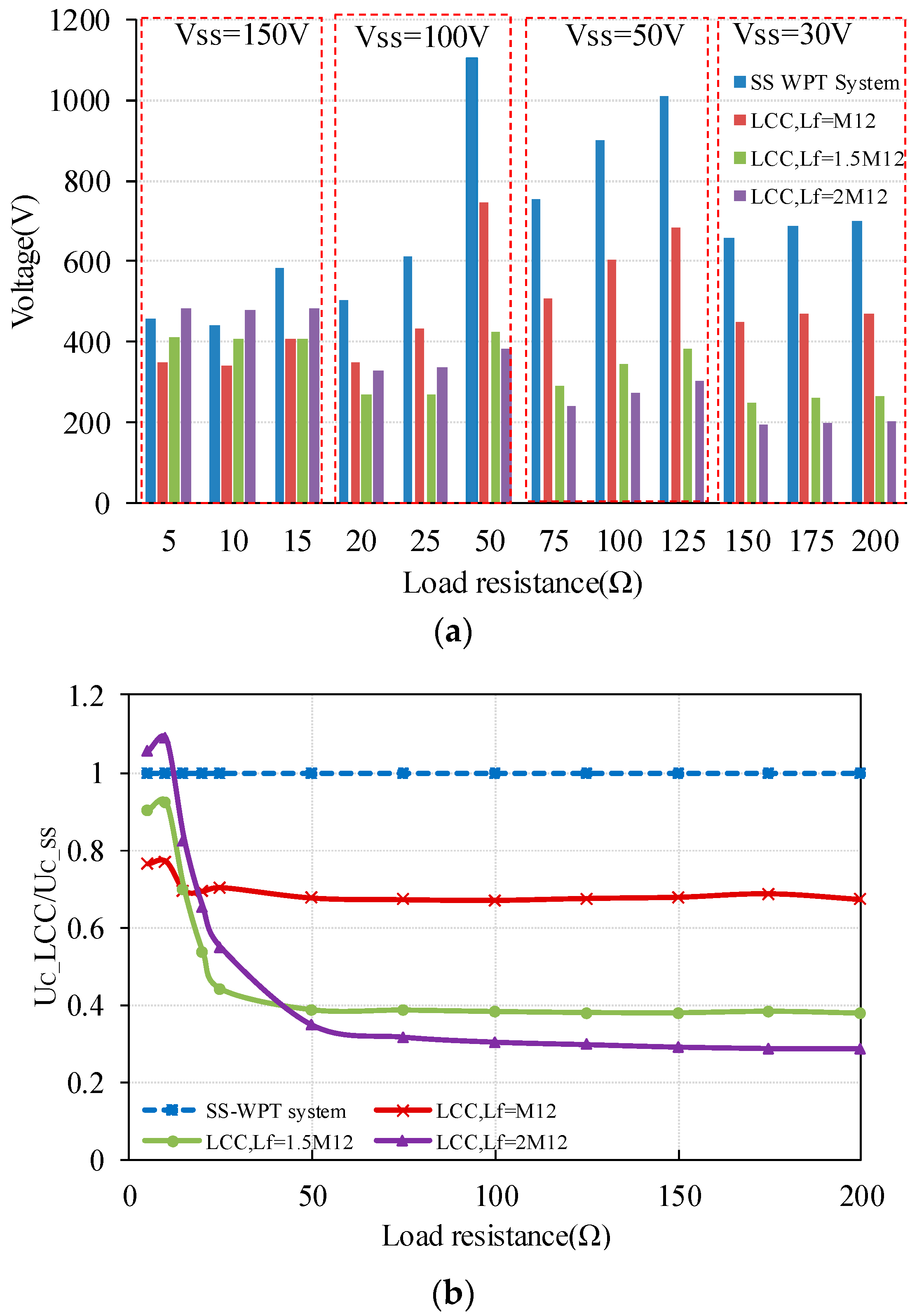
M12), even though the system efficiency can be improved, the input DC voltage of the LCC-WPT system will be much higher than the SS-WPT system, which will increase voltage stress on the components used in the LCC-WPT system. The extra voltage can lead to higher failure rate of the components. The higher
Lf is, the higher the DC input voltage required.
Therefore, while utilizing the VDC tuning approach to adjust the output power, the stress on the system components should be considered, and this will be studied in the next section. It should be noticed that DC input voltage tuning approach can only provide approximate values, and requires manual tuning in a practical system to obtain the desired output power, as the calculations are based on ideal components, and RS will vary according to the system operating condition.
3.3. Analysis of the Impacts Caused by Lf
A generalised expression presented in this paper, which includes parasitic resistances in the coil-system, was found to be long and unwieldy; therefore some simplifying assumptions are used in this paper. In order to validate these assumptions, a simulation is used to predict the true system efficiency.
Li et al. [
17] give an equation for calculating transferred power using the same assumptions as in this paper, where the effect of circuit resistances are neglected, i.e., coil resistance and capacitor ESR. Due to the high circulating currents, these can have a considerable effect on system efficiency, as seen in
Table 1, which shows a comparison between the simulated results and the calculated results. The simulation model is based on the experimental system used here with coil resistance and capacitor ESR. The parasitic resistances of the components used in the LCC-WPT system are listed in
Table 2. All the compensation capacitors are assumed to have the same ESR value of 80 mΩ, based on calculation and measurement, and are made from series/parallel combinations to keep stresses within safe limits. Also, because in [
17], the transferred power is the output power of the inverter, in order to maintain consistency with them, in Equations (13), (26) and (37),
RS is set to be zero and
VS is replaced by
U1, and the efficiency is the coil-to-coil efficiency (input power of the rectifier divided by the output power of the inverter).
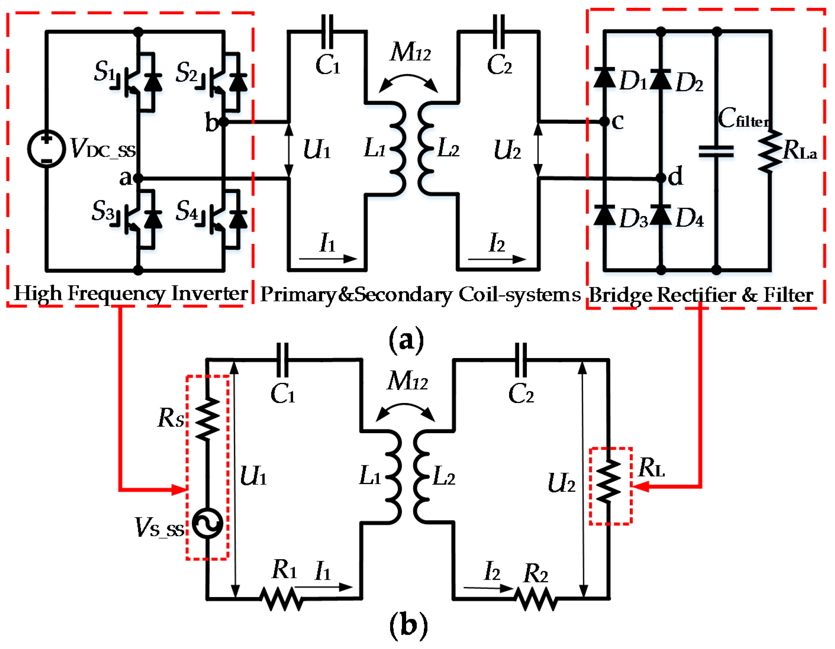
Clearly, the resistance of the coils and capacitors cannot be neglected when arriving at an accurate estimation of system performance. To determine the effects of the additional LCC components, simulation models for the SS-WPT system and the LCC-WPT system are built up using MATLAB/Simulink, as the MATLAB/Simulink has a rapid accelerator function which can greatly reduce the simulation time. The two WPT system models are based on the whole WPT system models as shown in
Figure 1a and
Figure 2a. In the simulation, the load resistance is set to be 5 Ω, 50 Ω and 200 Ω to provide different conditions. The other simulation parameters for the SS-WPT and LCC-WPT system have been listed in
Table 2; it should be noticed that the parasitic resistance of the components are not exactly equal to practical values, because the combination of the compensation capacitor tank will be tuned to satisfy Equations (5) and (20). In order to have a more precise and meaningful consideration of the parasitic resistance of the compensation components, except for the previous assumption, another assumption is made in that all the compensation capacitors have the same parasitic resistance, and all the inductors have the same quality factor. Therefore, when the compensation inductor changes, even though the ESR of the inductor will vary, the quality of the inductor will keep constant, which is an important parameter when considering the system efficiency. Also, because the transmit and receive coils are fixed, therefore, the quality factor of the coils is treated as the benchmark, and then a meaningful ESR for the additional compensation inductor can be derived. The results are plotted as in
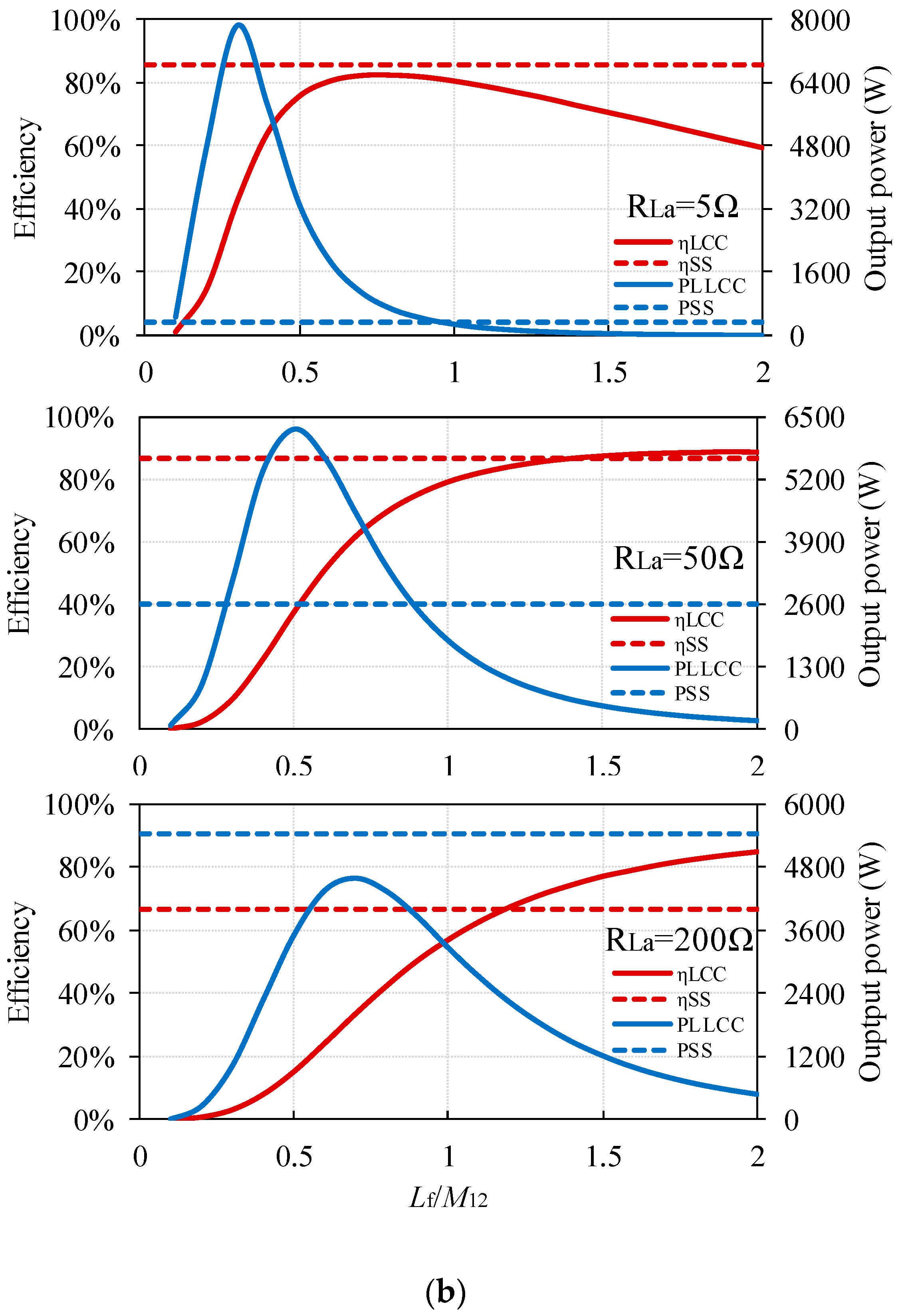
Figure 6 under different assumptions.
Figure 6 shows the simulation schematics for particular operating conditions. Firstly, it can be seen that both these two assumptions can provide similar results on the analysis of the impacts caused by the
Lf on the WPT system performance particularly on the system efficiency, the difference between these two results are mainly on the system output power which is caused by the parasitic resistance of the
Lf. Besides, it can also be found out that when the parasitic resistance of the system is considered in the simulation, the output power and the efficiency will not exactly equal to each other when
Lf =
M12 for the LCC-WPT system, therefore, the impacts caused by the parasitic in the system cannot be neglected.
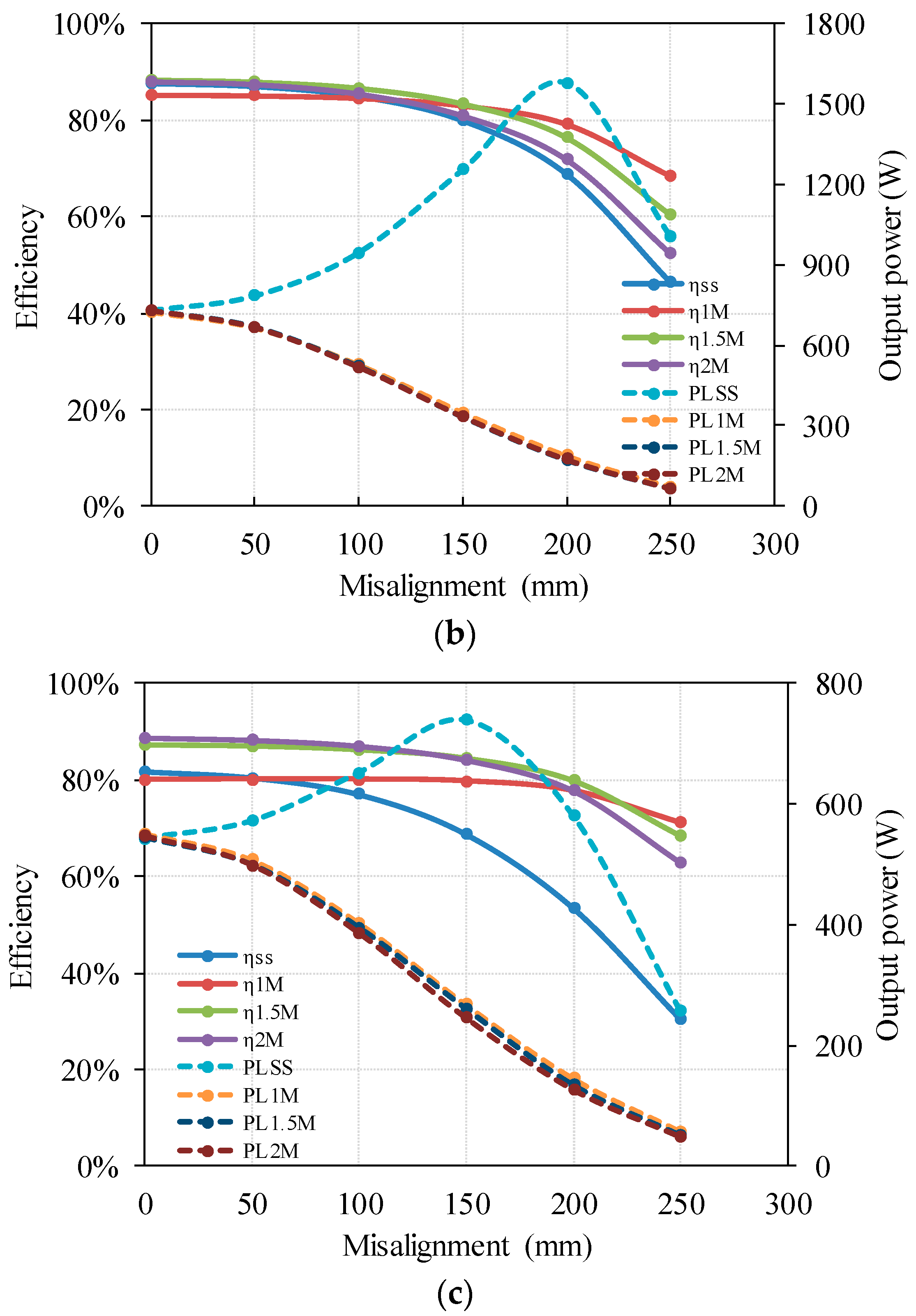
Considering the output power, when the load resistance is small, such as 5 Ω in this simulation, when Lf = M12, the output power of the two systems could be very close to each other. But with the load resistance increasing, a smaller ratio of Lf/M12 is required to achieve the same output power. When the load resistance is too high, such as 200 Ω in this simulation, even the maximum output power of the LCC-WPT system cannot equal the SS-WPT system output power. Therefore, in order to achieve equal output powers for the SS-WPT system and the LCC-WPT system, the DC input voltage must be adjusted.
Regarding the system efficiency, the phenomena is opposite to the output power. When the load resistance is very small, the maximum efficiency of the LCC-WPT system is still lower than the SS-WPT system, and with an increase in Lf, the efficiency of the LCC-WPT system will decrease because of the losses caused by the parasitic resistance in the coil-system, which will occupy a large part of total power in the system. However, with the load resistance increasing, the equal efficiency points move towards a ratio of Lf/M12 = 1. As shown in the simulation results, when the load resistance is 200 Ω, the ratio of Lf/M12 is about 1.3 for the same efficiency of the two WPT systems.
Therefore, if the LCC-WPT system requires high efficiency, Lf should be sufficiently larger than the mutual inductance without sacrificing its power transfer capacity. If the LCC-WPT system needs to improve the power transfer capacity, Lf should be a suitable small value without considering the efficiency.
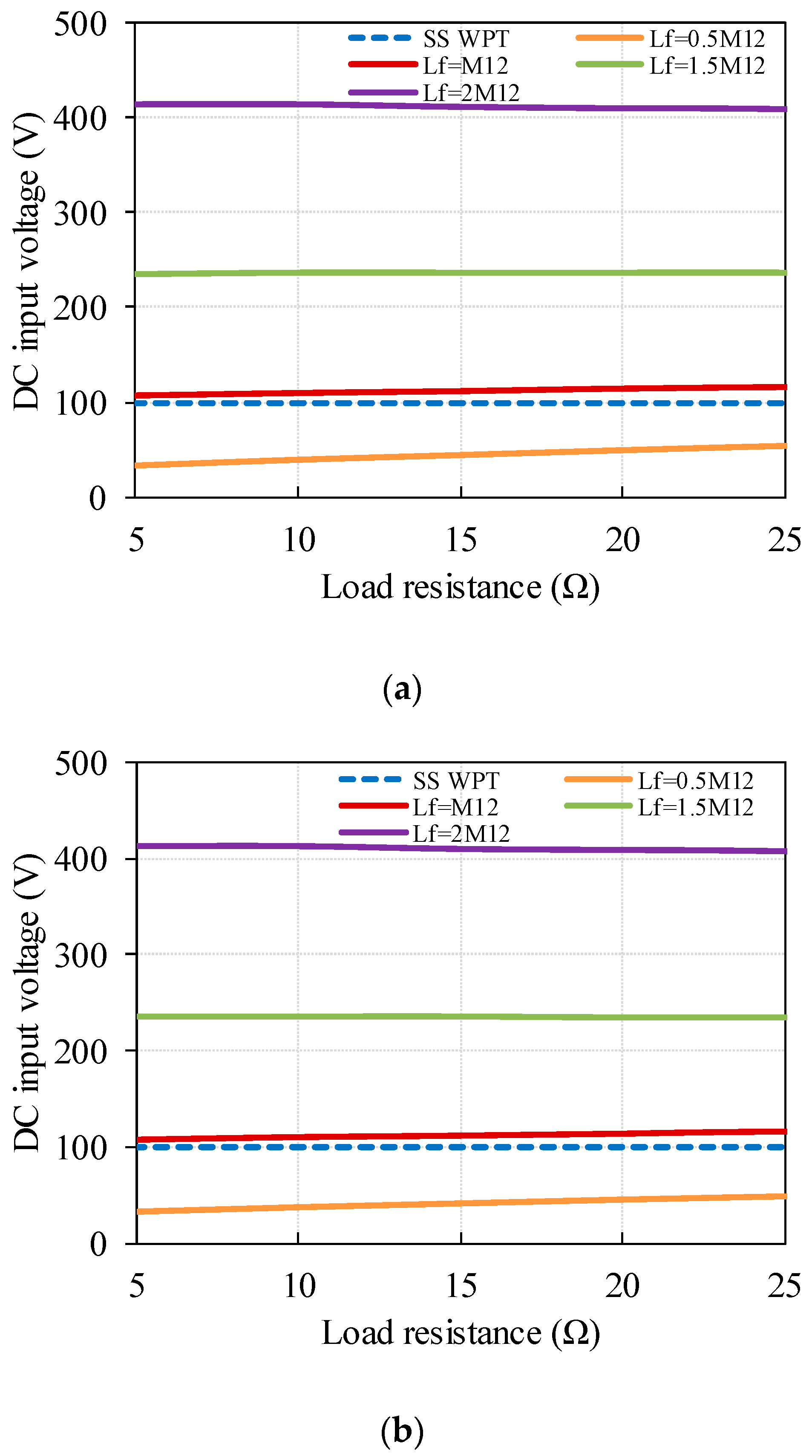
Similar simulations can be carried out to verify the analysis of the DC input voltage tuning method presented in
Section 3.2, when the LCC-WPT system aims at delivering the same power to the same load with the same transmit and receive coils as the SS-WPT system. With the same two assumptions, the results are shown in
Figure 7, containing good consistency with
Figure 5.
In order to investigate why a higher efficiency is possible for the LCC-WPT system, a simulation is made for a particular condition, the results of which are shown in
Table 3. In this simulation, the DC input voltage of the LCC-WPT system in adjusted to achieve the same output power as the SS-WPT system, with a load resistance of 100 Ω, and DC input voltage of the SS-WPT system at 50 V. It can be seen from
Table 3 that when
Lf has a large enough inductance, the LCC-WPT system efficiency will be higher than the SS-WPT system, as the primary side total loss is greatly reduced whilst there is only a relatively small increase in loss in the secondary side. As
Lf/
M12 increases, the load resistance reflected to the input increases, reducing driver current and increasing driving voltage.
From the theoretical analysis and the simulation, it can be seen that one advantage of the SS-WPT system is that it needs fewer components than the LCC-WPT system. But with the LCC-WPT system, from the theoretical analysis and the simulation, it is seen that higher efficiency can be achieved with an optimum choice of Lf. It was also shown in the previous analysis that when Lf changes, the output power of the LCC-WPT system will differ greatly and can be several tens of times that of the SS-WPT system output power with the same DC input voltage. But under this condition, high voltage stresses are placed on system components.
Therefore, in order to investigate at a greater depth the advantages and disadvantages of the SS-WPT system over the LCC-WPT system with various
Lf, and validate the mathematical and simulation analyses conducted previously, a practical SS-WPT system and three LCC-WPT systems with different
Lf designs are constructed, with
Lf set at
M12, 1.5
M12, 2
M12, as the LCC-WPT system is designed for a higher system efficiency than the SS-WPT system, which means the
Lf cannot be smaller than
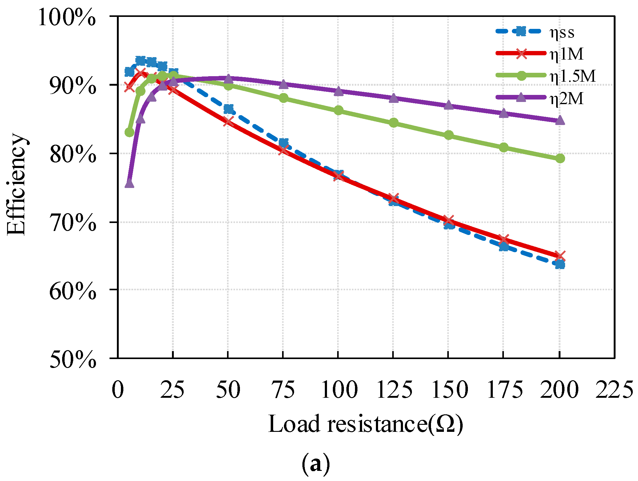
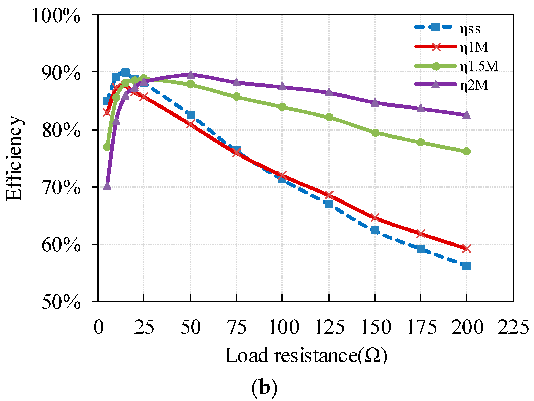
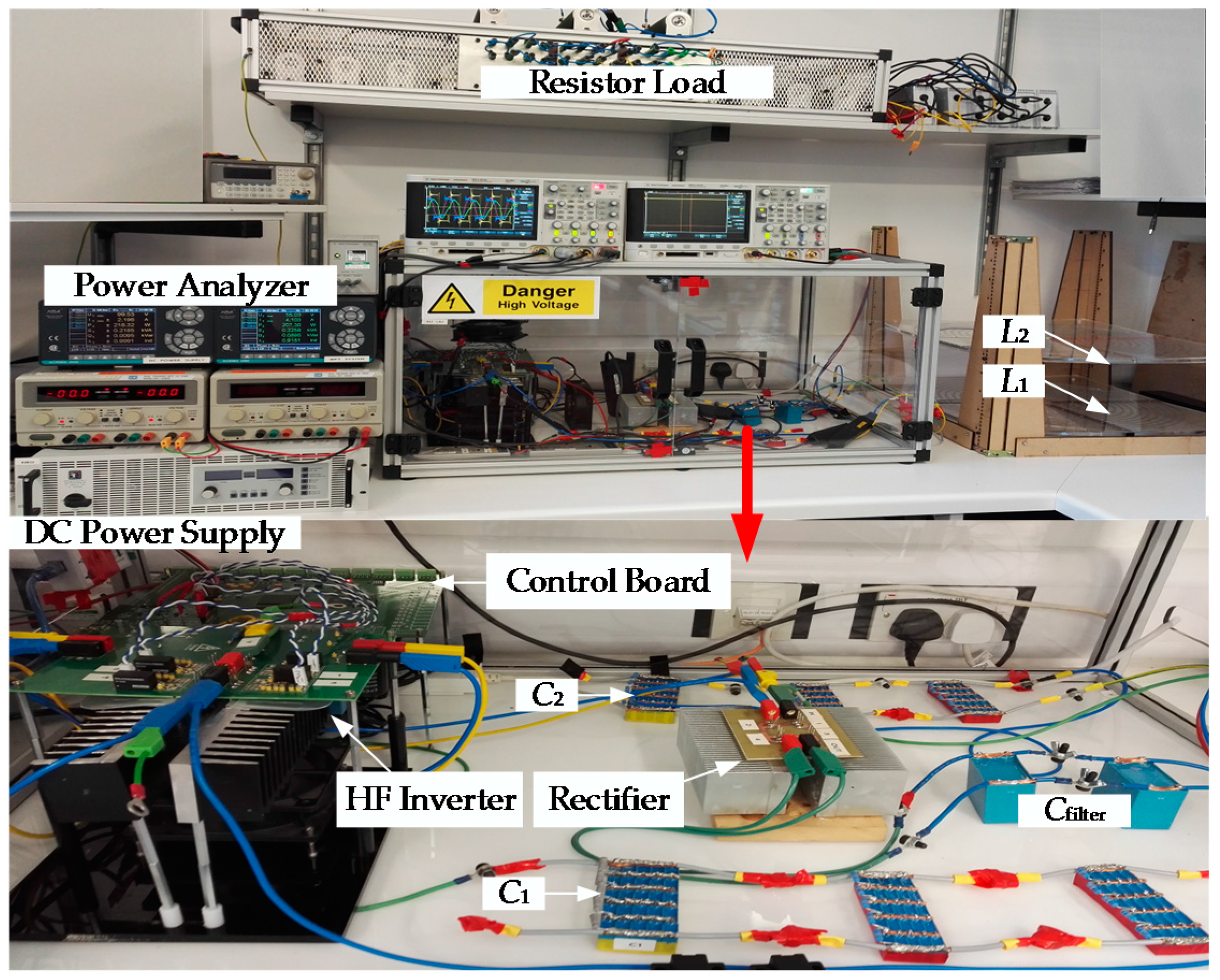
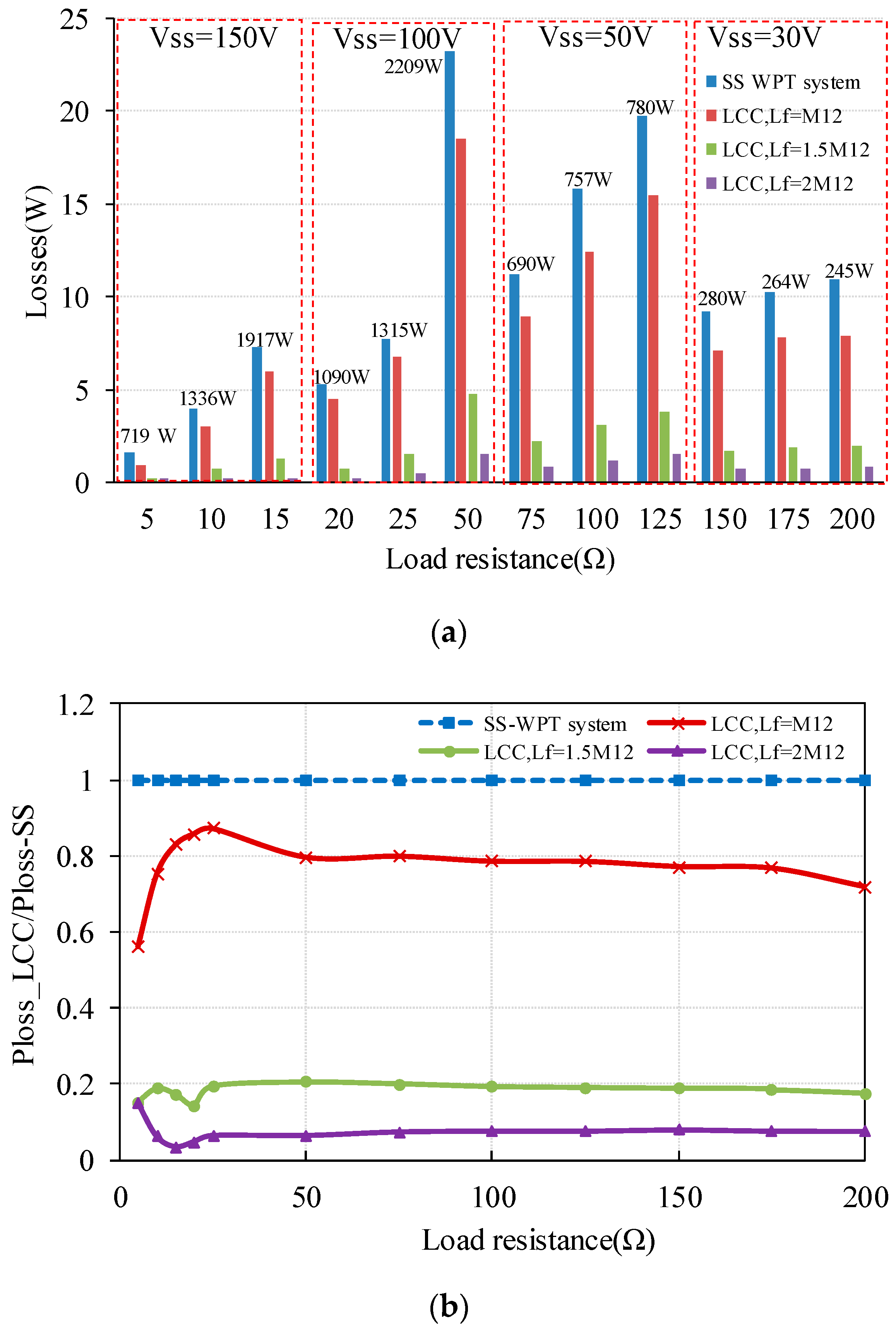
M12, and all the experiments and conclusions are based on this precondition. The LCC-WPT system and the SS-WPT system are compared with various loads resistance values, as load resistance can change the output power of the system without changing other parameters to provide different load conditions. The DC input voltage is adjusted to provide the same output power for the LCC and SS WPT systems. More aspects are analysed in detail with the experimental setup introduced in
Section 4, such as the system efficiency, the maximum voltage stress on components, and the losses in the MOSFETs (metal oxide semiconductor field effect transistor) with various load resistances.


