Optimal Pole Number and Winding Designs for Low Speed–High Torque Synchronous Reluctance Machines
by
 ,
,
Gurutz Artetxe
1,2,* ,
,
Jesus Paredes
1,2,
Borja Prieto
1,2,
Miguel Martinez-Iturralde
1,2 and
Ibon Elosegui
1,2 1
Ceit, Manuel Lardizabal 15, 20018 Donostia/San Sebastián, Spain
2
Tecnun, Universidad de Navarra, Manuel Lardizabal 15, 20018 Donostia/San Sebastián, Spain
*
Author to whom correspondence should be addressed.
Energies 2018, 11(1), 128; https://doi.org/10.3390/en11010128
Submission received: 16 November 2017
/
Revised: 28 December 2017
/
Accepted: 31 December 2017
/
Published: 5 January 2018
(This article belongs to the Special Issue Electric Machines and Drives for Renewable Energy Harvesting 2017)
Abstract
:This paper studies the feasibility of using synchronous reluctance machines (SynRM) for low speed–high torque applications. The challenge lies in obtaining low torque ripple values, high power factor, and, especially, high torque density values, comparable to those of permanent magnet synchronous machines (PMSMs), but without resorting to use permanent magnets. A design and calculation procedure based on multistatic finite element analysis is developed and experimentally validated via a 200 Nm, 160 rpm prototype SynRM. After that, machine designs with different rotor pole and stator slot number combinations are studied, together with different winding types: integral-slot distributed-windings (ISDW), fractional-slot distributed-windings (FSDW) and fractional-slot concentrated-windings (FSCW). Some design criteria for low-speed SynRM are drawn from the results of the study. Finally, a performance comparison between a PMSM and a SynRM is performed for the same application and the conclusions of the study are summarized.
1. Introduction
Permanent magnet synchronous machines (PMSM) are the most widely used machines for low speed–high torque applications. They have the advantage of having a high torque density capability, at the expense of needing large amounts of rare-earth permanent magnets, whose price represents a high percentage of the total cost of the machine.
However, the sudden rise of the price of rare-earth magnets that took place at the beginning of the decade greatly increased the cost of PMSMs. Thus, the interest in other technologies has increased. Among them, the synchronous reluctance machine (SynRM) arises as a good alternative.
Many studies have shown that SynRMs offer several advantages compared to induction machines (IM), such as a higher efficiency and torque density, lower rotor temperature and, potentially, lower price [1,2,3,4]. Some advantages compared to PMSMs are also mentioned: no rotor temperature restriction, better fault-tolerant behavior and lower price [2,5,6,7]. In some applications, SynRMs have been deemed a viable alternative for IMs and even for PMSMs, e.g., in traction or industrial applications [2,3,4,8].
Replacing PMSMs by SynRMs in low speed–high torque applications is especially interesting and challenging. Moreover, using high pole number or FSCWs are common design strategies on PMSMs for these applications, but they are not for SynRMs. Only a few examples for SynRMs can be found in the bibliography [9,10,11,12,13,14,15], but they have not been investigated together, or have evaluated different winding types for a specific application.
Consequently, the objective of this paper is to study the feasibility of SynRMs for low speed applications. For that purpose, firstly a procedure for designing SynRMs is developed and validated by the manufacture and testing of a 200 Nm 160 rpm prototype. Following this procedure, several machines are designed and analyzed to find the optimal pole number and stator slot combinations, together with evaluations of various winding types: fractional-slot concentrated-winding (FSCW), fractional-slot distributed-winding (FSDW) and integral-slot distributed-winding (ISDW).
This paper is organized as follows: first the developed design and calculation procedure is presented in Section 2 and validated in Section 3; in Section 4, the machine specifications and the limits of the study are explained; in Section 5, the results of the studied machines are deeply analyzed and some design criteria are obtained; in Section 6, a SynRM is designed based on the previously obtained design criteria and its performance is compared to that of a PMSM candidate for the same application. Finally, the main conclusions of the study are discussed in Section 7.
2. Design and Calculation Procedure
In this section, a procedure to obtain the full machine definition from the specifications is developed. Algebraic, finite element method (FEM) and automatic optimization methods are used for this. These are developed in a tool generated in MATLAB® that works together with the open source FEM software FEMM®.
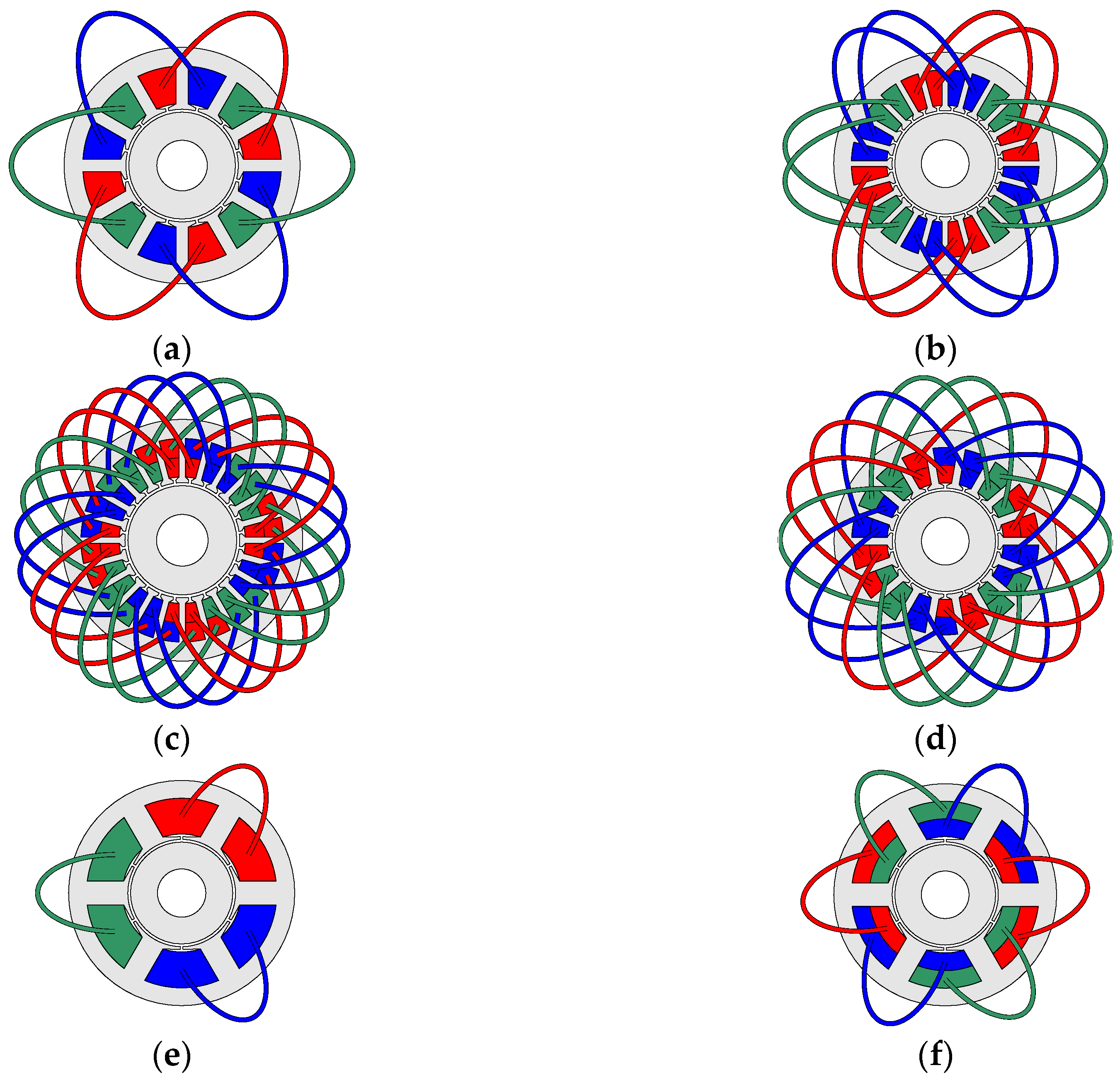
Firstly, the winding configuration is defined. The winding type (ISDW, FSDW or FSCW), the pole pair number (p), the stator slot number (Qs), the slot layer number (nl,w,s) and the short pitching (τa) are chosen by the designer. Some winding configuration examples are shown in Figure 1 for a two-pole pair machine, with different winding types, and thus a different number of slots and winding layers.
Then, the main machine dimensions are calculated based on the sizing Equations (1) and (2) [16]. Air-gap volume (Vagap) and stator current (I) are calculated for a given torque (Mem,ref), speed (ω) and voltage specifications (Un,ref), and other parameters that are imposed based on the designer’s criteria (e.g., electric loading, current density, etc.):
where kω,s1 is the first harmonic winding factor, Aref is the reference electric loading, Bagap,ref is the reference air-gap flux density, PFref the expected power factor and ηe,ref the expected efficiency.
Inner stator diameter and stack length are obtained from the air-gap volume. The needed slot section is calculated based on the stator current, the slot fill factor and the current density. The outer stator diameter and the slot dimensions are obtained from the slot section, so the stator is completely defined.
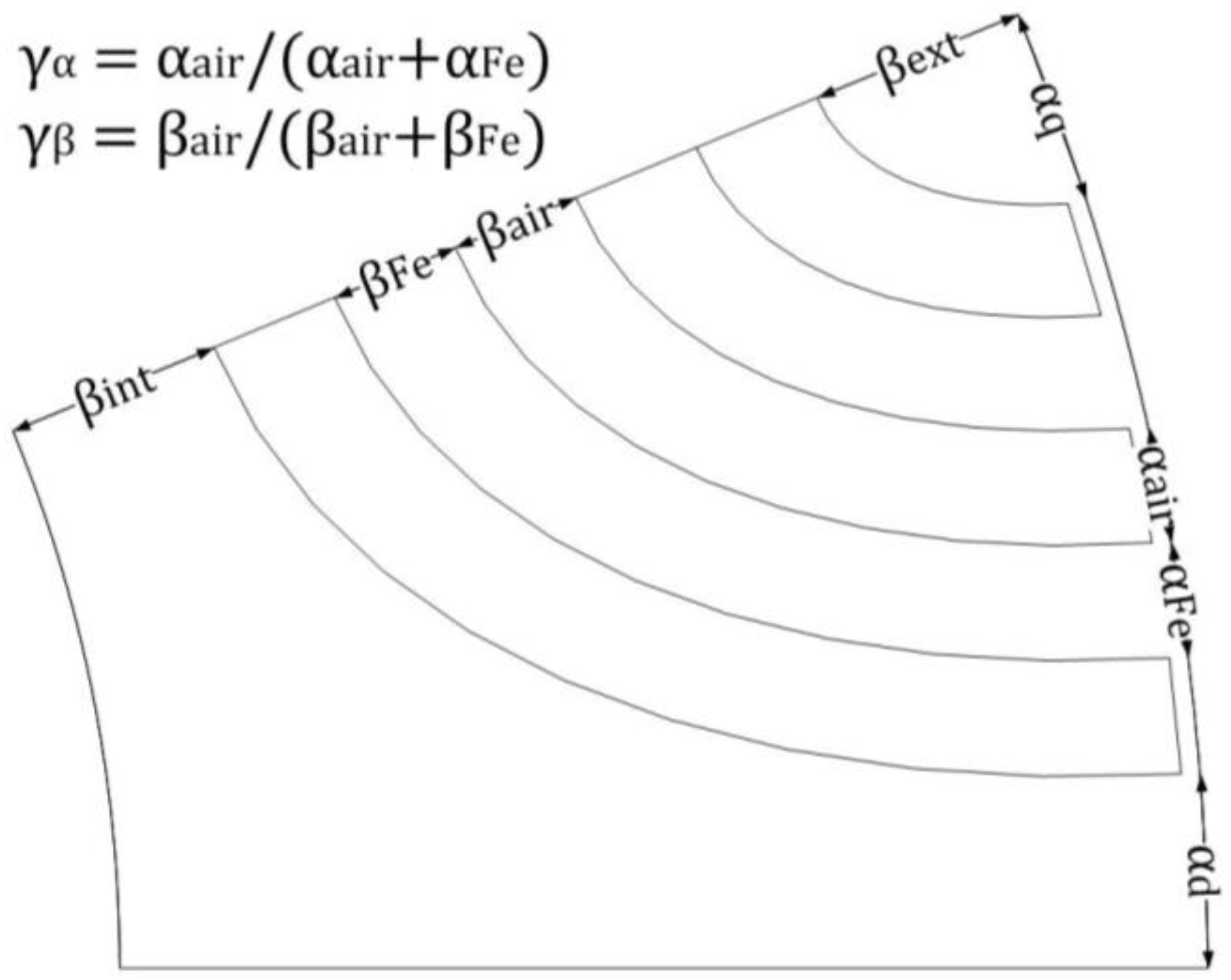
The considered rotor geometry is the one with elliptic-shaped barriers, all of them with the same width (see Figure 2), which has been proven to be a good solution [5,17,18]. αd represents the ratio between the iron arc in the d axes (the arc between the first barrier of two poles at the air-gap) and the polar arc at the air-gap. αq represents the ratio between the iron arc in the q axes (the arc between the two extremes on the last barrier of a pole at the air-gap) and the polar arc at the air-gap. βint refers to the ratio between the inner iron length in the center of the pole (the quadrature axis), and the total rotor height. βext refers to the ratio between the outer iron length in the center of the pole (the quadrature axis), and the total rotor height. γα indicates the portion of the barrier (air) arc for each barrier plus island (iron) arc at the air-gap. γβ indicates the portion of the barrier length for each barrier plus island length in the center of the pole.
The rotor geometry is defined so the air/iron proportion in radial and circumferential directions is constant regardless of the number of poles. Table 1 shows the rotor geometric parameters’ values for the example pre-defined rotor.
With the winding configuration, stator geometry and a pre-defined rotor geometry, the first design of the machine is fully defined.
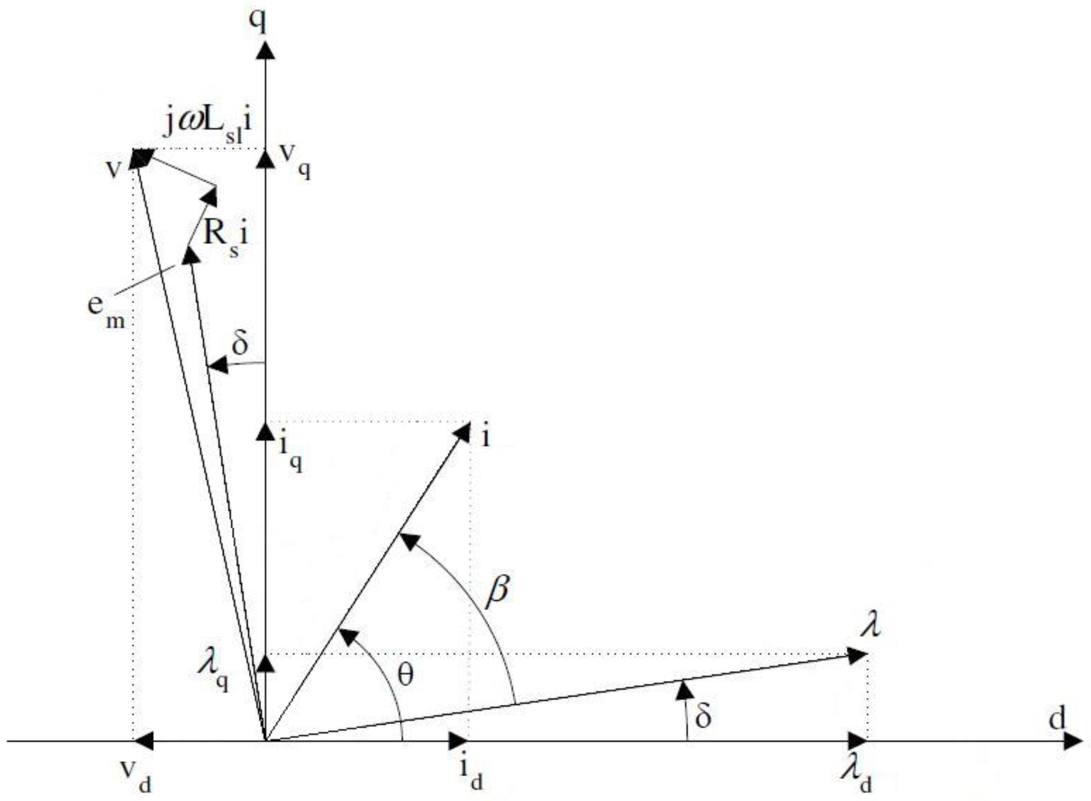
For the completely defined machine, full performance characteristics are calculated with multistatic FEM simulations, where the current angle is calculated by applying the maximum torque per ampere (MTPA) control strategy. The flux linkage and flux densities are obtained from these simulations, and the rest of the machine performance characteristics are calculated based on the SynRM vector diagram, Figure 3, and algebraic formulation, Equations (3)–(6) [19]:
The stator geometry is then modified to meet some reference flux density values. To do so, an iterative optimization process is used to obtain the slot dimensions and the stator outer diameter. The tooth width, the slot height and the yoke height are automatically modified and the machine performance characteristics are calculated in every iteration with the proposed calculation procedure. The final stator geometry is the one that minimizes the difference between target and calculated flux densities. Additionally, the stator phase current is calculated every iteration for the new slot area, the current density and the number of conductors. The number of iterations for a given specification should be between 20 and 25.
3. Validation
A SynRM is designed, manufactured and tested in order to validate the procedure presented in Section 2. The specifications of the designed machine are based on a known PMSM for a hoisting application, shown in Table 3.
The main characteristics of the designed machine are listed in Table 4.
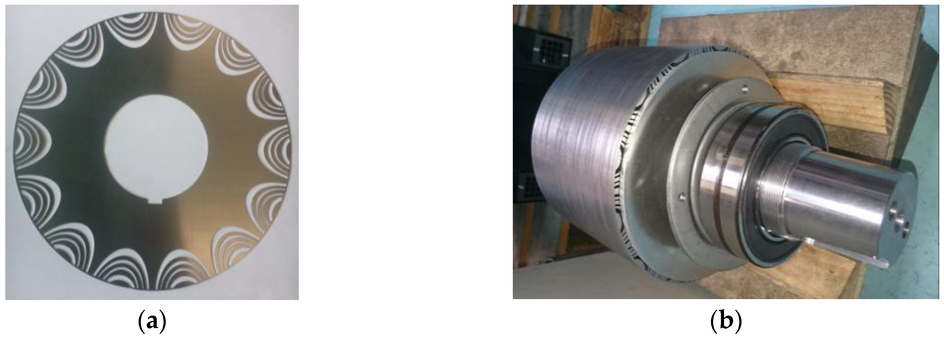
For the manufactured prototype, the geometry of the rotor is optimized based on a multi objective differential evolution (MODE) approach [20,21,22,23,24] in order to maximize the mean torque and reduce the torque ripple, resulting in non-equal barriers, as can be observed in Figure 5, where the rotor lamination and the whole rotor of the prototype are shown.
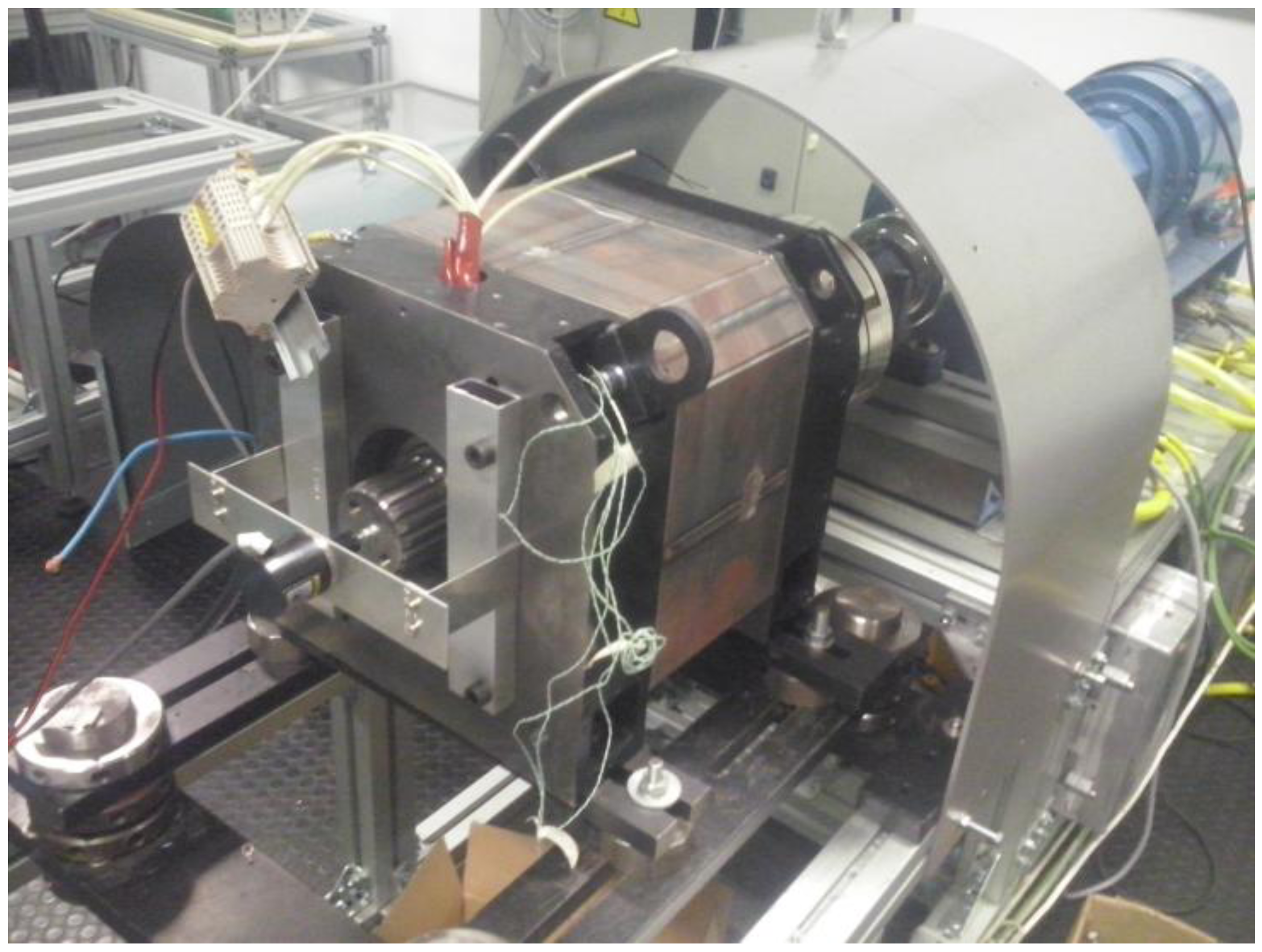
An experimental testing of the prototype machine is carried out, with the setup shown in Figure 6. The main performance characteristics obtained by the developed algebraic–magnetostatic FEM methods and test results are compared in the Table 5.
The difference between both calculation methods is lower than 10% in all of the cases, which proves that the results given by the developed calculation procedure are accurate.
4. Machine Specifications and Limits of the Study
The objective of the performed analysis is to find some pattern that relates the main performance characteristics with the pole number, stator slot number and the winding type. For this purpose, machine designs with different combinations are studied for the same specification.
The specifications and restrictions for which the machines are designed are based on the PMSM for a hoisting application mentioned in Section 3. These are shown in Table 6.
The limits for the studied parameters are the following: pole pair numbers from 4 to 10 have been considered, because high pole number machines are typically used for low speed applications; the maximum stator slot number value has been set to 72, in order to avoid too short slot spans; different short pitching and winding layer values have been considered. Only winding layouts with winding factor values above 0.85 have been considered.
For the sake of focusing on machine parameters related to the winding design, no rotor optimization as for the prototype shown in Figure 6 is carried out for the machines designed and analyzed in this work, the rotor geometry being as defined by the values in Table 1. Rotor geometry optimization via a MODE or similar approach in order to maximize the mean torque and reduce the torque ripple or improve other machine performance metrics should be a necessary subsequent step after the analysis presented in this work.
Following the design procedure of the Section 2, 70 machines with all the possible combinations of the studied parameters have been designed.
5. Results Analysis and Design Criteria
In this section, the results of the 70 machine designs with the pre-defined rotor geometry are shown and analyzed. The main machine performance characteristics consist of mean torque (Mem), torque ripple (Mem,ripple), power factor (PF) and electromagnetic efficiency (ηe). Then, the causes of the obtained results are explained through studies on other parameters such as the saliency ratio (ξ) and the air-gap flux-density waveform (Bagap) among others.
5.1. Mean Torque
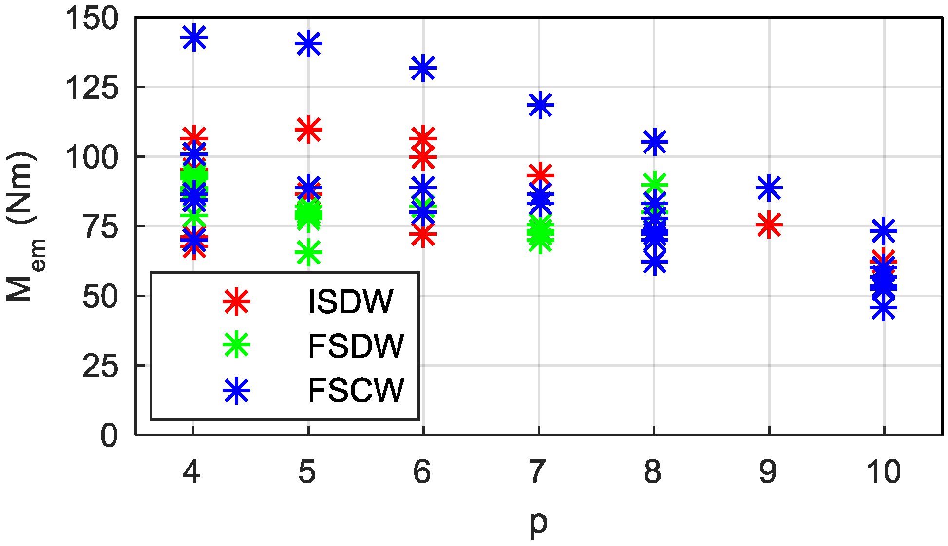
Figure 7 shows the dependency of mean torque (Mem) on the pole pair number and the winding type. Each dot in the graph represents the result of a single machine. Different winding types are plotted with different colors. Different dots with the same pole number and winding type correspond to the results of machines with different stator slot number, winding layer or short pitching values.
As can be seen in Figure 7, the first conclusion is that, with the same volume, none of the SynRM designs meet the mean torque specification.
There is an influence of pole number on the mean torque: the lower the pole number, the greater the mean torque. Upon analyzing the influence of the winding type on the mean torque, it is found that the machines with the highest mean torque values for each pole number are obtained by FSCW machines. For the rest of the FSCW machines, the mean torque values are comparable to those obtained with FSDW and ISDW machines.
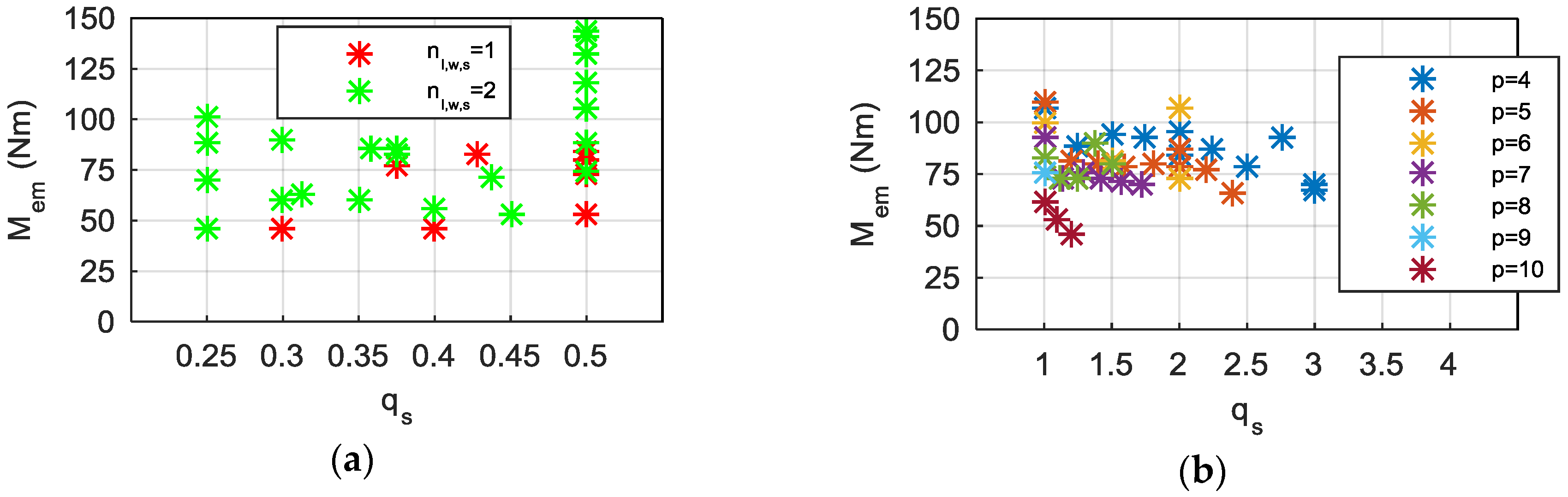
If the machines with FSCW are further analyzed, it can be observed that the combinations that lead to the highest mean torque values correspond to double layer slot windings (nl,w,s = 2) with 3 slots per pole pair (qs = 0.5), Figure 8a. The dots represent the mean torque results of all the FSCW machines. The obtained results for different slot layer numbers are plotted with different colors.
Among the machines with distributed winding (i.e., ISDW and FSDW), the highest mean torque values for the same pole number are obtained for one slot per pole and phase (qs = 1), Figure 8b.
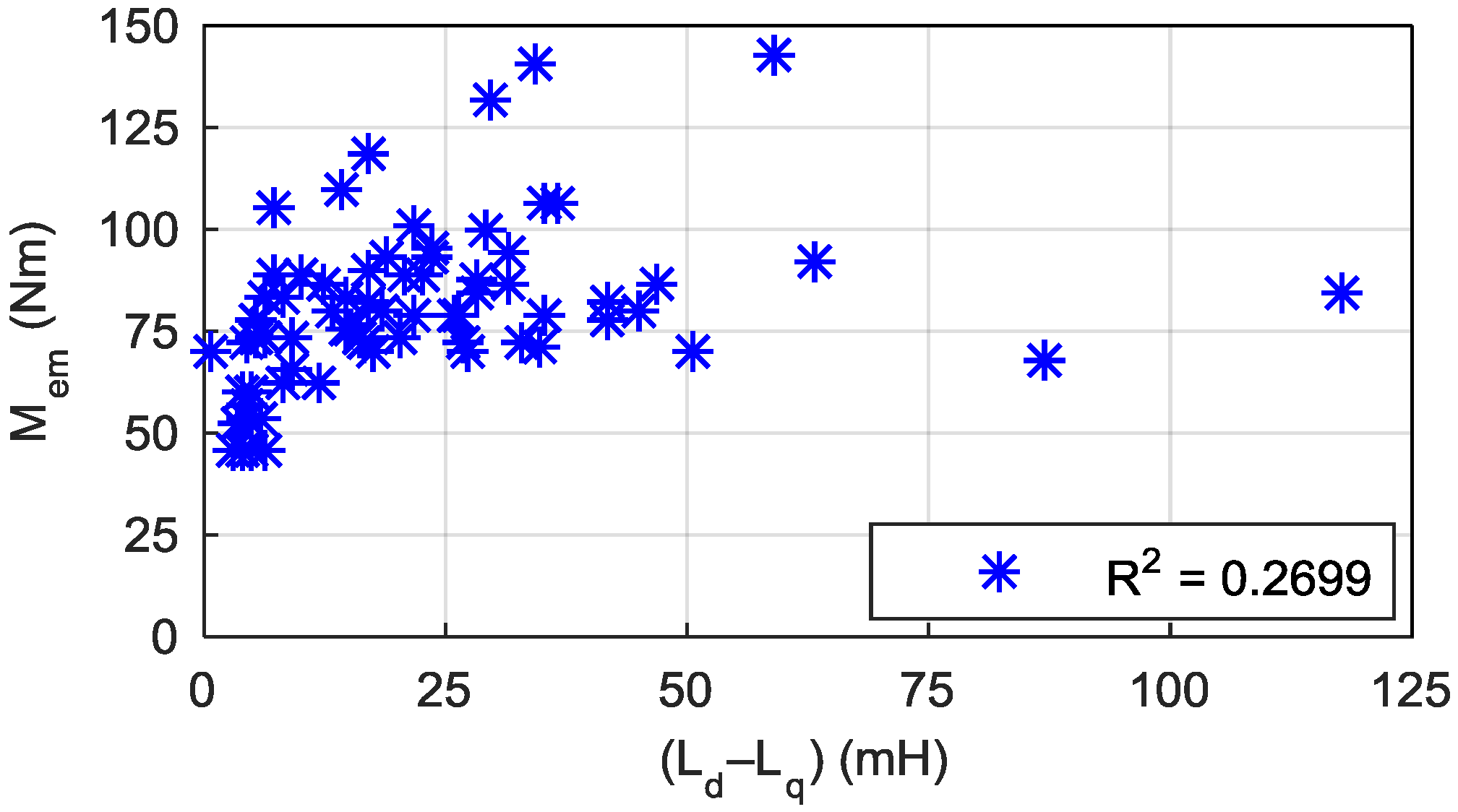
Although the torque capability is related to the difference between direct and quadrature inductances (Ld − Lq) [1,2,8], the correlation between the studied variable (Ld − Lq) and the objective variable (Mem) for the studied machines is weak (Figure 9). The correlation is analyzed using the coefficient of determination, or R2 value, of the least squares regression. Linear or quadratic functions have been considered depending on the data series shape. R2 ranges from 0 to 1, being 0 no correlation and 1 perfect correlation.
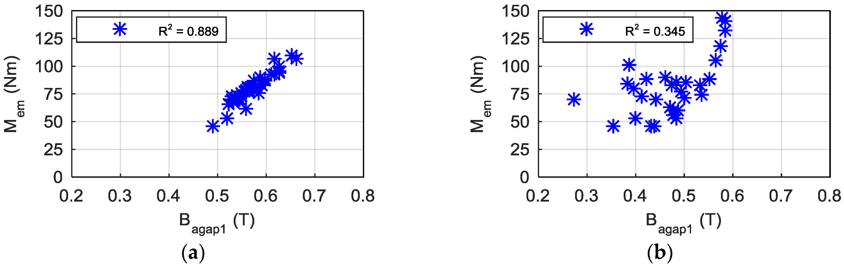
Another parameter related to the torque capability is the air-gap flux density (Bagap). Figure 10a,b shows the relation between the first harmonic of the air-gap flux density (Bagap1) and the mean torque for the machines with distributed and concentrated windings, respectively. For the distributed winding machines a strong correlation exists: higher first harmonic air-gap flux density values lead to higher mean torque values. The correlation is not clear for concentrated winding machines.
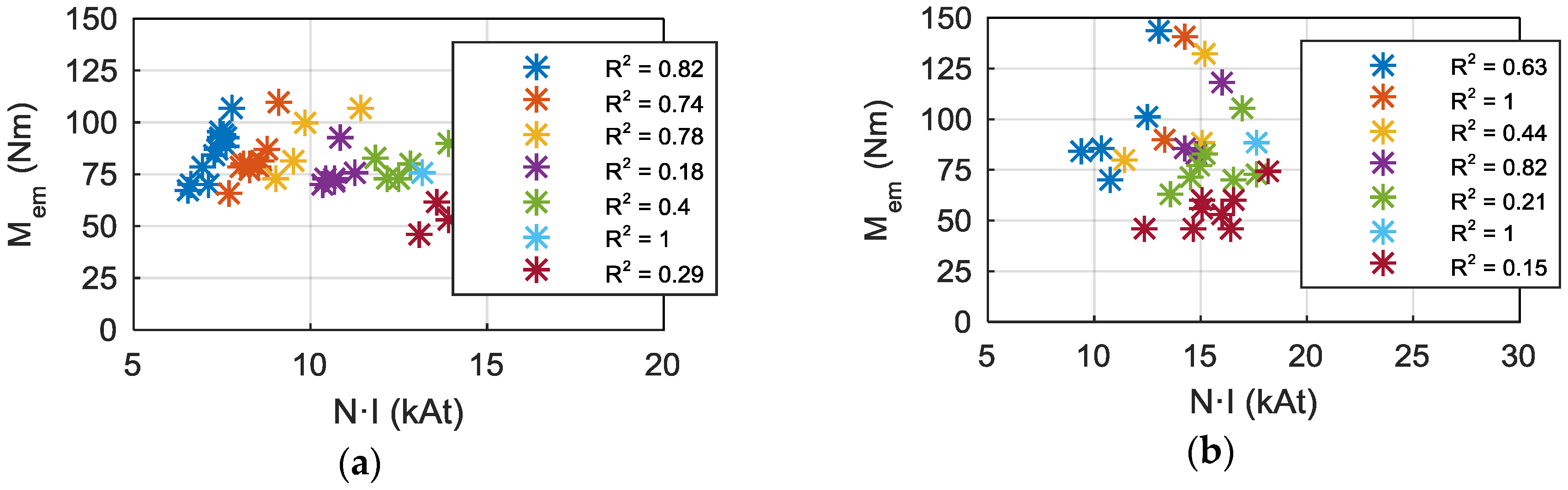
Going deeper into the torque capability study, another parameter related to the air-gap flux density is studied: the magnetomotive force (N·I), N being the number of series turns per phase. Figure 11a,b shows the relation between the magnetomotive force and the mean torque for the machines with distributed and concentrated windings, respectively. The R2 values for each pole pair data group are shown, from p = 4 to p = 10. Note that data series with one or two machines will always have R2 = 1 value.
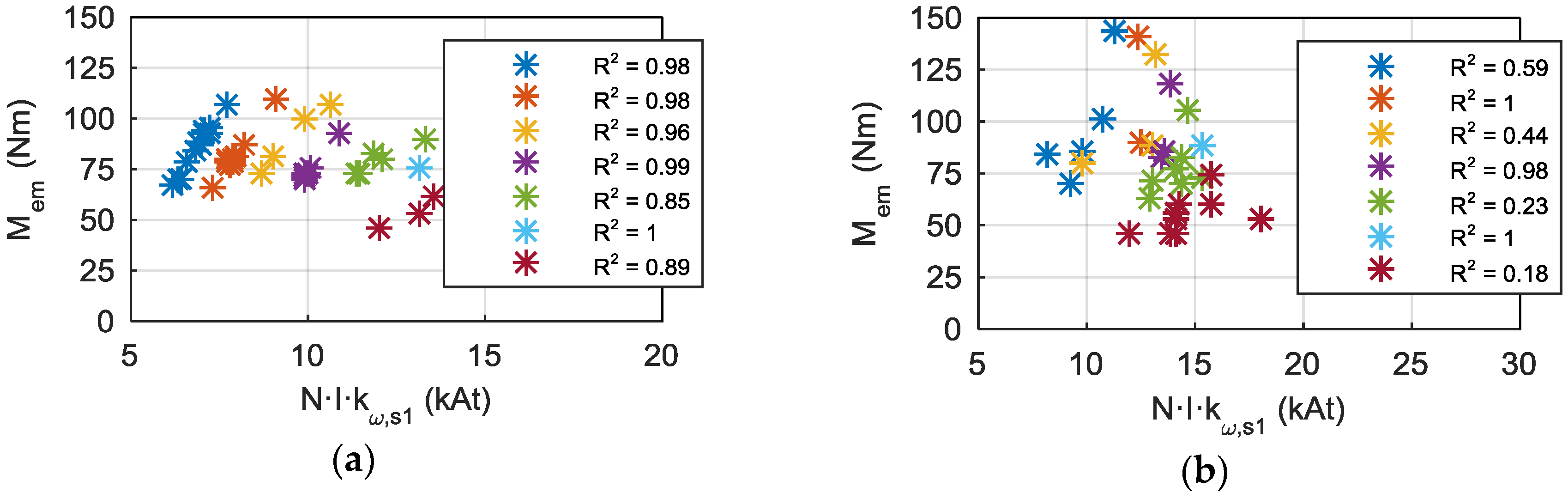
The relation between the mean torque and the magnetomotive force is more direct if the first harmonic winding factor (kω,s1) is taken into account. Figure 12a,b shows the relation between the mean torque and N·I·kω,s1 for the machines with distributed and concentrated windings respectively. The adjustment values show that there is a strong correlation for the distributed winding machines, but not in the case of concentrated winding machines.
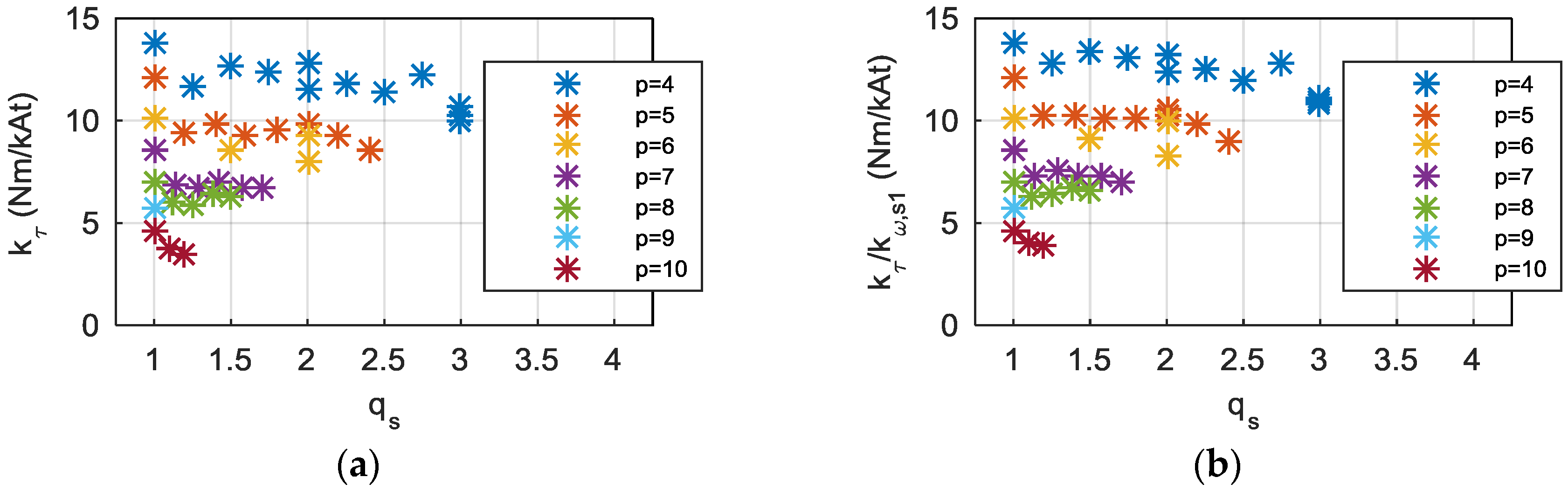
The relation between the mean torque and the magnetomotive force is defined as the torque constant, kT = Mem/(N·I). Figure 11a and Figure 12a shows that the torque constant value is almost constant for the machines with distributed windings and the same pole number. Moreover, the higher the pole number, the lower the torque constant is. The Figure 13a plots the dependency of the torque constant (kτ) on the stator slot number per pole and phase, and the pole pair number for the distributed winding machines. Figure 13b plots the dependency of the torque constant divided by the first harmonic winding factor (kτ/kω,s1) on the same parameters. On the one hand, it can clearly be seen that the dependency on the pole number is high. On the other hand, the stator slot number per pole and phase has its influence: the higher the stator slot number, the lower the torque constant. Attending to Figure 13a, this effect can be explained by the influence of the winding factor. Nevertheless, Figure 13b shows that it is not the only factor explaining this trend. In any case, a low stator slot number is recommended beyond the effect of the winding factor.
The main conclusions of this subsection are summarized below:
- Low pole numbers are recommended due to their high torque constant;
- Distributed winding machines have higher torque constant and winding factor than concentrated winding machines. However, concentrated winding machines allow a higher slot fill factor, so overall torque capability is similar to distributed winding machines;
- Concentrated winding machines with qs = 0.5 and nl,w,s = 2 have the highest torque capability. Mean torque is considerably higher than the rest of the machines;
- Among distributed winding machines, low stator slot number are recommended for their high torque constant. The cases with qs = 1 have the highest torque capability among distributed winding machines.
5.2. Torque Ripple
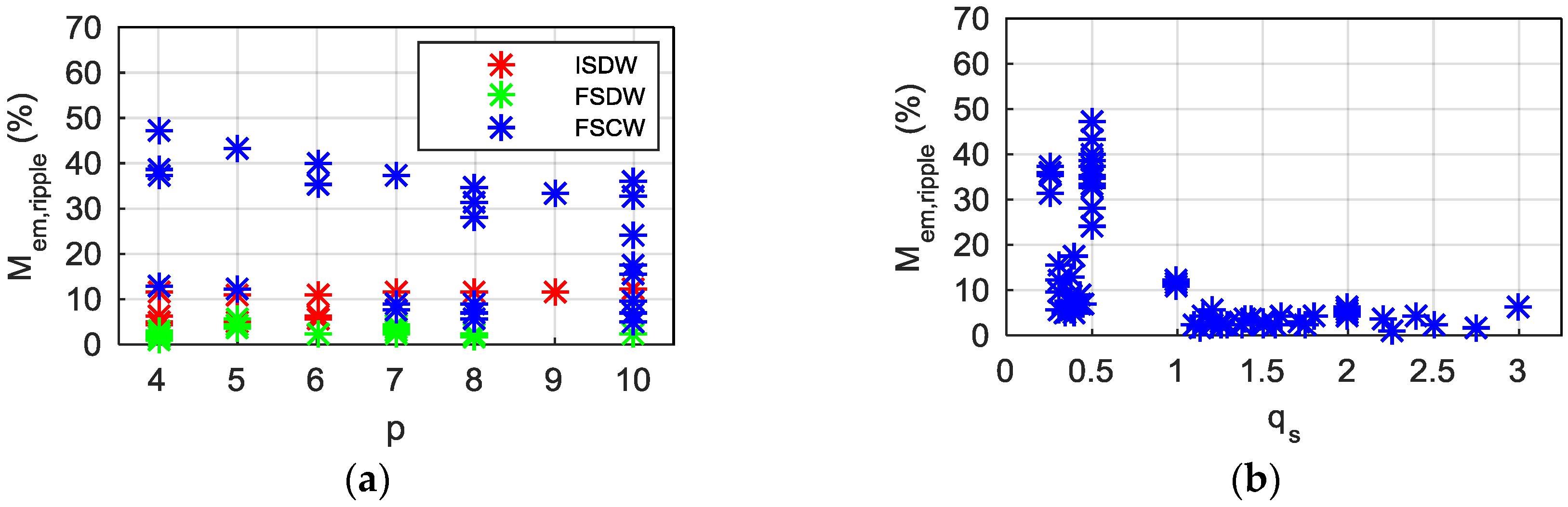
Regarding the torque ripple, Figure 14a shows the dependency of torque ripple (Mem,ripple) on the pole pair number and the winding type, and Figure 14b on the stator slot number. It can be seen that the pole number has no influence on the torque ripple, while the winding type and the stator slot number have a great influence. The lower ripple values are obtained with FSDWs, closely followed by ISDWs, while FSCWs obtain high torque ripple values.
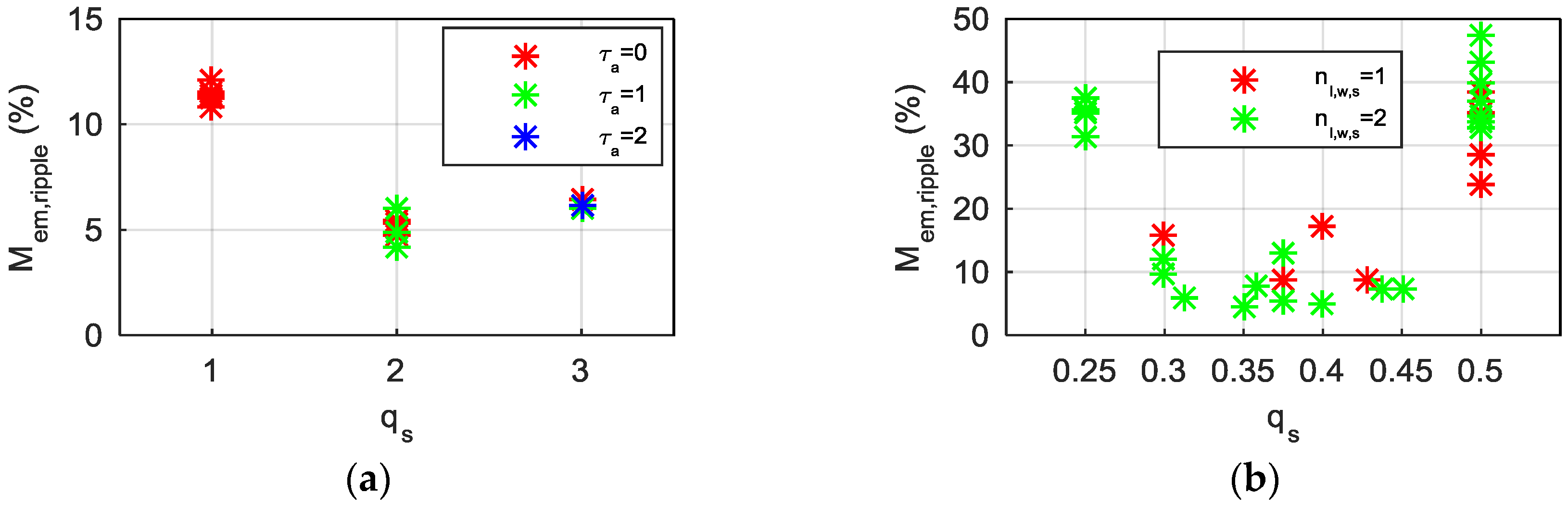
ISDW machines deserve further study of the torque ripple. Figure 15a shows the torque ripple results for ISDW machines with different stator slot numbers per pole and phase and short pitching values. It can be seen that lower torque ripple values are obtained when stator slot number per pole and per phase is greater than unity (qs > 1). In these cases, the torque ripple values are comparable to FSDW machines’ values. Moreover, the short pitching has almost no influence on the torque ripple.
Returning to the FSCW machines, Figure 15b shows the torque ripple for all the concentrated winding machines depending on the stator slot number per pole and phase and slot layer number. Previously, Figure 8 has shown that the ones with double layer windings and qs = 0.5 are the combinations with highest mean torque values. In Figure 15b, it can be seen that they are simultaneously the ones with the highest torque ripple values.
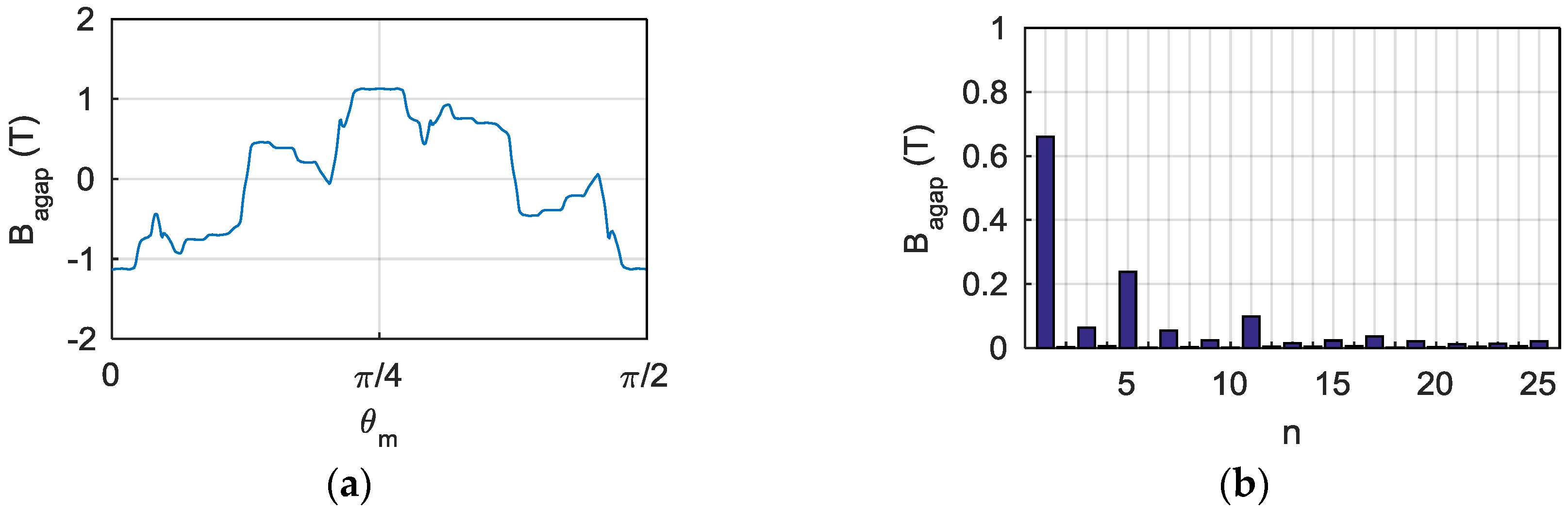
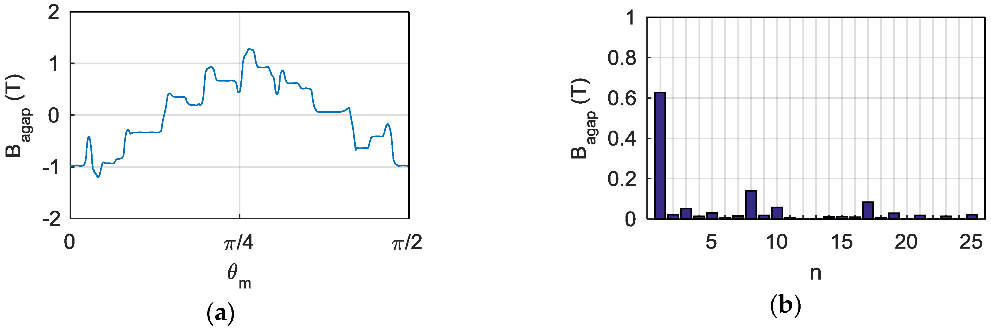
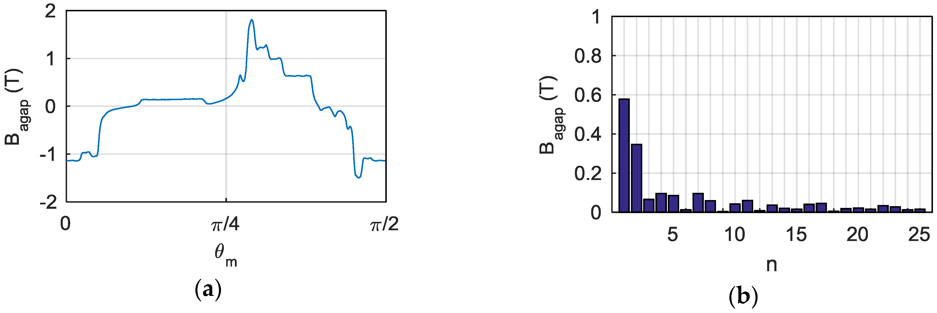
If the causes of the torque ripple are studied, the origin of the torque ripple in SynRMs is in the content of harmonics of the air-gap flux-density waveform (Bagap), which are mainly caused by the relative position between stator and rotor slots and barriers, and the stator magnetomotive force waveform. Air-gap flux-density waveforms and their harmonic spectrum for three machines are shown below: the machine in Figure 16 is a four-pole, 24-stator slot ISDW machine, with a torque ripple of 11.6%; the one in Figure 17 is a four-pole, 36-stator slot FSDW machine, with a torque ripple of 2.9%; the other one, in Figure 18, is a four-pole, 12-stator slot, double layer FSCW machine, with a torque ripple of 47.2%.
As can be observed in Figure 16, Figure 17 and Figure 18, the ISDW and FSDW machines have more sinusoidal shaped waveforms compared to the FSCW machine’s waveform. Moreover, the harmonic content for the FSCW machine air-gap flux-density waveform is proven to be greater than for the other machines.
Considering that all the machines with the same pole number have exactly the same rotor geometry, it can be stated that the differences between the machines is caused by the waveform of magnetomotive force created in the stator.
The magnetomotive force created by FSDW machines is very sinusoidal, and have high order and low amplitude harmonics. Thus, the overall harmonic content is very low, and so is the torque ripple.
ISDW machines with one stator slot per pole pair and phase have fifth and seventh order harmonics with a considerable amplitude, and lower amplitude 11–13 and 17–19 order harmonics. When the number of stator slot per pole pair and phase is higher, the 5–7 harmonics are considerably reduced. The harmonic content for ISDW machines with stator slot number higher than the unity is low enough to ensure low torque ripple values.
In the case of FSCW machines, low order and high amplitude magnetomotive force harmonics are produced. Moreover, the open slots of these machines lead to a negative effect on the torque ripple. In the case of machines with three stator slots per pole (qs = 0.5), 2–4 order harmonics are produced. The great amplitude of the second harmonic produces a very detrimental effect on the torque ripple.
The main conclusions of this subsection are summarized below:
- The pole number has no effect on the torque ripple;
- The winding type and the stator slot number per pole and phase have a great influence on the torque ripple, due to their effect on the magnetomotive force waveform and its harmonic content (Figure 16, Figure 17 and Figure 18).
- ○
- FSDW machines obtain very low torque ripple results, due to their low magnetomotive force harmonic content;
- ○
- ISDW machines obtain low torque ripple results, due to their relatively low magnetomotive force harmonic content. When the number of stator slots per pole and phase is greater than unity (qs > 1), the torque ripple is especially low, because the 5–7 order harmonics are removed;
- ○
- FSCW machines obtain high torque ripple results, especially when three stator slots per pole are used (qs = 0.5), due to their high magnetomotive force harmonic content and slot opening effect.
5.3. Power Factor
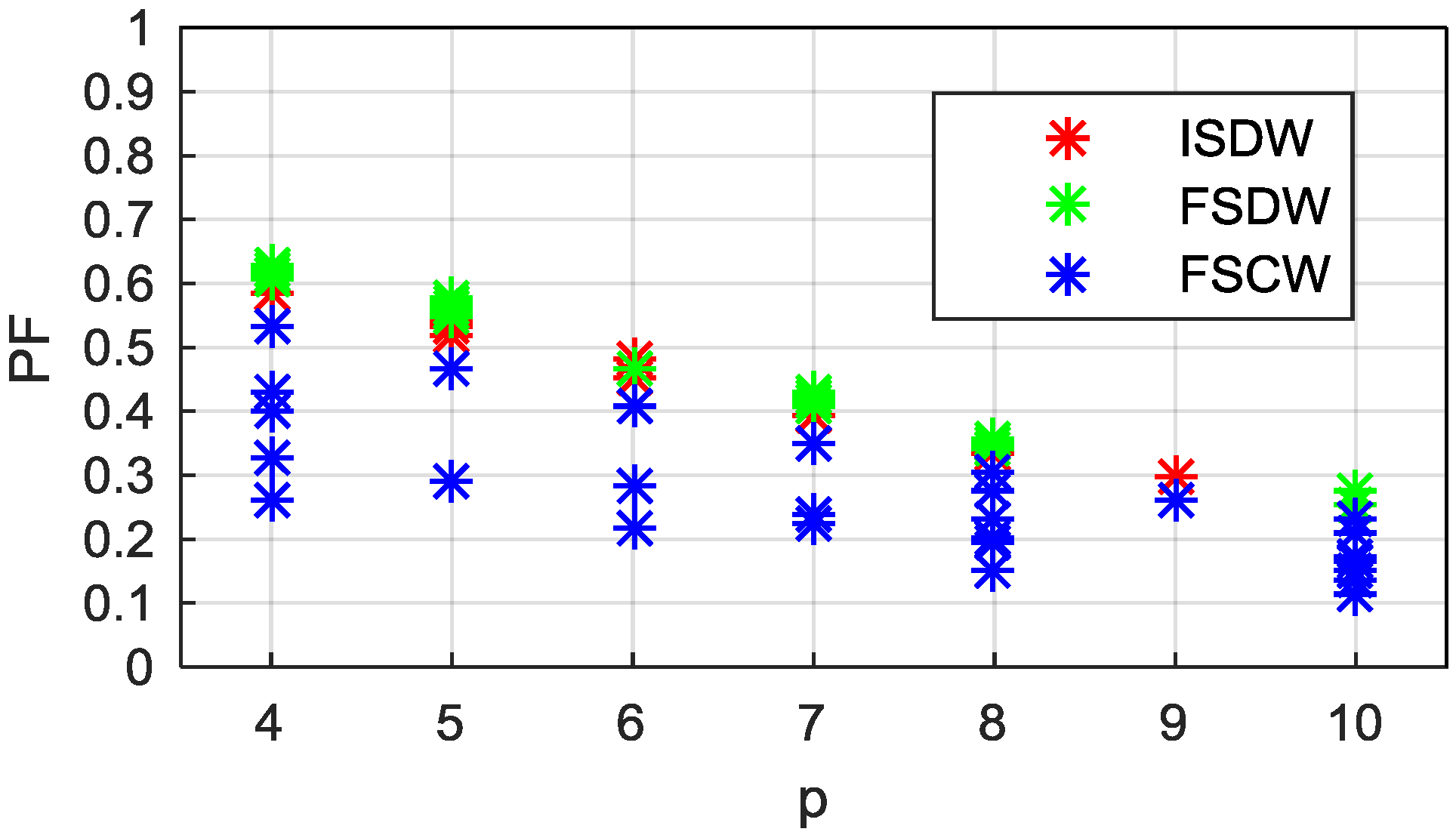
Concerning the power factor (PF), Figure 19 shows its dependency on the pole pair number and the winding type. It can be seen that both pole number and winding type have an evident influence. On the one hand, the influence of the pole number shows that better power factor results are obtained with lower pole numbers. On the other hand, ISDW and FSDW machines obtain better power factor results than FSCW machines.
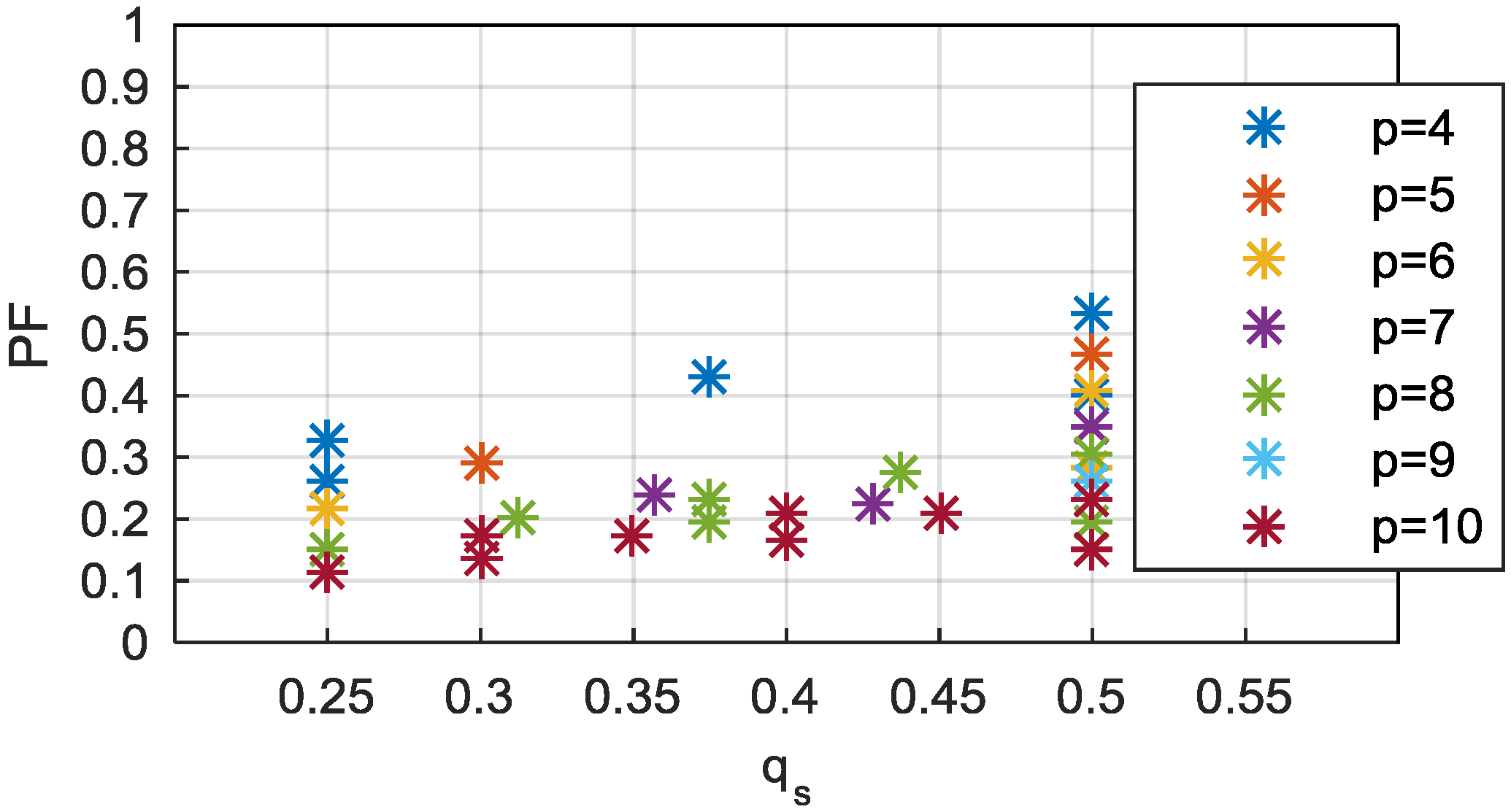
Figure 20 is presented for a deeper study of the FSCW machines. The power factor for FSCW machines for different stator slot number per pole and phase, and pole pair number is plotted. Again, it can be seen that the combinations that lead to the highest power factor values (for the same pole number) correspond to double layer slot windings (nl,w,s = 2) with three stator slots per pole (qs = 0.5). In these cases, the power factor values are slightly lower than those of ISDW and FSDW machines. The rest of the concentrated winding machines obtain appreciably lower power factor values.
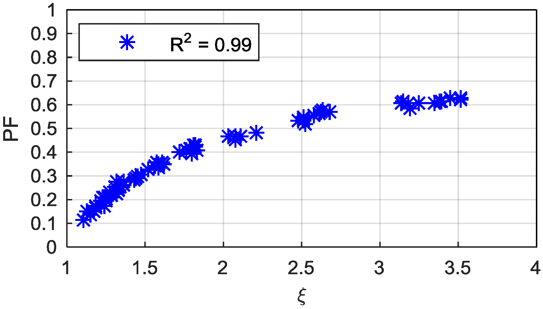
If the causes behind the power factor results are going to be studied, it is necessary to analyze the saliency ratio (ξ). The relation of the power factor with the saliency ratio has been clearly demonstrated in the literature [1,8,15,25,26]. Figure 21 shows that the correlation for the machines considered in this work is strong, and confirms that higher saliency ratios provide higher power factor results independently of the winding type and pole number.
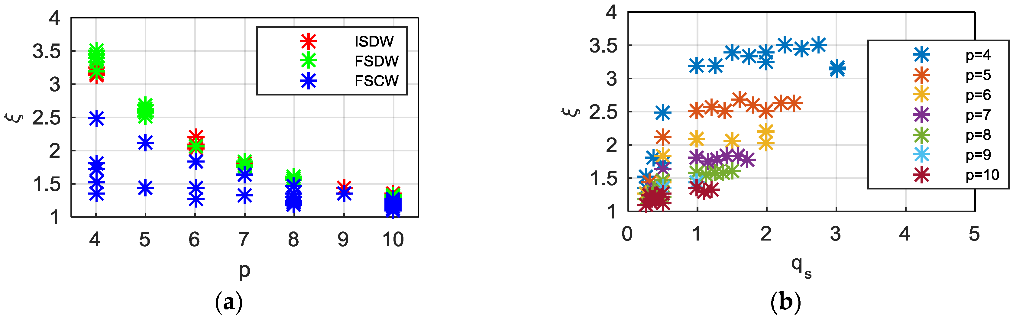
In addition, the relationship of the pole number with the saliency ratio has also been demonstrated by many authors in the literature [3,25]. Figure 22a shows the dependency of the saliency ratio on the pole pair number and the winding type. It can be seen that the lower the pole number, the higher the saliency ratio, and consequently higher power factor values are obtained, as shown in Figure 21. Moreover, the influence of the winding type on the saliency ratio can clearly be observed in Figure 22b: the highest saliency ratios are obtained with FSDW and ISDW machines; noticeably worse saliency ratios are obtained with FSCW machines.
The main conclusions of this subsection are summarized below:
- The pole number has a great influence on the power factor. Low pole numbers are recommended due to their high saliency ratios;
- Distributed winding machines have higher saliency ratios than concentrated winding machines. Among concentrated winding machines, the ones with qs = 0.5 and nl,w,s = 2 have the highest saliency ratios.
5.4. Efficiency
Finally, the electromagnetic efficiency (ηe) is studied. Due to the calculation procedure’s simplifications, only electromagnetic losses are considered in this work (i.e., copper losses (PCu) and iron losses (PFe)).
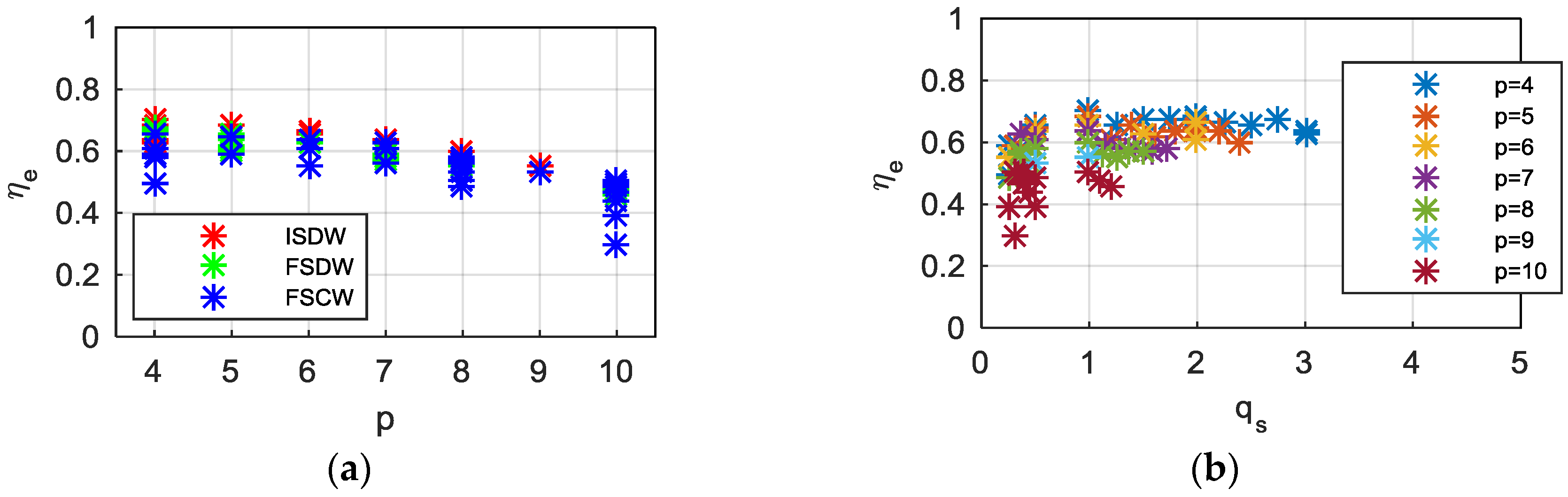
The dependency of the efficiency on the pole pair number and the winding type is shown in Figure 23a. The influence of the pole number shows that better efficiency results are obtained with low pole numbers. The influence of the winding type is not that clear, but it can be seen that in most cases the FSCW machines obtain lower efficiency results.
Figure 23b shows the dependency of the efficiency on the stator slot number per pole and phase, and the pole pair number. It can be seen that the higher efficiency values for each pole number are obtained with ISDW machines with one stator slot per pole and per phase (qs = 1). In general terms, distributed winding machines obtain higher efficiency results than concentrated winding machines.
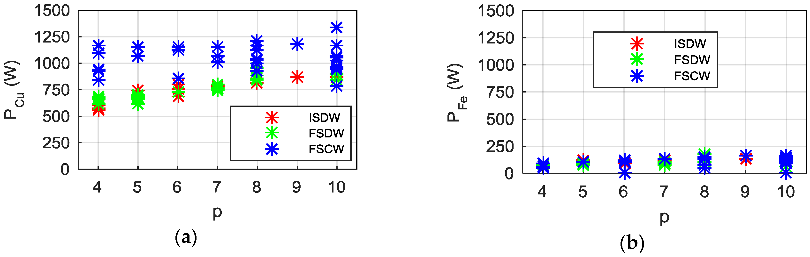
The efficiency of the machines depends on the losses and the output power. Since the speed for all the machines is constant, the output power exclusively depends on the mean torque. Thus, the efficiency is studied with the mean electromagnetic torque, copper losses and iron losses. The Figure 24 shows the copper losses (a) and the iron losses (b) for different pole pair number and winding types.
The iron losses depend on the pole pair number, as Figure 24b shows, due to is dependency on frequency. In any case, the iron losses are considerably lower than copper losses, so the attention in this study must focus on the copper losses.
Since the current density is set, the copper losses mainly depend on the total slot area of the machines and the stator slot fill factor. This explains why concentrated winding machines have higher copper losses, while distributed winding machines have similar copper losses, as it can be seen in the Figure 24a.
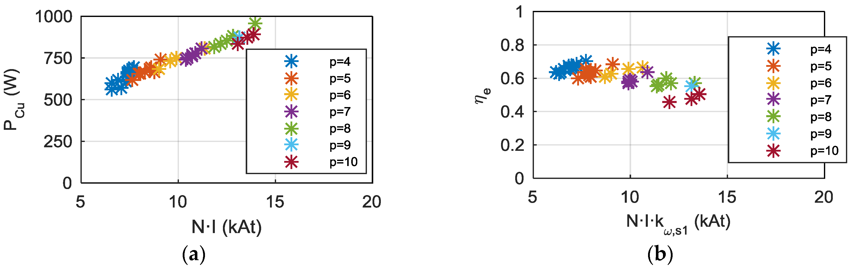
The Figure 25a shows the relationship between the magnetomotive force (which depends on the slot area and the fill factor, in the same way as the copper losses), and the copper losses for the distributed winding machines, depending on the pole pair number. It can be seen that the copper losses are proportional to the magnetomotive force for the machines with the same pole number. The difference between different pole numbers lies in the losses produced in the end windings: the higher the pole number, the lower the end winding length.
It has been proved in Section 5.1 that the mean torque is also proportional to the magnetomotive force (especially if the effect of the winding factor is taken into account, as in Figure 12). Thus, high magnetomotive force values obtain both high mean torque and copper losses. Figure 25b shows the relation between the magnetomotive force, multiplied by the winding factor (N·I·kω,s1) and the electromagnetic efficiency. It is proved that, for the same pole number, machines with higher N·I·kω,s1 values obtain higher efficiency results.
The main conclusions of this subsection are summarized below:
- A low pole number is recommended to obtain a higher efficiency, because they can produce higher output powers with similar losses;
- The winding type has a considerable effect on the efficiency.
- ○
- Distributed winding machines have higher efficiencies than concentrated winding machines;
- ○
- Concentrated winding machines have both, lower torque production and higher losses, in general;
- ○
- Among concentrated winding machines, the ones with qs = 0.5 and nl,w,s = 2 have efficiencies comparable to distributed winding machines.
5.5. Design Criteria
Based on the conclusions of the analysis, the main key steps for a good SynRM design are summarized in this subsection. Then, the feasibility of using SynRMs for low speed applications is studied.
The conclusions of the main parameters studied in this work (i.e., pole number, stator slot number per pole and phase, and the winding type) show that:
- On the one hand, a low pole number is recommended for high mean torque, power factor and efficiency. On the other hand, the pole number has negligible effect on the torque ripple;
- ISDW machines have good torque capability, efficiency and power factor. The torque capability and efficiency are especially high when one stator slot per pole and phase is used (qs = 1), but the torque ripple is considerable. Very low torque ripple values are obtained when the number of stator slots per pole and phase is greater than the unity (qs > 1), although it must be noted that further design measures to reduce the torque ripple have not been considered;
- FSDW machines exhibit satisfying torque capability, power factor and efficiency and excellent torque ripples;
- FSCW machines, in most cases lead to moderate torque capability and poor torque ripple, power factor and efficiency results.
- ○
- Among fractional slot concentrated winding machines, the ones with qs = 0.5 and nl,w,s = 2 show excellent torque capability and efficiency. The power factor for these machines is slightly lower than for distributed winding machines and the torque ripple is very high.
In addition to the design criteria related to the main studied parameters, some other aspects must be taken into account:
- The rotor geometry has not been studied in this work, although the literature has demonstrated that it has a deep effect on the torque ripple and the saliency ratio;
- The mean torque of the machines has proven to be linearly related to the air-gap flux density first harmonic. Design strategies that lead to higher air-gap flux densities are recommended, such as the reduction of the air-gap thickness.
6. PMSM vs. SynRM Comparison
In this section, a SynRM is designed based on the previously shown design criteria and the results are compared to those of the original PMSM.
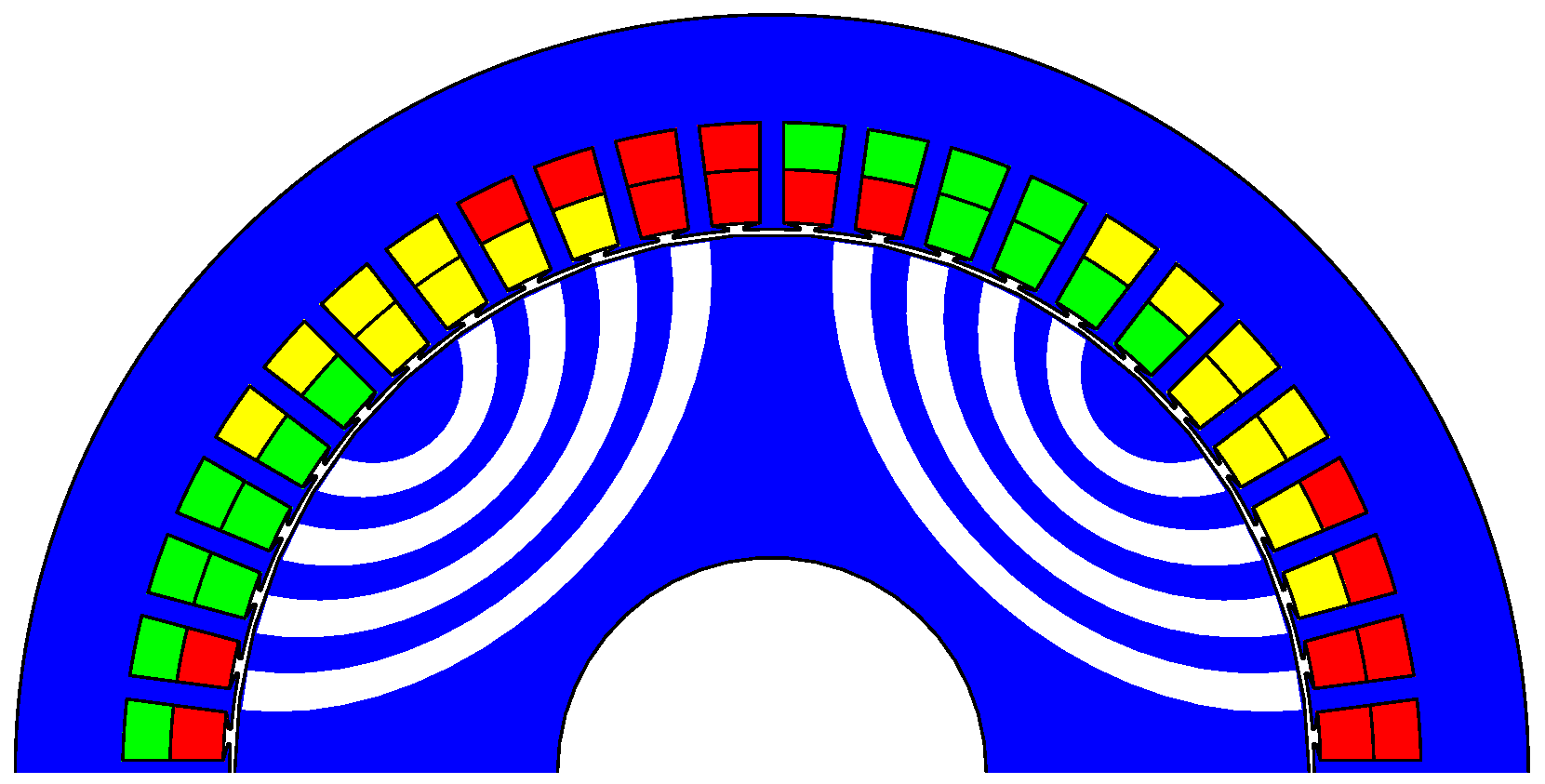
A two-pole pair ISDW machine has been chosen, with 48 slots and two slots short pitching. The machine has been designed and calculated applying the procedure explained in Section 2, with the design specifications and restrictions shown in Table 6. Due to the absence of permanent magnets, placing the rotor inside the stator is easier for SynRMs, so the air-gap of the designed machine has been reduced to 0.8 mm. Figure 26 shows one half of the designed machine geometry.
The performance characteristics of both machines have been calculated under the conditions in which the steady-state temperatures do not exceed the maximum allowable temperatures. The thermal requirements for the PMSM allow temperatures up to 155 °C in the windings (F class insulation) and 120 °C in the magnets (N40H grade magnet). Since the absence of permanent magnets in SynRMs allows less stringent thermal restrictions, the maximum allowable temperature for the SynRM is imposed to 180 °C (H class insulation).
Models by MotorCAD software for both machines are used for the thermal calculation, employing natural convection as cooling method. The results for both machines with the same volume are shown in the Table 7. The results show that, even for a higher temperature restriction in the winding, the performance characteristics of SynRMs are unable to reach the specifications of the PMSM with the same geometric restrictions.
The increase needed in the volume for meeting torque specifications is calculated. The stack length has been increased from 125 mm to 200 mm, which means that the total volume of the machine is 60% larger. The results are compared to the original PMSM performance characteristics in the Table 8.
It can be concluded that, for a comparison in which fair thermal restrictions are applied to both machines, the SynRM is able to provide around 35% lower torque than PMSMs with the same volume. For the same torque specifications, about 60% longer stacks are needed for SynRMs. In both cases, the power factor is slightly lower and efficiency is around 20% worse for the SynRM.
Nevertheless, it is expected that a proper design with an optimized rotor geometry could greatly improve the presented results. This should be studied in future works.
Only the main performance characteristics of the machines have been compared in this work, but SynRMs have some advantages over PMSMs that have not been quantified. These advantages are derived from the absence of permanent magnets: there is no demagnetization risk, they exhibit good fault tolerance, and, most importantly, manufacturing cost is reduced. It is expected that, for applications in which the machine size is not restrictive, a properly designed SynRM with a longer stack could substitute a PMSM, with a reduction of costs.
7. Conclusions
In this paper, the influence of the rotor pole number, the stator slot number and the winding type in SynRMs is studied, in order to obtain the optimal combination for low speed–high torque application.
This study has proven that high pole numbers are not suitable for SynRMs, and that FSCW machines should not be used as well in general terms. However, FSCW machines with qs = 0.5 and double layer winding have proven to be good candidates in terms of mean torque capability for applications in which having a small torque ripple is not an essential requirement.
A performance comparison between SynRM and PMSM has been conducted. It is found that, for the evaluated machine, the torque capability for the same geometric restrictions and limited maximum temperature is around 35% lower for the SynRM. For the same torque requirement and limited maximum temperature, the needed volume is around 60% larger for the SynRMs. Moreover, it is found that the power factor and the efficiency are lower for the SynRM in both cases.
The proposed calculation procedure has been validated by FEM simulations and experimental measurements, meaning that the results and conclusions of the study are validated as well.
The literature has proved that some performance characteristics of the machines are heavily dependent on the rotor geometry, and the machines in this work have been designed with the same pre-defined rotor geometry. In order to know the potential of these machines, the optimization of the rotor geometry is crucial. New machines with optimized rotor geometries should be considered in future works, with the aim of verifying the conclusions of this work, and studying the feasibility of using SynRMs for low-speed applications.
Author Contributions
All the authors contributed substantially to the work. Gurutz Artetxe performed most of the work and wrote the paper. Jesus Paredes and Borja Prieto contributed in the development of the designing tool and also in the experimental testing. Miguel Martinez-Iturralde and Ibon Elosegui supervised all the stages of the work and revised the manuscript.
Conflicts of Interest
The authors declare no conflict of interest.
References
- Lipo, T.A. Synchronous reluctance machines—A viable alternative for AC drives? Electr. Mach. Power Syst. 1991, 19, 659–671. [Google Scholar] [CrossRef]
- Miller, T.J.E.; Hutton, A.; Cossar, C.; Staton, D.A. Design of a synchronous reluctance motor drive. IEEE Trans. Ind. Appl. 1991, 27, 741–749. [Google Scholar] [CrossRef]
- Vagati, A.; Fratta, A.; Franceschini, G.; Rosso, P. AC motors for high-performance drives: A design-based comparison. IEEE Trans. Ind. Appl. 1996, 32, 1211–1219. [Google Scholar] [CrossRef]
- Boglietti, A.; Cavagnino, A.; Pastorelli, M.; Vagati, A. Experimental comparison of induction and synchronous reluctance motors performance. In Proceedings of the Fourtieth IAS Annual Meeting. Conference Record of the 2005 Industry Applications Conference, Kowloon, Hong Kong, China, 2–6 October 2005; Volume 1, pp. 474–479. [Google Scholar]
- Pellegrino, G.; Jahns, T.M.; Bianchi, N.; Soong, W.; Cupertino, F. The Rediscovery of Synchronous Reluctance and Ferrite Permanent Magnet Motors: Tutorial Course Notes; Springer: Berlin, Germany, 2016. [Google Scholar]
- Roshanfekr, P.; Lundmark, S.; Thiringer, T.; Alatalo, M. A synchronous reluctance generator for a wind application-compared with an interior mounted permanent magnet synchronous generator. In Proceedings of the 7th IET International Conference on Power Electronics, Machines and Drives (PEMD 2014), Manchester, UK, 8–10 April 2014; pp. 1–5. [Google Scholar]
- Schmidt, E. Comparison of different designs of synchronous reluctance machines with high-anisotropy rotors. In Proceedings of the 2012 XXth International Conference on Electrical Machines (ICEM), Marseille, France, 2–5 Sepetember 2012. [Google Scholar]
- Staton, D.A.; Miller, T.J.E.; Wood, S.E. Maximising the saliency ratio of the synchronous reluctance motor. IEE Proc. B-Electr. Power Appl. 1993, 140, 249–259. [Google Scholar] [CrossRef]
- Gamba, M.; Pellegrino, G.; Vagati, A. A new PM-assisted Synchronous Reluctance machine with a nonconventional fractional slot per pole combination. In Proceedings of the 2014 International Conference on Optimization of Electrical and Electronic Equipment (OPTIM), Bran, Romania, 22–24 May 2014; pp. 268–275. [Google Scholar]
- Park, J.M.; Kim, S.I.; Hong, J.P.; Lee, J.H. Rotor design on torque ripple reduction for a synchronous reluctance motor with concentrated winding using response surface methodology. IEEE Trans. Magn. 2006, 42, 3479–3481. [Google Scholar] [CrossRef]
- Spargo, C.M.; Mecrow, B.C.; Widmer, J.D.; Morton, C. Application of fractional-slot concentrated windings to synchronous reluctance motors. IEEE Trans. Ind. Appl. 2015, 51, 1446–1455. [Google Scholar] [CrossRef]
- Donaghy-Spargo, C.; Mecrow, B.C.; Widmer, J.D. Electromagnetic Analysis of a Synchronous Reluctance Motor with Single Tooth Windings. IEEE Trans. Magn. 2017, 53, 8206207. [Google Scholar] [CrossRef]
- Reddy, P.B.; Grace, K.; El-Refaie, A. Conceptual design of sleeve rotor synchronous reluctance motor for traction applications. IET Electr. Power Appl. 2016, 10, 368–374. [Google Scholar] [CrossRef]
- Vagati, A.; Boazzo, B.; Guglielmi, P.; Pellegrino, G. Design of ferrite-assisted synchronous reluctance machines robust toward demagnetization. IEEE Trans. Ind. Appl. 2014, 50, 1768–1779. [Google Scholar] [CrossRef]
- Boazzo, B.; Vagati, A.; Pellegrino, G.; Armando, E.; Guglielmi, P. Multipolar ferrite-assisted synchronous reluctance machines: A general design approach. IEEE Trans. Ind. Electron. 2015, 62, 832–845. [Google Scholar] [CrossRef]
- Pyrhonen, J.; Jokinen, T.; Hrabovcova, V. Design of Rotating Electrical Machines; John Wiley & Sons: Hoboken, NJ, USA, 2009. [Google Scholar]
- Bomela, X.B.; Kamper, M.J. Effect of stator chording and rotor skewing on performance of reluctance synchronous machine. IEEE Trans. Ind. Appl. 2002, 38, 91–100. [Google Scholar] [CrossRef]
- Pellegrino, G.; Cupertino, F.; Gerada, C. Barriers shapes and minimum set of rotor parameters in the automated design of Synchronous Reluctance machines. In Proceedings of the 2013 IEEE International Electric Machines & Drives Conference (IEMDC), Chicago, IL, USA, 12–15 May 2013; pp. 1204–1210. [Google Scholar]
- Moghaddam, R.R. Synchronous Reluctance Machine (SynRM) Design. Mater’s Thesis, Royal Institute of Technology, Stockholm, Sweden, 2007. [Google Scholar]
- Mahadevan, B.; Nagarajan, G. Design optimization of ferrite assisted synchronous reluctance motor using multi-objective differential evolution algorithm. COMPEL Int. J. Comput. Math. Electr. Electron. Eng. 2017, 36, 219–239. [Google Scholar]
- Cupertino, F.; Pellegrino, G.; Gerada, C. Design of synchronous reluctance motors with multiobjective optimization algorithms. IEEE Trans. Ind. Appl. 2014, 50, 3617–3627. [Google Scholar] [CrossRef]
- Gamba, M.; Pellegrino, G.; Cupertino, F. Optimal number of rotor parameters for the automatic design of synchronous reluctance machines. In Proceedings of the 2014 International Conference on Electrical Machines (ICEM), Berlin, Germany, 2–5 September 2014; pp. 1334–1340. [Google Scholar]
- Wang, Y.; Ionel, D.M.; Jiang, M.; Stretz, S.J. Establishing the relative merits of synchronous reluctance and PM-assisted technology through systematic design optimization. IEEE Trans. Ind. Appl. 2016, 52, 2971–2978. [Google Scholar] [CrossRef]
- Wang, Y.; Ionel, D.; Dorrell, D.G.; Stretz, S. Establishing the power factor limitations for synchronous reluctance machines. IEEE Trans. Magn. 2015, 51, 1–4. [Google Scholar]
- Matsuo, T.; Lipo, T.A. Rotor design optimization of synchronous reluctance machine. IEEE Trans. Energy Convers. 1994, 9, 359–365. [Google Scholar] [CrossRef]
- Wang, K.; Zhu, Z.Q.; Ombach, G.; Koch, M.; Zhang, S.; Xu, J. Optimal slot/pole and flux-barrier layer number combinations for synchronous reluctance machines. In Proceedings of the 2013 8th International Conference and Exhibition on Ecological Vehicles and Renewable Energies (EVER), Monte Carlo, Monaco, 27–30 March 2013; pp. 1–8. [Google Scholar]
Figure 1.
Different examples of four pole machine winding configurations (a) integral-slot distributed-winding (ISDW) (p = 2, Qs = 12, nl,w,s = 1); (b) ISDW (p = 2, Qs = 24, nl,w,s = 1); (c) ISDW (p = 2, Qs = 24, nl,w,s = 2, τa = 1); (d) fractional-slot distributed-winding FSDW (p = 2, Qs = 18, nl,w,s = 2); (e) fractional-slot concentrated-winding FSCW (p = 2, Qs = 6, nl,w,s = 1); (f) FSCW (p = 2, Qs = 6, nl,w,s = 2).

Figure 2.
Elliptic-shaped barrier rotor geometry.

Figure 3.
Synchronous reluctance machine (SynRM) vector diagram [19].
Figure 3.
Synchronous reluctance machine (SynRM) vector diagram [19].

Figure 4.
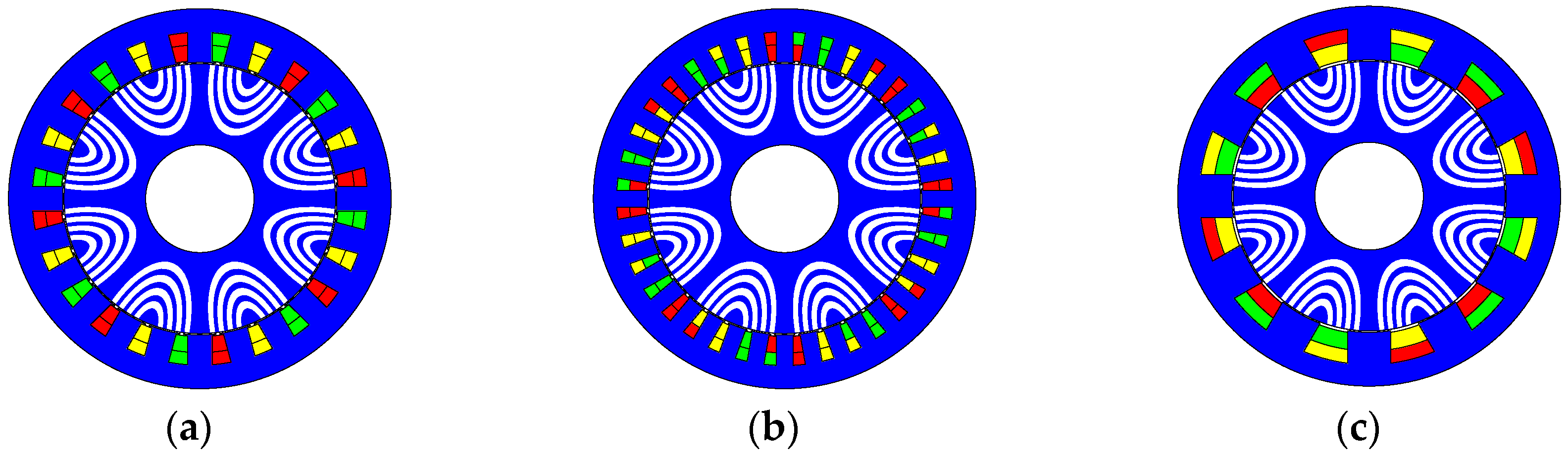
Sample machine geometries (a) ISDW (p = 4, Qs = 24); (b) FSDW (p = 4, Qs = 36); (c) FSCW (p = 4, Qs = 12, nl,w,s = 2).
Figure 4.
Sample machine geometries (a) ISDW (p = 4, Qs = 24); (b) FSDW (p = 4, Qs = 36); (c) FSCW (p = 4, Qs = 12, nl,w,s = 2).

Figure 5.
(a) Prototype rotor lamination; (b) Prototype rotor.

Figure 6.
Experimental setup for a prototype SynRM.

Figure 7.
Mean electromagnetic torque (Mem) versus pole pair number (p) and winding type.

Figure 8.
Mean electromagnetic torque (Mem) versus number of stator slots per pole and phase (qs) (a) and slot layer number (nl,w,s) for FSCW machines; (b) and pole pair number (p) for ISDW and FSDW machines.
Figure 8.
Mean electromagnetic torque (Mem) versus number of stator slots per pole and phase (qs) (a) and slot layer number (nl,w,s) for FSCW machines; (b) and pole pair number (p) for ISDW and FSDW machines.

Figure 9.
Mean electromagnetic torque (Mem) versus the difference between direct and quadrature inductances (Ld − Lq).
Figure 9.
Mean electromagnetic torque (Mem) versus the difference between direct and quadrature inductances (Ld − Lq).

Figure 10.
Mean electromagnetic torque (Mem) versus the first harmonic of the air-gap flux density (Bagap1) for (a) ISDW and FSDW machines; (b) FSCW machines.
Figure 10.
Mean electromagnetic torque (Mem) versus the first harmonic of the air-gap flux density (Bagap1) for (a) ISDW and FSDW machines; (b) FSCW machines.

Figure 11.
Mean electromagnetic torque (Mem) versus the magnetomotive force (N·I) for (a) ISDW and FSDW machines; (b) FSCW machines.
Figure 11.
Mean electromagnetic torque (Mem) versus the magnetomotive force (N·I) for (a) ISDW and FSDW machines; (b) FSCW machines.

Figure 12.
Mean electromagnetic torque (Mem) versus the magnetomotive force multiplied by the first harmonic winding factor (N·I·kω,s1) for (a) ISDW and FSDW machines; (b) FSCW machines.
Figure 12.
Mean electromagnetic torque (Mem) versus the magnetomotive force multiplied by the first harmonic winding factor (N·I·kω,s1) for (a) ISDW and FSDW machines; (b) FSCW machines.

Figure 13.
(a) Torque constant (kT); (b) Torque constant divided by the first harmonic winding factor (kτ/kω,s1) versus the number of stator slots per pole and phase (qs) and pole pair number (p) for ISDW and FSDW machines.
Figure 13.
(a) Torque constant (kT); (b) Torque constant divided by the first harmonic winding factor (kτ/kω,s1) versus the number of stator slots per pole and phase (qs) and pole pair number (p) for ISDW and FSDW machines.

Figure 14.
Torque ripple (Mem,ripple) versus (a) pole pair number (p) and winding type; (b) stator slot number per pole and phase (qs).
Figure 14.
Torque ripple (Mem,ripple) versus (a) pole pair number (p) and winding type; (b) stator slot number per pole and phase (qs).

Figure 15.
Torque ripple (Mem,ripple) versus stator slot number per pole and phase (qs) (a) and short pitching (τa) for ISDW machines; (b) and slot layer number (nl,w,s) for FSCW machines.
Figure 15.
Torque ripple (Mem,ripple) versus stator slot number per pole and phase (qs) (a) and short pitching (τa) for ISDW machines; (b) and slot layer number (nl,w,s) for FSCW machines.

Figure 16.
Air-gap flux density (Bagap) (a) waveform; (b) harmonic spectrum; for the p = 4, Qs = 24 machine.
Figure 16.
Air-gap flux density (Bagap) (a) waveform; (b) harmonic spectrum; for the p = 4, Qs = 24 machine.

Figure 17.
Air-gap flux density (Bagap) (a) waveform; (b) harmonic spectrum; for the p = 4, Qs = 36 machine.
Figure 17.
Air-gap flux density (Bagap) (a) waveform; (b) harmonic spectrum; for the p = 4, Qs = 36 machine.

Figure 18.
Air-gap flux density (Bagap) (a) waveform; (b) harmonic spectrum; for the p = 4, Qs = 12 and nl,w,s = 2 machine.
Figure 18.
Air-gap flux density (Bagap) (a) waveform; (b) harmonic spectrum; for the p = 4, Qs = 12 and nl,w,s = 2 machine.

Figure 19.
Power factor (PF) versus pole pair number (p) and winding type.

Figure 20.
Power factor (PF) versus stator slot number per pole and phase (qs) for FSCW machines.

Figure 21.
Power factor (PF) versus saliency ratio (ξ).

Figure 22.
Saliency ratio (ξ) versus (a) pole pair number (p) and winding type; (b) stator slot number per pole and phase (qs) and pole pair number (p).
Figure 22.
Saliency ratio (ξ) versus (a) pole pair number (p) and winding type; (b) stator slot number per pole and phase (qs) and pole pair number (p).

Figure 23.
Electromagnetic efficiency (ηe) versus (a) pole pair number (p) and winding type; (b) stator slot number per pole and phase (qs) and pole pair number (p).
Figure 23.
Electromagnetic efficiency (ηe) versus (a) pole pair number (p) and winding type; (b) stator slot number per pole and phase (qs) and pole pair number (p).

Figure 24.
(a) Copper losses (PCu); (b) and iron losses (PFe) versus pole pair number (p) and winding type.
Figure 24.
(a) Copper losses (PCu); (b) and iron losses (PFe) versus pole pair number (p) and winding type.

Figure 25.
(a) Copper losses (PCu) versus magnetomotive force (N·I) and pole pair number (p); (b) and electromagnetic efficiency (ηe) versus magnetomotive force multiplied by the first harmonic winding factor (N·I·kω,s1) and pole pair number (p); for ISDW and FSDW machines.
Figure 25.
(a) Copper losses (PCu) versus magnetomotive force (N·I) and pole pair number (p); (b) and electromagnetic efficiency (ηe) versus magnetomotive force multiplied by the first harmonic winding factor (N·I·kω,s1) and pole pair number (p); for ISDW and FSDW machines.

Figure 26.
p = 2, Qs = 48, τa = 2 SynRM geometry.


Table 1.
Pre-defined rotor geometric parameters.
| Parameter | Value |
|---|---|
| αd | 0.2 |
| αq | 0.2 |
| βint | 0.2 |
| βext | 0.2 |
| γα | 0.5 |
| γβ | 0.5 |
| Number of barriers | 4 |
Table 2.
Sample machine characteristics.
| Parameter Type | Parameter | Machine 1 | Machine 2 | Machine 3 |
|---|---|---|---|---|
| Machine topology | Winding type | ISDW | FSDW | FSCW |
| Pole number | 4 | 4 | 4 | |
| Slot number | 24 | 36 | 12 | |
| Geometry | Slot depth | 23.8 mm | 24.2 mm | 25.4 mm |
| Tooth width, parallel tooth | 19.4 mm | 13.4 mm | 33.9 mm | |
| Slot opening | 3 mm | 3 mm | 22.5 mm | |
| Copper slot fill factor | 0.45 | 0.45 | 0.59 | |
| Rotor barrier number | 4 | 4 | 4 | |
| Barrier geometry | αd = αq = βint = βext = 0.2; γα = γβ = 0.5 | |||
| Rotor barrier bridges | 0.8 mm | 0.8 mm | 0.8 mm | |
| Machine performance | Stator teeth flux density | 1.52 T | 1.55 T | 1.6 T |
| Stator yoke flux density | 1.56 T | 1.45 T | 1.64 T | |
| Maximum rotor barrier flux density | 2.31 T | 2.12 T | 2.19 T | |
| Current density | 8 A/mm2 | 8 A/mm2 | 8 A/mm2 | |
| Ld | 53.6 mH | 44.9 mH | 98.5 mH | |
| Lq | 16.8 mH | 13.2 mH | 39.7 mH | |
| Saliency ratio (ξ) | 3.19 | 3.39 | 2.48 | |
Table 3.
Design specifications.
| Parameter | Value |
|---|---|
| Rated torque (Nm) | 200 |
| Maximum voltage (V) | 400 |
| Maximum current (A) | 20 |
| Rated speed (rpm) | 160 |
Table 4.
Prototype SynRM characteristics.
| Parameter | Value |
|---|---|
| Electrical characteristic | |
| Rated torque (Nm) | 200 |
| Rated voltage (V) | 335 |
| Rated current (A) | 14.6 |
| Rated speed (rpm) | 160 |
| Geometric characteristics | |
| Number of pole pairs | 7 |
| Number of stator slots | 42 |
| Stack length (mm) | 150 |
| Stator outer diameter (mm) | 300 |
| Stator inner diameter (mm) | 215 |
| Air gap length (mm) | 0.8 |
Table 5.
Prototype results comparison.
| Parameter | Matlab-FEMM | Experimental Test | Difference (%) |
|---|---|---|---|
| Electromagnetic torque (Nm) | 200 | 200 | 0.0 |
| RMS phase current (A) | 14.1 | 13.6 | 3.7 |
| RMS line voltage (V) | 347 | 344 | 0.9 |
| Apparent power (kVA) | 8.48 | 8.12 | 4.4 |
| Input power (kW) | 4.82 | 4.46 | 8.1 |
| Output power (kW) | 3.35 | 3.35 | 0.0 |
| Power factor | 0.55 | 0.55 | 0.0 |
| Efficiency | 0.70 | 0.75 | 6.7 |
Table 6.
Design specifications and restrictions.
| Parameter | Value |
|---|---|
| Electrical Specifications | |
| Rated speed (rpm) | 160 |
| Maximum voltage (V) | 400 |
| Maximum current (A) | 20 |
| Geometrical Restrictions | |
| Stack length (mm) | 125 |
| Stator outer diameter (mm) | 300 |
| Stator inner diameter (mm) | 215 |
| Air-gap (mm) | 1 |
| Rotor inner diameter (mm) | 85 |
| Winding Restrictions | |
| Fill factor, distributed winding | 0.45 |
| Copper slot fill factor, single layer concentrated winding | 0.65 |
| Copper slot fill factor, double layer concentrated winding | 0.6 |
| Current Density and Reference Flux-Densities | |
| Current density (A/mm2) | 8 |
| Stator yoke peak flux density (T) | 1.6 |
| Stator teeth peak flux density (T) | 1.6 |
| Air-gap peak flux density (T) | 0.85 |
Table 7.
SynRM and permanent magnet synchronous machines (PMSM) characteristics for the same volume.
Table 7.
SynRM and permanent magnet synchronous machines (PMSM) characteristics for the same volume.
| Parameter | SynRM | PMSM |
|---|---|---|
| Electromagnetic torque (Nm) | 103 | 162 |
| Torque ripple (Nm) | 4.9 | 0.6 |
| Line voltage (V) | 319 | 330 |
| Phase current (A) | 5.7 | 6.5 |
| Apparent power (kVA) | 3.15 | 3.71 |
| Input power (kW) | 2.73 | 3.35 |
| Output power (kW) | 1.73 | 2.71 |
| Power factor | 0.85 | 0.90 |
| Efficiency | 0.63 | 0.81 |
Table 8.
SynRM and PMSM characteristics for the same torque requirement.
| Parameter | SynRM | PMSM |
|---|---|---|
| Electromagnetic torque (Nm) | 162 | 162 |
| Torque ripple (Nm) | 7.5 | 0.6 |
| Line voltage (V) | 332 | 330 |
| Phase current (A) | 8.05 | 6.5 |
| Apparent power (kVA) | 4.63 | 3.71 |
| Input power (kW) | 3.92 | 3.35 |
| Output power (kW) | 2.71 | 2.71 |
| Power factor | 0.82 | 0.90 |
| Efficiency | 0.69 | 0.81 |
© 2018 by the authors. Licensee MDPI, Basel, Switzerland. This article is an open access article distributed under the terms and conditions of the Creative Commons Attribution (CC BY) license (http://creativecommons.org/licenses/by/4.0/).
Share and Cite
MDPI and ACS Style
Artetxe, G.; Paredes, J.; Prieto, B.; Martinez-Iturralde, M.; Elosegui, I. Optimal Pole Number and Winding Designs for Low Speed–High Torque Synchronous Reluctance Machines. Energies 2018, 11, 128. https://doi.org/10.3390/en11010128
AMA Style
Artetxe G, Paredes J, Prieto B, Martinez-Iturralde M, Elosegui I. Optimal Pole Number and Winding Designs for Low Speed–High Torque Synchronous Reluctance Machines. Energies. 2018; 11(1):128. https://doi.org/10.3390/en11010128
Chicago/Turabian StyleArtetxe, Gurutz, Jesus Paredes, Borja Prieto, Miguel Martinez-Iturralde, and Ibon Elosegui. 2018. "Optimal Pole Number and Winding Designs for Low Speed–High Torque Synchronous Reluctance Machines" Energies 11, no. 1: 128. https://doi.org/10.3390/en11010128
Note that from the first issue of 2016, this journal uses article numbers instead of page numbers. See further details here.