Article

Magnetic Field and Torque Output of Packaged Hydraulic Torque Motor

1
School of Automation Science and Electrical Engineering, Beihang University, Beijing 100083, China
2
Research Institute of Beihang University in Shenzhen, Shenzhen 518057, China
3
AVIC Xian Flight Automatic Control Research Institute, Xi’an 710065, China
4
Department of Electrical and Electronic Engineering, University of Nottingham, Nottingham NG7 2RD, UK
*
Author to whom correspondence should be addressed.
Energies 2018, 11(1), 134; https://doi.org/10.3390/en11010134
Submission received: 17 November 2017 / Revised: 23 December 2017 / Accepted: 25 December 2017 / Published: 5 January 2018

Abstract

:
Hydraulic torque motors are one key component in electro-hydraulic servo valves that convert the electrical signal into mechanical motions. The systematic characteristics analysis of the hydraulic torque motor has not been found in the previous research, including the distribution of the electromagnetic field and torque output, and particularly the relationship between them. In addition, conventional studies of hydraulic torque motors generally assume an evenly distributed magnetic flux field and ignore the influence of special mechanical geometry in the air gaps, which may compromise the accuracy of analyzing the result and the high-precision motion control performance. Therefore, the objective of this study is to conduct a detailed analysis of the distribution of the magnetic field and torque output; the influence of limiting holes in the air gaps is considered to improve the accuracy of both numerical computation and analytical modeling. The structure and working principle of the torque motor are presented first. The magnetic field distribution in the air gaps and the magnetic saturation in the iron blocks are analyzed by using a numerical approach. Subsequently, the torque generation with respect to the current input and assembly errors is analyzed in detail. This shows that the influence of limiting holes on the magnetic field is consistent with that on torque generation. Following this, a novel modified equivalent magnetic circuit is proposed to formulate the torque output of the hydraulic torque motor analytically. The comparison among the modified equivalent magnetic circuit, the conventional modeling approach and the numerical computation is conducted, and it is found that the proposed method helps to improve the modeling accuracy by taking into account the effect of special geometry inside the air gaps.

1. Introduction

Hydraulic torque motors are one important component in electro-hydraulic servo valves that convert electrical power into mechanical motions. These directly affect the output performance of servo valves [1,2,3,4,5]. Some research has been conducted on the dynamics and control of hydraulic torque motors. For example, Li et al. [6,7,8] analyzed the vibrational characteristics of armature assembly in the hydraulic torque motor and presented the generation of self-excited noise in servo valves. Magnetic fluid was added into the air gaps of the torque motor to increase the damping effect and thus improve the dynamic response characteristics of the system. The simulation result shows that the magnetic fluid helps to overcome self-excited high-frequency oscillations and noise, and the stability and anti-interference capability of the torque motor are enhanced greatly. Somashekhar et al. [9] developed a mathematical model of a jet pipe electro-hydraulic flow control servo valve with built-in mechanical feedback. The dynamic characteristics of the armature assembly of the torque motor were studied. The simulation presents the dynamics of the jet pipe, spool, and actuator displacement in achieving the equilibrium position when the applied torque and restoring torques balance, which is known as the steady state [10]. Chu et al. [11] proposed a modeling and simulating method for the analysis of the system’s dynamic behavior on the basis of generalized stochastic petri nets (GSPN) theory and the collected basic failure modes and failure rate data of the jet pipe servo valve. The result verifies that research methods based on GSPN are concise and realistic. Urata et al. [12] analyzed the influence of an unequal thickness of air gaps on the torque output in servo valve torque motors and presented how an imbalance of air gaps changes the flux density and the resultant torque characteristics. Liu et al. [1] analyzed the influence of the reluctance of magnetic elements on the torque motor. Considering the magnetic reluctance, a mathematical model of a servo valve torque motor was developed on the basis of the fundamental laws of electromagnetism. By using this mathematical model, the electromagnetic torque constant and magnetic spring stiffness were evaluated for a given set of torque motor parameters. Shi et al. [13] carried out a numerical fault simulation on the torque motor. The result shows that the decrease in the spring stiffness in the motor increases the angular displacement and compromises the system stability. The phase difference of the coil current is useful for fault diagnosis. In summary, it can be found that research on the characteristics analysis of the hydraulic torque motor is seldom found in literature, including the distribution of the electromagnetic field and torque output, and particularly the relationship between them. In addition, the magnetic field and torque analysis has been conducted by ignoring the influence of special geometries such as limiting holes inside the air gaps and simply assuming that the magnetic flux is evenly distributed there. This assumption apparently facilitates the theoretical studies, yet unavoidably compromises the model’s precision in terms of the magnetic field and torque output and thus the high-performance real-time motion control of the armature. Li [14] described the principle of the magnetic property of the test, developed a test system for magnetic characteristics, and established the relationship between the electromagnetic torque and current control current.
Therefore, the objective of this paper is to systematically analyze the three-dimensional distribution of the magnetic field and torque output performance of the packaged hydraulic torque motor and the major factors that influence the magnetic field and torque generation. The effect of a non-regular geometry of air gaps on the magnetic field and torque output has been analyzed by numerical computation. A novel modified equivalent magnetic circuit is proposed to improve the precision of the analytical model of torque output. The rest of the paper is organized as follows. Section 2 briefly introduces the schematic structure and operating principle of the torque motor. Section 3 analyzes the magnetic field distribution in the air gaps and the magnetic saturation in iron blocks. Section 4 presents the influence of the current input and assembly errors on the torque output through numerical computation. Section 5 formulates the torque output analytically, by considering the special geometry inside the air gaps. This shows that compared with conventional modeling approaches [15,16,17], the proposed modified magnetic circuit helps to improve the precision of the torque output, which in turn may benefit the motion control of the torque motor.

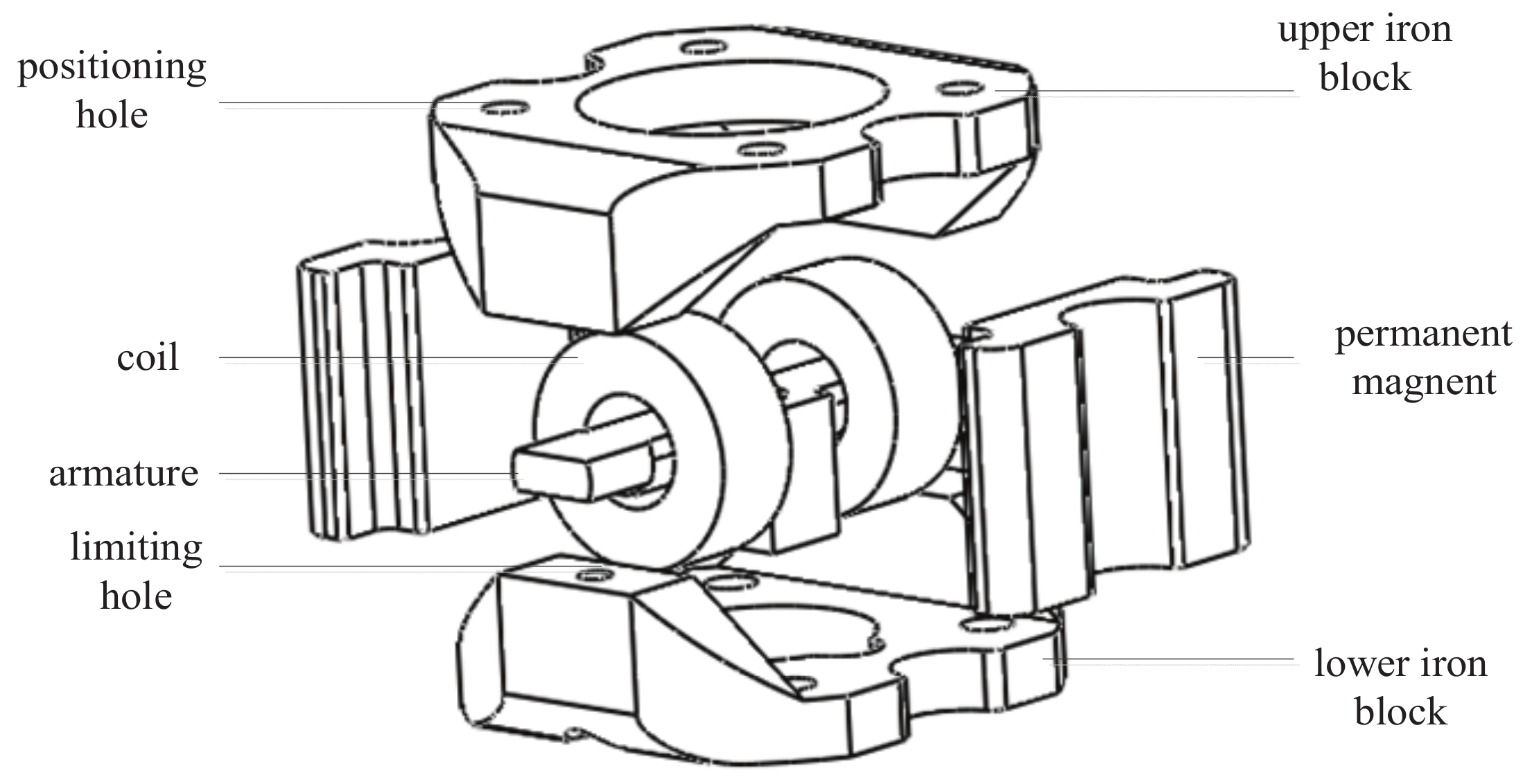
2. Schematic Structure and Operating Principle

The torque motor is used as the nozzle flapper servo valve; it is the pilot-stage electro-hydraulic servo valve. The servo valve has been widely used in electro-hydraulic servo control systems in the fields of aviation and spaceflight. The input electrical signals are translated into mechanical signals, and the pilot stage electro-hydraulic servo valve can be controlled by the rotation of the armature. The schematic structure of the packaged hydraulic torque motor is presented in Figure 1. It consists of five major parts, that is, the upper iron block, lower iron block, permanent magnet, excitation coil and armature. The upper and lower iron blocks and armature are made from a ferromagnetic material with a high permeability or low magnetic reluctance, which helps to reduce the magnetic energy loss in the torque motor.
The operating principle is illustrated in Figure 2. Specifically, Figure 2a presents the hydraulic torque motor without a power supply. The permanent magnets generate magnetic flux running through the upper iron block, the armature, the lower iron block and the magnet, consequently in a closed form. As a result of the symmetry of the motor structure, the magnetic flux distribution in the four air gaps is the same. Therefore, the magnetic attraction force at the four air gaps are equal to each other. The armature is thus kept in the balanced position.
In Figure 2b, however, the two coils are energized with the same current input. The power supply goes out of the paper for the upside of the windings and returns into the paper for the downside, forming a closed current loop. Both coils produce a magnetic flux going through two parallel ways, that is, one from the armature to the upper iron, returning to the armature, and the other from the armature to the lower iron block, returning to the armature. The magnetic flux produced by the coils is superposed with that by the permanent magnets. The resulting magnetic flux at air gaps 1 and 4 is enhanced as a result of the same direction of the flux by the magnet and coil, whereas it is weakened at air gaps 2 and 3 as a result of the opposite direction of the flux by the magnet and coil. Therefore, the attraction force at air gaps 1 and 4 is larger than that of 2 and 3, which causes the armature to rotate clockwise. Similarly, if the current input in the two coils reverses the direction, as shown in Figure 2c, the superposition of the magnetic flux leads to the anticlockwise rotation of the armature. The continuous current switch leads to reciprocating motions of the armature. The opening and closing of the servo valve is dependent on the armature motion and thus the direction of excitation current, and the opening angle of the servo valve can be controlled by the value of the excitation current.

3. Analysis of Magnetic Field Distribution

In this section, we focus on the study of the magnetic field distribution because it affects the output performance of the packaged hydraulic torque motor significantly.

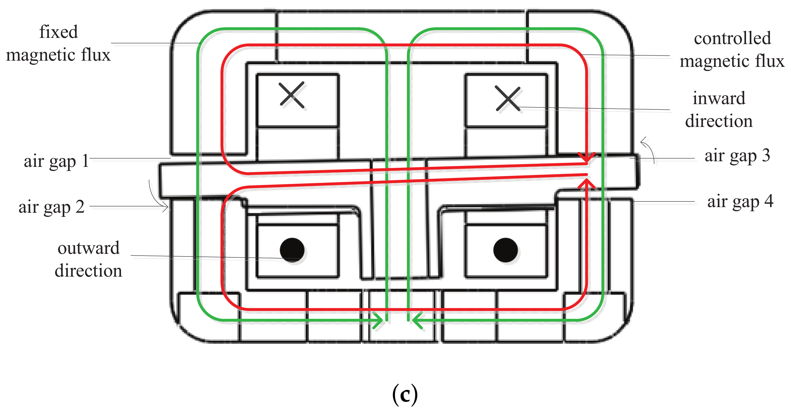
3.1. Magnetic Field Distribution in Air Gaps

The analysis of the magnetic field distribution in air gaps of hydraulic torque motors has been done by other researchers previously. However, for simplification, these analyses generally assume an evenly distributed field in the air gaps, and the influence of the limiting hole in the air gap is ignored. In this study, to analyze the magnetic field distribution comprehensively, the influence of limiting holes is included. One coordinate system is established as shown in Figure 3. The x y -plane of the coordinate system is in the middle position of the air gap. The numerical result of the magnetic field distribution with respect to the x and y coordinates in the four air gaps is presented in Figure 4. Figure 4a,c,e,g represents the flux field status of the motor without a power supply, and the rest of the figures represent the flux field status with a 10 mA current input.
Theoretically, because of the symmetry of the magnetic circuit in the motor, the magnetic flux of air gap 1 is the same as that of air gap 4, and the magnetic flux of air gap 2 is the same as that of air gap 3. As indicated in Figure 4a,b,e,f, the magnetic flux density is relatively evenly distributed in air gaps 1 and 3, particularly at the center of the air gap. In contrast, the magnetic flux density in air gaps 2 and 4 is not constant. One caved surface is presented at the center of the air gaps 2 and 4 as shown in Figure 4c,d,g,h. This is mainly caused by the limiting holes. In addition, the power supply in coils changes the magnetic flux density in the air gaps. For example, the flux density in air gap 1 is about 600 and 500 mT for a 0 and 10 mA power supply, respectively, as a result of the energizing of coils and the subsequent cancelation effect of the flux field by the magnet and coils. Similarly, the magnetic flux density of air gap 3 is about 610 and 714 mT for a 0 and 10 mA power supply, respectively. The magnetic flux density of air gap 2 is about 600 mT at the edge of the caved surface and 470 mT at the bottom when there is no power supply; it is improved to 680 and 510 mT, respectively, when 10 mA is supplied into the coils. Similarly, the maximum and minimum value of the magnetic flux density in air gap 4 without a current input is about 500 and 270 mT at the edge and bottom of the caved surface, respectively; this is decreased to 370 and 200 mT when there is power supply. Therefore, the attraction force at air gaps 2 and 3 is larger than that at air gaps 1 and 4, which causes the rotational motion to be in an anticlockwise direction. The limiting holes at air gaps 2 and 4 may cause problems as follows.
  • They may cause an unequal magnetic flux density at air gaps 1, 3, 2 and 4, and thus the force components at these air gaps have opposite directions but different values. The total force is not vanished, which leads to additional payload and thus friction torque on the bearings.
  • They may complicate the formulation of the magnetic field and torque output and thus compromise the high-performance real-time motion control of the armature.
Therefore, to improve the control performance and reliability of the hydraulic torque motor, the size of the limiting holes should be reduced as much as possible.

3.2. Magnetic Saturation in Iron Blocks

Magnetic saturation is a common characteristic of magnetic materials [18,19]. In most cases, we hope that the magnetic flux density can increase with respect to the magnetic field strength. However, in practice, the magnetic flux density does not continue to increase proportionally after reaching a certain value. This indicates that the magnetic flux is saturated at this point. In general, a magnetic material is characterized by a B H curve, as illustrated in Figure 5. The B H curve can be divided into three parts, that is, linear, nonlinear and saturation regions. In general, the magnetic material works in the linear region. When the flux density reaches about 0.7 T, the iron block begins to enter the nonlinear region. Once the magnetic flux density reaches about 1.2 T, the iron block is saturated seriously. In this situation, the system’s working efficiency may be decreased significantly. Therefore, it is important to analyze the magnetic saturation in the iron blocks of the torque motor.
The increase in the excitation current in the coils changes the magnetic flux density in the air gaps. The relationship between the excitation current and the magnetic flux density of air gaps 1 and 3 has been analyzed numerically and is presented in Figure 6. This indicates that the magnetic flux density does not change greatly after the current input reaches about 40 mA, that is, when the iron block goes into the saturation status. We can also find that the iron block enters the non-linear working region when the current input reaches about 20 mA. The result can help us to determine the reasonable range of power supply for the motion control of the torque motor, that is, 20 mA for this motor design.
To observe the magnetic saturation of the motor comprehensively, the distribution of the magnetic field inside the system is also analyzed. The result of the numerical computation is shown in Figure 7. It is found that there is magnetic saturation near the four positioning holes at the four corners of the upper and lower iron blocks. The positioning holes reduce the sectional area of the magnetic flux loop and thus increase the flux density significantly nearby. In addition, the saturation can also be found near the limiting holes of the lower iron block and the center assembly hole of the upper iron block for a similar reason. Therefore, the hole size could be reduced to decrease the magnetic saturation in these regions, and materials at the non-saturated region may be removed to reduce the overall weight of the system.

4. Analysis of Torque Generation

4.1. Relationship between Current Input and Torque Output

The relationship between the current input and torque output with respect to different sizes of limiting holes has been analyzed, and the result is presented in Figure 8. In general, the torque output is directly proportional to the current input. However, when the excitation current is larger than a certain value, the torque output no longer increases directly proportionally. This is mainly caused by the magnetic saturation in the motor. For example, the directly proportional relationship only applies to the third curve in Figure 8 (D = 4 mm) when the current input is less than about 18 mA. This result is consistent with the magnetic field analysis in the last section.
The influence of limiting holes on the torque generation has also been analyzed. Figure 8 shows that the torque output decreases with respect to the hole sizes. From the previous section, we know that a large size of limiting holes increases the magnetic saturation in the flux loop. The magnetic saturation in turn constrains the improvement of the torque output. The larger the hole diameter, the less the improvement of the torque output. Furthermore, the large diameter of the limiting holes leads to the saturation point at a low current input. Therefore, similarly to the magnetic field analysis, a smaller size of limiting holes is preferred to increase the torque output. In general, the torque motor is supposed to work in the linear region to ensure good motion control performance.

4.2. Influence of Assembly Errors on Torque Output

The influence of assembly errors on the torque output is important, particularly for high-precision motion control of the motor armature and valve spool. Such a study has never been reported in literature before. The assembly error of the armature directly influences the magnetic flux distribution in the air gaps and thus may change the torque generation. Therefore, in this section, we focus on the influence of the armature assembly error.

4.2.1. Rotational Assembly Error

One typical assembly error is the rotational error; that is, the armature has an initial rotational angle about the Y or Z axis of the coordinate system, as indicated in Figure 9, and it is about 0– 0.3 according to experience. The influence of the rotational assembly error on the torque generation is shown in Figure 10. To observe the effect comprehensively, a different current is supplied into the coils. It is found that the influence of the rotational assembly error on the torque generation is ignorable, regardless the current input in the coils.

4.2.2. Displacement Assembly Error

Besides the rotational assembly errors, the armature may move along the axis of the coordinate system a very short distance, causing the displacement assembly error. We assume that the armature moves a small distance along the Z axis, which changes the thickness of the air gaps. The influence of the displacement assembly error on the torque generation has been analyzed, and the result is shown in Figure 11. It is found that within a certain displacement, such as 0–0.03 mm, the influence of the assembly error on the torque output is not significant.

5. Mathematical Formulation of Torque Output

The mathematical formulation of the torque output relates the current input to the torque output in an analytical way, and it helps to achieve high-performance motion control of the system [20,21,22]. In this section, the torque formulation of the hydraulic torque motor is conducted by considering the influence of limiting holes, which has not been done before.

5.1. Assumptions

  • The thicknesses of the four air gaps are equal at the balanced position or when there is no excitation current applied to the coils.
  • The ferromagnetic material or iron block works at the linear region of the B H curve.
  • The magnetic hysteresis of the ferromagnetic material is small and negligible.
As shown in Figure 12, there are two independent closed circuits in the torque motor’s magnetic circuit.

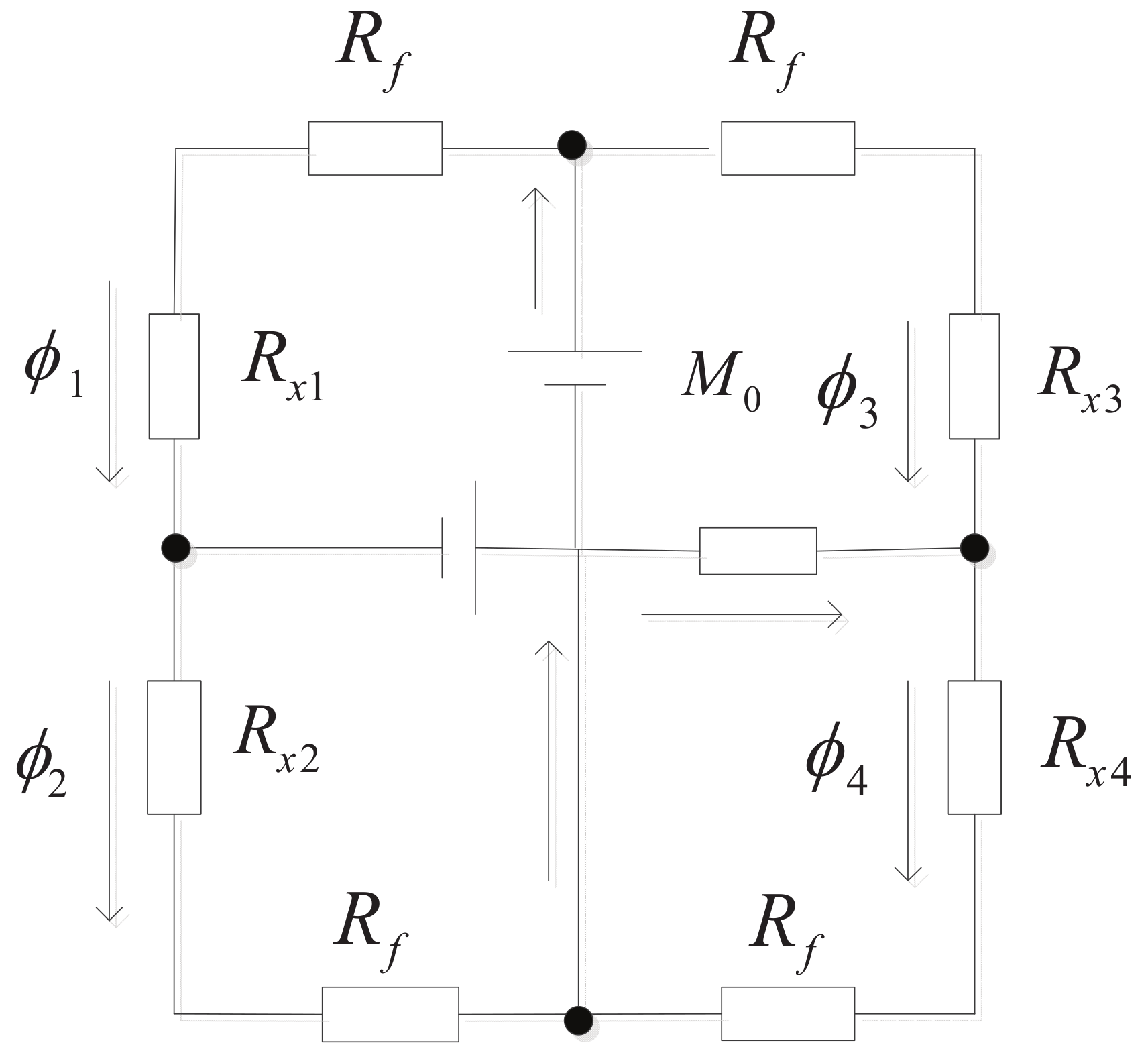
5.2. Magnetic Reluctance in the Flux Loop

R x , 1 , R x , 2 , R x , 3 and R x , 4 are the magnetic reluctance of the four air gaps that can be obtained from
R x 1 = R x 4 = g x μ 0 A g
R x 2 = R x 3 = g + x μ 0 A g
where μ 0 (Wb/A) is the relative permeability of free space, A g (mm 2 ) is the section area of the air gap, g (mm) is the thickness of air gap, and x (mm) is the linear displacement of the armature end. According to the defined magnetic reluctance, the magnetic reluctance of the iron blocks and armature can be expressed as
R f = l f μ r μ 0 A f , R d = l d μ r μ 0 A d
where l f and A f are the length of the magnetic circuit and the cross-sectional area of the iron block perpendicular to the flux loop, respectively; l d and A d are the length of the magnetic circuit and the cross-sectional area of the armature, respectively. In a true torque motor, the shape of the iron block is irregular, and the cross-sectional area is different. Therefore, in this study, the iron block is divided into two parts. The first part is a quarter of the annular cylinder, and the second part is a cuboid. The cross-sectional area of these are A f 1 and A f 2 , respectively. In the equivalent magnetic circuit, these two parts can be considered as two components connected in series. Thus the magnetic reluctance should have the following new form:
R f = l f 1 μ r μ 0 A f 1 + l f 2 μ r μ 0 A f 2
When the armature is at the initial position, the reluctance of the air gaps can be written as
R g = g μ 0 A g
Because the rotational angle θ of the armature is very small, the displacement of the armature ends can be written as x = l θ , and the thicknesses of the air gaps are expressed as g + x and g x .

5.2.1. Magnetic Circuit Equations

As shown in Figure 12, there are two independent closed magnetic circuits in the torque motor. For each of these, similarly to the electric circuit, Kirchhoff’s law can be used to solve the magnetic flux in the magnetic circuit as follows:
ϕ 1 = ϕ 4 ϕ 2 = ϕ 3 ϕ 1 ϕ 2 = ϕ 5 M 0 + N Δ i = ( R f + R x 1 ) ϕ 1 + ( R f + R x 4 ) ϕ 4 + R d ϕ 6 M 0 N Δ i = ( R f + R x 3 ) ϕ 3 + ( R f + R x 2 ) ϕ 2 R d ϕ 6
where M 0 is the magnetizing potential of the permanent magnet; N Δ i are the ampere turns of the excitation coils; ϕ 1 , ϕ 2 , ϕ 3 and ϕ 4 are the magnetic flux in the four air gaps; ϕ 5 and ϕ 6 are the magnetic fluxes of the permanent magnet and armature, respectively. The solutions of Equation (6) can be expressed as
ϕ 1 = ( [ 1 + R g x g R g + R f ] ϕ c + [ 1 + R g x g R g + R f + R f ] ϕ g ) k + 1 k + 1 x g 2
ϕ 2 = ( [ R g x g R g + R f 1 ] ϕ c + [ 1 R g x g R g + R d + R f ] ϕ g ) k + 1 k + 1 x g 2
where ϕ c is the magnetic flux generated by the excitation current in the air gap, ϕ g is the magnetic flux in the air gap generated by the permanent magnet without the excitation current, and k is a parameter to simplify the results. The three parameters can be written as
ϕ c = N c Δ i 2 ( R g + R d + R f ) , ϕ g = M 0 2 ( R g + R f ) , k = R f ( R d + R f ) R g 2 + R g + 2 R f R g

5.2.2. Derivation of Magnetic Force Generation

The magnetic force generated by the Maxwell stress between the armature ends and the iron blocks can be expressed as
F = ϕ 2 2 μ 0 A g
According to Equation (10), the force created by the magnetic force in the motor is
F 1 = ϕ 1 2 2 μ 0 A g , F 2 = ϕ 2 2 2 μ 0 A g
The torque output can be written as
T = 2 l ( F 1 F 2 )
where l is the half-length of the armature. Combining Equations (7), (8) and (12) yields
T = l μ 0 A g ( ϕ 1 2 ϕ 2 2 )
For the convenience of calculation, Equation (13) is reorganized as
T = l μ 0 A g ϕ 1 + ϕ 2 ( ϕ 1 ϕ 2 )
According to Equations (7) and (8), we have
ϕ 1 + ϕ 2 = ( [ 2 R g x g R g + R f ] ϕ c + 2 ϕ g ) k + 1 k + 1 x g 2 , ϕ 1 ϕ 2 = ( 2 ϕ c + [ 2 R g x g R g + R d + R f ] ϕ g ) k + 1 k + 1 x g 2 .
Then
T = P t 1 + m n 2 ( x g ) 2 Δ i + P m 1 + m ( ϕ c ϕ g ) 2 θ × k + 1 k + 1 ( x g ) 2 2
where
P t = 2 N ϕ g ( l g ) n , P m = 4 ϕ g 2 R g ( l g ) 2 n , m = R f + R d + R g R g + R f , n = R g R f + R d + R g
Because ( x / g ) 2 < < 1 and ( ϕ c / ϕ g ) 2 < < 1 , Equation (16) can be represented in a simple way as
T = P t Δ i + P m θ
Equation (17) indicates that the torque output is proportional to the current input and the rotational angle of the armature. P t and P m can be considered as structure parameters that have nothing to do with the coil current or armature rotational angle. The major parameters are listed in Table 1; H is a part of the unit of magnetic permeability.
Substituting these parameters into Equation (17), the approximate relationship between the output torque, rotation angle and excitation current can be obtained as
T = 11.052 i + 9.106 θ
where i (A) is the coil current and θ (rad) is the rotational angle of the armature. It is noted that the mathematical model is based on the linear working region of the B H curve. The excitation current should have an amplitude range. When the magnetic field strength reaches about 0.75 T, the iron block gets into the nonlinear working region. Assuming that the armature is at the balanced position, the corresponding excitation current can be obtained from Equation (18). The current input should be in the range of 0–20 mA.

5.3. Numerical Simulation of Torque Output

A numerical simulation has been conducted to validate the accuracy of the mathematical torque model. The major parameters for the simulation are shown in Table 2.
In the numerical simulation, the current input and rotational angle changed value continuously, and thus the corresponding torque output could be obtained. The relationship between the torque output, current input and rotational angle is presented in Figure 13. Through a curve fitting approach, it has been found that when the armature is at the initial position, the torque output shows good symmetry. When the direction of the current is reversed, the torque output also reverses. The torque output is directly proportional to the rotational angle and the current input, which is consistent with the analytical model.
The relationship can be represented mathematically as
T = 10.2 i + 8.96 θ
By comparing Equations (18) and (19), the coefficients in the mathematical model are essentially consistent with those of the fitted model.

5.4. Modification of Analytical Torque Model

From the above analysis, we can still see that there is little difference between the analytical torque model and the numerical result. This is mainly caused by the ignorance of limiting holes that apparently affect the magnetic flux loop. As discussed in the previous sections, the limiting holes increase the magnetic reluctance of the iron blocks and may lead to magnetic saturation. The magnetic field distribution and torque output are thus both affected when a large current is supplied into the system. In most applications, the influence of the limiting holes is usually ignored to simplify the calculation and obtain a compact solution. However, it may compromise the high-precision motion control in some cases. Therefore, it is meaningful to take its influence into consideration in the mathematical torque model.
When the influence of the limiting holes is considered, the magnetic reluctance of the four air gaps is no longer equal, even at the initial armature position. In other words, the magnetic fluxes of the four air gaps do not have the previous relationship, and thus ϕ 1 ϕ 4 and ϕ 2 ϕ 3 . Equation (6) is replaced by
ϕ 1 + ϕ 3 = ϕ 2 + ϕ 4 ϕ 1 ϕ 2 = ϕ 5 M 0 = ( R f + R x 1 ) ϕ 1 + ( R x 2 + R f * ) ϕ 2 M 0 + N Δ i = ( R f + R x 1 ) ϕ 1 + ( R f * + R x 4 ) ϕ 4 + R d ϕ 5 M 0 N Δ i = ( R f + R x 3 ) ϕ 3 + ( R f * + R x 2 ) ϕ 2 R d ϕ 5
where R f * is the magnetic reluctance of the iron block by considering the influence of the limiting holes. The diameter of the limiting hole is about 2 mm, and the diameter of the positioning hole is about 4 mm. The cross-sectional areas of the limiting holes and positioning holes should be subtracted from the area of the block iron along the magnetic circuit, as shown in Figure 14.
Therefore, R f * = 6.88 × 10 5 H 1 . The output torque can be obtained as
T = 10.55 i + 8.79 θ
The previously derived mathematical torque model, the modified model and the numerical result are all presented in Figure 15 for comparison. It can be found that the modified analytical model reduces the difference with the numerical result greatly, which may benefit the design optimization and control implementation of the hydraulic torque motor in future work. The influence of the limiting holes is more significant when the excitation current becomes larger. The relative difference of the modified model is less than 4% of the maximum value when the current input is less than the rated value, that is, 10 mA.

6. Conclusions

The study analyzes the magnetic field distribution and torque output of the hydraulic torque motor systematically. The flux distribution in the air gaps is presented with respect to rectangular coordinates, and the magnetic saturation in the iron blocks is analyzed numerically. Unlike conventional studies, the influence of limiting holes on the flux distribution and magnetic saturation is analyzed in detail, which helps to improve the precision of results. The relationship between the torque output and current input as well as the sizes of limiting holes is analyzed and presented in curves. The result is consistent with that of magnetic field analysis and helps to choose a rated current for the torque motor. Furthermore, the influence of assembly errors on the torque output is also studied. A novel modified torque model by including the influence of limiting holes is proposed and is validated with numerical computation. This shows that the modified torque model can help to improve the modeling precision of the conventional equivalent magnetic circuit effectively. It can be implemented into high-precision motion control of the torque motor in the future.

Acknowledgments

The authors acknowledge the financial support from the National Natural Science Foundation of China (NSFC) under Grant No. 51575026, the National Key Basic Research Program of China (973 Program, 2014CB046406), NSFC51235002, the Fundamental Research Funds for the Central Universities, and the Science and Technology on Aircraft Control Laboratory.

Author Contributions

L.Y. and Z.D. conceived and designed the study; Q.Z. analyzed the data; S.N., Y.D. and C.G. contributed the materials and analysis tools; Besides, Z.D. wrote the paper, L.Y. reviewed and edited the manuscript. All authors read and approved the manuscript.

Conflicts of Interest

The authors declare no conflict of interest.

References

  1. Liu, C.; Jing, H. Influence of Magnetic Reluctances of Magnetic Elements on Servo Valve Torque Motors. Chin. J. Mech. Eng. 2016, 29, 136–143. [Google Scholar] [CrossRef]
  2. Liu, C. A Seventh-order Model for Dynamic Response of an Electro-hydraulic Servo Valve. Chin. J. Aeronaut. 2014, 27, 1605–1611. [Google Scholar] [CrossRef]
  3. Wang, H.; Gong, G. Steady Flow Torques in a Servo Motor Operated Rotary Directional Control Valve. Energy Convers. Manag. 2016, 112, 1–10. [Google Scholar] [CrossRef]
  4. Urata, E. On the Torque Generated in a Servo Valve Torque Motor Using Permanent Magnets. J. Mech. Eng. Sci. 2007, 221, 519–525. [Google Scholar] [CrossRef]
  5. Liu, X. The Characteristic and Control Technology Research on 3-Level Electro-Hydraulic Servo Valve; Harbin Institute of Technology: Harbin, China, 2010; pp. 1–2. [Google Scholar]
  6. Li, H.; Li, S. Study of Self-Excited Noise and Pressure Oscillations in a Hydraulic Jet-Pipe Servo-Valve with Magnetic Fluids; Harbin Institute of Technology: Harbin, China, 2010. [Google Scholar]
  7. Li, S. Influence of Magnetic Fluids on the Dynamic Characteristics of a Hydraulic Servo-valve Torque Motor. Mech. Syst. Signal Process. 2008, 22, 1008–1015. [Google Scholar] [CrossRef]
  8. Aung, N.; Li, S. A Numerical Study of Cavitation Phenomenon in a Flapper-nozzle Pilot Stage of an Electrohydraulic Servo-valve with an Innovative Flapper Shape. Energy Convers. Manag. 2014, 77, 31–39. [Google Scholar] [CrossRef]
  9. Somashekhar, S.; Singaperumal, M. Mathematical Modelling and Simulation of a Jet Pipe Electrohydraulic Flow Control Servo Valve. Syst. Control Eng. 2007, 221, 365–382. [Google Scholar] [CrossRef]
  10. Pham, X.H.S.; Yin, Y.B.; Zhang, X. Optimal Design for Torque Motor of Jet Pipe Electro-hydraulic Servo-valve Based on Dynamic Stiffness. In Proceedings of the 2012 4th International Conference on Intelligent Human-Machine Systems and Cybernetics, Nanchang, Jiangxi, China, 26–27 August 2012. [Google Scholar]
  11. Chu, Y. Research on Dynamic Reliability of a Jet Pipe Servo Valve Based on Generalized Stochastic Petri Nets. Int. J. Aerosp. Eng. 2015, 2015, 171642. [Google Scholar] [CrossRef]
  12. Urata, E. Influence of Unequal Air-gap Thickness in Servo Valve Torque Motors. J. Mech. Eng. Sci. 2007, 221, 1287–1297. [Google Scholar] [CrossRef]
  13. Wang, Z. Fault Modeling and Simulation of the Torque Motor Used in Electrohydraulic Servoo Valve. Hydraul. Pnenmatics Seals 2010, 10, 30–32. [Google Scholar]
  14. Liu, C.; Shao, D.; Wang, G. Development and Experimental Study of Magnetic Property for Servo Valve Torque Motor. Key Eng. Mater. 2014, 621, 233–238. [Google Scholar] [CrossRef]
  15. Wu, H. Non-linear Math Model of Torgue Motor Based on MATLAB. Mech. Magnet Dev. 2010, 25, 40–45. [Google Scholar]
  16. Liu, L.; Wang, H. Methods of Electromagnetic Force Calculation for Engineering Application. Missile Space Vehcile 2007, 1, 40–45. [Google Scholar]
  17. Tao, G.; Chen, H.Y.; He, Z.B. Optimal Design of the Magnetic Field of Ahigh-speed Response Solenoid Valve. J. Mater. Process. Technol. 2002, 129, 555–558. [Google Scholar] [CrossRef]
  18. Kar, N.; E1-Serafi, A. Measurement of the Saturation Characteristics in the Quadrature Axis of Synchronous Machines. IEEE Trans. Energy Convers. 2006, 21, 690–698. [Google Scholar] [CrossRef]
  19. Levi, E.; Levi, V. Impact of Dynamic Cross-saturation on Accuracy of Saturated Synchronous Machine Models. IEEE Trans. Energy Convers. 2000, 15, 224–230. [Google Scholar] [CrossRef]
  20. Karunanidhi, S.; Singaperumal, M. Design, Analysis and Simulation of Magnetostrictive Actuator and its Application to High Dynamic Servo Valve. J. Sens. Actuators 2009, 157, 185–197. [Google Scholar] [CrossRef]
  21. Merritt, H. Hydraulic Control Systems; John Wiley & Sons: New York, NY, USA, 1967; pp. 174–217. [Google Scholar]
  22. Heng, G.; Shang, Q. A Study of a New Type Torque Motor Modeling. J. Mech. Electr. Eng. 2010, 27, 21–25. [Google Scholar]
Figure 1. Schematic drawing of the packaged hydraulic torque motor.
Energies 11 00134 g001
Figure 2. Magnetic flux loop and operating principle of the torque motor. (a) Magnetic circuit when there is no current in coils. (b) Magnetic circuit when the coils are supplied with power. (c) Magnetic circuit when the current reverses the direction.
Energies 11 00134 g002aEnergies 11 00134 g002b
Figure 3. Rectangular coordinate systems at the air gaps.
Energies 11 00134 g003
Figure 4. Magnetic flux density distribution of four air gaps under I = 0 and 10 mA. (a) Magnetic flux density of air gap 1 (I = 0 mA). (b) Magnetic flux density of air gap 1 (I = 10 mA). (c) Magnetic flux density of air gap 2 (I = 0 mA). (d) Magnetic flux density of air gap 2 (I = 10 mA). (e) Magnetic flux density of air gap 3 (I = 0 mA). (f) Magnetic flux density of air gap 3 (I = 10 mA). (g) Magnetic flux density of air gap 4 (I = 0 mA). (h) Magnetic flux density of air gap 4 (I = 10 mA).
Energies 11 00134 g004aEnergies 11 00134 g004b
Figure 5. B H curve of the iron block in the torque motor.
Energies 11 00134 g005
Figure 6. Magnetic flux density of air gaps 1 and 3 with different values of current input.
Energies 11 00134 g006
Figure 7. Magnetic saturation in the hydraulic torque motor at I = 20 mA. (a) Magnetic field distribution of upper iron block. (b) Magnetic field distribution of lower iron block.
Energies 11 00134 g007
Figure 8. Influence of current input and diameters of limiting holes on torque output.
Energies 11 00134 g008
Figure 9. Rotational errors of the torque motor.
Energies 11 00134 g009
Figure 10. Influence of rotational assembly errors on torque generation. (a) Rotational assembly error about Y axis. (b) Rotational assembly error about Z axis.
Energies 11 00134 g010
Figure 11. Influence of displacement assembly error along Z axis on torque output.
Energies 11 00134 g011
Figure 12. Equivalent magnetic circuit of the torque motor.
Energies 11 00134 g012
Figure 13. Torque output versus rotation angle and current input.
Energies 11 00134 g013
Figure 14. Positing holes and limiting holes at the lower iron block.
Energies 11 00134 g014
Figure 15. Torque output from the numerical result, the conventional model and the modified model.
Energies 11 00134 g015
Table 1. Major mathematical parameters for the torque motor.
ParameterValueParameterValue
A f 1 5 × 10 5 m 2 N4500
A f 2 5.86 × 10 5 m 2 g 4 × 10 4 m
A d 1.42 × 10 5 m 2 l d 3.52 × 10 2 m
A g 1.34 × 10 4 m 2 H c 9.74 × 10 4 A / m
l f 1 2.1 × 10 2 m μ 0 4 π × 10 7 mH / m
l f 2 6.75 × 10 3 m l c 1.68 × 10 2 m
Table 2. Major parameters for numerical simulation.
ParameterValue
Magnetic reluctance of iron blocks, R f 6.68 × 10 5 H 1
Magnetic reluctance of armature, R d 3.95 × 10 6 H 1
Magnetic reluctance of air gap when armature is at the initial position, R g 1 × 10 7 H 1

