Fault-Tolerant Control for a Flexible Group Battery Energy Storage System Based on Cascaded Multilevel Converters


1
National Active Distribution Network Technology Research Center (NANTEC), Beijing Jiaotong University, Beijing 100044, China
2
Collaborative Innovation Center of Electric Vehicles in Beijing, Beijing Jiaotong University, Beijing 100044, China
3
FREEDM System Center, North Carolina State University, Raleigh, NC 27606, USA
*
Author to whom correspondence should be addressed.
Energies 2018, 11(1), 171; https://doi.org/10.3390/en11010171
Submission received: 10 November 2017
/
Revised: 30 December 2017
/
Accepted: 5 January 2018
/
Published: 11 January 2018
(This article belongs to the Special Issue Power Electronics for Energy Storage)
Abstract
:A flexible group battery energy storage system (FGBESS) based on cascaded multilevel converters is attractive for renewable power generation applications because of its high modularity and high power quality. However, reliability is one of the most important issues and the system may suffer from great financial loss after fault occurs. In this paper, based on conventional fundamental phase shift compensation and third harmonic injection, a hybrid compensation fault-tolerant method is proposed to improve the post-fault performance in the FGBESS. By adjusting initial phase offset and amplitude of injected component, the optimal third harmonic injection is generated in an asymmetric system under each faulty operation. Meanwhile, the optimal redundancy solution under each fault condition is also elaborated comprehensively with a comparison of the presented three fault-tolerant strategies. This takes full advantage of battery utilization and minimizes the loss of energy capacity. Finally, the effectiveness and feasibility of the proposed methods are verified by results obtained from simulations and a 10 kW experimental platform.
1. Introduction
Recently the battery energy storage system (BESS) has provoked much research attention because of its particular advantages: high charge-discharge efficiency, high energy density, fast response, high controllability and redundancy feasibility [1,2,3,4]. A flexible group battery energy storage system (FGBESS) consists of cascaded submodules, integrating the battery pack with a high-power converter as a flexible group. This provides a flexible energy management solution for improving energy utilization and the power quality in renewable-energy power generation systems, especially in the electrical vehicle field [5,6]. Compared to a conventional BESS, high capacity and state-of-charge (SOC) consistency is only required inside each low-voltage battery pack instead of all the batteries. The charging and discharging currents of each group can be controlled independently, which improves battery utilization and extends the full cycle life of all batteries.
The cascaded multilevel converter is one of the most suitable topologies for an FGBESS due to its superior characteristic of using lower-voltage semiconductor switches. This produces lower total harmonic distortion (THD) and higher modularity, better contributing to simple voltage-scaling configuration compared to conventional inverters [7]. However, due to a large number of power switching devices used and high switching voltage stresses on semiconductor devices, the fault probability becomes higher, and reliability, hence, decreases considerably [8]. Moreover, since there is still great inconsistency in the battery parameters of submodules despite the implementation of equalization control in FGBESSs, it may not be possible for all of the cells to reach the cut-off voltage simultaneously during the charging or discharging process [9]. In the so-called “quasi-fault” operation, the cell with the lowest capacity in the storage system will reach the voltage limit first, and the whole pack then has to be terminated immediately as a “faulty” cell. Thus, this converter’s reliability is relatively lower compared to the conventional converters.
Although it is possible for the converters to continuously keep operating in their pre-fault condition by increasing the reliability using redundant cells after the faulty cells are bypassed, the costs will also increase significantly if there is a large number of faulty cells [10]. Furthermore, owing to battery inconsistency mentioned above, the battery energy storage system is severely subjected to failure as a consequence of failure in the quasi-fault condition. This leads to extreme financial costs in applications in the commercial and industrial sectors. Therefore, developing fault-tolerant operation schemes is of prime importance for both fault and “quasi-fault” operations. In an FGBESS, because the probability of fault occurrence is higher than in other multilevel converters, fault-tolerant control requires specific consideration and design. This is for the sake of safety and to create higher available storage capacity and system utilization.
Several fault-tolerant control strategies have been recently investigated in the literature and are centered on two main topics: (1) techniques that reorganize the converter hardware topology and (2) schemes that modify the converter control algorithm. Moamaei et al. [11], using backup redundant cells, proposed a method to balance line voltages and improve system reliability after failure. These additional components result in a considerable waste of hardware resources. Kandasamy et al. [12] described a modified multi-dimensional pulse width modulation strategy to achieve SOC balancing with balanced line voltages. However, the control algorithm may not be available in FGBESSs because fault signals are not always accessible, even from a real-time state-of-health monitoring system. Carnielutti and Wang et al. [13,14] proposed a method to maintain continuous operation and SOC balancing of the remaining healthy battery units by shifting the neutral point with a star configuration. However, the original voltages in normal operating conditions still cannot be achieved, and this approach can only be applied in three-phase three-wire systems. Although the above methods have provided significant fault-tolerant solutions for cascaded multilevel converters, the impact of battery inconsistency in FGBESSs has not been fully considered.
The few works concerned with battery inconsistency in the fault-tolerant operation of cascaded converters in BESSs are only concerned with scant fault cases [15,16]. Meanwhile, the relationship between fault redundancy strategies under different faulty operations and maximum battery utilization is still not clear. Since the operation of an FGBESS is influenced by the SOC in each cell, the number of faulty cells and their distribution among three phases in different fault conditions represent great randomness and unpredictability. This leads to a higher voltage gain and smaller margins for redundancy control. If there is only one fault solution used for all fault conditions, as previous literature proposed, the modulation limit is easy to exceed under battery SOC inconsistency due to a smaller redundancy margin and a high voltage gain boosted in the system. The post-fault system will then be influenced by over-modulation in the remaining cells, which decrease the power quality severely and fail to generate the greatest battery utilization. Thus, it is necessary to propose optimal control strategies considering every fault operation condition.
To improve the performance of the FGBESS under faulty conditions, three fault-tolerant methods are presented for different fault operations in this paper. Based on the conventional fundamental phase shift compensation (FPSC) and third harmonic injection (THI) methods, a novel hybrid compensation method is also proposed to fully improve the battery utilization in remaining cells in the FGBESS. By adjusting the initial phase offset as well as the initial amplitude, the optimal third harmonic component can be injected into an asymmetric system after fault occurs, especially in “quasi-fault” operations where there are many faulty cells due to great SOC inconsistency. Additionally, by comparing the corresponding suitable operations of each operation algorithm presented in this paper, the optimal solution under each fault condition has been implemented for extending working times of the healthy cells in charging/discharging progress, thus making better use of the converter capability to prevent unnecessary system shutdown.
This paper is organized as follows: Section 2 introduces a brief background for the flexible group energy storage converter. The conventional FPSC and THI are presented and a hybrid compensation method is proposed subsequently in Section 3. The optimal solution under each fault condition is also proposed in this section. The simulation results for fault-tolerant control methods and experimental results from a seventeen-level three-phase FGBESS are provided in Section 4 to validate the effectiveness and feasibility of the presented methods. Final conclusions with suggestions for potential future research are drawn in Section 5.
2. Configuration and Operation Principles
2.1. Converter Topology
The FGBESS comprises a series connection of H-bridge cells. Figure 1 illustrates the circuit diagram of the system. Each cell consists of four power switches and a battery pack connected to a DC link. This DC link is equipped with a pre-charge relay comprised of K1, K2, and a pre-charge resistance R for preventing damage to switches caused by a sharp capacitor charging at the startup stage. At the converter side, K3 is used to bypass the whole cell; K1 turns off when the submodule fails for the sake of battery pack safety. The switching devices work in the complementary state, leading to four binary combinations that generate three output voltage levels (±VB and 0) with equal battery pack voltage VB. Since there is a series connection of N cells in each phase, 2 N + 1 voltage levels can be generated from −NVB to NVB.
2.2. Power Control
A large variety of modulation methods for multi-cell topologies have been studied in recent years, and some of them can be employed to control the proposed flexible group converter [17]. Among them, phase shifted pulse width modulation (PS-PWM) is suitable for the FGBESS in this paper due to its better harmonic performance and simple implementation [18]. In this grid-connected system, the active and reactive power can be controlled by the d-component current (Id) and the q-component (Iq) in vector-oriented control to obtain the desired output current [19]. Figure 2 shows the vector oriented control diagram.
3. Fault Control Strategy
Fault detection and localization are the basis of fault-tolerant control. In recent years, many feasible fault diagnosis and localization methods have been proposed [20,21,22]. Therefore, assuming that the fault location has already been detected and faulty cells have been bypassed, this paper mainly focuses on redundancy control strategies suitable for a battery energy storage system.
Since the faulty cells have been bypassed, the voltages of the remaining cells increase significantly, resulting in a higher probability of over-modulation. This causes larger THD in grid current and reduced grid power quality. To make a comparison of the effects of different control strategies under various fault conditions, a fault recovery gain (km) is presented as
where Vsp and Vsf are the peak values of submodule voltage modulating signals under the fault condition and in normal operation, respectively. The peak voltage dominates the possibility of over-modulation in comparison with the nominal voltage. km represents the voltage gain in each cell after a fault to fully recover the amplitude of output voltages in the normal condition. A smaller km leads to a smaller increase in the peak voltage of each remaining cell, contributing to less probability of over-modulation and a better control effect.
The conventional fault-tolerant control strategy directly increases the voltage gain of the faulty phase to fully recover the amplitudes of output voltages to pre-fault condition. The fault recovery factor of the conventional control method is
where N is the number of cascaded remaining cells in each phase (or cascaded number) in normal operation, and M is that in the faulty phase. Although this method is simple, it leads to large voltage stress in the remaining cells in the faulty phase. Thus, considerable redundancy submodules are needed in the system to increase the faulty margin, coming at great financial cost to the company. Therefore, this paper presents three fault-tolerant control strategies for different fault situations in order to improve post-fault performance when a fault occurs with the lowest probability of over-modulation.
3.1. Fundamental Phase Shift Compensation
Fundamental phase shift compensation (FPSC) modifies phase angles of the converter phase voltage to generate balanced line-to-line voltages after a fault occurs [23,24,25]. This is a suitable solution in some fault conditions in some fault conditions where faulty cells are mainly concentrated in one phase of the FGBESS. To obtain balanced line voltages, the following equations should be satisfied between phase voltages Va, Vb, and Vc and phase angles θab, θbc, and θca. The modified phase angles can be found from equations
Conventional FPSC only generates balanced line voltages after phase angles are modified. However, the system is not eventually restored to the exact parameters of the previous operation, as the amplitudes of the line voltages obtained are smaller. Therefore, a modified FPSC for fault-tolerant control in FGBESSs is proposed in this paper. After the line voltages are rebalanced, the submodule modulation index should also be appropriately enlarged using the fault recovery factor to thoroughly resume the converter operation. This is done with the equation
where Vs is the peak phase voltage under normal operation, MVs/N and VLf represent the phase and line voltages without km, and V’s and VLp are the voltages after km is added. M stands for the cascade number of remaining cells in each phase, which could also be separately expressed as NA, NB, and NC if there is any difference in the cascaded number among these phases. The voltages after adjustment are calculated as
The phasor diagram of FPSC is shown in Figure 3. For a 17-level flexible group converter shown in Figure 1, there are eight submodules cascaded in each phase during normal operation. Assuming that there is one bypassed cell in Phase A, the number of remaining cells in Phases A, B, and C would be seven, eight, and eight, respectively; this is called the “788” state in this paper. Figure 3a shows that, in normal operation, the maximum amplitude of the line voltage is 13.8 p.u. (1 p.u. = Vs/N). After bypassing the faulty cell, as shown in Figure 3b, the amplitude of Vbc is still 13.8 p.u., while the magnitudes of Vca and Vab are reduced to 13 Vdc (13 p.u.). This means the line-to-line voltages are no longer balanced. Figure 3c demonstrates how modifying the phase angle can lead to a balanced line voltage. According to Figure 3, the phase angles should be adjusted as θab = 126.8°, θbc = 106.4°, and θca = 126.8°. The line voltage is reduced to 13.4 p.u. after the application of the FPSC. Figure 3d shows the voltage phasor diagram after adding a fault recovery factor. It can be concluded that line voltages are fully recovered to the pre-fault condition without generating unbalanced phase voltages by applying the proposed method.
Compared with the conventional strategy, this method has great significance for FGBESSs under fault conditions by evenly distributing the rise of voltage stress among all switches. It does this especially in conditions where faulty cells are mainly centered in a single phase, while large redundancy margins are available in the other two phases. The control strategy can generate rebalanced line voltages without any pollution to the power grid after a fault occurs, while totally restoring the system to normal operation after failure by adding a fault recovery factor. The proposed method has effectively lowered the risk of over-modulation in the faulty phase caused by directly increasing the modulation index.
3.2. Third Harmonic Injection Control
As mentioned above, FPSC is often used to obtain balanced three-phase line voltages via redundancy margin compensation. However, owing to the stochastic distribution of the remaining faulty cells in the FGBESS, FPSC provides limited improvement in conditions where the number of faulty cells located in each phase has significant differences, such as “668” and “678” states. This irregular distribution results in a greater phase angle offset, as well as a larger (km) for generating a balanced line voltage. This significantly increases the modulation ratio of each healthy cell and the probability of over-modulation. Thus, an alternative method is recommended for consideration in FGBESSs in these conditions.
A third harmonic injection (THI) is an effective way to improve DC voltage utilization in the above situations [26]. Since the same third harmonic is injected in each phase voltage, there is zero average active power generated. The fundamental components of output current and voltage will not be changed. In a symmetrical system, a third harmonic injection with an amplitude 1/6th that of the fundamental frequency component achieves the highest output voltage without over-modulation [27].
In this section, a fault redundancy strategy based on the third harmonic injection is proposed. After adding up different voltage gains to each phase based on their submodule cascaded amounts, a third harmonic with an amplitude 1/6th of the fundamental frequency is subsequently injected to bring down the phase voltage peak and, as a result, lower the modulation index while keeping a balanced line voltage. The output voltages after injection are as follows:
For example, in the abovementioned flexible group cascaded H-bridge (CHB) converter in “667” state, the peak voltage in the three-phase symmetric system becomes 0.866 times lower than the original value (or 0.866 Vs) after a third harmonic injection (Figure 4a).
Figure 4b presents the voltage modulation waveform of a remaining submodule in Phase A. The amplitude is 1/8 VS during normal operation and increases sharply to 1/6 VS with the conventional fault strategy. This distributes the burden evenly to all remaining cells in the faulty phase. Similarly, after a THI, the amplitude of the modulation waveform in each cell shrinks to 1/6th of 0.866 VS. As mentioned above, for the system with N modules cascaded in each phase,
where Nmin equals the minimum value of the cascade number among Phases A, B, and C. Although the third harmonic varies due to the different numbers of remaining cells in each phase, the THI control presents a feasible solution to taking full advantage of battery capacity without generating any over-modulation. It does this while balancing line voltages to sustain a normal operation status under fault occurrence.
3.3. Hybrid Compensation Control
It is clear that FPSC generates a balanced voltage when faulty cells are mainly concentrated in a single phase. However, it lacks redundancy margins when there is a dispersed distribution of faulty cells. The THI method is greatly significant in improving post-fault performance and DC voltage utilization. However, when faulty cells are distributed among a wide range of groups, such as in the “557” state, the redundancy margin in the healthy phases is not enough to compensate for the losses as there are too many faulty cells in the system. Thus, the whole system suffers due to the high possibility of over-modulation.
Therefore, a hybrid compensation strategy combining THI with FPSC is proposed in this section for intricate conditions where there are many faulty cells and a small redundancy margin for fault-tolerant control. After implementing the fundamental phase shift compensation under the fault condition, the third harmonic is injected. This method integrates the merits of the aforementioned two methods. It not only makes full use of the remaining modules but also effectively reduces the peak voltage of each phase and further expands the fault redundancy range.
As shown in Section 3.2, the essence of the conventional THI method is to reduce the peak value of the synthetic voltage waveform. The synthetic voltage waveform has two extremums in each half-cycle. Each extremum value corresponds to a phase angle of a zero-crossing point in the third harmonic component waveform, which is called the pole angle. The two pole angles in Phase A are defined as αA1 and αA2, respectively, in Figure 5. According to previous literature [27,28], the minimum peak voltage can be reached only if the two extremes are equal, which fully improves DC voltage utilization. In a conventional THI with three symmetrical phases, the extremes are equal, and corresponding pole angles are both 60°. That is, the peak voltages of the synthetic waveform are all matched with the phase angle of 60° in each phase. However, in the proposed hybrid control method, the simple conventional THI method is not suitable for an asymmetrical three-phase system. The amplitude and phase offset of the injected third harmonic component are different from previous values in the symmetrical system after FPSC. Thus, the proposed hybrid compensation strategy focuses on a novel method of modifying the phase offset and amplitude of the third harmonic injection component to fully improve the performance under post-fault operation.
Assuming the amplitude of the modified third harmonic component is V3 and the initial phase shift is θ0, the modified injected third harmonic (vthi) is
In a period cycle of the fundamental waveform, there are six extremes in three positive half-wave periods. The possibility of over-modulation in the remaining cells is closely related to the maximum peak voltages among these six extremes in the three phases. Thus, to increase the amplitude fundamental component without any over-modulation, the maximum peak voltage should be reduced. After implementing FPSC, the phase shift is no longer symmetrical, so the extremes of each phase are influenced by their corresponding pole angles αA1, αA2, αB1, αB2, αC1, and αC2, as shown in Figure 5.
Meanwhile, the pole angles in each phase are directly related to the initial phase angle of the third harmonic. The phase shifts between the three phases θab, θbc, and θca are given by
According to previous literature [28], a larger pole angle leads to a higher peak voltage. To generate the minimum peak voltage in three phases, the maximum pole angle needs to be reduced as much as possible. To find this maximum pole angle (αp), the difference between each two pole angles are derived as follows:
Based on Equation (10), there are six different operations of these phase angles with different magnitudes. The following case, Case 1, illustrates the calculation of θ0.
In Case 1, assume that θab > 120°, θca > 120°, and θbc < 120°. In this condition, the pole angle (αC1) is always the largest among αA1, αB1, and αC1, and αB2 is the largest among the remaining angles. However, the relationship between αC1 and αB2 is closely related to θ0. When θ0 increases, the value of αB2 increases while αC1 reduces sharply, and vice versa. The only way to generate the minimum peak voltage is to minimize these two extremes at the same time, which leads to αC1 = αB2. The third harmonic injection then generates its optimal initial phase offset as
After substituting Equation (11) into Equation (9), the maximum pole angles are calculated as
As mentioned above, the optimal amplitude can be derived after θ0 is generated. For example, in Case 1, since Phase C holds the maximum peak voltage in the three-phase, the amplitude of the third harmonic should be matched with the fundamental component of Phase C to minimize the peak voltages among the three phases. After hybrid compensation, the synthetic output voltage (vc) is as shown below.
where Vs is the amplitude of fundamental component waveform. The extreme of the above equation gives the calculation
When the synthetic output voltage reaches its peak voltage, the third harmonic waveform is just at its zero-crossing point (as seen in Figure 5). Thus, the derivative amplitude of the injected third harmonic becomes −1. The phase angle corresponding to the maximum peak voltage is the same as the maximum pole angle. The amplitude of third harmonic can be derived as
Thus, it can be concluded that, for each fault condition, the optimal amplitude of the injected third harmonic is
By implementing the proposed method discussed above, the optimal initial phase offset and the corresponding pole angles under each operation can be obtained, as shown in Table 1.
Through adjustments of the amplitude and phase of the third harmonic waveform under different fault conditions, an adjustable faulty recovery factor can range from 0.866 to 1 km. Hybrid compensation control is preferred for its advantages of obtaining a balanced grid current under fault conditions to meet grid requirements as well as fully improving the DC bus voltage utilization. This effectively utilizes the remaining margin to achieve control optimization in a quasi-fault mode. The method is suitable in a system with a large battery inconsistency and the irregular distribution of faulty cells.
3.4. Comparison
As mentioned above, the three proposed redundancy strategies would have different efficiencies in various fault operations. Thus, km is used as a criterion in making comparisons and obtaining optimized solutions under conditions of fault occurrence. Table 2 summarizes the phase voltages, the submodule modulation waveforms, and km under different operation states.
The probability of over-modulation is related to the cascade number. In this paper, the modulation index in normal conditions is derived from the equation
where Vpp and Vgp represent the peak values of phase voltage and grid voltage, respectively. These are approximately equal when the inductive load is small enough. It is clear that ma is closely determined by N if Vgp and VB are constant. Thus, ma mainly decides the limit of the fault recovery factor without over-modulation. For instance, in an FGBESS with eight modules cascaded in a phase, ma equals 0.81 in normal operation with a standard grid of 380 V and a nominal battery pack voltage of 48 V. This means there is a large redundancy margin for fault-tolerant control. Assuming the modulation limit is 1, the highest value of km without over-modulation is 1.23 (km = 1/0.81 = 1.23). Thus, the optimal control strategy in each fault condition should be considered to keep km less than 1.23. Based on the above parameters, the fault recovery factors for different control strategies in various failure modes are listed in Table 3.
Based on the analysis of the fault recovery factors under different fault conditions listed above, implementing the hybrid comparison control method for every faulty operation to rebalance the line voltages and effectively utilize the battery capability in the remaining cells may appear to be wise. However, this simple idea comes with two major drawbacks. First, after the third harmonic is injected into the phase modulating voltages with the phase angles shifted in FPSC, the output voltages have great distortion because there is a phase angle offset between the fundamental component and the injected harmonic, as shown in Figure 5. This results in an increased peak voltage and higher probability of over-modulation. A larger phase angle offset leads to a higher peak value, which generates considerable voltage gains in healthy phases and greater voltage stresses on the switching device. Second, in some conditions such as the “668” and “688” states, the other redundancy methods develop a better performance and higher battery utilization than the hybrid compensation control strategy. As a result, rather than only applying the hybrid compensation control method, the optimal redundancy strategy under each faulty operation should be derived to obtain the maximum available output voltage and effectively utilize the battery capacity in the remaining cells.
As depicted in Table 3, the optimal control strategy in each fault condition is closely related to the number and distribution of the faulty cells and the implementation complexity of the strategy. In a 17-level system as described above, if km is less than 1.23, which indicates a large margin for fault control, the simplest strategy is the best. If km is larger than 1.23, the optimal strategy is the one with the smallest km. For instance, in the “788” or “778” states, the conventional method is most feasible for its simple implementation. A third harmonic injection should be chosen for modes such as “678”, “668”, “667”, etc. for maximum DC voltage utilization. Fundamental phase shift control is more suitable in some conditions where faulty cells are concentrated in a single phase such as “688”, “588”, and “488”. In some complex operations, such as the “568” and “577” states, hybrid control has the best effect. Therefore, the system can restore normal operation and fully improve the battery energy utilization under multi-module failure through the choice of different fault-tolerant control strategies. This has great significance for the flexible group energy system and other high-power multi-module energy storage converters.
4. Simulation and Experimental Results
4.1. Simulation Results
In order to verify the feasibility of the methods proposed in this paper, some simulation models of FGBESSs (as shown in Figure 1) are carried in Matlab/Simulink (Mathworks, Natick, MA, USA). To ensure all the H-bridge cells are implemented under normal operation conditions, the amplitudes of the three-phase AC voltages are set to 380 V, the nominal grid current is limited to 10 A, and the battery pack voltage at the DC side equals 48 V. Voltage fluctuation is ignored. The amplitude modulation index is 0.81 in this operating condition.
Figure 6 shows the simulation results in normal operation. In this case, a 17-level symmetrical output voltage waveform is generated, contributing to a rated grid current and symmetrical reference signals shown in Figure 6b,c. This meets the requirements of the grid. Figure 6d shows the reference voltage signals of the related submodules in Phases A, B, and C (e.g., A3, B3, and C3) when VB equals 48 V. This confirms that there is no over-modulation in this operation and that the amplitude modulation index is 0.81, as depicted before.
Figure 7 illustrates the simulating waveforms related to the “588” operating state with FPSC. Compared with the normal operation in Figure 6, after three faulty cells were bypassed in Phase A, only 11-level output voltage is generated. Meanwhile, there are still 17-level waveforms with amplitudes of 311 V in Phases B and C, conducting asymmetrical output voltages and increasing harmonic in grid currents. However, by shifting phase angles between the waveforms to θab = θca = 132° and θbc = 96°, as the proposed FPSC method depicted, balanced line-to-line voltages with equal amplitude and a phase shift of 120° are generated. It is obvious that the three-phase output voltages are no longer symmetrical under a fundamental angle shift. Meanwhile, the magnitude of the voltage in each remaining cell has increased km times the original value in the normal condition, as shown in Figure 7d.
Figure 8 shows the waveforms in the “667” state with a third harmonic injection. Similar to the previous case, balanced line-to-line voltages and grid currents have been generated after applying the proposed method (Figure 8b,c). The modulating waveforms of the remaining cells in the three phases are symmetrical, with amplitudes up to 0.866 times lower than the original values at both normal operation and a phase shift of 120°. As depicted in Figure 8d, the amplitudes of modulating waveforms vary from each other because of different numbers of remaining cells in each phase. However, none of these has exceeded the amplitude limitation. Figure 8e is the submodule modulation signal with an FPSC control method. Compared with Figure 8d,f, it is clear that the km in FPSC is much larger. This results in over-modulation in the remaining cells, while third harmonic injection control significantly reduces the amplitude of the output voltages.
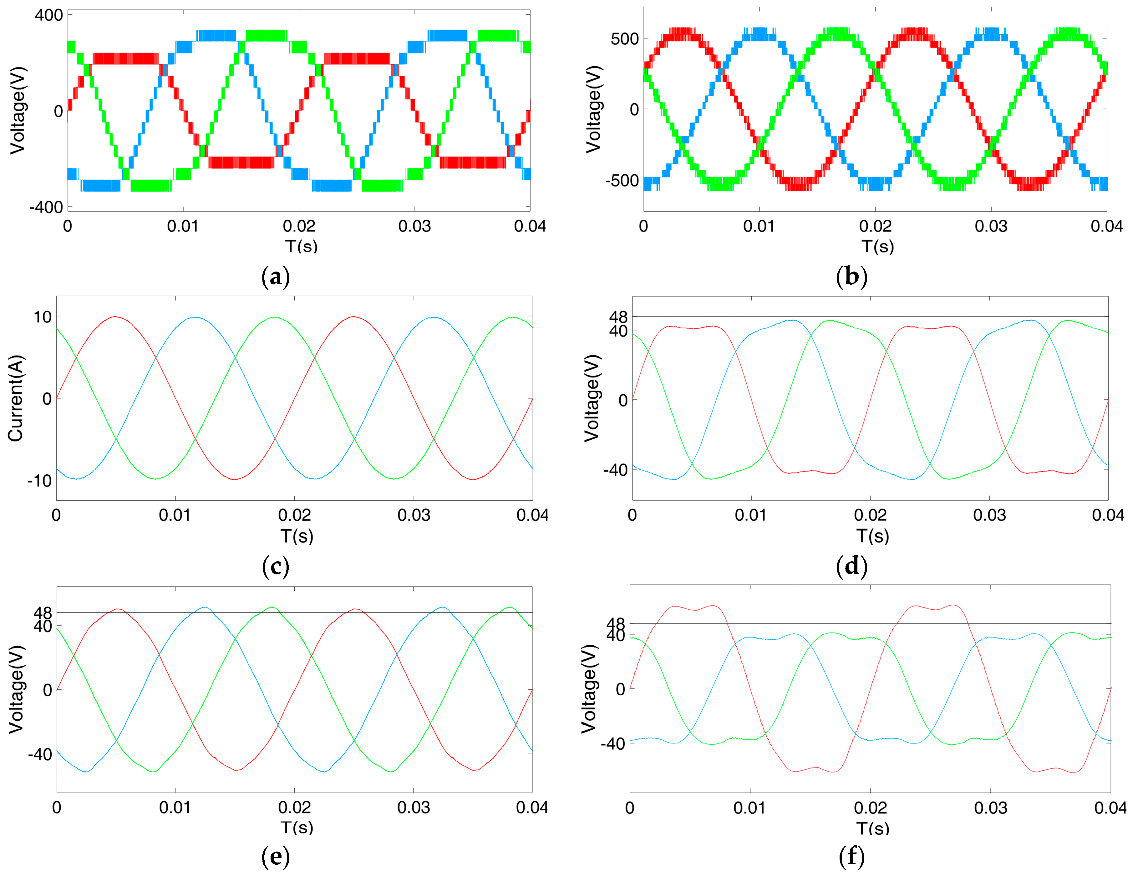
The hybrid control strategy is applied to the “577” operation state, and the results are analyzed (Figure 9). Similarly, upon triggering the hybrid fault-tolerant control strategy, the balanced grid current and converter line voltages (with rated amplitudes and a symmetrical phase shift) are generated when there is great difference among output phase voltages. Figure 9d shows the results of the proposed method in the remaining cells in the three phases. Since there is a phase shift between the fundamental frequency components in Phases B and C after the injection third harmonic, the peak voltages of modulating waveforms increase, owing to a larger km than that in the normal state. The reference waves of submodules in PFSC and the third harmonic injection are shown in Figure 9e,f. It is clear that these two methods, compared with the hybrid compensation method, appear to be less effective in improving battery utilization.
4.2. Experimental Results
In order to verify the reliability of the proposed fault redundancy control schemes in the working operations of FGBESSs, a 10 kVA three-phase eight-module cascade flexible group converter was set up. The experimental platform is shown in Figure 10.
In this setup, a battery pack was connected to the DC link terminal of each H-bridge cell, and the output terminals of the CHB converter (NANTEC, Beijing, China) were connected to the grid via a three-phase inductive load. The power semiconductor devices used in each cell were IXFN230N20T power MOSFETs (IXYS, Milpitas, CA, USA) draining to a source voltage with a rating of 220 V. An XC3S500E Xilinx FPGA (Xilinx, San Jose, CA, USA) was used to implement the PS-PWM method. The proposed fault-tolerant strategies were carried out using the TMS320F28335 Digital Signal Processor (DSP) (TI, Dallas, TX, USA) to control the converter. Eventually, the PWM signals for power devices were generated by TMS320F28035 (TI, Dallas, TX, USA), which were assembled as the central control unit in each cell. The fundamental and switching frequencies of the PS-PWM were 50 Hz and 2 kHz. The parameters of the experimental prototype are shown in Table 4.
According to Equation (17), a smaller fault recovery factor km means a smaller growth in the amplitude of the submodule modulating waveform after a fault occurs. This means a larger fault redundancy margin. The verification of the proposed methods is carried out by experiments in two cases: the “678” state and the “488” state.
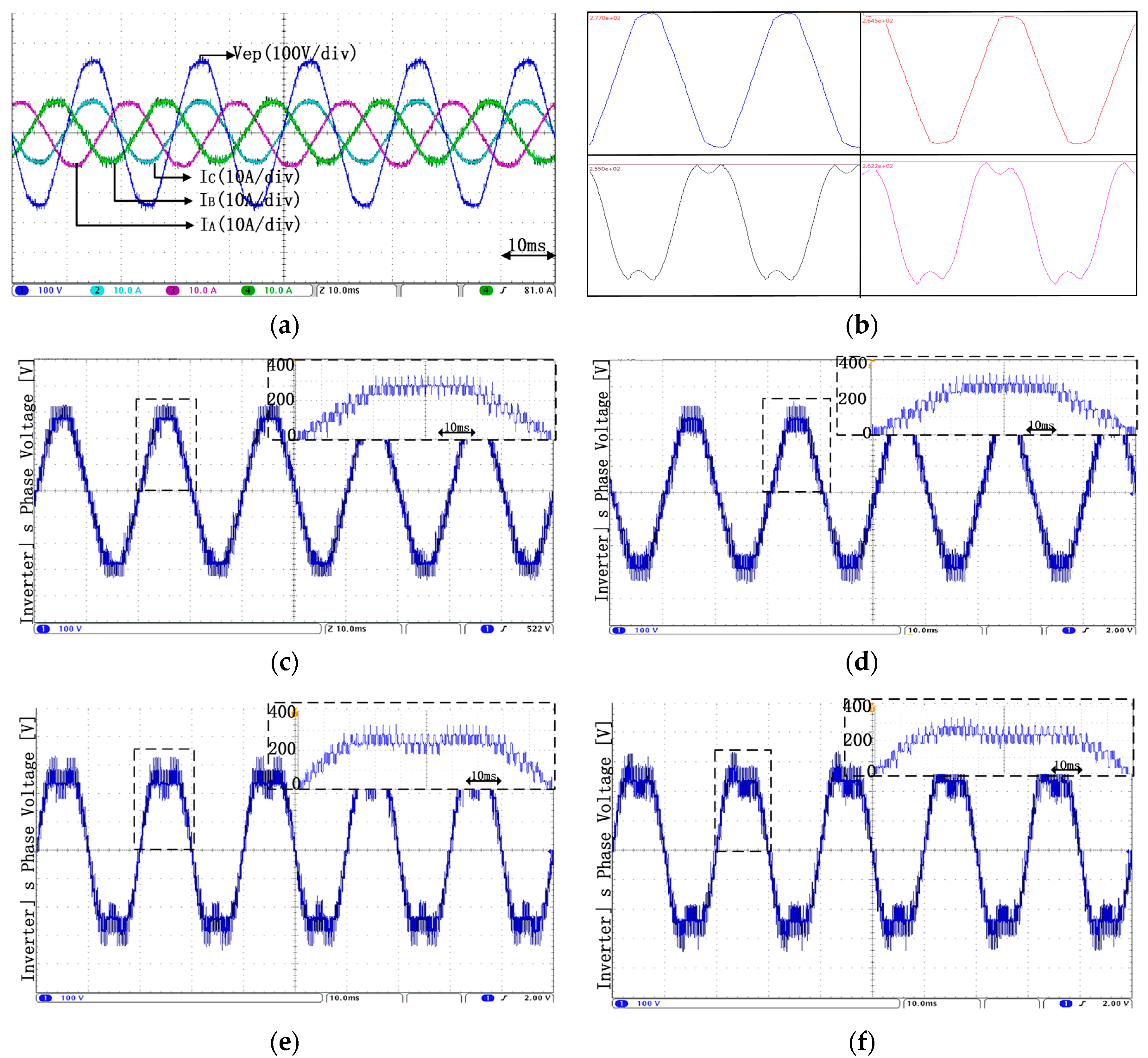
The effects of using different fault-tolerant control methods in the “678” state were analyzed in Case 1. In order to prevent the storage system from experiencing a large switch stress under different fault conditions, the grid voltages were turned down to 240 V. This contributed to a large margin for control strategies with a reduced modulation ratio ma of 0.625. The same balanced grid voltages and currents were generated in various control strategies, as shown in Figure 11a. Based on the conclusion drawn in Section 3.4, the optimal strategy in this condition is the third harmonic injection. The modulation waveforms under different strategies obtained in programming software CCS are shown in Figure 11b. The peak voltage in the third harmonic injection is the smallest, while the other methods obtain larger amplitudes with increasing km. Figure 11c–f represent the AC voltage in Phase B under different control strategies. They indicate that the voltage waveforms are consistent with the modeling signals of different strategies. The experimental results verify the correctness of the conclusion mentioned before.
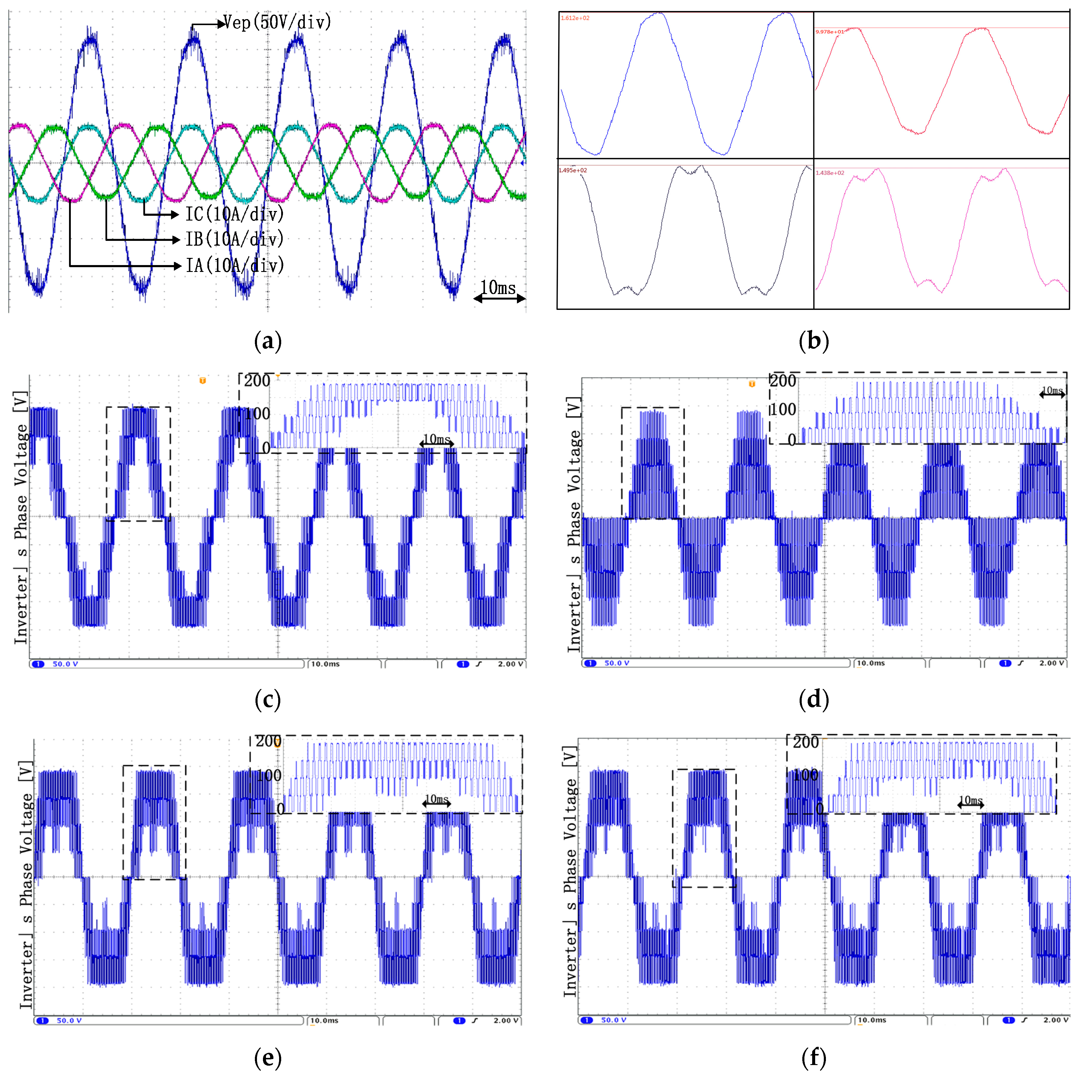
Case 2 shows a comparative analysis of various fault control methods in the “488” state. Similarly, the grid voltage drops to 160 V. The fault methods discussed above generate the same grid voltages and balanced currents, which are shown in Figure 12a. According to Table 3, FPSC obtains the smallest km and the largest fault margin in this condition. This is verified in Figure 12b through the comparison of modulation waveforms of various fault control methods. Figure 12c–f represent the output voltages in Phase A of each redundant control respectively, showing that the output voltages are basically consistent with the modulating voltages.
The above experimental results are in accordance with theoretical analysis, indicating that the proposed redundancy scheme and the related control strategy are correct and effective. The proposed methods are applicable in a high-power energy storage system such as the FGBESS, which potentially makes it a new direction in the control of redundant operation.
5. Conclusions
Fault-tolerant control is necessary for improving post-fault performance in FGBESS. In this paper, a hybrid compensation method has been proposed based on fundamental phase shift compensation and third harmonic injection. For generating the optimal injected third harmonic component in hybrid compensation, the calculation method of the amplitude and initial phase offset of the third harmonic injection in an asymmetrical system under a fault condition is discussed in detail. Meanwhile, by comparing the merits and shortcomings of three fault-tolerant strategies, this paper also analyzed the suitable fault-tolerant conditions of each control method and proposed the optimal solution for each faulty condition that would obtain maximum improvement without over-modulation. Both simulated and experimental results have been presented to validate the feasibility and superiority of the proposed solutions. Apart from the fault-tolerant control strategies for the system, there are other issues related to a flexible group on a control and topology or on a system design level. Further research will focus on the impact of different kinds of batteries on the relationship between packing methods and the optimal fault-tolerant control strategy of each operation in the FGBESS.
Acknowledgments
This work was financially supported by the National Natural Science Foundation of China under Key Program 61633015.
Author Contributions
Junhong Song, Weige Zhang, and Hui Liang conceived and designed the experiments; Hui Liang and Junhong Song performed the experiments; Junhong Song analyzed the data; Hui Liang, Jiuchun Jiang, and Wensong Yu contributed reagents/materials/analysis tools; Junhong Song and Weige Zhang wrote the paper.
Conflicts of Interest
The authors declare no conflict of interest.
Abbreviations
The following abbreviations are used in this manuscript:
| FGBESS | flexible group battery energy storage system |
| SOC | state of charge |
| BESS | battery energy storage system |
| PS-PWM | phase shift pulse width modulation |
| FPSC | fundamental phase shift compensation |
| THI | third harmonic injection |
| THD | total harmonic distortion |
References
- Li, X.; Hui, D. Battery Energy Storage Station (BESS)-Based Smoothing Control of Photovoltaic (PV) and Wind Power Generation Fluctuations. IEEE Trans. Sustain. Energy 2013, 4, 464–473. [Google Scholar] [CrossRef]
- Divya, K.C.; Østergaard, J. Battery energy storage technology for power systems—An overview. Electr. Power Syst. Res. 2009, 79, 511–520. [Google Scholar] [CrossRef]
- Jia, H.; Zhu, J. Design and optimization of a photo-thermal energy conversion model based on polar bear hair. Sol. Energy Mater. Sol. Cells 2017, 159, 345–351. [Google Scholar] [CrossRef]
- Chauhan, A.; Saini, R.P. A review on Integrated Renewable Energy System based power generation for stand-alone applications: Configurations, storage options, sizing methodologies and control. Renew. Sustain. Energy Rev. 2014, 38, 99–120. [Google Scholar] [CrossRef]
- Diao, W.; Jiang, J. Flexible grouping for enhanced energy utilization efficiency in battery energy storage systems. Energies 2016, 9, 498. [Google Scholar] [CrossRef]
- Zheng, Z.; Wang, K. A Hybrid Cascaded Multilevel Converter for Battery Energy Management Applied in Electric Vehicles. IEEE Trans. Power Electron. 2014, 29, 3537–3546. [Google Scholar] [CrossRef]
- Hasan, N.S.; Rosmin, N. Reviews on multilevel converter and modulation techniques. Renew. Sustain. Energy Rev. 2017, 80, 163–174. [Google Scholar] [CrossRef]
- Zhang, W.; Xu, D. Survey on Fault-Tolerant Techniques for Power Electronic Converters. IEEE Trans. Power Electron. 2014, 29, 6319–6331. [Google Scholar] [CrossRef]
- Wen, F. Study on Basic Issues of the Li-Ion Battery Pack Management Technology for Pure Electric Vehicles; Beijing Jiaotong University: Beijing, China, 2009; pp. 8–9. [Google Scholar]
- Ouni, S.; Noroozi, N. A new fault tolerant scheme for cascaded H-Bridge multilevel converter. In Proceedings of the Electric Power and Energy Conversion Systems (EPECS), Istanbul, Turkey, 2–4 October 2013; pp. 1–5. [Google Scholar]
- Moamaei, P.; Mahmoudi, H.; Ahmadi, R. Fault-tolerant operation of cascaded H-Bridge inverters using one redundant cell. In Proceedings of the Power and Energy Conference at Illinois (PECI), Champaign, IL, USA, 20–21 February 2015; pp. 1–5. [Google Scholar]
- Kandasamy, K.; Vilathgamuwa, M. Inter-module state-of-charge balancing and fault-tolerant operation of cascaded H-bridge converter using multi-dimensional modulation for electric vehicle application. IET Power Electron. 2015, 8, 1912–1919. [Google Scholar] [CrossRef]
- Carnielutti, F.; Pinheiro, H. Generalized Carrier-Based Modulation Strategy for Cascaded Multilevel Converters Operating Under Fault Conditions. IEEE Trans. Ind. Electron. 2012, 59, 679–689. [Google Scholar] [CrossRef]
- Wang, L.; Zhang, D. Power and Voltage Balance Control of a Novel Three-Phase Solid-State Transformer Using Multilevel Cascaded H-Bridge Inverters for Microgrid Applications. IEEE Trans. Power Electron. 2016, 31, 3289–3301. [Google Scholar] [CrossRef]
- Chatzinikolaou, E.; Rogers, D.J. Cell SoC Balancing Using a Cascaded Full-Bridge Multilevel Converter in Battery Energy Storage Systems. IEEE Trans. Ind. Electron. 2016, 63, 5394–5402. [Google Scholar] [CrossRef]
- Maharjan, L.; Yamagishi, H.; Akagi, H. Fault-Tolerant Operation of a Battery-Energy-Storage System Based on a Multilevel Cascade PWM Converter With Star Configuration. IEEE Trans. Power Electron. 2010, 25, 2386–2396. [Google Scholar] [CrossRef]
- Prabaharan, N.; Palanisamy, K. A comprehensive review on reduced switch multilevel inverter topologies, modulation techniques and applications. Renew. Sustain. Energy Rev. 2017, 76, 1248–1282. [Google Scholar] [CrossRef]
- Chavarria, J.; Biel, D.; Guinjoan, F.; Meza, C.; Negroni, J.J. Energy-Balance Control of PV Cascaded Multilevel Grid-Connected Inverters Under Level-Shifted and Phase-Shifted PWMs. IEEE Trans. Ind. Electron. 2013, 60, 98–111. [Google Scholar] [CrossRef]
- Yang, X.; Xue, Y. Enhanced Modular Multilevel Converter Based Battery Energy Storage System. In Proceedings of the IEEE Energy Conversion Congress and Exposition (ECCE), Cincinnatti, OH, USA, 1–5 October 2017; pp. 4914–4919. [Google Scholar]
- Wang, T.; Xu, H. Cascaded H-Bridge Multilevel Inverter System Fault Diagnosis Using a PCA and Multiclass Relevance Vector Machine Approach. IEEE Trans. Power Electron. 2015, 30, 7006–7018. [Google Scholar] [CrossRef]
- Deng, F.; Chen, Z. Fault Detection and Localization Method for Modular Multilevel Converters. IEEE Trans. Power Electron. 2015, 30, 2721–2732. [Google Scholar] [CrossRef]
- Wang, T.; Qi, J. Fault diagnosis method based on FFT-RPCA-SVM for Cascaded-Multilevel Inverter. ISA Trans. 2016, 60, 156–163. [Google Scholar] [CrossRef] [PubMed]
- Mahmoudi, H.; Aleenejad, M.; Ahmadi, R. A fault tolerance switching strategy based on modified space vector modulation method for cascaded multilevel converter. In Proceedings of the Power and Energy Conference at Illinois (PECI), Champaign, IL, USA, 23–24 February 2017. [Google Scholar]
- Aleenejad, M.; Mahmoudi, H.; Ahmadi, R. A fault-tolerant strategy based on fundamental phase-shift compensation for three-phase multilevel converters with quasi-Z-source networks with discontinuous input current. IEEE Trans. Power Electron. 2016, 31, 7480–7488. [Google Scholar] [CrossRef]
- Mirafzal, B. Survey of fault-tolerance techniques for three-phase voltage source inverters. IEEE Trans. Ind. Electron. 2014, 61, 5192–5202. [Google Scholar] [CrossRef]
- Abdel-Khalik, A.S.; Masoud, M.I. Improved Flux Pattern With Third Harmonic Injection for Multiphase Induction Machines. IEEE Trans. Power Electron. 2012, 27, 1563–1578. [Google Scholar] [CrossRef]
- Yu, Y.; Konstantinou, G. Power Balance of Cascaded H-Bridge Multilevel Converters for Large-Scale Photovoltaic Integration. IEEE Trans. Power Electron. 2016, 31, 292–303. [Google Scholar] [CrossRef]
- Holmes, D.; Lipo, T.A. Pulse Width Modulation for Power Converters: Principles and Practice, 3rd ed.; Wiley: New York, NY, USA, 2003; pp. 226–230, 270–272. [Google Scholar]
Figure 1.
Construction of a flexible group battery energy storage system.

Figure 2.
Power control block diagram for a flexible group battery energy storage system (FGBESS).

Figure 3.
Fundamental phase shift compensation control block diagram, (a) Output voltages under normal operation; (b) Output voltages after one faulty cell bypassed; (c) Output voltages after modifying phase angles; (d) Output voltages after adding the fault recovery factor.
Figure 3.
Fundamental phase shift compensation control block diagram, (a) Output voltages under normal operation; (b) Output voltages after one faulty cell bypassed; (c) Output voltages after modifying phase angles; (d) Output voltages after adding the fault recovery factor.

Figure 4.
Third harmonic injection control block diagram. (a) Three-phase modulating waveforms in pre-fault and post-fault conditions. (b) Submodule output voltages in Phase A in pre-fault and post-fault conditions.
Figure 4.
Third harmonic injection control block diagram. (a) Three-phase modulating waveforms in pre-fault and post-fault conditions. (b) Submodule output voltages in Phase A in pre-fault and post-fault conditions.

Figure 5.
A hybrid compensation control schematic diagram.

Figure 6.
Waveforms for normal operation: the (a) three-phase converter output voltage; (b) grid current; (c) three-phase total reference signals; (d) three-phase sub-module modulating waveform.
Figure 6.
Waveforms for normal operation: the (a) three-phase converter output voltage; (b) grid current; (c) three-phase total reference signals; (d) three-phase sub-module modulating waveform.

Figure 7.
Waveforms for the “588” operation state with fundamental phase shift compensation (FPSC): the (a) three-phase converter output voltage; (b) three-phase line-to-line voltages; (c) grid current; (d) three-phase sub-module modulating waveform.
Figure 7.
Waveforms for the “588” operation state with fundamental phase shift compensation (FPSC): the (a) three-phase converter output voltage; (b) three-phase line-to-line voltages; (c) grid current; (d) three-phase sub-module modulating waveform.

Figure 8.
Waveforms for the “667” operation state: the (a) three-phase converter output voltage; (b) three-phase line-to-line voltages; (c) grid current; (d) three-phase submodule modulating waveform; (e) grid current in FPSC; (f) three-phase sub-module modulating waveform in FPSC.
Figure 8.
Waveforms for the “667” operation state: the (a) three-phase converter output voltage; (b) three-phase line-to-line voltages; (c) grid current; (d) three-phase submodule modulating waveform; (e) grid current in FPSC; (f) three-phase sub-module modulating waveform in FPSC.


Figure 9.
Waveforms for the “577” operation state: the (a) three-phase converter output voltage; (b) three-phase line-to-line voltages; (c) grid current; (d) three-phase sub-module modulating waveform; (e) three-phase sub-module modulating waveform in FPSC; the (f) three-phase sub-module modulating waveform in the THI.

Figure 10.
Experimental platform of three-phase flexible group converter.

Figure 11.
Experimental results in Case 1: the (a) grid voltages and currents; (b) modulating waveforms under different control strategies; (c) output phase voltages in conventional fault-tolerant control; (d) output phase voltage in FPSC; (e) output phase voltage in the THI; (f) output phase voltage in hybrid compensation control.

Figure 12.
Experimental results in Case 2: the (a) grid voltages and currents; (b) modulating waveforms under different control strategies; (c) output phase voltages in conventional fault-tolerant control; (d) output phase voltage in FPSC; (e) output phase voltage in the THI; (f) output phase voltage in hybrid compensation control.


Table 1.
Phase offset and amplitude of the injected third harmonic under different operation states.
Table 1.
Phase offset and amplitude of the injected third harmonic under different operation states.
| Operation | Maximum Pole Angle | Initial Phase Offset | Amplitude |
|---|---|---|---|
Table 2.
Comparison of different fault-tolerant control strategies.
| Normal | Conventional | FPSC | THI | Hybrid | |
|---|---|---|---|---|---|
| Phase voltage | |||||
| Cell voltage | |||||
| km | --- | 0.866km − km (km is from FPSC) |
Table 3.
Comparison of fault recovery factor of several fault-tolerant control strategies.
| State | Conventional | FPSC | THI | Hybrid |
|---|---|---|---|---|
| 788 | 1.1428 | 1.0455 | 0.9804 | 0.9397 |
| 778 | 1.1428 | 1.0937 | 0.9804 | 0.9912 |
| 688 | 1.3333 | 1.0985 | 1.1438 | 1.0185 |
| 678 | 1.3333 | 1.1690 | 1.1438 | 1.1467 |
| 668 | 1.3333 | 1.2101 | 1.1438 | 1.1507 |
| 677 | 1.3333 | 1.2001 | 1.1438 | 1.0875 |
| 667 | 1.3333 | 1.2619 | 1.1438 | 1.1527 |
| 588 | 1.6 | 1.1538 | 1.3762 | 1.0498 |
| 578 | 1.6 | 1.2151 | 1.3762 | 1.1452 |
| 568 | 1.6 | 1.2903 | 1.3762 | 1.2519 |
| 558 | 1.6 | 1.3899 | 1.3762 | 1.3795 |
| 577 | 1.6 | 1.2707 | 1.3762 | 1.1863 |
| 567 | 1.6 | 1.2813 | 1.3762 | 1.2532 |
| 557 | 1.6 | 1.4326 | 1.3762 | 1.3837 |
| 566 | 1.6 | 1.4104 | 1.3762 | 1.2782 |
| 556 | 1.6 | 1.5006 | 1.3762 | 1.3813 |
| 488 | 2 | 1.2306 | 1.732 | 1.1886 |
Table 4.
Symbols and parameters of the prototype.
| Items | Values |
|---|---|
| Rated Apparent Output Power | 10 kVA |
| Rated AC Voltage (Us) | 311 V |
| SM Number Per Phase (N) | 8 |
| Filtering Inductor (LA,B,C) | 1 mH |
| SM Capacitor (Cm) | 2200 uF |
| Rated SM Battery Voltage (UB) | 48 V |
| SM PWM Carrier Frequency (fs) | 2 kHz |
| Equivalent Switching Frequency | 32 kHz |
© 2018 by the authors. Licensee MDPI, Basel, Switzerland. This article is an open access article distributed under the terms and conditions of the Creative Commons Attribution (CC BY) license (http://creativecommons.org/licenses/by/4.0/).
Share and Cite
MDPI and ACS Style
Song, J.; Zhang, W.; Liang, H.; Jiang, J.; Yu, W. Fault-Tolerant Control for a Flexible Group Battery Energy Storage System Based on Cascaded Multilevel Converters. Energies 2018, 11, 171. https://doi.org/10.3390/en11010171
AMA Style
Song J, Zhang W, Liang H, Jiang J, Yu W. Fault-Tolerant Control for a Flexible Group Battery Energy Storage System Based on Cascaded Multilevel Converters. Energies. 2018; 11(1):171. https://doi.org/10.3390/en11010171
Chicago/Turabian StyleSong, Junhong, Weige Zhang, Hui Liang, Jiuchun Jiang, and Wensong Yu. 2018. "Fault-Tolerant Control for a Flexible Group Battery Energy Storage System Based on Cascaded Multilevel Converters" Energies 11, no. 1: 171. https://doi.org/10.3390/en11010171
Note that from the first issue of 2016, this journal uses article numbers instead of page numbers. See further details here.