Combined Supporting Technology with Bolt-Grouting and Floor Pressure-Relief for Deep Chamber: An Underground Coal Mine Case Study

1
School of Energy Science and Engineering, Henan Polytechnic University, Jiaozuo 454000, China
2
Xinzhuang Coal Mine, Henan Shenhuo Coal and Electricity Co., Ltd., Yongcheng 476600, China
3
Tian’an Coal Mining Company Limited of Pingdingshan City, Pingdingshan 467000, China
*
Author to whom correspondence should be addressed.
Energies 2018, 11(1), 67; https://doi.org/10.3390/en11010067
Submission received: 5 October 2017
/
Revised: 7 November 2017
/
Accepted: 21 November 2017
/
Published: 1 January 2018
Abstract
:Based on the engineering geological conditions of the Number 2 chamber in the slope at Xinzhuang coal mine, which is located in the eastern part of Yongcheng City, Henan Province, China, the authors conducted a systematic research on the anchoring-grouting and the floor pressure-relief supporting technology by using theoretical analysis, numerical calculation and field industrial test. Results showed that: (1) the lithology of the surrounding rock was poor, and the stress and effective loading coefficient on the chamber surrounding rock were high due to the abutment pressure that was induced by the shaft protective pillar. Both of them resulted in the floor heave and the surrounding rock deformation damage of the chamber; (2) The numerical calculation showed that, after the floor pressure-relief slot was excavated in the head chamber, the vertical stress of the floor surrounding rock of chamber and the horizontal stress of the side surrounding rock were significantly reduced when compared with the stress before the pressure-relief, and the floor vertical displacement basically remained unchanged. So the floor pressure-relief slot could effectively control the chamber floor heave and was helpful for the long-term stability of the chamber. After the severe deformation chamber was renovated by using a combined support with bolt-mesh-shotcreting and anchor cables, several other techniques were also applied to ensure the stability of the chamber. The floor pressure-relief slot was excavated, both the roof and the sides surrounding rock of chamber were grouted with grouting bolt, and both sides and the floor (including pressure-relief slot) of the chamber were grouted with anchor cable bundles. After implementation of above systematic techniques, the surrounding rock of chamber is in a stable state, which demonstrated that the field test is successful. The combined supporting technology with the anchoring-grouting and the floor pressure-relief has an important practical significance for the long-term stability of the chamber to ensure the safe and efficient production of the mine.
1. Introduction
With the construction of the large coal production bases and the safety and high efficiency modern coal mines in China, the mining intensity increases and the mining depth gradually develops to deep ground. Deep mining activities require a large scale automatic underground belt conveyor. However, the strength of the surrounding rock of the belt conveyor chamber is lower because the chamber is generally located in the weak coal measure rock strata. The stress near the chamber is highly concentrated because of the mining activities. The above factors make it very hard to control the deformation of surrounding rock of the deep chamber, and almost not possible to ensure the stability and the service life of the chamber.
As a support technology in underground mining engineering, bolting has been used for more than 100 years since 1912 [1,2]. In the past 20 years, new bolt support technology develops very fast in China, which includes the supporting theory, supporting materials, design methods, and monitoring technologies. Indraratna [3] studied the fracture mechanism of surrounding rock in the circular roadway under bolting support by conducting model tests. Bobet and Einstein [4] proposed the mechanical analysis model of surrounding rocks under bolt support based on the elastic-plastic theory. Kang et al. [5] analyzed the breakup mode and reason of non-full-length anchoring bolt based on field monitoring; they proposed related improvement measures and conducted field applications. In China, the proportions of bolt support in coal roadways have reached more than 60%. Field practices indicate that applying high pretension and intensive bolts with the cooperating the grouting reinforcement is an effective technique to control roadway deformation, especially in kilometer-depth roadways, soft rock roadways, soft-broken roadways, and roadways that are affected by dynamic mining pressure [6,7,8]. According to the Velenje coal mine geological condition, Vižintin studied rock burst dependency on the type of steel arch support, coal burst source locations and the development of dewatering predictions, their results have important directive to production practices of Velenje coal mine [9,10,11]. Cai et al. [12] studied a serious deformed chamber near the panel area, which was strongly affected by both ground pressure and dynamic mining activities. They applied an integrated combined technique to control the deformation of the chamber, such as the filling chemical pulp in the roof and sides surrounding rock of chamber, the backfill grouting with cement, and the constructing prestress full length chemical grouting anchor cable with anchor cable grouting in the floor. Meng et al. [13] studied geological conditions of the shaft station chamber, whose surrounding rocks are of low strength and high stress in the Zhaolou coal mine. They put forward a combined support system of “three anchors” to control deep roadway surrounding rock deformation and floor heave, which adopted grouting bolts as the core including bolt, cable anchor and bolt-grouting. Gao et al. [14] researched the supporting mechanism of three-dimensional (3D) anchor-cable and applied the 3D anchor-cable in supporting coal seam roadways. After the pressure relief on both sides of the roadway, the 3D anchor-cable support technology solves the roadway support problem in the soft thick coal seam. Based on the in situ stress distribution characteristics of the chamber, Zhang et al. [15] showed that the vertical stress and shear stress are two main causes for the deformation and failure of the roadway under dynamic pressures. They suggested that keeping a reasonable protective coal pillar and applying deep hole loosening (pressure relief) blasting of surrounding rock are good ways to control the roadway deformation. LI [16] believed that bolt breakup in high stress surrounding rock was caused by the joint action of tensile and shear stress based on field measurement and analysis. Shen et al. [17] researched the deformation of the deep large section soft rock substation chamber. By arranging pressure-relief bores in the sides of the chamber, opening the pressure-relief slot in the floor, and applying a combined support technology of bolt (cable) strengthening the chamber floor surrounding rock, they could effectively control the deformation of the chamber. According to the supporting mechanism of “strong-weak-strong structure”, Yang et al. [18] solved the high stress roadway floor heave problem by arranging pressure-relief slot in the middle of floor and using the two blasting method to construct pressure-relief slot in the middle of the floor on the basis of the high strength support principle in roadways. This method improves the digging efficiency of the pressure-relief slot and solves the construction problem of the pressure-relief slot. Chen et al. [19] put forward the deep soft rock roadway full section unloading support technology by using high strength prestress yieldable anchor cables and floor pressure-relief slots.
Xinzhuang coal mine is located in the eastern part of Yongcheng City, Henan Province, China (Figure 1). There are four belt conveyor transportations in the main blind incline shaft of Xinzhuangcoal mine, which belong to Henan Shenhuo Coal and Electric Power Corporation Ltd. (Shangqiu, Henan, China). The second head chamber with a large section is located in the No.II-2 coal seam, and its roof strata and surrounding rocks are weak. The chamber has been served for more than ten years. Due to the influence of the blind incline shaft’s protective pillar, the chamber deforms seriously, the floor is broken, and both rib sides converge seriously. This causes the bending of the lifting beam in the upper chamber where the arch height is around 400 mm. Since the second head chamber has to provide transport services for deep second and third level until the mine is abandoned, the stability of head chamber must be ensured, which directly controls the safe operation of the belt conveyor and the daily production of the mine. The study of the head chamber deformation and the broken mechanism of surrounding rock by using bolting grouting reinforcement and floor pressure-relief technology could provide a reference for the surrounding rock deformation control in the deep third and fourth head chamber.
2. Geological Engineering Condition of Head Chamber
Xinzhuang coal mine is located in the eastern part of the Huanghuai alluvial plain, the southern margin of the old course of the Yellow River, the land is flat, and the ground elevation is +31 m. The overall shape of Xinzhuang area is a monoclinic tectonic, which is inclined to the north, and the strata occurrence is gentle and tectonic is relatively stable with lots of faults. The complexity of the tectonic movement is medium. The mine uses shaft multi-level uphill and downhill development method. The first, second, and third mining level of mining is at −380 m, −600 m, and −700 m, respectively. The current production level is at the third level. The inclined longwall retreat mining method is used to mine the Permian No.II-2 coal seam. The coal seam dips 3−10°, and the thickness is 1.45–3.40 m with an average of 3.0 m. The coal seam structure is simple with no partings, which belongs to the stable seam. The roof is mainly sandy mudstone or medium fine grained sandstone, sometimes mudstone, and the floor is mudstone or sandy mudstone.
The first level of Xinzhuang coal mine uses shaft development, and the second and third level uses blind incline shaft development. The four blind incline shafts are shown as follows: belt blind incline shaft, track blind incline shaft, pedestrian blind incline shaft, and return air blind incline shaft, and all of them were arranged along the No.II-2 coal seam. The belt blind incline shaft between −380 m level to −600 m level has two powerful belt conveyors, and the second powerful belt conveyor head chamber is arranged along the floor of No.II-2 coal seam. The depth of the chamber is 526 m. The original design section of the chamber is the three heart arch type, and the width, height and full length are 6.7–7.4 m, 5.3 m, and 17.7 m, respectively. A combined supporting technique, including bolt, anchor cable, bolt-mesh, and shotcreting were used to support the chamber. After several renovations, the surrounding rocks of chamber are already broken.
3. Main Causes of Surrounding Rock Deformation in the Head Chamber
The deformation behavior of roadway in the second head chamber was measured continuously and measured results show that the chamber rib-to-rib moves with a speed of 36.4 mm/month, and the floor heave moves with a speed of 8.7 mm/month. When the chamber floor heave reaches a certain value, the motor foundation will tilt. This will induce the dislocation or fracture between the connecting shaft of the conveyor motor and the gearbox in the chamber, which causes serious accidents of downtime outages and equipment damage. These potential damages could stop the mine operation, and therefore requires preventions. At present, the head chamber surrounding rock has serious deformations, and the main reasons are summarized as follows:
- (1)
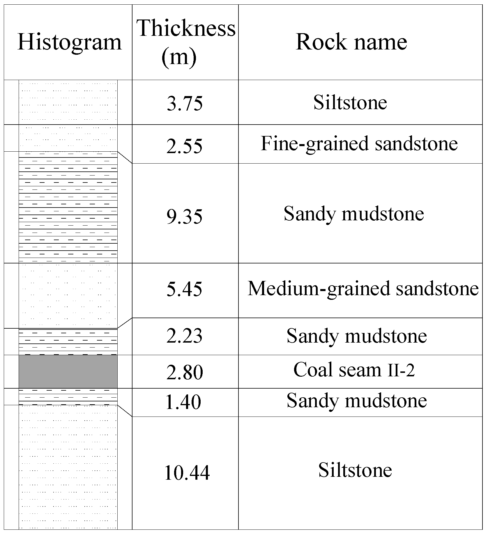
- Chamber surrounding rocks are weak lithology and of low strength. The chamber is located in the roof-to-floor strata of the coal seam, and the lithology of surrounding rocks is mainly coal seam, sandy mudstone, and sandstone. According to the observation of the exposure surface during the chamber driving and drilling, the integrated histogram of surrounding rock of chamber is shown in Figure 2.
- (2)
- Buried depth of the chamber is 526 m with a high in situ stress.
- (3)
- The chamber was affected by the fixed abutment pressure of the shaft protective pillars. The inclined longwall working face is completed in both sides of the blind incline shaft, and the chamber is in the downhill of the protective pillars of the blind incline shaft with a pillar total width of 570 m.
The roadway surrounding rock stability and deformation state is largely dependent on the surrounding rock stress and the strength under certain support conditions. The surrounding rock effective load coefficient C can reflect the stability, the loose circle’s size, and the deformation characteristics of the surrounding rock under the specific conditions of buried depth, lithology, and mining conditions [20,21].
where, K is the coefficient of stress concentration of surrounding rock. When the virgin stress of rock is the gravity stress, K is 1; under the influence of mining activities, K is 1.3. γ is the average bulk density of overlying strata, N/m3; H is the buried depth of the roadway, m; and, R0 is the uniaxial compressive strength of surrounding rock, MPa.
According to the literature [21], the roadway is under the influence of the fixed abutment pressure, when surrounding rock effective load coefficient is constant and the roadway surrounding rock deformation velocity changes within a certain range. The relationship between the surrounding rock average deformation velocity V and effective load coefficient C is shown as follows [21]:
where V is average roof-to-floor convergence speed of the roadway, mm/day.
Based on the surrounding rock mechanics parameters and geological conditions of the head chamber in Xinzhuang coal mine, the surrounding rock deformation velocity is shown below:
The deformation of the head chamber surrounding rock was monitored and the results show that the average speed of the floor heave is 0.3 mm/day. These results using an effective load coefficient to forecast the roadway surrounding rock deformation speed are consistent with the measured values.
4. Pressure-Relief Principle of Chamber Floor Pressure-Relief Slot
Most coal mines in China use top pressure-relief slot or large-scale pressure-relief to protect the chamber [22]. This method could keep the surrounding rock of the chamber integrate and make the chamber stay in a stress reduction zone, which makes the surrounding rock remain table for a long time. Xinzhuang coal mine is a large scale production mine, and this requires that the downtime of production should be minimized or the renovation should be carried out only in the maintenance time. When considering that there is no shipped out system of the gangue in the mine, the floor pressure-relief slot is used to control the chamber floor heave after the chamber is renovated by the surrounding rock bolt-grouting technique.
4.1. Pressure-Relief Principle and the Layout and Parameters of the Chamber Pressure-Relief Slot
4.1.1. Pressure-Relief Principle of Floor Pressure-Relief Slot
First, the “high strength, strong pressure, integration” bolting and grouting combined support is applied in the roof and two-side of the chamber to control the stability of the surrounding rock. After the pressure-relief slot is excavated in the chamber floor, a “weak structure” will be formed in the floor, which can reserve certain space for the chamber floor to heave and therefore release the floor high concentrated stress. The “weak structure” could control the stress release in chamber floor, absorb a large amount of surrounding rock deformation, and change the distribution of the chamber surrounding rock stress field. This also means the peak stress of the surrounding rock near the chamber was transferred to a long distance rock area, which makes the chamber is in the stress decreasing area, and thus achieves the purpose of unloading. Meanwhile, the grouting reinforcement was adopted to control the stability of the floor and two-side of the chamber. After the high stress of chamber surrounding rock is released, a low stress will appear, which is gradually balanced by the grouting support. At the same time, the chamber enters a relatively stable stage. A long term effective control of the chamber surrounding rock can be realized when the bolting and grouting support parameters and the floor pressure-relief slot designed parameters of the chamber surrounding rock are reasonably designed [18].
4.1.2. Layout and Parameters of Pressure-Relief Slot
The layout and parameters of the pressure-relief slot directly determine the pressure-relief effect of the chamber. Arranging the pressure-relief slot in both sides of the chamber floor can effectively change the stress field of the surrounding rock, reduce surrounding rock stress concentration, and thus achieve the prevention of the chamber floor heave [23].
The head chamber floor is the pouring concrete base of 1#, 2#, 3#, 4# belt conveyor motor and reducer unit, which were laid in a double row along the length direction of the chamber. The unit base of 1# and 2# are a whole base and so did the 3# and 4#, as shown in Figure 3. Along the length direction of the chamber is 4.555 m, the distance between the base and the chamber is 0.6–0.9 m, and the base depth is 1.5 m. Therefore, the chamber floor pressure-relief slot can only be laid on both sides of the chamber floor.
The depth of the pressure-relief slot in general is 0.9–2.0 m [24,25] in the examples of successful treatment of floor heave in the deep chamber by the floor pressure-relief slot in China. If the excavation of the pressure-relief slot depth is too large due to the slotting, the floor heave amount that is caused by the increase plastic zone of the floor surrounding rock will exceed the adsorbed limit floor deformation by the pressure-relief slot. Therefore, the floor pressure-relief slot should have a reasonable depth. When considering that the depth of the pressure-relief slot must be equal to or at least exceed the depth of the nose concrete base, the pressure-relief slot width and depth were determined as 0.4 m and 1.5 m, and the length of the pressure-relief slot is the chamber length.
In the following section, we will simulate the stress field of the chamber surrounding rock before and after the implementation of the pressure-relief slot by numerical simulation using FLAC3D. FlAC3D is a numerical modeling package for geotechnical analyses of soil, rock, constructs, and ground support, which has been widely used in the mining industry [26,27]. The analysis of the FLAC3D modeling results could be helpful to explain the pressure-relief mechanism of the floor pressure-relief slot.
4.2. Chamber Deformation Calculation Model When Opening the Floor Pressure-Relief Slot
4.2.1. Numerical Computational Mechanics Model
In the middle of the blind incline shaft head chamber in Xinzhuang coal mine, the section width along the strike direction of the coal seam is selected as the numerical calculation model, as shown in Figure 4. The model’s horizontal and height dimensions are 58 m and 50 m, respectively; both sides of the model have supported boundary, the amount of displacement in the x direction is zero, and the bottom edge of the model is the fixed boundary. The upper part of the model is a free surface by applying an area force that is the gravity of the simulated upper strata. Chamber buried depth is 526 m, and an average bulk density of overlying rock mass is 2.5 × 10⁴ N/m3. When considering that the vertical virgin stress of chamber surrounding rock is the self-weight stress, lateral pressure coefficient λ is 1.5, and the virgin stress of chamber surrounding rock is as follows: vertical stress σz:σz = γH = 0.025 × 526 = 13.15 (MPa), so q = σz = 13.15 (MPa) in Figure 4; horizontal stress σx:σx = σy = λσz = 1.5 × 13.15 = 19.725 (MPa).
Chamber is designed to an arched section, and the chamber width is 6.7 m and the height is 5.4 m. The model grid is 112 × 40 × 100. The pressure-relief slot on both sides of the chamber floor is designed to rectangular section, and the specification is 0.4 m × 1.5m.
The following assumptions are made for numerical calculations in order to simplify the simulation: (1) the influence of construction process on rock mechanics index is not considered, and the seepage influence is not considered either; (2) Mohr-Coulomb strength criterion is adopted as the constitutive model of the rock mass; (3) The calculation process is shown as follows. Firstly, the rock mass will reach the initial equilibrium in the state of original stress of rock. Then, the initial displacement amount is set to zero, and the excavation part of the roadway is replaced by the null model. Finally, the displacement and stress values after the change are calculated.
4.2.2. Physical and Mechanical Parameters of Chamber Surrounding Rock
The physical and mechanical parameters of the surrounding rock are very important for determining the simulation result of the chamber. According to the surrounding rock geological conditions near the head chamber in Xinzhuang coal mine, the physical and mechanical parameters of the chamber surrounding rock are obtained by the indoor rock and coal mechanical tests with a reasonable reduction coefficient. All of these obtained parameters are shown in Table 1.
4.3. Analysis on Numerical Simulation Calculation Results
Based on numerical simulation results, the comparative analysis of the pressure-relief effect of the pressure-relief slot can be obtained by analyzing the changes of the vertical stress field, the vertical displacement field, the horizontal stress field, and the horizontal displacement field of the chamber surrounding rock before and after the pressure-relief.
4.3.1. Numerical Computational Mechanics Model
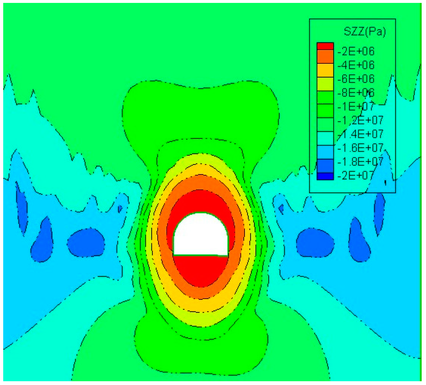
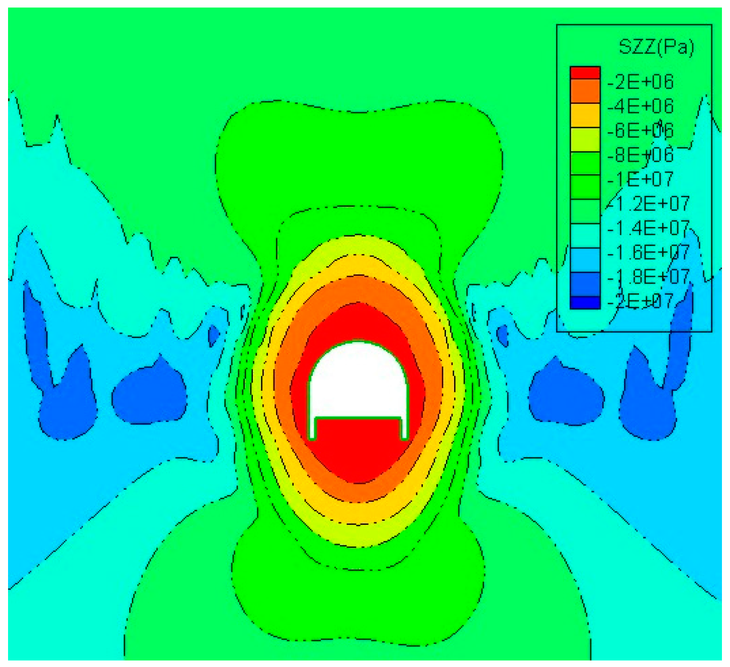
Figure 5 and Figure 6 show the vertical stress field of the surrounding rock of the chamber before and after the opening of the floor pressure-relief slot. In the central vertical direction of the chamber, the observation points were selected in the surrounding rock at the roof and floor. The displacement and stress changes of each observation point are compared before and after the pressure relief.
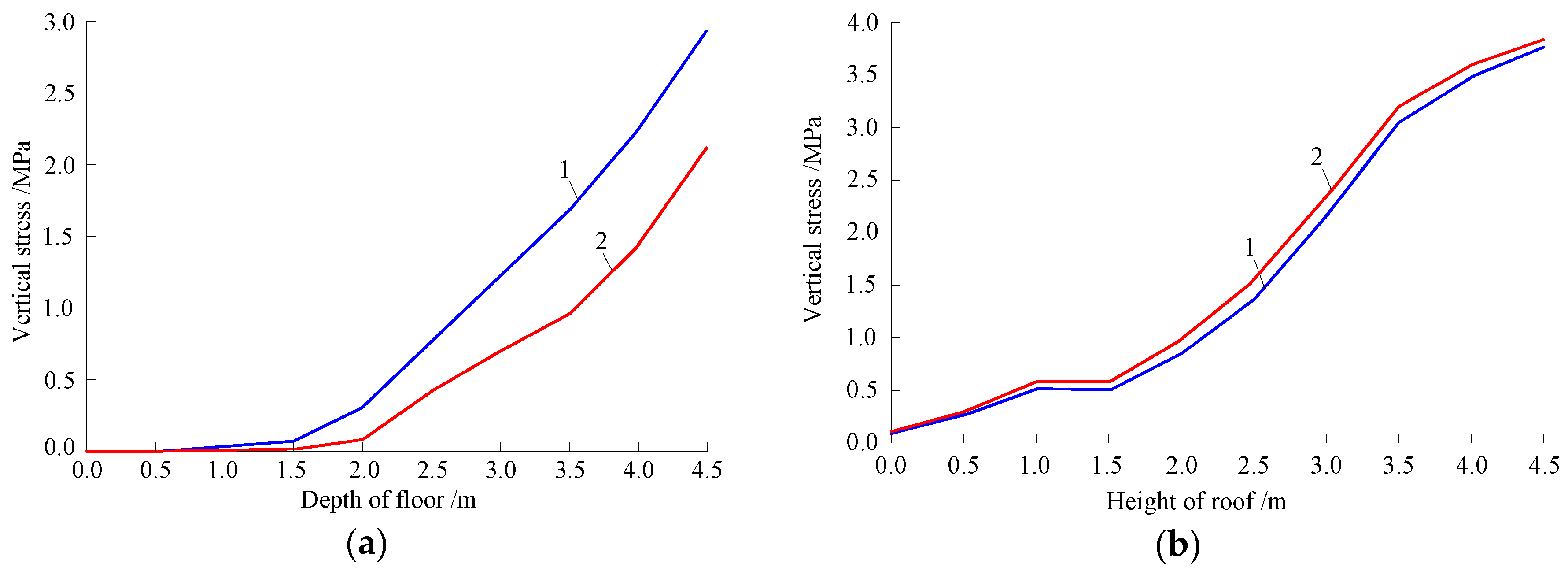
The vertical stress distribution curves of the surrounding rock of the chamber are shown in Figure 7. When compared with the stress before the pressure-relief, the vertical stress of the chamber floor at the same depth decreases slightly and the vertical stress of the chamber roof at the same height slightly increases. When compared with the stress prior to the pressure-relief, the vertical stress of surrounding rock at the 1.5 m range of the chamber floor is slightly smaller after the pressure-relief, the vertical stress of surrounding rock at the 1.5 m–4.5 m range of the chamber floor average decreases up to 41%, and the vertical stress of surrounding rock of the chamber roof changes little.
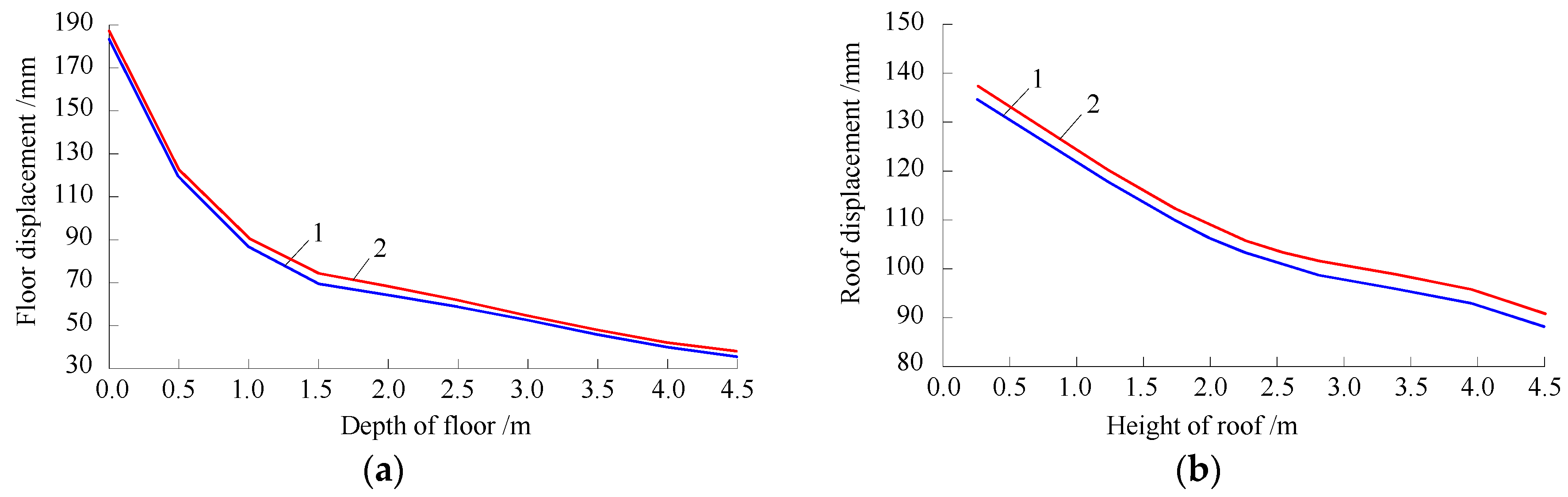
The vertical displacement curves of the surrounding rock of the chamber before and after the pressure-relief are shown in Figure 8. When compared with the displacement before the pressure-relief, the vertical displacement of the chamber floor at the same depth basically remains unchanged after the pressure-relief, and the vertical displacement of the chamber roof of the same height slightly increases with an average of 3.1%. These results show that the vertical stress of the surrounding rock of the chamber floor is greatly reduced, and the floor vertical displacement basically remains unchanged after the open of the pressure-relief slot. This is very helpful for the long-term stability of the surrounding rock of the chamber floor.
4.3.2. Changes of the Horizontal Stress Field and Displacement Field of the Chamber
Figure 9 and Figure 10 show the horizontal stress distribution of the surrounding rock of chamber before and after the opening of the pressure-relief slot in the floor. In order to study the change of the horizontal stress, a horizontal observation line is arranged at the 2 m high position of the chamber, and the observation points are selected at different depths from the surface of the chamber. The variation of the horizontal stress and displacement of the surrounding rock of the chamber are studied.
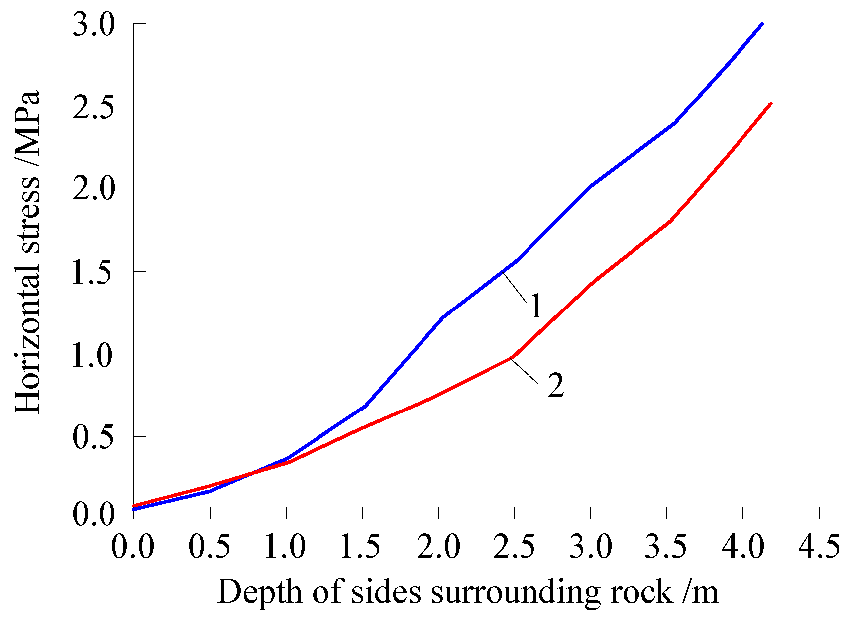
Figure 11 shows the horizontal stress distribution curve of the chamber surrounding rock before and after the pressure-relief. As compared with the stress before the pressure-relief, the horizontal stress of both sides of the chamber is reduced after the pressure-relief, and the high stress is transferred to the deep surrounding rock. The horizontal stress of the surrounding rock at the 1.2 m range of both sides of the chamber changes a little after the pressure relief, but the average decrease of the stress at the 1.2–4.5 m range is 30%. Figure 12 shows the horizontal displacement distribution of the surrounding rock of the chamber before and after the pressure-relief. When compared with the displacement before the pressure-relief, the horizontal displacement of both sides of the chamber is increased by an average of 3.7% after the pressure-relief. These results show that the horizontal stress of both sides of the chamber is greatly reduced, and that the horizontal displacement of both sides of the chamber changes little, this is conducive to the stability of the surrounding rock of both sides of the chamber.
To sum up, the opening of the floor pressure-relief slot can effectively control the chamber floor heaven and has an important significance to ensure the long-term stability of the chamber floor.
5. Bolt-Grouting Reinforcement of Chamber and Pressure-Relief Industrial Test
According to the deformation and failure of the surrounding rock of the head chamber, the treatment of chamber deformation is carried out in three steps by using the available construction technology. Firstly, the bolt (cable)-mesh-shotcreting combined support is applied. The chamber is renovated by expanding both sides, ripping the roof, and cleaning the floor. After the expansion of the chamber, the combined support of bolting, anchored cable, bolting, and metal mesh, and shotcreting are implemented. Secondly, the grouting reinforcement of the chamber roof in the shallow surrounding rock and opening the floor pressure-relief slot is implemented. After the chamber is renovated, the grouting by grouting bolt and constructing pressure-relief slot on both sides of the chamber floor is applied. Thirdly, the grouting reinforcement of the chamber sides and the floor deep surrounding rock are carried out. The grouting anchor cable bundle is used to reinforce the chamber sides and the floor surrounding rock and ensure the long-term stability of the chamber.
5.1. Anchoring-Grouting Support and the Floor Pressure-Relief Slot Construction
First of all, the chamber section is expanded. After the expansion of the chamber meets the design specifications, the steel mesh is laid and then the bolt, metal mesh, and initial shotcreting support are all applied. Then, both the anchored cable and the secondary shotcreting support are carried out. After the bolt-cable-mesh-shotcreting support is completed, the chamber sides and roof shallow surrounding rock is grouted by a grouting bolt. After constructing the pressure-relief slot on both sides of the chamber floor, the chamber sides and floor deep surrounding rock is grouted by the grouting anchor cable bundle. The layout plane drawing and sectional drawing of the chamber with anchoring-grouting support are shown in Figure 13 and Figure 14.
(1) The bolt mesh cable and shotcreting support. The bolts in the roof and sides of the chamber are Φ20 mm × 2200 mm resin bolt, and the spacing and inter-row distances is 1400 mm× 700 mm. The distance between the orifice of bottom corner bolt and the floor is 200 mm, and the downward inclination of the bolt is 30°. The bolt anchorage agent is MSK2335 type resin drug roll, and each hole has three drug rolls. The bolt is symmetrically arranged along the center of the chamber roof with 10 bolts per row, and the bolt anchoring force is not less than 10 t. The bolt plate is the steel pallet with 10 mm thick. The anchored cable is symmetrically arranged along the chamber center line with nine anchored cables per row using Φ17.8 mm × 8000 mm single steel strand. The anchored cable is arranged in the middle of two bolts and the spacing and inter-row distance is 1400 mm × 700 mm. The anchorage agent is MSK2335 type resin drug roll, and each hole has six drug rolls. The pre-stress is not less than 20 t, which is accomplished by pretensioning. The anchored cable plate is the steel plate whose specification is 200 mm × 200 mm × 20 mm. After installing the bolt and metal mesh, bolt and anchored cable, the first shotcreting is carried out with a spray layer thickness of 30–50 mm. After first shotcreting, the combined support of bolt and the reinforced mesh is carried out. The bolting and metal mesh is 2 m × 0.9 m reinforced mesh. The secondary spray layer thickness is 100 mm and the final is 200 mm. Water is sprinkled on the grouting surface for maintenance after the shotcreting.
(2) The pressure-relief slot is constructed on both sides of the chamber floor. After the chamber is expanded and the bolt-mesh-shotcreting supports are completed, the pressure-relief slot is symmetrically constructed on both sides of the chamber floor by pneumatic picks, and the length of the pressure-relief slot is the same as the length of the chamber. The width of pressure-relief slot is 0.4 m and the depth is 1.5 m. Angle steel welded rectangular bracket is used to support the upper laying belt in the pressure-relief slot, and the pressure-relief slot is completely sealed.
(3) Chamber sides and roof shallow surrounding rock are grouted by grouting bolt. Firstly, drilling of the grouting bolt is constructed in the chamber sides and roof, and the grouting bolt is installed. The specification of the grouting bolt is Φ20 mm × 2500 mm, and the spacing and inter-row distances is 2000 mm × 2000 mm. The diameter of grouting drilling is 28 mm, and the depth of drilling is 6 m. The bolt is installed by the MQT-120 pneumatic bolt drilling machine, which is entangled by the seal with hemp rope, and the exposed length of grouting bolt is 200 mm. Concentrated grouting are installed after all of the grouting bolts are completed. The Grouting machine model is 2TJZ-60/210, the grouting material is PC32.5 grade cement, and water-cement ratio is 1:4.8. When the grouting pressure reaches 3 MPa, the grouting is stopped.
(4) Chamber sides and floor and pressure-relief slot deep surrounding rock are grouted by grouting anchor cable bundle. The construction of one row drillings of grouting anchor cable bundle is in chamber sides and the construction of the 4 rows is in floor (including pressure-relief slot). One-time concentrated grouting after the adjacent 8–10 anchor cable bundle are installed.
The grouting anchor cable bundle consists of three steel strands with the diameter of 7.8 mm and the length of 8 m, and three anchored cables share one tray. The anchor cable bundle fixed baffle are installed in a proper order of 1m spacing starting from 2.5 m at one end of the steel strand along the length direction of the anchor cable bundle. Three steel strands are separated evenly, and the three steel strands are fixed together by iron wire in the middle of the adjacent fixed baffle. In this way, the anchor cable bundle shows a bubble type distribution structure and increases the anchoring force and the elongation property of anchor cable bundle [28]. The drilling diameter of the grouting anchor cable bundle is 108 mm, and the depth of drilling is 6 m. The spacing and inter-row distances of floor drilling is 1.5 m × 1.5 m. The orifice of the grouting anchor cable bundle of chamber sides are located 0.4 m above the floor, drilling direction and the roadside downward tilt are at an angle of 65°, and the drilling spacing is 1.5 m.
The grout anchorage cables drilling borehole is constructed by the TXU-75A drilling machine, and the casing pipes with a diameter of 108 mm and length of 2 m are installed in the drilling orifice. The external aperture of the casing pipe opening wire is convenient for the grouting construction of anchor cable bundle. The external aperture casing head is in parallel with chamber wall (or floor) to ensure that the anchor cable bundle tray can be cling to chamber wall or floor. After the construction of the anchor cable bundle drilling, the field assembled anchor cable bundle is installed in their proper places. Before the grouting of anchor cable bundle is drilled, a certain amount of gray sand dry material (ratio of fine sand and meters of stone is 1:2) is poured in each anchor cable bundle drilling borehole, and then the grouting construction is initiated. After the end of the anchor cable bundle drilling grouting, and the waiting time of three or four days for solidification, the installation of prestress anchor cable bundle tray is initiated to make sure the pretightening force of the anchor cable bundle reaches 60 t.
5.2. Bolt-Grouting Reinforcement and Floor Pressure-Relief Effect
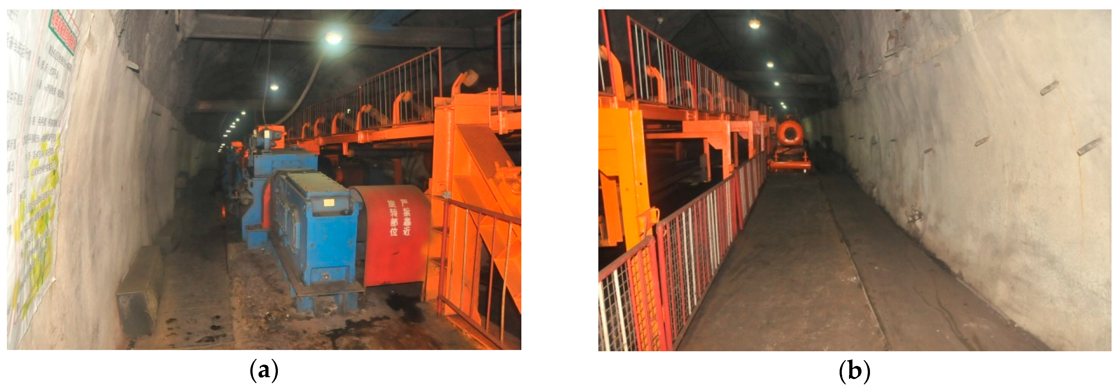
The deformation and failure of the chamber surrounding rock before renovation are shown in Figure 15. The space of the chamber is narrow, which affects the safe and daily operation of the electromotor and the upper belt of the belt conveyor in the chamber. This is shown through the normal parallel connection between the reducer box shaft and belt drive axle, which needs to be adjusted and maintained every quarter. During the maintenance, the production of the mine and belt has to be stopped. After the whole bolt-grouting reinforcement and the application of the pressure-relief, the chamber support situation has been primarily improved, as shown in Figure 16.
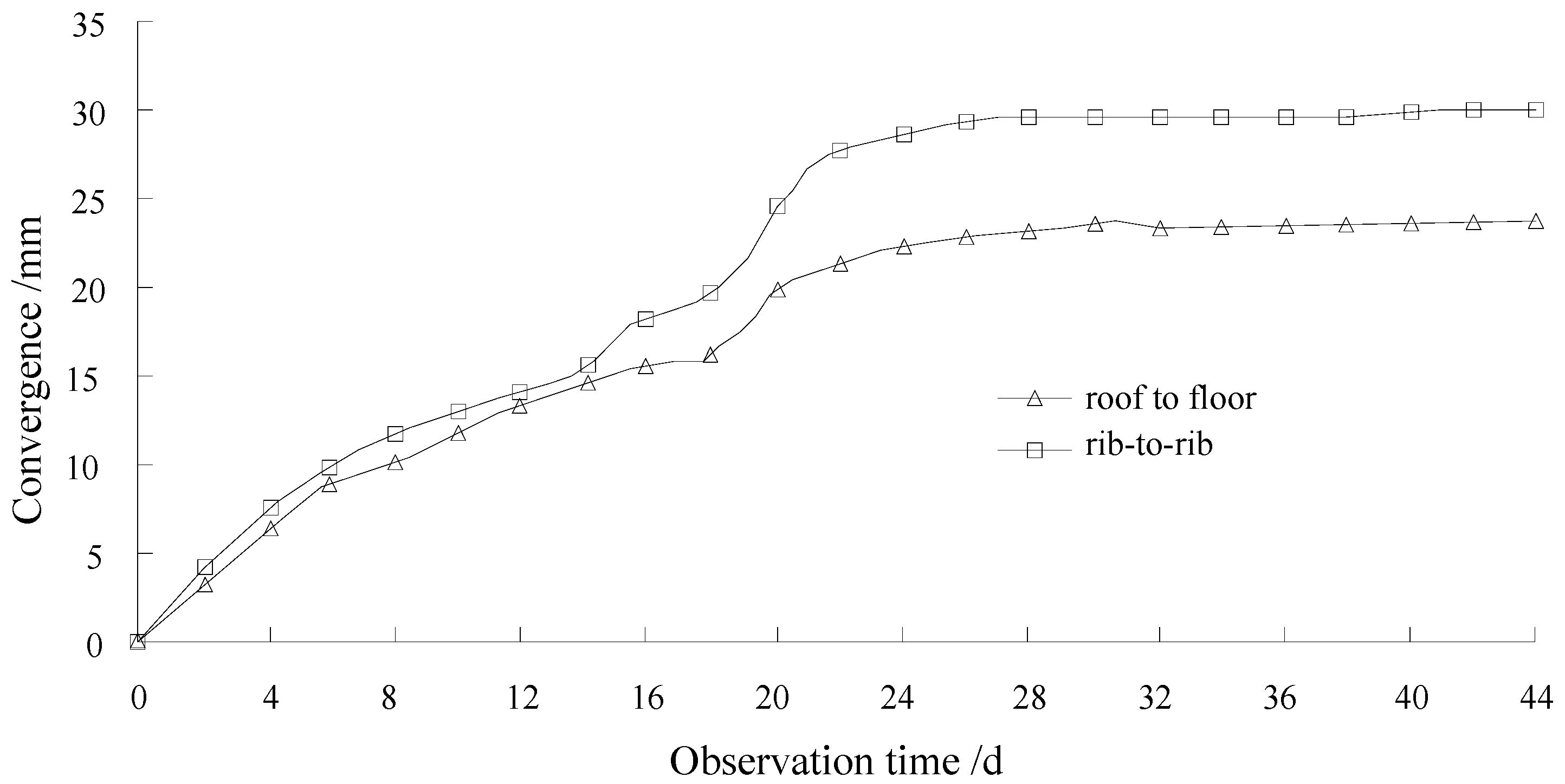
After the renovation of the chamber, the deformation of surrounding rock of chamber was observed and the observed deformation convergence of chamber is shown in Figure 17. It can be seen that the convergence speed of surrounding rock of chamber gradually diminishes and tends to zero after the renovation. This indicates that the surrounding rock of chamber is in a stable state, and that the deformation of surrounding rock was effectively controlled. This also suggests that the chamber bolt-grouting reinforcement and the pressure-relief slot construction design are reasonable and the field test is successful, and the construction ensures the normal use of the chamber.
6. Conclusions
This work conducted a systematic research for the anchoring-grouting and the floor pressure-relief supporting technology by using theoretical analysis, numerical calculation, and field industrial test in one coal mine in China. Some preliminary conclusions can be obtained.
- (1)
- The surrounding rock of the No.2 belt conveyor head chamber at Xinzhuang coal mine is weak in both lithology and rock strength, and the abutment pressure of the blind incline shaft protective pillar induces the concentrated stress of the surrounding rock of the chamber. Therefore, the effective load coefficient of the surrounding rock of chamber is higher, which is one of the main reasons of the chamber floor heave and the surrounding rock deformation failure.
- (2)
- Numerical results showed that after the floor pressure-relief slot was excavated in the head chamber, the vertical stress of floor surrounding rock of chamber and the horizontal stress of sides surrounding rock were significantly reduced when compared with the stress before the pressure-relief, and the floor vertical displacement basically remains unchanged. This demonstrates that the floor pressure-relief slot can effectively control the chamber floor heave and is in favor of the long-term stability of the surrounding rock of the chamber.
- (3)
- When the head chamber was repaired, the combined support with the bolt-mesh-shotcreting and anchor cable was applied firstly. Then, the chamber sides and roof shallow surrounding rock were grouted by grouting bolts, and the chamber sides and floor deep surrounding rock were grouted by grouting anchor cable bundles. The chamber floor pressure-relief slot was excavated at last. After the implementation of the above integrated techniques, the surrounding rock of chamber was in a stable state, which suggested that the field test is successful. Therefore, it is reasonable to design and carry out the bolt grouting support and the floor pressure-relief slot of the chamber.
- (4)
- The combined supporting technology with bolt-grouting and floor pressure-relief effectively controls the surrounding rock stability of the deep head chamber at Xinzhuang coal mine. This technology can provide technical support for the deep roadway supporting under similar conditions. It has practical significance and reference value on the development of surrounding rock control theory and technology in the deep roadways.
Acknowledgments
The authors wish to thank the National Natural Science Foundation of China (project No.51574110) for the financial support of this study.
Author Contributions
Xinxian Zhai conceived and designed the technical parameters; Guangshuai Huang analyzed the data; Chengyu Chen and Rubo Li established the observation station; Xinxian Zhai and Guangshuai Huang wrote the paper.
Conflicts of Interest
The authors declare no conflict of interest.
References
- Kovári, K. History of the sprayed concrete lining method—Part I: Milestones up to the 1960s. Tunn. Undergr. Space Technol. 2003, 18, 57–69. [Google Scholar] [CrossRef]
- Kovári, K. History of the sprayed concrete lining method—Part II: Milestones up to the 1960s. Tunn. Undergr. Space Technol. 2003, 18, 71–83. [Google Scholar] [CrossRef]
- Indraratna, B. Effect of bolts on failure modes near tunnel openings in soft rock. Geotechnique 1993, 43, 433–442. [Google Scholar] [CrossRef]
- Bobet, A.; Einstein, H.H. Tunnel reinforcement with rock bolts. Tunn. Undergr. Space Technol. 2011, 26, 100–123. [Google Scholar] [CrossRef]
- Kang, H.; Wu, Y.; Gao, F.; Lin, J.; Jiang, P. Fracture characteristics in rock bolts in underground coal mine roadways. Int. J. Rock Mech. Min. Sci. 2013, 62, 105–112. [Google Scholar] [CrossRef]
- Ju, W.J. Development and prospect of anchored-bolt supporting technology in Chinese coal mines. Coal Min. Technol. 2014, 19, 1–6. [Google Scholar] [CrossRef]
- Kang, H.P.; Wang, J.H.; Lin, J. Case studies of rock bolting in coal mine roadways. Chin. J. Rock Mech. Eng. 2010, 29, 649–664. [Google Scholar]
- Guo, D.M.; Wang, C.G.; Wu, Y.Y. Surrounding rock failure mechanism and technology of grouting reinforcement in winch chamber. Coal Sci. Technol. 2014, 42, 27–30. [Google Scholar] [CrossRef]
- Vižintin, G.; Mayer, J.; Lajlar, B.; Vukelič, Ž. Rock burst dependency on the type of steel arch support in the Velenje mine. Mater. Tehnol. 2017, 51, 11–18. [Google Scholar] [CrossRef]
- Vižintin, G.; Kocjančič, M.; Vulić, M. Study of coal burst source locations in the Velenje colliery. Energies 2016, 9, 507. [Google Scholar] [CrossRef]
- Vukelič, Ž.; Dervarič, E.; Šporin, J.; Vižintin, G. The development of dewatering predictions of the Velenje coal mine. Energies 2016, 9, 702. [Google Scholar] [CrossRef]
- Cai, Y.L.; Liu, C. Bolt and grouting combined reinforced support technology of large chamber in deep mine. Coal Sci. Technol. 2012, 40, 30–34. [Google Scholar] [CrossRef]
- Meng, Q.B.; Han, L.J.; Qiao, W.G. The deformation failure mechanism and control techniques of soft rock in deep roadways in Zhaolou mine. J. Min. Saf. Eng. 2013, 30, 165–172. [Google Scholar]
- Gao, M.S.; Zhang, N.; Guo, C.S.; Dou, L.M. Mechanics and practice of combined supporting technology of 3D anchor-cable and unloading technology of wall of roadway. Chin. J. Geotech. Eng. 2005, 27, 587–590. [Google Scholar]
- Zhang, X.Y. Deformation Mechanism and Pressure Relief of Surrounding Rock of Main Roadway under Dynamic Pressure. Master’s Thesis, Anhui University of Science and Technology, Huainan, China, 2007. [Google Scholar]
- LI, C.C. Field observations of rock bolts in high stress rock masses. Rock Mech. Rock Eng. 2010, 43, 491–496. [Google Scholar] [CrossRef]
- Shen, J. Pressure-relief and support technology of large-section chamber in soft rock. Coal Eng. 2011, 58, 67–68. [Google Scholar]
- Yang, Q.S.; Gao, M.S.; Liu, B.T. Study and practices on floor heave prevention and control mechanism with pressure releasing slot in floor of mine high stressed roadway. Coal Eng. 2011, 58, 69–71. [Google Scholar]
- Chen, H.; Liu, A.; Wu, Y. Pressure relief supporting technology for full section deep soft rock roadway with large deformation. Saf. Coal Mines 2015, 46, 136–138. [Google Scholar] [CrossRef]
- Zhai, X.X.; Yang, X.L.; Zeng, X.T. Relationship between deformation failure of blind incline shafts and their safety pillars. Min. Metall. Eng. 2003, 23, 20–22. [Google Scholar]
- Du, J.P.; Jiang, X.Y.; Qian, M.G. The application of effective load coefficient to the deep mining in Suncun colliery. Chin. J. Rock Mech. Eng. 1994, 13, 365–373. [Google Scholar]
- Kang, H.P. Simulation and practice of roof pressure relief on soft chamber. Mine Constr. Technol. 1993, 14, 32–35. [Google Scholar]
- Wang, X.F.; Gao, M.Z. Analysis on numerical simulation of pressure releasing slots in different location of mine high stress and soft rock roadway. Saf. Coal Mines 2013, 44, 76–79. [Google Scholar]
- Wang, X.F.; Zhang, D.S.; Chen, J.X. Numerical analysis on slotted reinforcement floor to control floor heave of soft rock chamber. Coal Eng. 2006, 53, 61–63. [Google Scholar]
- Yang, Z.B. Reasonable depth analysis of floor pressure-relief trough of large-section chamber in soft rock. Min. Saf. Environ. Prot. 2011, 38, 46–48. [Google Scholar]
- Li, W.T.; Yang, N.; Li, T.C.; Zhang, Y.H.; Wang, G. A new approach to simulate the supporting arch in a tunnel based on improvement of the beam element in FLAC3D. J. Zhejiang Univ. Sci. A Appl. Phys. Eng. 2017, 18, 179–193. [Google Scholar] [CrossRef]
- Zhuo, X.D.; Cui, W. Numerical simulation on high-strength pre-stressing force support for roadway surrounding rock based on Flac3D. Saf. Coal Mines 2016, 47, 210–212. [Google Scholar] [CrossRef]
- Peng, S.S. Coal Mine Ground Control; China University of Mining and Technology Press: Xuzhou, China, 2013. [Google Scholar]
Figure 1.
Location of Xinzhuang coal mine.
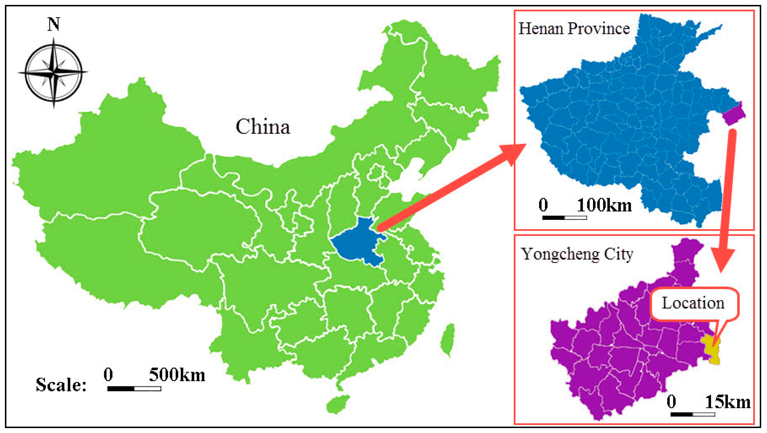
Figure 2.
Integrated histogram of surrounding rock of chamber.

Figure 3.
Layout of the chamber (a) Plane drawing (b) Sectional drawing.
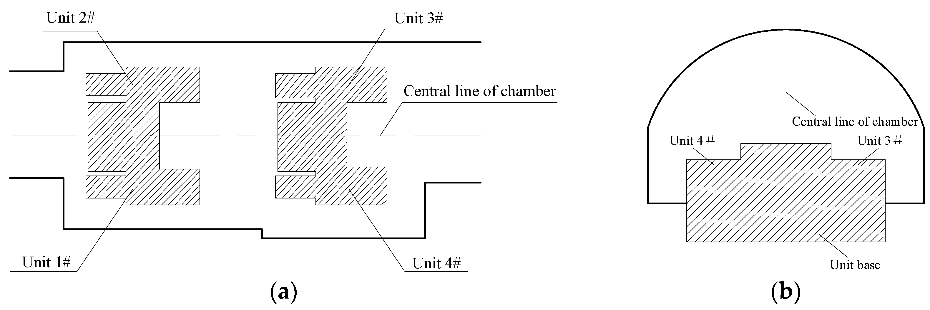
Figure 4.
Mechanical model for numerical calculation.
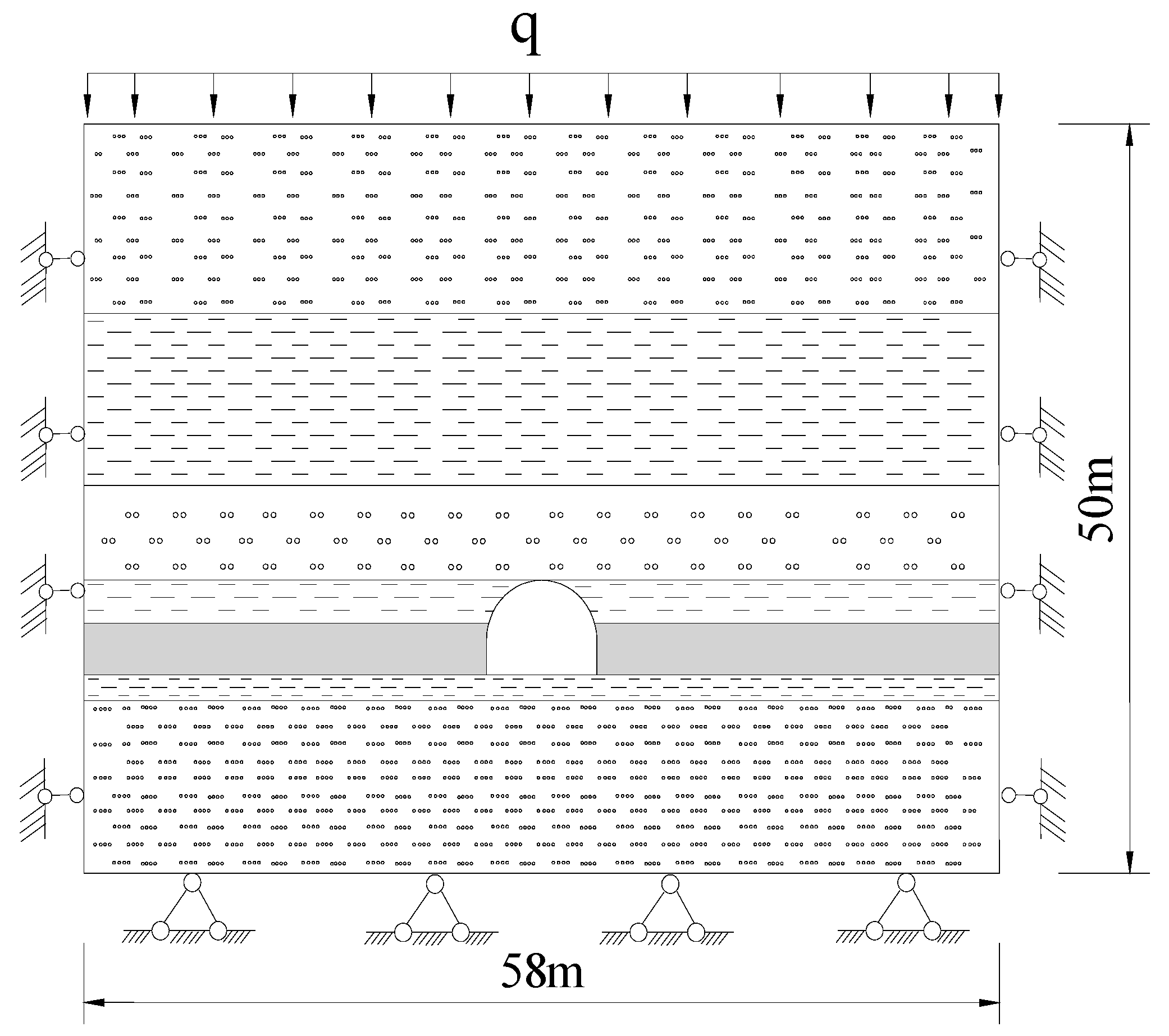
Figure 5.
Vertical stress field of the surrounding rock of chamber prior to pressure-relief.

Figure 6.
Vertical stress field of the surrounding rock of chamber after pressure-relief.

Figure 7.
Distribution curves of the vertical stress for roof and floor strata of the chamber prior to and after pressure-relief. (a) Distribution curves of the vertical stress for the floor; (b) Distribution curves of the vertical stress for the roof. Curve 1—prior to pressure-relief; Curve 2—after pressure-relief.

Figure 8.
Distribution curves of the vertical displacements for roof and floor strata of the chamber prior to and after pressure-relief. (a) Distribution curves of the vertical displacements for the floor; (b) Distribution curves of the vertical displacements for the roof. Curve 1—prior to pressure-relief; Curve 2—after pressure-relief.

Figure 9.
Horizontal stress field of surrounding rock of chamber prior to pressure-relief.
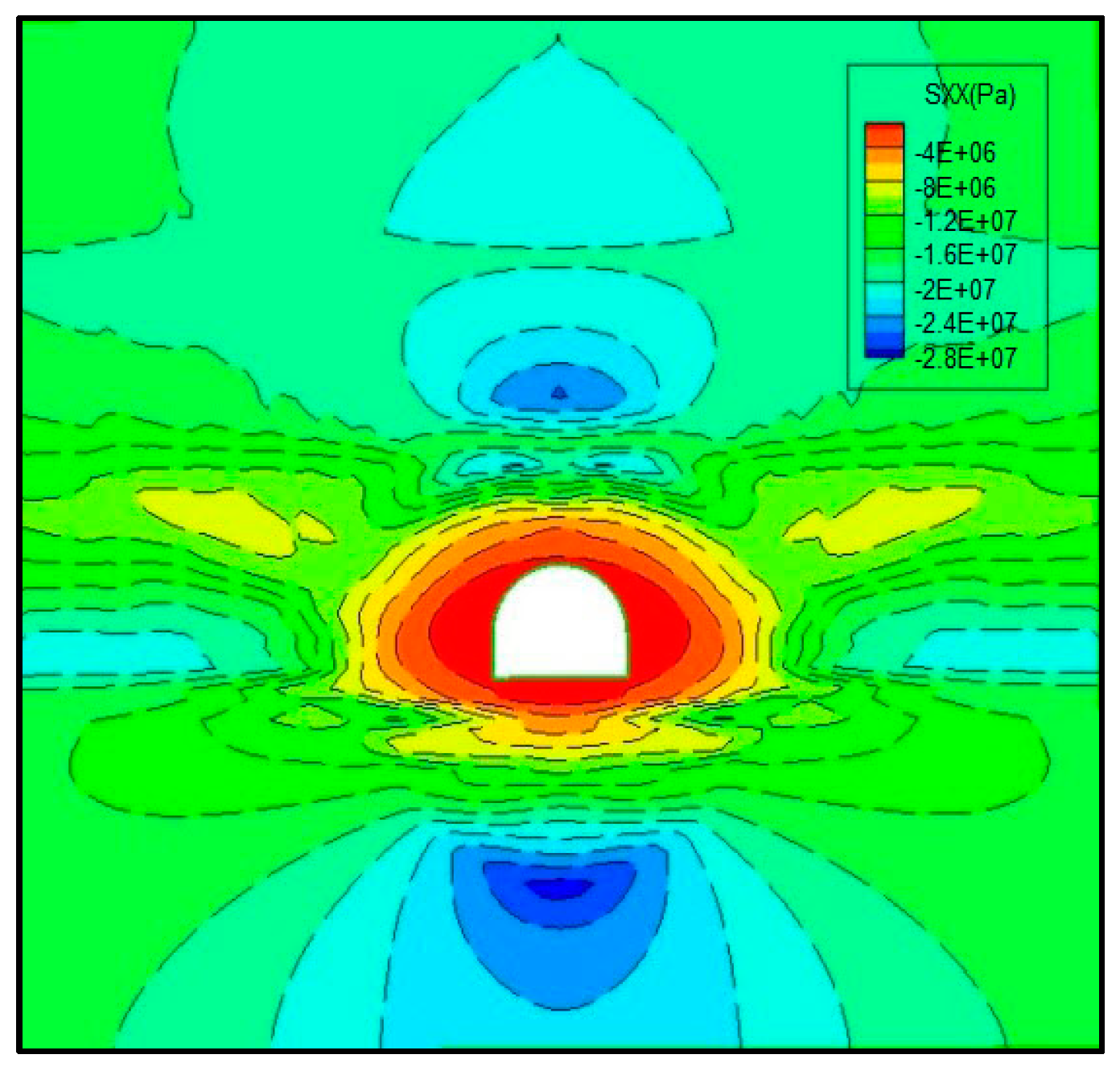
Figure 10.
Horizontal stress field of surrounding rock of chamber after pressure-relief.
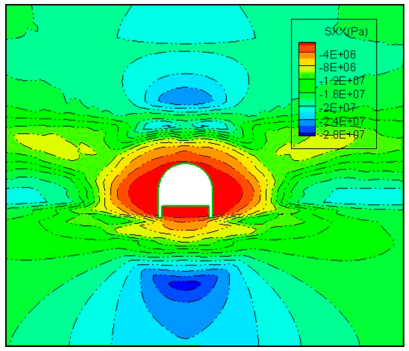
Figure 11.
Distribution curves of the horizontal stress on surrounding rock of chamber prior to and after pressure-relief: Curve 1—prior to pressure-relief; Curve 2—after pressure-relief.
Figure 11.
Distribution curves of the horizontal stress on surrounding rock of chamber prior to and after pressure-relief: Curve 1—prior to pressure-relief; Curve 2—after pressure-relief.

Figure 12.
Distribution curves of the horizontal displacements on surrounding rock of chamber prior to and after pressure-relief: Curve 1—prior to pressure-relief; Curve 2—after pressure-relief.
Figure 12.
Distribution curves of the horizontal displacements on surrounding rock of chamber prior to and after pressure-relief: Curve 1—prior to pressure-relief; Curve 2—after pressure-relief.
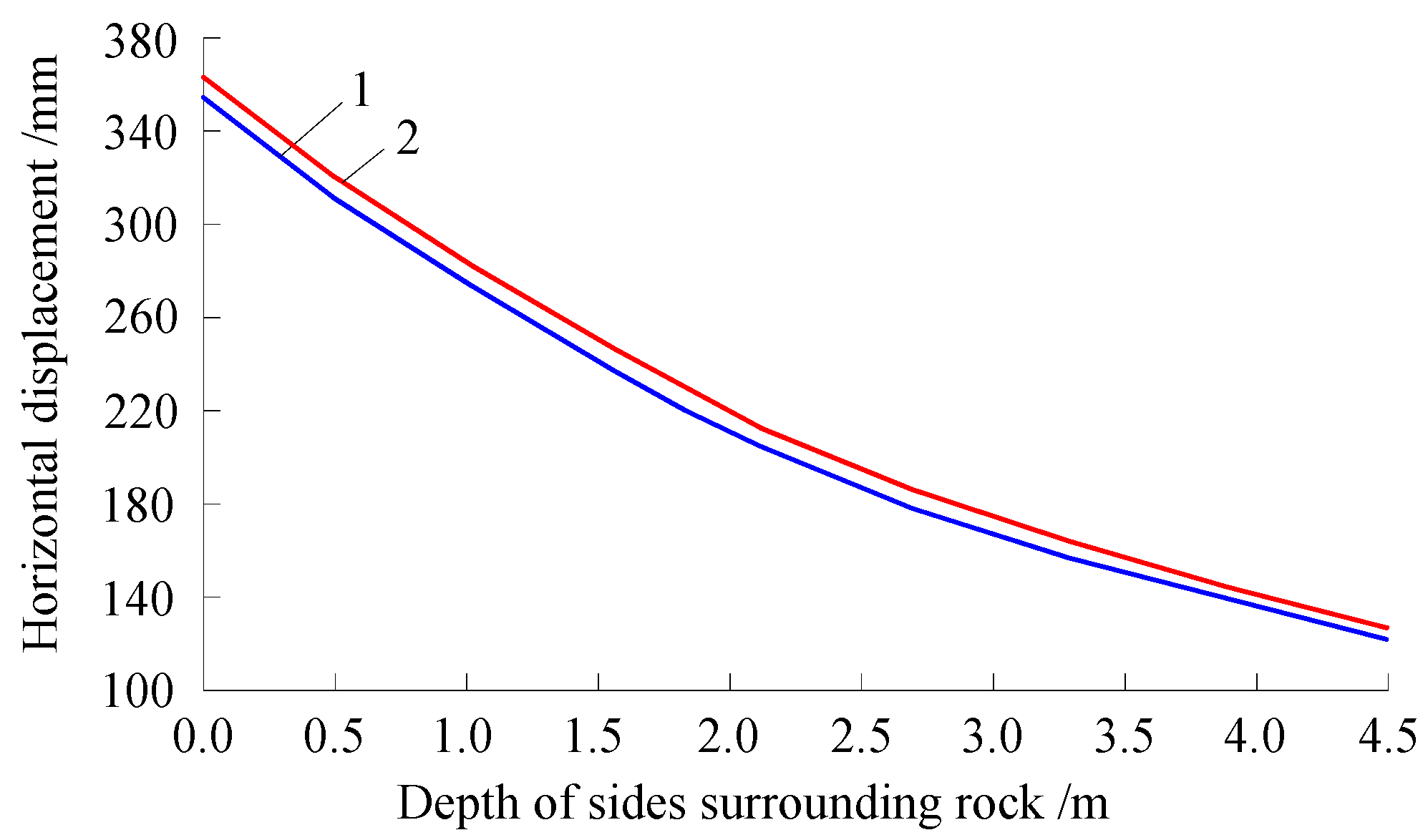
Figure 13.
Layout plane drawing of chamber with anchoring-grouting and floor relief supporting.

Figure 14.
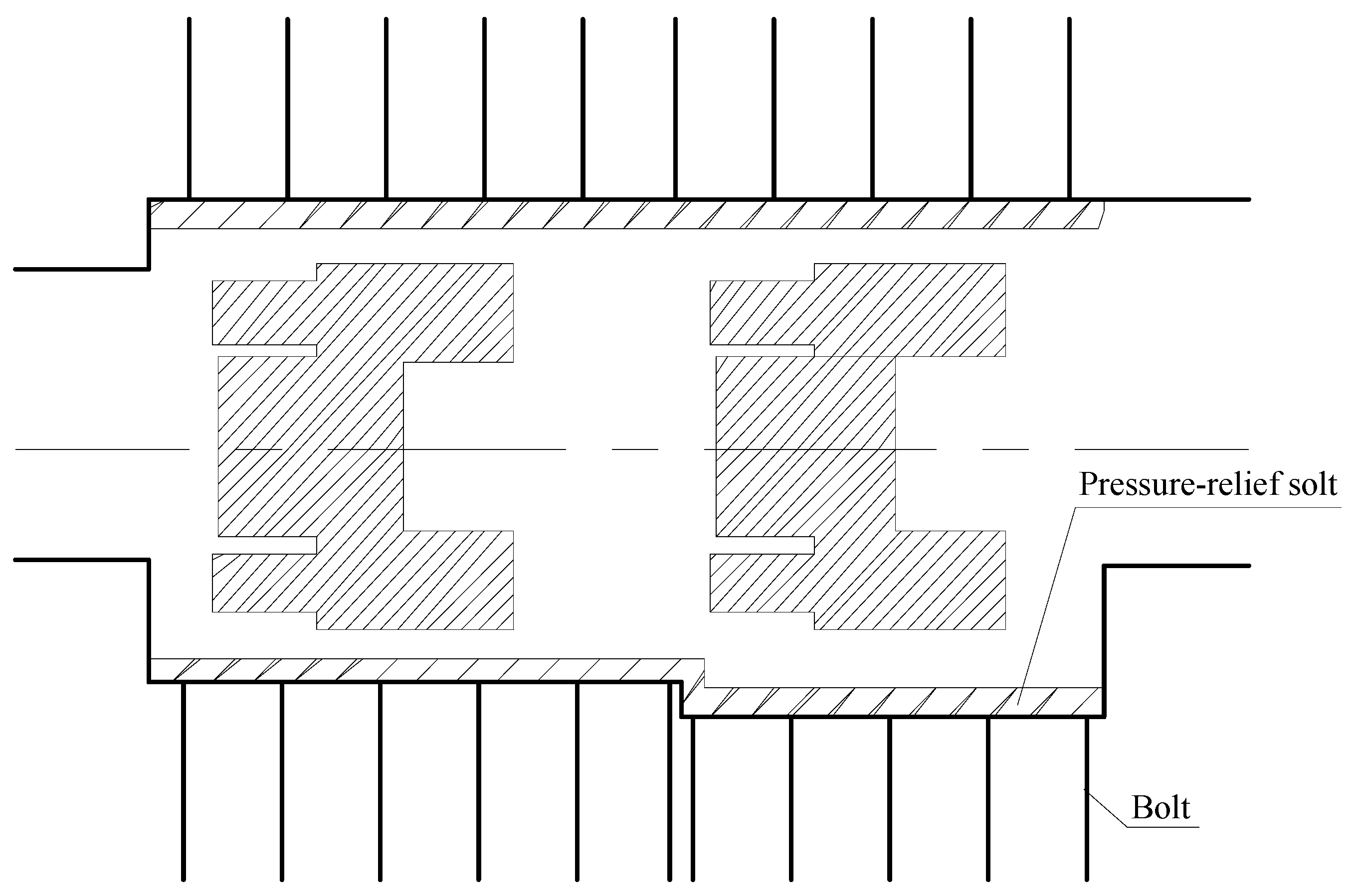
Sectional drawing of chamber with anchoring-grouting and floor relief supporting: the unit of the number is millimeter (mm).
Figure 14.
Sectional drawing of chamber with anchoring-grouting and floor relief supporting: the unit of the number is millimeter (mm).
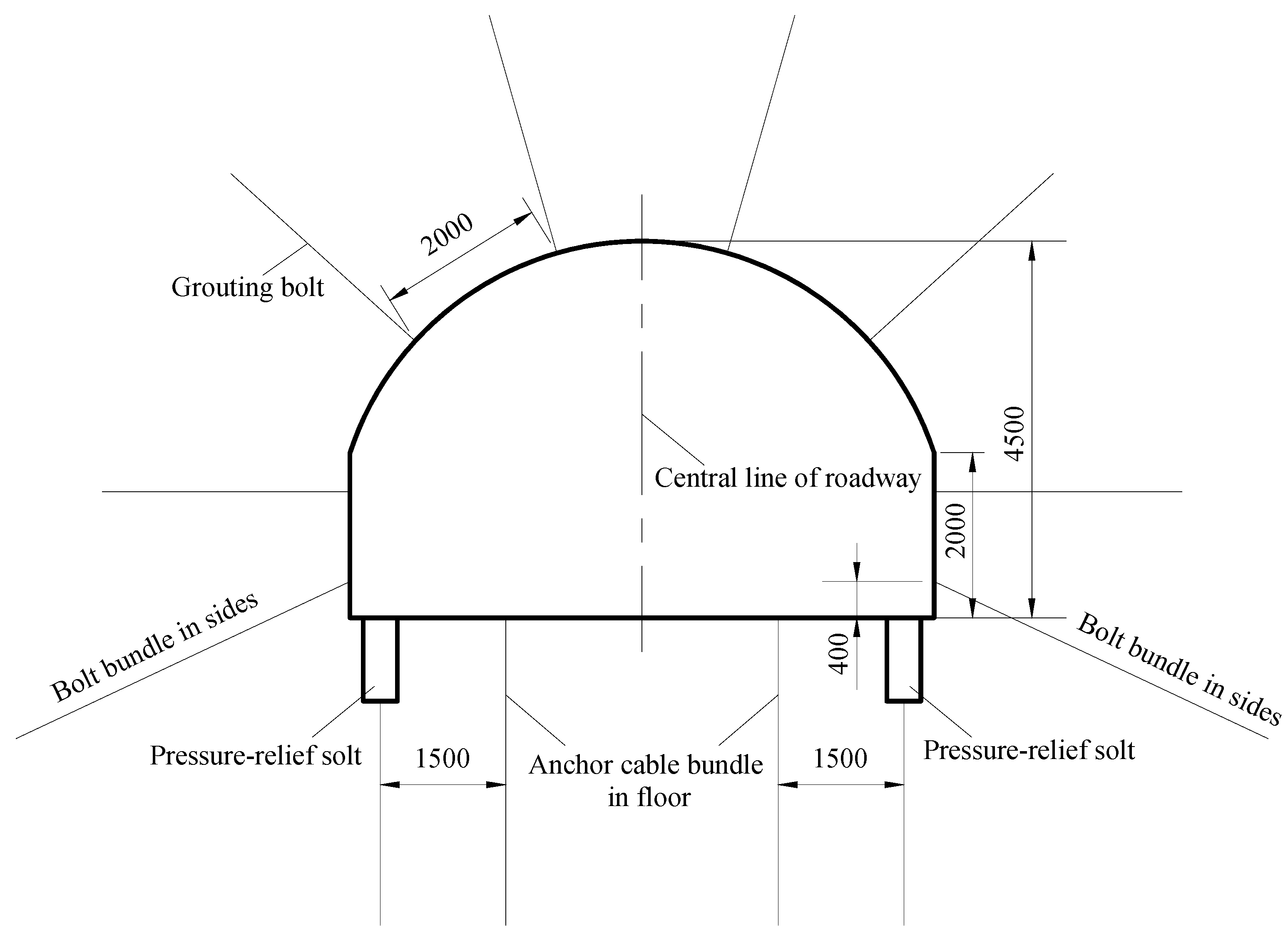
Figure 15.
Deformation and failure status of chamber. (a) Left side of chamber; (b) Chamber roof.
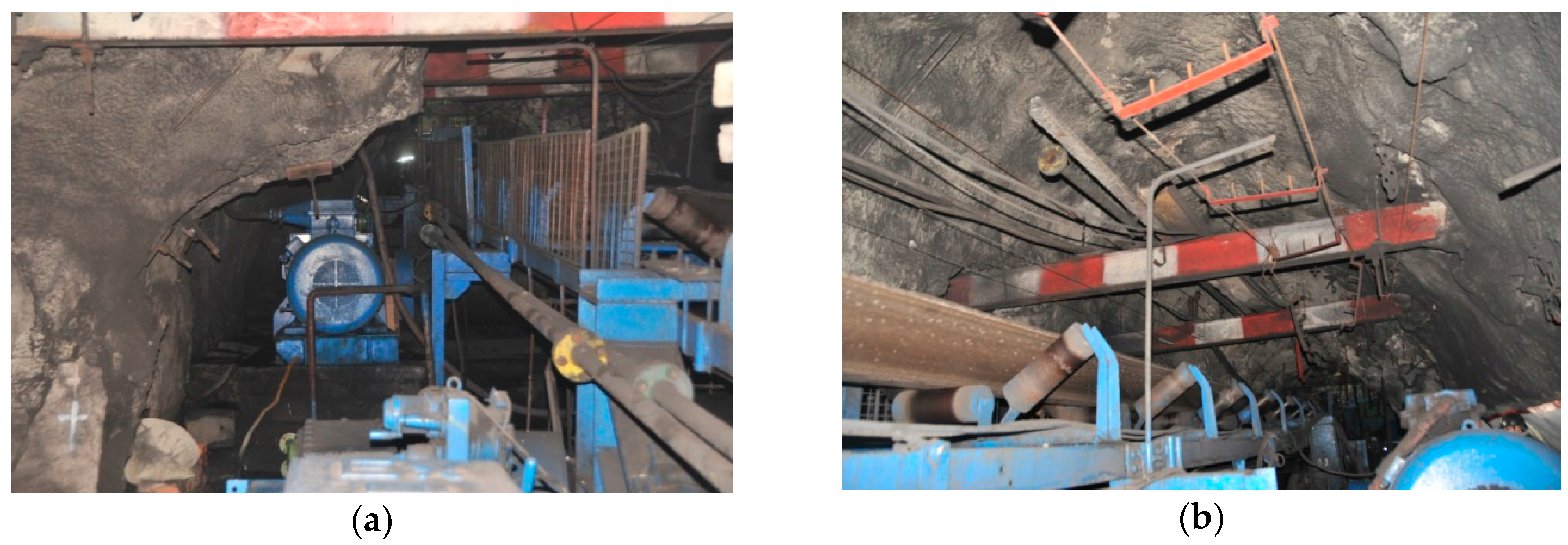
Figure 16.
Supporting status of renovated chamber. (a) Left side of chamber; (b) Chamber floor.

Figure 17.
The curves of surrounding rock deformation convergence of chamber after renovated.

Table 1.
Physical and mechanical parameters of the strata of chamber.
| Parameters | Thickness (m) | Bulk Modulus (GPa) | Shear Modulus (GPa) | Tensile Strength (MPa) | Cohesion (MPa) | Internal Friction Angle (°) | |
|---|---|---|---|---|---|---|---|
| Lithology | |||||||
| Fine-grained sandstone | 11.0 | 14.00 | 6.46 | 2.20 | 0.37 | 44.6 | |
| Sandy mudstone | 10.0 | 1.34 | 1.09 | 0.82 | 0.28 | 29.2 | |
| Medium-grained sandstone | 5.5 | 5.31 | 3.50 | 1.40 | 0.31 | 39.8 | |
| Sandy mudstone | 2.5 | 1.34 | 1.09 | 0.82 | 0.28 | 29.2 | |
| Coal seam II-2 | 3.0 | 0.57 | 0.26 | 0.08 | 0.40 | 30.5 | |
| Sandy mudstone | 1.5 | 1.34 | 1.09 | 0.82 | 0.28 | 29.2 | |
| Siltstone | 16.5 | 1.70 | 1.50 | 2.10 | 1.20 | 30.0 | |
© 2018 by the authors. Licensee MDPI, Basel, Switzerland. This article is an open access article distributed under the terms and conditions of the Creative Commons Attribution (CC BY) license (http://creativecommons.org/licenses/by/4.0/).
Share and Cite
MDPI and ACS Style
Zhai, X.; Huang, G.; Chen, C.; Li, R. Combined Supporting Technology with Bolt-Grouting and Floor Pressure-Relief for Deep Chamber: An Underground Coal Mine Case Study. Energies 2018, 11, 67. https://doi.org/10.3390/en11010067
AMA Style
Zhai X, Huang G, Chen C, Li R. Combined Supporting Technology with Bolt-Grouting and Floor Pressure-Relief for Deep Chamber: An Underground Coal Mine Case Study. Energies. 2018; 11(1):67. https://doi.org/10.3390/en11010067
Chicago/Turabian StyleZhai, Xinxian, Guangshuai Huang, Chengyu Chen, and Rubo Li. 2018. "Combined Supporting Technology with Bolt-Grouting and Floor Pressure-Relief for Deep Chamber: An Underground Coal Mine Case Study" Energies 11, no. 1: 67. https://doi.org/10.3390/en11010067
Note that from the first issue of 2016, this journal uses article numbers instead of page numbers. See further details here.