Article

Robust Tracking Controller for a DC/DC Buck-Boost Converter–Inverter–DC Motor System

by
Eduardo Hernández-Márquez
1,2,*,
Carlos Alejandro Avila-Rea
1,
José Rafael García-Sánchez
3,
Ramón Silva-Ortigoza
1,*,
Gilberto Silva-Ortigoza
4,
Hind Taud
1 and
Mariana Marcelino-Aranda
5
1
Área de Mecatrónica, Centro de Innovación y Desarrollo Tecnológico en Cómputo, Instituto Politécnico Nacional, Ciudad de Mexico 07700, Mexico
2
Departamento de Mecatrónica, Instituto Tecnológico Superior de Poza Rica, Veracruz 93230, Mexico
3
Departamento de Procesos Productivos, Unidad Lerma, Universidad Autónoma Metropolitana, Estado de Mexico 52005, Mexico
4
Facultad de Ciencias Físico Matemáticas, Benemérita Universidad Autónoma de Puebla, Puebla 72000, Mexico
5
Sección de Estudios de Posgrado e Investigación, Unidad Profesional Interdisciplinaria de Ingeniería y Ciencias Sociales y Administrativas, Instituto Politécnico Nacional, Ciudad de México 08400, Mexico
*
Authors to whom correspondence should be addressed.
Energies 2018, 11(10), 2500; https://doi.org/10.3390/en11102500
Submission received: 24 August 2018 / Revised: 15 September 2018 / Accepted: 18 September 2018 / Published: 20 September 2018
(This article belongs to the Special Issue Power Electronics 2018)

Abstract

:
This paper has two aims. The first is to develop a robust hierarchical tracking controller for the DC/DC Buck-Boost–inverter–DC motor system. This controller considers a high level control for the inverter–DC motor subsystems and a low level control for the DC/DC Buck-Boost converter subsystem. Such controls solve the tracking task associated with the angular velocity of the motor shaft and the output voltage of the converter, respectively, via the differential flatness approach. The second aim is to present a comparison of the robust hierarchical controller to a passive controller. This, with the purpose of showing that performance achieved with the hierarchical controller proposed in this paper, is better than the one achieved with the passive controller. Both controllers are experimentally implemented on a prototype of the DC/DC Buck-Boost–inverter–DC motor system by using Matlab-Simulink along with the DS1104 board from dSPACE. According to experimental results, the proposal in the present paper achieves a better performance than the passive controller.

Graphical Abstract

1. Introduction

According to literature, several applications have benefited using DC/DC power electronic converters as drivers for DC motors [1,2,3,4,5,6,7]. Particularly, mechanical systems [1], robots [2,3,4], electric vehicles [5], and renewable energy [6,7]. Thereby, the design of controls for DC motors driven by DC/DC power converters is a current research topic. On the one hand, important works dealing with DC/DC converters-DC motor systems are: Buck–motor [8,9,10,11,12,13,14,15,16,17,18], Boost–motor [19,20,21], Buck-Boost–motor [22,23], Sepic–motor and Cuk–motor [24]. In [8,9,10,11,12,13,14,15,16,17,18,19,20,21,22,23,24] the unidirectional drive of the motor shaft was solved. This was accomplished due to the operation principle of the DC/DC converters since they only deliver unipolar voltages. On the other hand, DC/DC converters have been used to generate bipolar voltages with the aim of bidirectionally driving DC motors [6,25,26,27,28,29,30,31]; leading to the DC/DC converter–inverter–DC motor systems which are the subject of this paper. In this direction, the modeling and experimental validation of the DC/DC Buck–inverter–DC motor system was reported in [25] by Silva-Ortigoza et al. For the same system, a passivity-based tracking control and robust tracking controls were proposed by Silva-Ortigoza et al. in [26] and Hernández-Márquez et al. in [27], respectively. García-Rodríguez et al. in [28] and Silva-Ortigoza et al. in [29] developed the mathematical model and a passive tracking control for the DC/DC Boost converter–inverter–DC motor system. Moreover, for the DC/DC Buck-Boost converter–inverter–DC motor system, Hernández-Márquez et al. carried-out the modeling and experimental validation in [30] and designed a passive tracking control in [31]. Lastly, Linares-Flores et al. solved the regulation problem associated with the DC/DC Sepic converter–inverter–DC motor system via a passive control in [6]. It is worth noting that industrial and mechatronic applications would be limited if [8,9,10,11,12,13,14,15,16,17,18,19,20,21,22,23,24] were only considered compared with [6,25,26,27,28,29,30,31]. For example, in mobile robots [2,3,4], and underactuated mechanical systems [32,33], among others.
Having undertaken the literature review associated with DC motors driven by DC/DC converters, it was found that several controls have solved the angular velocity regulation and trajectory tracking tasks in two fashions: (i) unidirectional [8,9,10,11,12,13,14,15,16,17,18,19,20,21,22,23,24] and (ii) bidirectional [6,26,27,29,31]. Motivated by the ideas previously mentioned, the hierarchical control approach in mobile robotics (see [2,3,4,34]), and use of DC/DC converter-DC motor systems (see [11,12,13,27]), the purpose of the present paper is twofold. First, to introduce, for the first time, a robust hierarchical tracking controller for the DC/DC Buck-Boost converter–inverter–DC motor system. Secondly, to experimentally validate the proposed approach and compare to results associated with the passive controller reported in [31]. The aim of this comparison is to show that performance achieved with the hierarchical controller is better than the one achieved with the passive controller.
The remainder of this paper is as follows. In Section 2 the DC/DC Buck-Boost converter–inverter– DC motor system is presented. In Section 3 the robust tracking controller is developed. In order to verify the performance of such a controller, in Section 4 experimental results are shown. Finally, concluding remarks are given in Section 5.

2. DC/DC Buck-Boost Converter–Inverter–DC Motor System

This section presents the DC/DC Buck-Boost converter–inverter–DC motor system and its corresponding mathematical model.
The electronic diagram of the system under study is shown in Figure 1. As can be observed, such a system is composed of three subsystems: Buck-Boost converter, inverter, and DC motor. The DC/DC Buck-Boost converter steps-down or steps-up the input voltage to the DC motor. This converter is composed of a power supply E, a transistor Q 1 and a diode D that regulate the output voltage υ in capacitor C and load R, and an inductor L where the current i flows through. The inverter aims to drive the bidirectional rotation of the motor shaft. It is composed of four transistors which are labeled as Q 2 and Q ¯ 2 ; these devices operate complementary to each other. That is, if Q 2 is on, then Q ¯ 2 is off and vice versa. Regarding the DC motor, parameters R a and L a are the armature resistance and armature inductance. While i a and ω are the armature current and angular velocity of the motor shaft. Additionally, for the DC motor, the parameters J, b, k e , and k m are considered, which correspond to the moment of inertia of the rotor and load, the viscous friction coefficient, the counterelectromotive force constant, and the torque constant, respectively.
The average model of the DC/DC Buck-Boost–inverter–DC motor system, according to [30], is given by
L d i d t = E u 1 a v + ( 1 u 1 a v ) υ ,
C d υ d t = ( 1 u 1 a v ) i υ R i a u 2 a v ,
L a d i a d t = υ u 2 a v R a i a k e ω ,
J d ω d t = k m i a b ω ,
with u 1 a v [ 0 , 1 ) and u 2 a v [ 1 , 1 ] the duty cycles of the Buck-Boost converter and inverter, respectively, whereas the remainder of the parameters were previously defined.

3. Hierarchical Controller

By considering the hierarchical controller approach, similar to the one used in mobile robotics [2,3,4,34] and DC/DC converter-DC motor systems [11,12,13,27]. In this section, a hierarchical controller that solves the bidirectional angular velocity tracking task for the DC/DC Buck-Boost–inverter–DC motor system is designed. This controller has the following structure:
  • High level control. This is a differential flatness-based control, u 2 a v , and is related to the inverter–DC motor subsystems. This control ensures the required voltage ϑ so that the bidirectional angular velocity trajectory tracking task can be achieved, i.e., ω ω * .
  • Low level control. In order to solve the voltage tracking on the Buck-Boost converter subsystem, i.e., υ υ * , an alternative model of the converter is used along with the differential flatness approach to generate the control u 1 a v .
  • Integration of controls. The controls designed in items A and B are interconnected through an inner control-loop, giving rise to the hierarchical controller.

3.1. High Level Control

Assuming, from the very beginning, that the DC/DC Buck-Boost converter and the inverter–DC motor subsystems operate independently, then, from Equations (3) and (4), the mathematical model associated with the inverter–DC motor is,
L a d i a d t = ϑ R a i a k e ω ,
J d ω d t = k m i a b ω ,
with ϑ being the motor armature voltage, defined by
ϑ = υ u 2 a v .
According to [12,35], the flat-output of Equations (5) and (6) is F 2 = ω . Therefore, the model of the inverter–DC motor subsystems is rewritten in terms of such an output as,
ϑ = J L a k m F ¨ 2 + 1 k m b L a + J R a F ˙ 2 + b R a k m + k e F 2 .
From Equation (8), a control strategy that allows F 2 F 2 * , with F 2 * being the desired angular velocity, is:
ϑ = J L a k m μ + 1 k m b L a + J R a F ˙ 2 + b R a k m + k e F 2 .
If Equation (9) is introduced in Equation (8), then the tracking problem related to the angular velocity of this subsystem is reduced to control the following:
F ¨ 2 = μ
where μ is an auxiliary control defined by
μ = F ¨ 2 * δ 2 F ˙ 2 F ˙ 2 * δ 1 F 2 F 2 * δ 0 0 t F 2 F 2 * d τ ,
with δ 2 , δ 1 , and δ 0 being the control gains. Once Equation (11) is replaced in Equation (10), the tracking error is defined as e 2 = F 2 F 2 * , and the derivative with respect to time of the resulting expression is calculated. Then, the tracking error dynamics is obtained:
e 2 + δ 2 e ¨ 2 + δ 1 e ˙ 2 + δ 0 e 2 = 0
whose characteristic polynomial in closed-loop is
p 2 s = s 3 + δ 2 s 2 + δ 1 s + δ 0 .
By equating Equation (13) with the following Hurwitz polynomial:
p 2 d s = s + a 2 s 2 + 2 ξ 2 ω n 2 s + ω n 2 2
with a 2 > 0 , ξ 2 > 0 , and ω n 2 > 0 . Hence, the gains δ 2 , δ 1 , and δ 0 are determined by
δ 2 = a 2 + 2 ξ 2 ω n 2 , δ 1 = 2 ξ 2 ω n 2 a 2 + ω n 2 2 , δ 0 = a 2 ω n 2 2 ,
thus, it is assured that F 2 F 2 * .

3.2. Low Level Control

Considering that, it does not exist an interconnection between the Buck-Boost converter and the inverter–DC motor, that is i a = 0 ; from Equations (1) and (2) the following model is obtained:
L d i d t = E u 1 a v + ( 1 u 1 a v ) υ ,
C d υ d t = ( 1 u 1 a v ) i υ R .
Since a direct control strategy for the voltage υ leads to a non-minimum phase system, i.e., an infeasible system [36,37]. In this paper, the first alternative model of the converter reported in [38] is used, instead of Equations (16) and (17),
d υ d t = R E E u 1 a v + ( 1 u 1 a v ) υ L 2 υ E ,
where i is defined by
i = υ υ E R E .
By expressing Equation (18) in terms of F 1 = υ ,
u 1 a v = 1 E R ( E F 1 ) L ( 2 F 1 E ) F ˙ 1 E R F 1
and based on differential flatness theory [35]. A suitable definition for u 1 a v to achieve the control objective is,
u 1 a v = 1 E R ( E F 1 ) L ( 2 F 1 E ) η E R F 1 .
After replacing Equation (21) in Equation (20), the tracking problem related to the voltage of the converter is reduced to control the following:
F ˙ 1 = η ,
where η is an auxiliary control. With the aim of ensuring that F 1 F 1 * , with F 1 * being the desired voltage, a convenient selection for η is
η = F ˙ 1 * β 1 F 1 F 1 * β 0 0 t F 1 F 1 * d τ ,
being β 1 , β 0 positive constants. Once Equation (23) is replaced in Equation (22), the tracking error is defined as e 1 = F 1 F 1 * , and the derivative with respect to time of the resulting expression is calculated. Then, the tracking error dynamics is obtained,
e ¨ 1 + β 1 e ˙ 1 + β 0 e 1 = 0
whose characteristic polynomial is
p 1 s = s 2 + β 1 s + β 0 .
After equating Equation (25) with the following Hurwitz polynomial:
p 1 d s = s 2 + 2 ξ 1 ω n 1 s + ω n 1 2 ,
it is found that the gains β 1 and β 0 are given by
β 1 = 2 ξ 1 ω n 1 , β 0 = ω n 1 2 ,
which guarantees that F 1 F 1 * as long as ξ 1 , ω n 1 > 0 .

3.3. Integration of Controls

In order to solve the bidirectional angular velocity trajectory tracking task for the DC/DC Buck-Boost converter–inverter–DC motor system, a hierarchical controller is designed in this subsection.
By considering the mathematical model Equations (5) and (6), it was found that a control ensuring ω ω * is given by Equation (9); that is,
ϑ = J L a k m μ + 1 k m b L a + J R a ω ˙ + b R a k m + k e ω ,
where μ is determined by Equation (11). On the other hand, ϑ was defined in Equation (7) as
ϑ = υ u 2 a v
and considers the voltage υ as the power supply of the inverter–DC motor subsystems. Thus, the control associated for these subsystems is found to be
u 2 a v = ϑ υ .
Furthermore, since the inverter–DC motor is fed by a Buck-Boost converter, a control achieving υ υ * is given by Equation (21); that is,
u 1 a v = 1 E R ( E υ ) L ( 2 υ E ) η E R υ ,
where η is determined by Equation (23). Therefore, the hierarchical controller, resulting from the interconnection of controls Equations (30) and (31), executes the trajectory tracking of both the voltage and the bidirectional angular velocity of the system.

4. Experimental Results

With the aim of highlighting the contribution of this research, the hierarchical controller previously designed is experimentally compared with the passive controller recently reported in [31]. The experimental implementation of both controllers is carried-out on a built prototype of the DC/DC Buck-Boost converter–inverter–DC motor system. Thus, this section presents the experimental results associated with both controllers. That is:
  • Hierarchical controller (designed in Section 3):
    u 1 a v = 1 E R ( E υ ) L ( 2 υ E ) η E R υ ,
    u 2 a v = 1 υ J L a k m μ + 1 k m b L a + J R a ω ˙ + b R a k m + k e ω ,
    with
    η = υ ˙ * β 1 υ υ * β 0 0 t υ υ * d τ , μ = ω ¨ * δ 2 ω ˙ ω ˙ * δ 1 ω ω * δ 0 0 t ω ω * d τ ,
    where the gains β 1 , β 0 and δ 2 , δ 1 , δ 0 are given, respectively, by
    β 1 = 2 ξ 1 ω n 1 , β 0 = ω n 1 2 ,
    δ 2 = a 2 + 2 ξ 2 ω n 2 , δ 1 = 2 ξ 2 ω n 2 a 2 + ω n 2 2 , δ 0 = a 2 ω n 2 2 .
  • Passive controller (recently reported in [31]):
    u 1 a v = u 1 a v * γ 1 ( υ * E ) i i * + α E υ υ * ,
    u 2 a v = u 2 a v * γ 2 b ω * k m υ υ * + υ * i a i a * ,
    with
    i * = υ * E E υ * R + J ω ˙ * + b ω * k m υ * L a J k m ω ¨ * + L a b + R a J k m ω ˙ * + R a b k m + k m ω * ,
    i a * = 1 k m J ω ˙ * + b ω * ,
    u 1 a v * = 1 E υ * L d i * d t υ * ,
    u 2 a v * = L a J k m ω ¨ * υ * + L a b + R a J k m ω ˙ * υ * + R a b k m + k m ω * υ * ,
    and γ 1 , γ 2 > 0 with α defined as,
    α = υ * E E R a b k m + k m b ω * 2 k m υ * + υ * R .

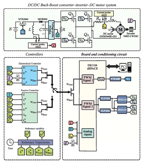
4.1. Experimental Testbed

The prototype used for implementing the hierarchical controller and the passive controller is described in this subsection. With the aim of a fair comparison the prototype reported in [31], associated with the passive controller, has been used in this paper. In this way, the experimental results are obtained by using the diagram of the system in closed-loop shown in Figure 2.
In Figure 2, connections of the experimental testbed to the DS1104 board and Matlab-Simulink are illustrated. The blocks composing such a figure are described below:
  • DC/DC Buck-Boost converter–inverter–DC motor system. This block corresponds to the built prototype of the system under study. Regarding the DC/DC Buck-Boost converter, according to [31], the following parameters are considered:
    L = 4.94 mH , C = 114.4 μ F , R = 64 Ω , E = 24 V .
    Whereas, four IRF640 transistors and two circuit-drivers IR2113 were used for the inverter. Related to the DC motor, an ENGEL GNM5440E-G3.1 ( 24 V , 95 W ) is used whose parameters are:
    L a = 2.22 mH , k m = 120.1 × 10 3 N · m A , R a = 0.965 Ω , k e = 120.1 × 10 3 V · s rad , J = 118.2 × 10 3 kg · m 2 , b = 129.6 × 10 3 N · m · s rad .
  • Board and conditioning circuit. This block electrically isolates the DS1104 board from the power stage via the NTE3087 and TLP250 optocouplers. Also, this block drives the converter and inverter when generating, through PWM1 and PWM2, the switched inputs u 1 and u 2 , respectively.
  • Controllers. In this block, the synthesis and programming of the hierarchical controller Equations (32) and (33) and the passive controller Equations (36) and (37) is carried-out via Matlab-Simulink. The corresponding program is shown in Figure 3, where the following four stages are observed: (i) Signals acquisition, (ii) Reference variables, (iii) Hierarchical controller, and (iv) Passive controller.
(i) Signals acquisition: Acquires all the system measurements, i.e., υ , ω , i, and i a by using a P5200A differential voltage probe, two A622 current probes, and an Omron E6B2-CWZ6C incremental encoder, respectively. In this block, a signal conditioning (SC) is also performed in each signal.
(ii) Reference variables: Regarding the desired trajectories υ * and ω * , they were proposed for all the experiments as follows:
υ * = υ ¯ i t i + [ υ ¯ f ( t f ) υ ¯ i t i ] φ ( t , t i , t f ) ,
ω * = ω ¯ i t i + [ ω ¯ f ( t f ) ω ¯ i t i ] φ ( t , t i , t f ) ,
where φ ( t , t i , t f ) is defined by the following polynomial:
φ ( t , t i , t f ) = 0 for t t i , t t i t f t i 3 20 45 t t i t f t i + 36 t t i t f t i 2 10 t t i t f t i 3 for t ( t i , t f ) , 1 for t t f .
Considering the aforementioned, the desired trajectories υ * and ω * smoothly interpolate between the initial voltage and velocity, selected as:
υ ¯ i ( 4 s ) = 25 V , ω ¯ i ( 4 s ) = 10 rad s ,
and the final voltage and velocity, chosen as:
υ ¯ f ( 6 s ) = 30 V , ω ¯ f ( 6 s ) = 10 rad s ,
that is, [ t i , t f ] = [ 4 s , 6 s ] . Thus, after replacing υ * (Equation (42) ) and ω * (Equation (43)) in Equations (38)–(41), the rest of the reference variables, this is, i * , i a * , u 1 a v * , and u 2 a v * are obtained.
(iii) Hierarchical controller: Here, the implementation of controller Equations (32) and (33) is carried-out via Matlab-Simulink. Gains of this controller, i.e., β 1 , β 0 and δ 2 , δ 1 , δ 0 , given by Equations (34) and (35), were obtained by selecting its parameters as follows:
ξ 1 = 25 , ω n 1 = 100 , a 2 = 15 , ξ 2 = 4.8 , ω n 2 = 50 .
(iv) Passive controller: The controller Equations (36) and (37) is programmed in this block through Matlab-Simulink. Gains of this controller, i.e., γ 1 and γ 2 , were chosen as:
γ 1 = 0.0004 , γ 2 = 0.0002 .
Lastly, a photograph of the system in closed-loop is shown in Figure 4.

4.2. Experimental Results

With the intention of showing the contribution of this research, in this subsection, the experimental results of the hierarchical controller, proposed in this paper, and those of the passive controller recently published in [31] are presented. Both controllers are implemented on the built prototype of the DC/DC Buck-Boost converter–inverter–DC motor system shown in Figure 4.
The experimental results are reported as follows. On the one hand, in Figure 5 and Figure 6, the results associated with the hierarchical controller, that is, Equations (32) and (33), correspond to υ h , i h , u 1 a v h , ω h , i a h , and u 2 a v h . The results related to the passive controller, that is, Equations (36) and (37), are υ p , i p , u 1 a v p , ω p , i a p , and u 2 a v p . On the other hand, in Figure 7 and Figure 8, the results of the tracking errors associated with the hierarchical controller correspond to e υ h , e i h , e ω h , and e i a h . These errors have been defined as,
e υ h = υ * υ h , e i h = i * i h , e ω h = ω * ω h , e i a h = i a * i a h .
While the results of the tracking errors related to the passive controller are e υ p , e i p , e ω p , e i a p , and have been defined as,
e υ p = υ * υ p , e i p = i * i p , e ω p = ω * ω p , e i a p = i a * i a p .
The experimental implementation of the system in closed-loop takes into account abrupt variations in parameters R and E. Considering such variations in these parameters is extremely important in control design, since they are the most common changes in this type of systems.

4.2.1. Experiment 1

With the aim of assessing the performance of both hierarchical controller and passive controller, this experiment presents the behavior of the system when the following abrupt variation in R is considered:
R m = R 0 t < 7.5 s , 30 % R 7.5 t 10 s .
In Figure 5 the corresponding results, related to Equation (46), are depicted. Figure 7 shows the tracking errors related to system variables, i.e., υ , i, ω , and i a , for both controllers.
Two important aspects can be observed in Figure 5 and Figure 7: (1) in general, both controllers solve the trajectory tracking task; however, the hierarchical controller achieves a small tracking error; (2) related to robustness, when perturbation Equation (46) is considered the passive controller stops executing the tracking task, whereas the hierarchical controller solves it successfully. On the other hand, for both controllers, u 1 a v and u 2 a v never get saturated.

4.2.2. Experiment 2

In this experiment, the performance of both controllers is assessed when an abrupt variation in power supply E is introduced. For this objective, the following variation in E is proposed:
E m = E 0 t < 7.5 s , 50 % E 7.5 t 10 s .
The experimental results of both controllers, when perturbation Equation (47) is considered, are shown in Figure 6. Whereas the corresponding tracking errors are depicted in Figure 8. From the obtained results, even if abrupt variations appeared in power supply E, it is observed, again, that the hierarchical controller solves in a better way the tracking task of main variables, i.e., υ and ω . Meanwhile, the passive controller does not achieve the tracking task when the abrupt change appears in E.

5. Conclusions

By means of designing a robust controller, the tracking task associated with the DC/DC Buck-Boost converter–inverter–DC motor system has been solved. The practical implementation of such a controller was performed using Matlab-Simulink along with the DS1104 board on a built system prototype. The experimental results successfully demonstrate the effectiveness and robustness of the proposed controller.
In order to accomplish the aforementioned, and based on the hierarchical controller approach, two controls based on differential flatness were developed; one of them for the DC/DC Buck-Boost converter and the other for the inverter-DC motor subsystems. Then, the hierarchical controller was experimentally implemented on a built prototype of the system. With the aim of showing the good performance of the controller proposed in this paper, an experimental comparison was carried-out with the passive controller recently reported in [31]. After an assessment of the obtained results, when abrupt perturbations in R and E are considered, it is shown that the system performance with the hierarchical controller is better than the one achieved with the passive controller when the trajectory tracking task is solved.
Motivated by the obtained experimental results, related to the robustness of the proposed controller for the DC/DC Buck-Boost converter–inverter–DC motor system, applications in mobile robotics [2,3,4,34] and underactuated mechanical systems [32,33] are considered as future work.

Author Contributions

Conceptualization, E.H.-M. and R.S.-O.; Data curation, C.A.A.-R. and J.R.G.-S.; Funding acquisition, R.S.-O., G.S.-O., H.T. and M.M.-A.; Investigation, E.H-M, C.A.A.-R., J.R.G.-S., R.S.-O. and G.S.-O.; Methodology, G.S.-O. and H.T.; Project administration, M.M.-A.; Resources, R.S.-O.; Software, E.H.-M., C.A.A.-R. and J.R.G.-S.; Supervision, R.S.-O.; Validation, E.H.-M., C.A.A.-R. and J.R.G.-S.; Visualization, E.H.-M., C.A.A.-R., J.R.G.-S., G.S.-O., H.T. and M.M.-A.; Writing-original draft, E.H.-M., J.R.G.-S. and R.S.-O.; Writing-review & editing, E.H.-M., C.A.A.-R., J.R.G.-S., R.S.-O., G.S.-O., H.T. and M.M.-A.

Funding

This research was funded by the Secretaría de Investigación y Posgrado del Instituto Politécnico Nacional, México, under grant number 20180497 and the Comisión de Operación y Fomento de Actividades Académicas del Instituto Politécnico Nacional.

Acknowledgments

This work has been supported by the Secretaría de Investigación y Posgrado del Instituto Politécnico Nacional (SIP-IPN), México. The work of E. Hernández-Márquez and C. A. Avila-Rea has been supported by the CONACYT-México and BEIFI scholarships. Likewise, E. Hernández-Márquez acknowledges the Instituto Tecnológico Superior de Poza Rica for the support given to carry out a doctoral program at CIDETEC-IPN. R. Silva-Ortigoza, H. Taud, and M. Marcelino-Aranda acknowledge the financial support received from the IPN programs EDI and COFAA and from the SNI-México. Finally, G. Silva-Ortigoza thanks to the SNI-México, the support for the attainment of this work.

Conflicts of Interest

The authors declare no conflict of interest.

References

  1. Erenturk, K. Hybrid control of a mechatronic system: Fuzzy logic and grey system modeling approach. IEEE/ASME Trans. Mechatron. 2007, 12, 703–710. [Google Scholar] [CrossRef]
  2. Silva-Ortigoza, R.; García-Sánchez, J.R.; Hernández-Guzmán, V.M.; Márquez-Sánchez, C.; Marcelino-Aranda, M. Trajectory tracking control for a differential drive wheeled mobile robot considering the dynamics related to the actuators and power stage. IEEE Latin Am. Trans. 2016, 14, 657–664. [Google Scholar] [CrossRef]
  3. García-Sánchez, J.R.; Tavera-Mosqueda, S.; Silva-Ortigoza, R.; Antonio-Cruz, M.; Silva-Ortigoza, G.; de Jesus Rubio, J. Assessment of an avarage tracking controller that considers all the subsystems involved in a WMR: Implementation via PWM or sigma-delta modulation. IEEE Latin Am. Trans. 2016, 14, 1093–1102. [Google Scholar] [CrossRef]
  4. García-Sánchez, J.R.; Silva-Ortigoza, R.; Tavera-Mosqueda, S.; Márquez-Sánchez, C.; Hernández-Guzmán, V.M.; Antonio-Cruz, M.; Silva-Ortigoza, G.; Taud, H. Tracking control for mobile robots considering the dynamics of all their subsystems: Experimental implementation. Complexity 2017, 2017, 1–18. [Google Scholar] [CrossRef]
  5. Onoda, S.; Emadi, A. PSIM-based modeling of automotive power systems: Conventional, electric, and hybrid electric vehicles. IEEE Trans. Veh. Technol. 2004, 53, 390–400. [Google Scholar] [CrossRef]
  6. Linares-Flores, J.; Sira-Ramírez, H.; Cuevas-López, E.F.; Contreras-Ordaz, M.A. Sensorless passivity based control of a DC motor via a solar powered Sepic converter-full bridge combination. J. Power Electron. 2011, 11, 743–750. [Google Scholar] [CrossRef]
  7. Kumar, C.K.; Kumar, A.N. Analysis of conducted EMI with a standalone solar-powered DC motor. Turk. J. Electr. Eng. Comput. Sci. 2013, 21, 1260–1271. [Google Scholar] [CrossRef]
  8. Ahmad, M.A.; Ismail, R.M.T.R.; Ramli, M.S. Control strategy of Buck converter driven DC motor: A comparative assessment. Austral. J. Basic Appl. Sci. 2010, 14, 4893–4903. [Google Scholar]
  9. Bingöl, O.; Paçaci, S. A virtual laboratory for neural network controlled DC motors based on a DC-DC Buck converter. Int. J. Eng. Educ. 2012, 28, 713–723. [Google Scholar]
  10. Sira-Ramírez, H.; Oliver-Salazar, M.A. On the robust control of Buck-converter DC-motor combinations. IEEE Trans. Power Electron. 2013, 28, 3912–3922. [Google Scholar] [CrossRef]
  11. Silva-Ortigoza, R.; García-Sánchez, J.R.; Alba-Martínez, J.M.; Hernández-Guzmán, V.M.; Marcelino-Aranda, M.; Taud, H.; Bautista-Quintero, R. Two-stage control design of a Buck converter/DC motor system without velocity measurements via a Σ-Δ-modulator. Math. Probl. Eng. 2013, 2013, 1–11. [Google Scholar] [CrossRef]
  12. Silva-Ortigoza, R.; Márquez-Sánchez, C.; Carrizosa-Corral, F.; Antonio-Cruz, M.; Alba-Martínez, J.M.; Saldaña-González, G. Hierarchical velocity control based on differential flatness for a DC/DC Buck converter-DC motor system. Math. Probl. Eng. 2014, 2014. [Google Scholar] [CrossRef]
  13. Silva-Ortigoza, R.; Hernández-Guzmán, V.M.; Antonio-Cruz, M.; Muñoz-Carrillo, D. DC/DC Buck power converter as a smooth starter for a DC motor based on a hierarchical control. IEEE Trans. Power Electron. 2015, 30, 1076–1084. [Google Scholar] [CrossRef]
  14. Kumar, S.G.; Thilagar, S.H. Sensorless load torque estimation and passivity based control of Buck converter fed DC motor. Sci. World J. 2015, 2015. [Google Scholar] [CrossRef] [PubMed]
  15. Hernández-Guzmán, V.M.; Silva-Ortigoza, R.; Muñoz-Carrillo, D. Velocity control of a brushed DC–motor driven by a DC to DC Buck power converter. Int. J. Innov. Comp. Inf. Control 2015, 11, 509–521. [Google Scholar]
  16. Khubalkar, S.; Chopade, A.; Junghare, A.; Aware, M.; Das, S. Design and realization of stand-alone digital fractional order PID controller for Buck converter fed DC motor. Circuits Syst. Signal Process. 2016, 35, 2189–2211. [Google Scholar] [CrossRef]
  17. Rigatos, G.; Siano, P.; Wira, P.; Sayed-Mouchaweh, M. Control of DC-DC converter and DC motor dynamics using differential flatness theory. Intell. Ind. Syst. 2016, 2, 371–380. [Google Scholar] [CrossRef]
  18. Nizami, T.K.; Chakravarty, A.; Mahanta, C. Design and implementation of a neuro-adaptive backstepping controller for Buck converter fed PMDC-motor. Control Eng. Pract. 2017, 58, 78–87. [Google Scholar] [CrossRef]
  19. Linares-Flores, J.; Reger, J.; Sira-Ramírez, H. Load torque estimation and passivity-based control of a Boost-converter/DC-motor combination. IEEE Trans. Control Syst. Technol. 2010, 18, 1398–1405. [Google Scholar] [CrossRef]
  20. Alexandridis, A.T.; Konstantopoulos, G.C. Modified PI speed controllers for series-excited DC motors fed by DC/DC Boost converters. Control Eng. Pract. 2014, 23, 14–21. [Google Scholar] [CrossRef]
  21. Konstantopoulos, G.C.; Alexandridis, A.T. Enhanced control design of simple DC-DC Boost converter-driven DC motors: Analysis and implementation. Electr. Power Compon. Syst. 2015, 43, 1946–1957. [Google Scholar] [CrossRef]
  22. Sönmez, Y.; Dursun, M.; Güvenç, U.; Yilmaz, C. Start up current control of Buck-Boost convertor-fed serial DC motor. Pamukkale Univ. J. Eng. Sci. 2009, 15, 278–283. [Google Scholar]
  23. Linares-Flores, J.; Barahona-Avalos, J.L.; Sira-Ramírez, H.; Contreras-Ordaz, M.A. Robust passivity-based control of a Buck-Boost-converter/DC–motor system: An active disturbance rejection approach. IEEE Trans. Ind. Appl. 2012, 48, 2362–2371. [Google Scholar] [CrossRef]
  24. Jiménez-Toribio, E.E.; Labour-Castro, A.A.; Muñiz-Rodríguez, F.; Pérez-Hernández, H.R.; Ortiz-Rivera, E.I. Sensorless control of Sepic and Ćuk converters for DC motors using solar panels. In Proceedings of the IEEE International Electric Machines and Drives Conference, IEMDC 2009, Miami, FL, USA, 3–6 May 2009; pp. 1503–1510. [Google Scholar]
  25. Silva-Ortigoza, R.; Alba-Juárez, J.N.; García-Sánchez, J.R.; Antonio-Cruz, M.; Hernández-Guzmán, V.M.; Taud, H. Modeling and Experimental Validation of a Bidirectional DC/DC Buck Power Electronic Converter-DC Motor System. IEEE Latin Am. Trans. 2017, 15, 1043–1051. [Google Scholar] [CrossRef]
  26. Silva-Ortigoza, R.; Alba-Juárez, J.N.; García-Sánchez, J.R.; Hernández-Guzmán, V.M.; Sosa-Cervantes, C.Y.; Taud, H. A sensorless passivity-based control for the DC/DC Buck converter–inverter–DC motor system. IEEE Latin Am. Trans. 2016, 14, 4227–4234. [Google Scholar] [CrossRef]
  27. Hernández-Márquez, E.; García-Sánchez, J.R.; Silva-Ortigoza, R.; Antonio-Cruz, M.; Hernández-Guzmán, V.M.; Taud, H.; Marcelino-Aranda, M. Bidirectional tracking robust controls for a DC/DC Buck converter-DC motor system. Complexity 2018, in press. [Google Scholar]
  28. García-Rodríguez, V.H.; Silva-Ortigoza, R.; Hernández-Márquez, E.; García-Sánchez, J.R.; Taud, H. DC/DC Boost converter–inverter as driver for a DC motor: Modeling and experimental verification. Energies 2018, 11, 2044. [Google Scholar] [CrossRef]
  29. Silva-Ortigoza, R.; García-Rodríguez, V.H.; Hernández-Márquez, E.; Ponce, M.; García-Sánchez, J.R.; Alba-Juárez, J.N.; Silva-Ortigoza, G.; Pérez, H.J. A trajectory tracking control for a Boost converter–inverter–DC motor combination. IEEE Latin Am. Trans. 2018, 16, 1008–1014. [Google Scholar] [CrossRef]
  30. Hernández-Márquez, E.; Silva-Ortigoza, R.; García-Sánchez, J.R.; García-Rodríguez, V.H.; Alba-Juárez, J.N. A new “DC/DC Buck-Boost converter–DC motor” system: Modeling and experimental validation. IEEE Latin Am. Trans. 2017, 15, 2043–2049. [Google Scholar] [CrossRef]
  31. Hernández-Márquez, E.; Silva-Ortigoza, R.; García-Sánchez, J.R.; Marcelino-Aranda, M.; Saldaña-González, G. A DC/DC Buck-Boost converter–inverter–DC motor system: Sensorless passivity-based control. IEEE Access 2018, 6, 31486–31492. [Google Scholar] [CrossRef]
  32. Hernández-Guzmán, V.M.; Antonio-Cruz, M.; Silva-Ortigoza, R. Linear state feedback regulation of a Furuta pendulum: Design based on differential flatness and root locus. IEEE Access 2016, 4, 8721–8736. [Google Scholar] [CrossRef]
  33. Antonio-Cruz, M.; Hernández-Guzmán, V.M.; Silva-Ortigoza, R. Limit cycle elimination in inverted pendulums: Furuta pendulum and pendubot. IEEE Access 2018, 6, 30317–30332. [Google Scholar] [CrossRef]
  34. Márquez-Sánchez, C.; Silva-Ortigoza, R.; García-Sánchez, J.R.; Hernández-Guzmán, V.M.; Antonio-Cruz, M.; Marcelino-Aranda, M.; Silva-Ortigoza, G. An embedded hardware for implementation of a tracking control in WMRs. IEEE Latin Am. Trans. 2018, 16, 1835–1842. [Google Scholar] [CrossRef]
  35. Sira-Ramírez, H.; Agrawal, S.K. Differentially Flat Systems; Marcel Dekker: New York, NY, USA, 2004; ISBN 0-8247-5470-0. [Google Scholar]
  36. Sira-Ramírez, H.; Lischinsky-Arenas, P. Differential algebraic approach in non-linear dynamical compensator design for d.c.-to-d.c. power converters. Int. J. Control 1991, 54, 111–133. [Google Scholar] [CrossRef]
  37. Sira-Ramírez, H.; Silva-Ortigoza, R. Control Design Techniques in Power Electronics Devices; Springer: London, UK, 2006; ISBN 978-1-84628-458-8. [Google Scholar]
  38. Hernández-Márquez, E.; Silva-Ortigoza, R.; García-Sánchez, J.R.; Antonio-Cruz, M.; Taud, H.; Carrizosa-Corral, F.; Marcelino-Aranda, M. Alternative mathematical models for the DC/DC Buck-Boost converter. In Proceedings of the 2017 International Conference on Mechatronics, Electronics and Automotive Engineering, ICMEAE 2017, Cuernavaca, Mexico, 21–24 November 2017; pp. 104–107. [Google Scholar]
Figure 1. DC/DC Buck-Boost converter–inverter–DC motor system.
Energies 11 02500 g001
Figure 2. Connections diagram of the system in closed-loop.
Energies 11 02500 g002
Figure 3. Controllers block implemented in Matlab-Simulink.
Energies 11 02500 g003
Figure 4. Prototype used to obtain the experimental results.
Energies 11 02500 g004
Figure 5. Experimental results in closed-loop when variations in R are considered. The results associated with the hierarchical controller correspond to the graphics denoted by υ h , i h , u 1 a v h , ω h , i a h , and u 2 a v h , while the results related to the passive controller are labeled as υ p , i p , u 1 a v p , ω p , i a p , and u 2 a v p .
Energies 11 02500 g005
Figure 6. Experimental results in closed-loop when abrupt changes appear in E. The results related to the hierarchical controller are denoted as υ h , i h , u 1 a v h , ω h , i a h , and u 2 a v h . Meanwhile, the corresponding results of the passive controller are labeled as υ p , i p , u 1 a v p , ω p , i a p , and u 2 a v p .
Energies 11 02500 g006
Figure 7. Graphics related to tracking errors, when the abrupt variation in R (Equation (46)) is considered. In these results, the tracking errors associated with the hierarchical controller are denoted by e υ h , e i h , e ω h , and e i a h , while for the passive controller the corresponding errors are represented by e υ p , e i p , e ω p , and e i a p .
Energies 11 02500 g007
Figure 8. Tracking errors of the system in closed-loop, when the abrupt change in E (Equation (47)) is considered. In these graphics the tracking errors associated with the hierarchical controller are denoted as e υ h , e i h , e ω h , and e i a h , while the errors related to the passive controller are represented by e υ p , e i p , e ω p , and e i a p .
Energies 11 02500 g008

