Fixed Frequency Sliding Mode Control of Power Converters for Improved Dynamic Response in DC Micro-Grids


Department of Electrical Engineering, Capital University of Science and Technology (CUST), Islamabad Expressway, Kahuta Road, Zone-V Islamabad 44000, Pakistan
*
Author to whom correspondence should be addressed.
Energies 2018, 11(10), 2799; https://doi.org/10.3390/en11102799
Submission received: 30 August 2018
/
Revised: 8 October 2018
/
Accepted: 14 October 2018
/
Published: 17 October 2018
(This article belongs to the Special Issue Power Electronics 2018)
Abstract
:The rapid decrease in conventional energy resources and their harmful impact on the environment has brought the attention of the researchers towards the use of renewable energy technologies. The renewable energy systems are connected to Direct Current (DC) micro-grids via power electronic converters where the load conditions are unknown and network parameters are uncertain. These conditions call for the use of robust control techniques such as Sliding Mode Control (SMC) in order to regulate the grid voltage. However, SMC has a drawback of operating the power converter at variable switching frequency which results in degrading the power quality. This paper introduces a fixed frequency sliding mode controller that does not suffer from this predicament. A novel double integral type switching manifold is proposed to achieve voltage regulation of a DC micro-grid, in the presence of unknown load demands and un-modeled dynamics of the network. Rigorous mathematical analysis is carried out for the stability of the closed loop system and the technique is experimentally validated on position of a DC micro-grid using a specially designed test rig. For benchmarking purposes, a conventional Proportional Integral (PI) controller is also implemented. An improvement of 2.5% in rise time, 6.7% in settling time and reduction of voltage dip by 31.7% during load transaction is achieved as compared to the PI controller. The experiment confirms the hypothesis that fixed frequency SMC shows better performance than its counterpart in the phase of introduced disturbances.
1. Introduction
Exponential increase in the energy demand due to massive industrial growth and urbanization has called for the installation of new generation units. To increase the reliability of the system and reduce the probability of complete black out, the researchers are focusing on the development and integration of Distributed power Generation Units (DGU) [1,2,3,4]. Moreover, the alarming momentum at which the conventional energy resources are being depleted to meet the power demand motivated the use of Renewable Energy Resources (RER). However, as several DGUs are connected together, issues like voltage regulation and current sharing arise along with protection problems. To address these issues for the large scale integration of RERs, the so-called concept of micro-grids has emerged in the field of power systems. The micro-grid is a power distribution network that consists of DGU clusters, different types of loads, energy storage units and energy conversion devices interconnected via power distribution lines.
Among different types of RERs, solar energy is the most abundant source and researchers are focusing on developing more efficient photo-voltaic cells to achieve the concept of green energy [5,6]. Most of the renewable energy resources, like fuel cells and Photo-Voltaic (PV) cells, are Direct Current (DC) in nature. The energy storage banks use super capacitors, Li-ion, lead-acid and Ni-Cd batteries, which can store energy only in DC form. Other renewable resources like wind mills and bio-gas installations are also DC friendly. On the consumer side, the variable speed drives of induction motors, LEDs and electronic circuitry operate at DC voltages.
Connecting RERs and energy storage banks to Alternating Current (AC) micro-grids requires multiple conversions (DC–AC and AC–DC) that result in unwanted power loss and reduced efficiency [7,8]. To resolve this issue, DC micro-grids have attracted the attention of the researchers [9,10,11,12,13]. Furthermore, skin effect losses are not present in DC micro-grids and the control of DC micro-grids is less complex as compared to AC micro-grids, where issues of frequency regulation and synchronization, flow of reactive power, unwanted harmonics and unbalanced load are the key issues [14,15,16,17,18].
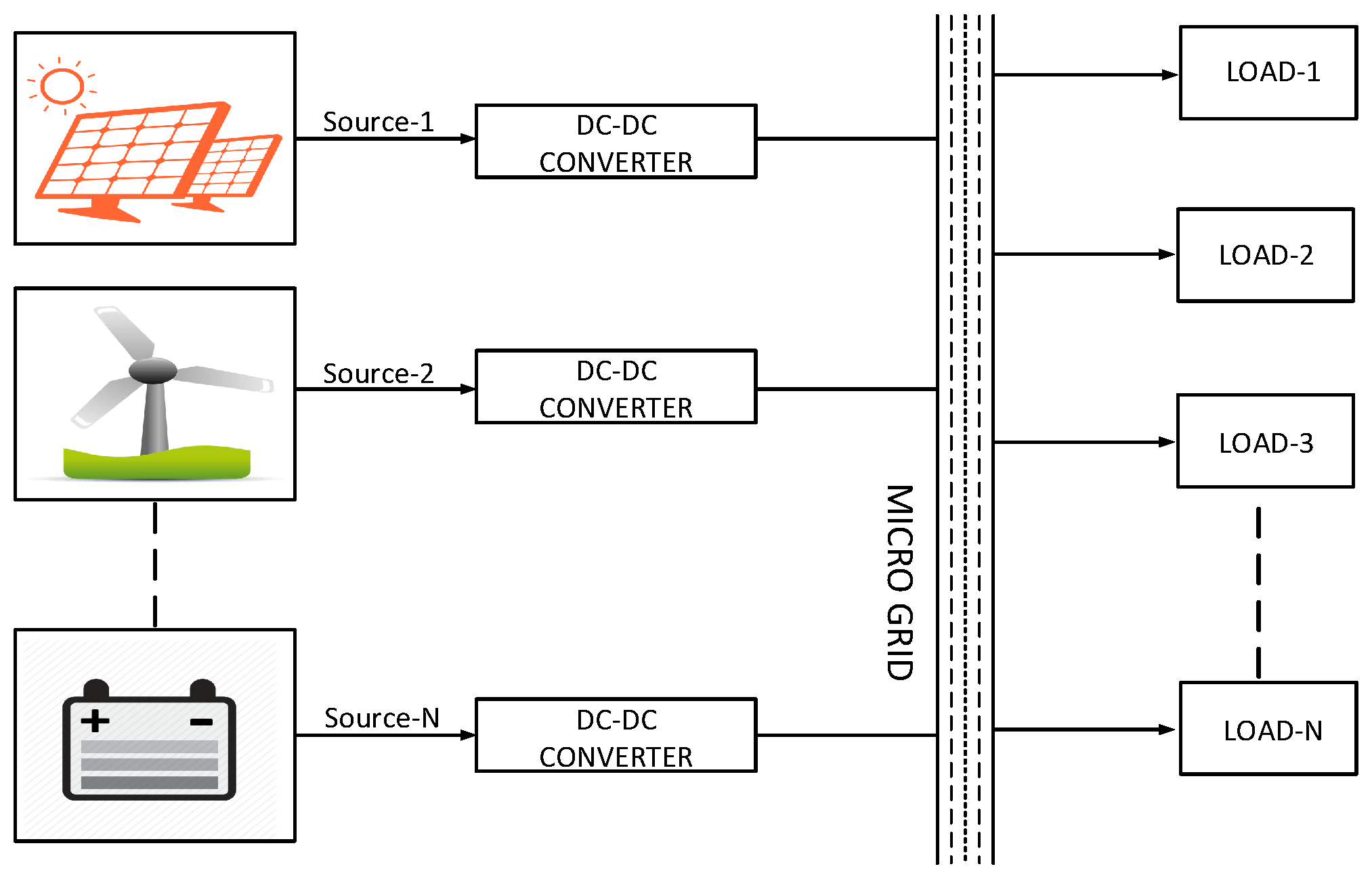
Different energy generation units located at distributed locations are connected to DC micro-grid using DC–DC power electronic converters as shown in Figure 1. The major control problems in this scenario are the voltage regulation and the current sharing among different power sources. Voltage regulation is required for the proper functioning of the load devices, while current sharing is required to ensure that no source is overstressed. These objectives are achieved simultaneously by using a hierarchical control [19,20,21]. Conventionally Proportional Integral Derivative (PID) controllers are used in the voltage and current control loops of these power electronic converters [22]. However, under uncertain load conditions, the gains of the PID controllers require periodic tuning to give the desired performance [23]. The researchers have proposed auto-tuning methods [24] and Fuzzy controllers [25,26] to achieve better results. However, these methods are system dependent and add complexity to the design.
It is reported that the performance improvement is achieved by using boundary layer control [27,28,29], adaptive nonlinear control [30], model predictive control [31,32,33], and a time delayed based robust controller [34]. However, these techniques are not completely parameter independent and require some knowledge of the system specifications like inductance of the coil and capacitance of the filter stage. This calls for the need of a robust controller that can control the nonlinear dynamics of the power converter in order to tightly regulate the voltage in the presence of unknown load demands and uncertain grid parameters.
Indeed, the robustness and parameter invariance [35,36] of Sliding Mode Control (SMC) is well known and makes it an attractive choice for voltage and current control in micro-grids, where load conditions are unknown and network parameters are subject to variations [37,38,39,40,41,42,43]. SMC based techniques result in better voltage regulation in the presence of parametric variations, modeling uncertainties and external disturbances [44,45,46]. However, the major drawback of SMC is its variable switching frequency. Power electronic converters require to operate at fixed switching frequency in order to minimize switching losses [47] and to suppress Electro-Magnetic Interference (EMI) [48]. Hence, the researchers are motivated to combine the advantages of fixed frequency with the robust nature of SMC [49,50,51,52,53,54], thereby reducing EMI emissions and switching losses simultaneously.
However, these techniques are implemented on a single DC–DC converter. To the best of the authors’ knowledge, the behavior of fixed frequency SMC has not been observed yet on the position of a micro-grid.
To fill the above-mentioned research gap, this paper presents a fixed frequency SMC based approach to track the reference voltage of each source connected to the micro-grid. The proposed technique achieves the desired performance by controlling a boost converter that regulates the grid voltage and ensures proper current sharing in the presence of un-modeled dynamics caused by uncertain load and line variations without using observers, which add cost and complexity to the design. The paper contributes in the following three dimensions:
- Improving the dynamic response of the closed loop system and increasing the robustness against unknown load demands in a DC micro-grid, using fixed frequency SMC.
- Designing a novel sliding manifold that results in stable operation of boost converter for wide range of gains, followed by a rigorous mathematical analysis for the stability condition.
- Designing a special test rig with three sources, in order to validate the results in comparison with conventional PI controllers. Moreover, the technique is also tested for fault condition at one of the sources connected to the micro-grid.
It is important to mention that, in case of micro-grids, the electromagnetic interference (EMI) caused by the power lines and switching of the large inductor current, makes the environment less feasible for the use of Digital Signal Processors (DSP) and Field-Programmable Gate Array (FPGA) boards. Therefore, these boards are used in such applications along with specially designed electromagnetic shielding mechanisms to avoid interference from high frequency switching currents. Moreover, they need additional line filters to permit their interaction with the power lines. Due to these reasons, the proposed technique is demonstrated using low cost commercially available analogue Integrated Circuits (ICs), which present a workable industrial solution without involving A/D converters and DSP/FPGA boards which are less immune to EMI and also add additional cost to the design. Moreover, the analogue implementation gives a better picture of the controller design and its implementation procedure.
The article is arranged as follows: mathematical model of the system and controller design are presented in Section 2 and Section 3, respectively. The condition for the existence of sliding mode is described in Section 4. The design of sliding surface and parameterization of the controller is presented in Section 5. The experimental results and discussions are presented in Section 6 while the article is concluded in Section 7.
2. Mathematical Model of the System
Each source in the DC micro grid comprises of a DC–DC converter as shown in Figure 2, where input voltage from the renewable energy source is denoted by , is the instantaneous inductor current, is the output voltage of the converter, is the load resistance, C is the capacitance of the output filter capacitor while L is the inductance of the coil. By using circuit analysis techniques, the nonlinear dynamic model of the system is written as:
where is an unknown but bounded time varying disturbance, which satisfies the condition ; represents the parameter uncertainty caused by Equivalent Series Resistance (ESR) of the capacitor. Since the power electronic switch can be either On or Off, thus mathematically the control signal u belongs to a discrete set: . We define , where the control input u is defined with respect to the power electronic switch as:
The boost converters are nonlinear and non-minimum in-phase with respect to output voltage [55,56] and the dynamics of the inductor current are unstable if the output voltage is considered to be the only variable to be controlled [57]. However, the boost converter satisfies the motion separation principle derived from singular Perturbation Theory [58,59]. It means that the dynamics of are much faster as compared to the dynamics of and the problem can be solved by designing a cascaded control structure with two control loops. The inner loop controls the inductor current while the outer loop controls the load voltage. The inner control loop is designed using fixed frequency SMC while the outer control loop having slower dynamics is designed using PI controller.
Since the controller is robust; therefore, throughout the article, we consider the simplified model with and . The section on experimental results and discussion where the input voltage is varied and sudden changes in load are deliberately applied is an exception in order to evaluate the performance of the controller and verify its robustness. The steady state dynamics of the system are found by setting the time derivatives of system states to zero. Thus, as , and . Setting these values in Equation (1), the reference current in the inner loop is derived as:
where is the reference current for the inner control loop at equilibrium and is the desired output voltage of the converter.
3. Controller Design
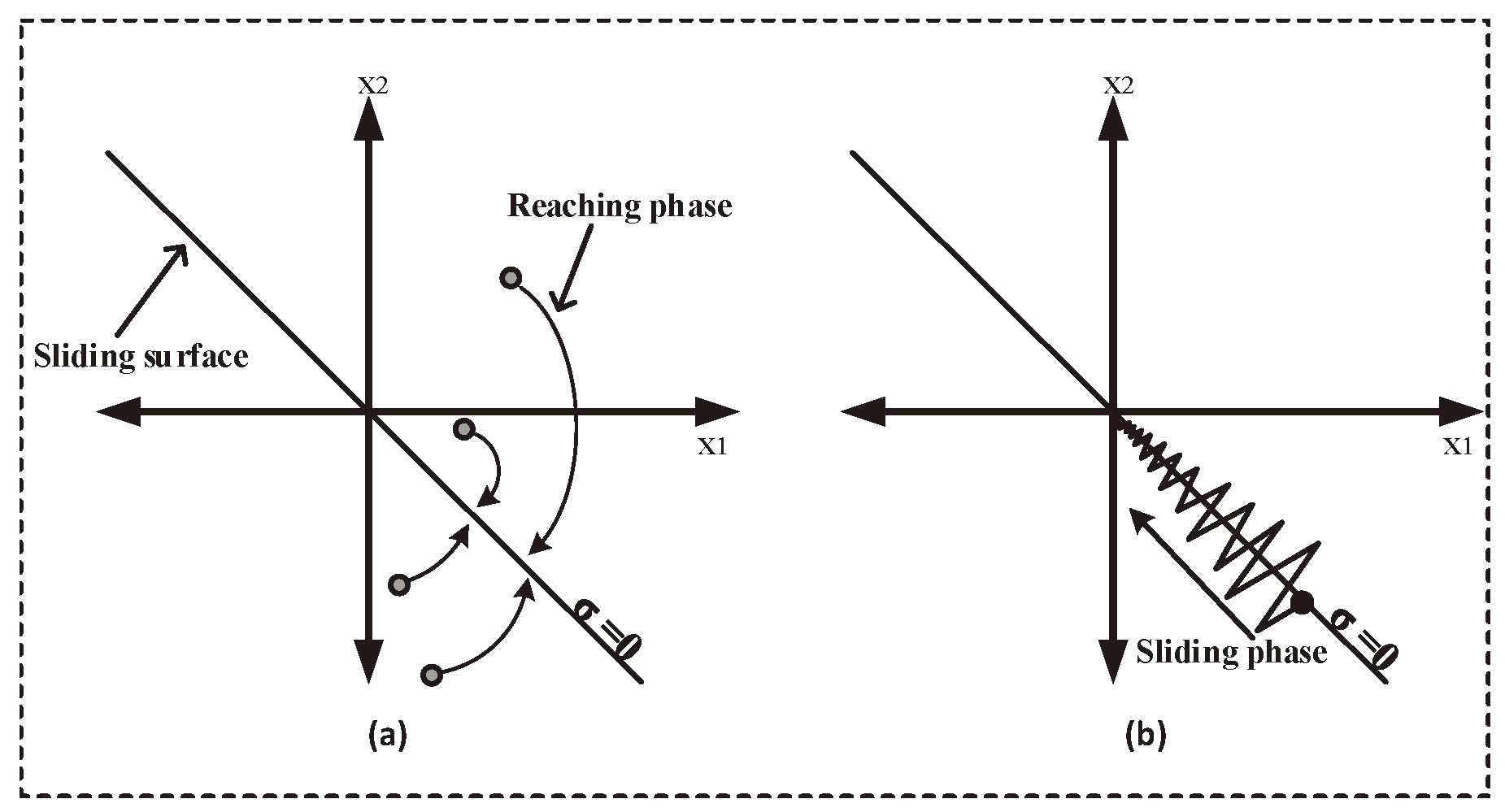
The SMC design concept is based upon a discontinuous control law, which directs the system states towards a sliding manifold in the state space. Sliding manifold is designed to insure the finite time convergence of the state trajectories at the origin. The control process of SMC can be segregated into two phases, namely the reaching phase and the sliding phase. During the reaching phase, the controller generates a series of switching commands such that the state trajectories hit the sliding manifold irrespective to their initial conditions as shown in Figure 3a. In the second phase, the controller executes its operation via switching commands, ensuring the trajectory to be in a small vicinity of the sliding manifold , which in turn gets directed concurrently towards the desired reference at the origin ‘O’ as shown in Figure 3b. In short, the sliding mode operation can be explained such that the controller utilizes the sliding plane as a reference to perform its decisions in order to ensure the convergence of the state trajectories to the origin, where steady state operation is achieved. We select the control law based on the hitting condition [60] as:
The hitting condition ensures that the state trajectories are always directed towards the sliding manifold , regardless of their initial conditions. In order to ensure zero steady state error [61], this paper proposes a double integral type sliding surface given as:
where
and , and are positive design constants. When the state trajectories reach the manifold , sliding mode is said to be established. Now onwards, the system becomes parameter invariant [60] and its behavior is described as:
we differentiate Equation (7) w.r.t time and get:
The Laplace transform of Equation (8) is:
Since , and are positive design constants, hence the Laplace transform in Equation (9) is a Hurwitz polynomial and both of the roots lie on the left side of the S-plane. Hence, as , and .
Implementation of SMC using Pulse Width Modulation (PWM) is based upon two well known theorems. The first theorem [60] states that the discontinuous control u in SMC can be replaced theoretically with a smooth and continuous time function called equivalent control signal, such that . The second theorem states that, at sufficiently high frequency, the equivalent control coincides with the duty ratio of the PWM control [62].
The equivalent control of the system under sliding mode is derived by substituting the time derivative of the sliding surface equal to zero. Thus, setting we get:
Involving the dynamics of the system from Equation (1) and rearranging the terms, we get:
Since the equivalent control signal coincides with the duty ratio d of PWM converter, we can write:
where is the control signal to the PWM modulator and is the peak voltage of ramp signal, respectively. By choosing and using Equation (13), we get:
It is worth mentioning that the proposed structure in Equation (14) differs from the PI controllers because of the term . It acts as an adaptive feedforward gain which automatically changes, in an effort to nullify the disturbances in . This adaptation is also reflected in Equation (15) which means that the peak amplitude of the ramp signal is modified in relation with . It acts as an agent to change the modulation index in order to achieve faster dynamic response. Conditions to guarantee stability and avoid over modulation are discussed in Section 4. Another important difference between the two controllers is the way they are designed. The PI controllers are designed on the concept of small signal analysis which makes the response of the system specific to an operating point while sliding mode controllers are large signal systems, where the design is independent from the operating point.
4. Existence of Sliding Mode Control
The existence and stability of SMC is ensured if the control law enforces the state trajectories towards the sliding manifold . Mathematically, the following two constraints shall be satisfied in the neighborhood of the manifold:
For the proposed controller, we obtain the equation for by using Equations (1) and (5) as:
where and . The specific conditions for the stable operation of the system are as follows:
Case 1:
The control law (4), in Case 1, takes the value . To ensure that Condition (19) remains true, the following constraint shall be satisfied:
The biasing voltages of the operational amplifiers computing and are and , respectively. This physically limits the maximum and minimum values of and . Mathematically, and ; thus, by appropriate choice of design constants , and , the constraint in Equation (20) is satisfied.
Case 2:
When , then Constrain (17) states that . This turns Equation (18) into inequality as:
The control law will turn . To ensure that condition in Inequality (21) remains true, the following constraint shall be satisfied:
The Inequality (22) is satisfied by an appropriate choice of design constants. It is important to notice that, if the output voltage of the converter is less than the input source voltage, then the inequality (22) is not satisfied. This requires careful selection of the initial conditions that guarantee the convergence of the state trajectories to . At startup of the boost converter, this problem is solved by starting the converter in open loop and then closing the loop once the condition is satisfied. Another simple way to solve the problem is by introducing a protection circuit that always ensures the control signal in the PWM circuit, which in return results in stable switching of the power electronic switch until the condition is achieved.
5. Sliding Surface and Parametrization of the Controller
In order to achieve the desired dynamics of the system during sliding mode, the controller is parametrized using Ackermann’s formula. When the system is sliding on the manifold , then the reduced order dynamics of the system are totally described by the sliding coefficients. Rearranging Equation (8), we get:
The standard second order equation is given as:
Comparing coefficients of the Equations (23) with (24), we get:
where is the natural frequency and is the damping ratio. Recalling that the damping ratio in a linear time-invariant second order system corresponds to the response of the system, which is over damped for , critically damped for and under damped for . In order to achieve a smooth and fast response with no overshoots, we choose . Rearranging the above equation in terms of the bandwidth of the converter, we get:
For the desired bandwidth of 65 kHz, the calculations of the sliding coefficients using Equation (25) are as follows:
It is important mention that the maximum allowable limits of the op-amps should be considered while parameterizing the controller. In our case, both and of the converter exceed the limits. This problem is solved by feeding and via voltage divider network with attenuation constant . For the desired output voltage of V, the reference voltage is kept as 2.5 V. Hence, is calculated as:
The combination of feedback resistor is calculated using . Selecting resistor as , is calculated as:
Using a series combination of standard value resistors, we get . The constant modifies the feedback control Equation (13) as:
where is computed from Equation (14) as:
The output of op-amps computing and in Equation (18) are also scaled by the constant such that:
The integrator in Equation (27) is designed using op-amp circuit, where gain . By selecting pF, the value of is calculated as:
The outer PI control loop has a proportional gain of 8.2 and an integral gain of . The integral gain is achieved by selecting F and . In order to limit the maximum duty cycle of the power converter to 95%, a shunt regulator using TL431 with its reverse breakdown voltage adjusted at V is placed at the output of the operational amplifier generating the control signal . TL431 cannot be adjusted to regulate the output voltage lower than V, hence a summing gain of 2 is introduced so that the signal is greater than the minimum regulated voltage of TL431. This gain is then compensated in Equation (13) by amplifying the ramp peak by the same gain. The hardware implementation of and is given as:
6. Experimental Results and Discussion
In the experimentation, Matrix power supplies having precision to one decimal place are used to test the performance of the controller under varying input voltages and changing load conditions. The experimental results are obtained using a two channel Rigol oscilloscope having 70 MHz bandwidth and sampling rate of 1 GHz. To test the wide range operation of the boost converter, the outdoor experiment is performed using solar panels and measurements are taken with regular intervals.
The parameters of DC–DC converter are selected on the basis of 250 W output power. The inductance of the coil is 100 H and the output filter capacitor is of 1000 F. Power Metal-Oxide- Semiconductor Field-Effect Transistor (MOSFET) (IRF540) with on-resistance of 0.06 and continuous drain current capability of 20 A is selected as an electronic switch. Fixed switching frequency for the sliding mode operation is selected to be 50 kHz and the experimental setup is shown in Figure 4. The efficiency of the converter at this frequency is experimentally observed to be 90.06% when delivering 7 W to the load. It is observed that, in order to ensure the efficient switching, the resistance seen by the MOSFET at its drain shall be kept less than 47 so as to keep the discharge interval of body diode capacitance of the MOSFET, less than its switching interval under SMC. A reference signal of 2.5 V is generated using adjustable shunt regulator TL431 with its reference pin connected to its cathode. Due to the uni-directional nature of inductor current, it is not possible to measure it using a current transformer (CT). To measure , a resistor is placed in its return path. As flows, a voltage is developed across and we measure the inductor current as:
6.1. Open Loop Response
In order to emphasize the need of the feedback control, the open loop response of the system is presented in Figure 5. The converter is operated, in open loop with a PWM signal having a 50% duty ratio. The calculated output of the converter at this signal is 24 V, but the experimental output is 22.8 V, which is 1.2 V less than the calculated output. This difference occurs due to the voltage drop in the parasitic resistance of the hardware components and the connecting leads. The output further drops to 20 V when an additional load of 47 is connected to the existing 82 load. Hence, it may be concluded that in open loop, the output of the power converter exhibits a steady state error that changes with variation in load resistors.
6.2. Comparison with Current Mode Controller
The performance of the proposed technique is analyzed along with the conventional current-mode controller, having a PI loop each for voltage regulation and current tracking. For the sake of comparison, the bandwidth of the proposed technique is set to be the same as the current-mode controller. The circuit diagram for voltage regulation in a single source is shown in Figure 6.
6.2.1. Dynamic Response
The dynamic response of the current-mode PI controller is presented in Figure 7a. The controller achieves 24 V with rise time of 41 ms and settles to final value in 80 ms. Figure 7b shows the response of the proposed fixed frequency SMC. The proposed controller has rise time of 40 ms and settling time of 75 ms. The results show an improvement of 2.5% in the rise time and 6.66% in the settling time of the closed loop system. The response is faster as compared to the current-mode PI controller due to the presence of a feedforward term in the proposed technique.
The switching sequence generated by the controller is shown in Figure 8a. The drain voltage resulting due to switching of MOSFET is shown on CH1 in Figure 8b. The CH2 in the same figure shows the inductor current. It shall be noticed that the time period of switching sequence is constant, hence the objective of fixing the switching frequency in SMC is achieved by the proposed technique.
The hardware can be easily scaled for operation at any desired output by proper selection of . The value of shall be selected such that the feedback signal does not exceed the power supply voltages of the operational amplifiers and other control circuitry. In order to observe the behavior of the controller for high voltage and large power applications, the technique is also applied to the converter with specifications shown in Table 1. The experimental setup is shown in Figure 4b where the input voltage is applied using four 12 V lead acid batteries connected in series having 200 AH current rating. The output is regulated at 110 V while delivering 1230 W to the load. Figure 9a shows the inductor current that is measured using a current to voltage conversion circuit while the dynamic response of the converter is shown in Figure 9b. For the sake of analysis, the output voltage is fed to the oscilloscope through a resistive network of 0.1 attenuation and is measured using its 10× settings.
6.2.2. Robustness of the Controller
The robustness of the controller is verified by applying a step change in load from 82 to 29.9 . This step change is emulated by connecting and disconnecting a 47 resistor in parallel with 82 load at a frequency of 10 KHz. The switching is achieved by using a Darlington paired Positive-Negative-Positive (PNP) power transistor (TIP142) whose base is driven by Negative-Positive-Negative (NPN) transistor (C828). Figure 10a shows that the conventional current-mode controller exhibits an undershoot of 4.1 V and recovers in 640 s. Figure 10b shows that the proposed DI-SMC exhibits an under-shoot of only 2.8 V and recovers in 250 s with no steady state error. Hence, the voltage dip during load transaction is reduced by 31.7%. This verifies the robustness of the proposed technique to a sudden change in load which is a key feature of SMC designs. The experimental setup for the proposed controller is shown in Figure 4. The proposed controller is also tested for line variations. The test is performed by changing the input voltage from V to V. The controller operates effectively and the results are summarized in Table 2.
6.3. Grid Testing for Fault Condition
The capability of the proposed technique to operate in a DC micro-grid is experimentally validated on a test rig comprising of three sources. An outer control loop based on a PI-controller provides reference current signal for the each source connected to the micro-grid. The tracking of the reference current is accomplished in each source by using a boost converter controlled by the proposed double integral type fixed frequency SMC. During the steady state condition, the bus voltage is 24 V and the currents supplied by the sources are 1.61 A, 1.63 A and 1.62 A, respectively. The system is operated at a partial load such that, if one source fails, the other two sources have sufficient power capability to fulfill the load demand. The fault in Source 2 is emulated by disconnecting its control signal. Figure 11a–c show the current of each source during the fault condition. Figure 11d shows the voltage transient at the load during the fault. The new currents supplied by Sources 1 and 3 are 2.42 A and 2.44 A, respectively, which corresponds to 0.82% error in load sharing. Hence, the load disturbances on the position of DC–DC micro-grids have been effectively addressed, confirming that the proposed technique is capable of operation even during an instantaneous increase in the load demand or in case of a fault in the connected sources.
7. Conclusions
In this paper, voltage regulation of DC micro-grid using fixed frequency SMC with a novel double integral type sliding manifold is proposed along with a rigorous proof for the stability of the system. The controller is tested experimentally and the results show the desired performance of the proposed technique along with providing robustness against fluctuations in input voltages and change in load conditions. A detailed discussion on parametrization of the controller, hardware design and circuit implementation is presented. The technique is also applied on a micro-grid test bench, having three sources and the results show satisfactory operation of the closed loop system. The controller is implemented using commercially available analogue ICs which eliminated the need of using expensive analogue-to-digital data accusation cards along with phasing out the issues due to their finite sampling time. For the purpose of bench marking, the results are compared with conventional PI controller. The proposed technique improved the dynamic response of the closed loop system by reducing both, the rise time and the settling time by 2.5% and 6.7%, respectively. It is observed that a sudden voltage dip appears in the regulated voltage when an additional load is connected. This dip is reduced by 31.7% for the proposed controller as compared to that of the conventional PI controller.
The future work may be extended to the study of the proposed technique in more diverse networks including different types of power converters, controlled by various local techniques, other than the one presented in this research.
Author Contributions
A.R.Y. has conducted the research and written the manuscript under the supervision of M.A. A.I.B. has helped in driving mathematical expressions for the existence of the sliding mode control.
Funding
This research received no external funding.
Acknowledgments
The authors would like to thank the Capital University of Science and Technology.
Conflicts of Interest
The authors declare no conflict of interest.
Abbreviations
The following abbreviations are used in this manuscript:
| AC | Alternating Current |
| BJT | Bipolar Junction Transistor |
| DC | Direct Current |
| DGU | Distributed Generation Units |
| DSP | Digital Signal Processors |
| EMI | Electromagnetic Interference |
| FPGA | Field-Programmable Gate Array |
| LED | Light Emitting Diode |
| Li-ion | Lithium-ion |
| MOSFET | Metal Oxide Field-Effect Transistor |
| Ni-Cd | Nickel-Cadmium |
| PID | Proportional Integral Derivative |
| PI | Proportional Integral |
| PWM | Pulse Width Modulation |
| PV | Photo-Voltaic |
| RER | Renewable Energy Resources |
| SMC | Sliding Mode Control |
| C | Capacitance |
| Attenuation Constant | |
| Bandwidth of the Converter | |
| u | Control Input |
| Control Signal | |
| Damping Ratio | |
| Design Constants | |
| Desired Output Voltage | |
| d | Duty Ratio |
| Equivalent Control | |
| Error Signal | |
| Inductor Current | |
| L | Inductor of coil |
| Input Voltage | |
| Load Resistor | |
| Output Voltage | |
| Peak Amplitude of Modulating Ramp | |
| Reference Current | |
| Reference Voltage | |
| Sliding Manifold |
References
- Díaz, N.L.; Luna, A.C.; Vasquez, J.C.; Guerrero, J.M. Centralized control architecture for coordination of distributed renewable generation and energy storage in islanded ac microgrids. IEEE Trans. Power Electron. 2017, 32, 5202–5213. [Google Scholar] [CrossRef] [Green Version]
- Faria, P.; Spínola, J.; Vale, Z. Distributed Energy Resources Scheduling and Aggregation in the Context of Demand Response Programs. Energies 2018, 11, 1987. [Google Scholar] [CrossRef]
- Dörfler, F.; Simpson-Porco, J.W.; Bullo, F. Breaking the Hierarchy: Distributed Control and Economic Optimality in Microgrids. IEEE Trans. Control Netw. Syst. 2016, 3, 241–253. [Google Scholar] [CrossRef]
- Jin, M.; Feng, W.; Marnay, C.; Spanos, C. Microgrid to enable optimal distributed energy retail and end-user demand response. Appl. Energy 2018, 210, 1321–1335. [Google Scholar] [CrossRef] [Green Version]
- Antunez, P.D.; Bishop, D.M.; Luo, Y.; Haight, R. Efficient kesterite solar cells with high open-circuit voltage for applications in powering distributed devices. Nat. Energy 2017, 2, 884. [Google Scholar] [CrossRef]
- Bhowmik, C.; Bhowmik, S.; Ray, A.; Pandey, K.M. Optimal green energy planning for sustainable development: A review. Renew. Sustain. Energy Rev. 2017, 71, 796–813. [Google Scholar] [CrossRef]
- Mohan, N.; Undeland, T.M. Power Electronics: Converters, Applications, and Design; John Wiley & Sons: Hoboken, NJ, USA, 2007. [Google Scholar]
- Ivanovic, Z.; Blanusa, B.; Knezic, M. Power loss model for efficiency improvement of boost converter. In Proceedings of the 2011 XXIII International Symposium on Information, Communication and Automation Technologies, Sarajevo, Bosnia and Herzegovina, 27–29 October 2011; pp. 1–6. [Google Scholar]
- Lotfi, H.; Khodaei, A. AC versus DC microgrid planning. IEEE Trans. Smart Grid 2017, 8, 296–304. [Google Scholar] [CrossRef]
- Dragicevic, T.; Vasquez, J.C.; Guerrero, J.M.; Skrlec, D. Advanced LVDC Electrical Power Architectures and Microgrids: A step toward a new generation of power distribution networks. IEEE Electrif. Mag. 2014, 2, 54–65. [Google Scholar] [CrossRef]
- Wang, C.; Duan, J.; Fan, B.; Yang, Q.; Liu, W. Decentralized High-Performance Control of DC Microgrids. IEEE Trans. Smart Grid 2018. [Google Scholar] [CrossRef]
- Cairoli, P.; Dougal, R.A. Fault Detection and Isolation in Medium-Voltage DC Microgrids: Coordination between Supply Power Converters and Bus Contactors. IEEE Trans. Power Electron. 2018, 33, 4535–4546. [Google Scholar] [CrossRef]
- Saleh, M.; Esa, Y.; Mohamed, A. Communication Based Control for DC Microgrids. IEEE Trans. Smart Grid 2018. [Google Scholar] [CrossRef]
- Dehkordi, N.M.; Baghaee, H.R.; Sadati, N.; Guerrero, J.M. Distributed Noise-resilient Secondary Voltage and Frequency Control for Islanded Microgrids. IEEE Trans. Smart Grid 2018. [Google Scholar] [CrossRef]
- Mousavi, S.Y.M.; Jalilian, A.; Savaghebi, M.; Guerrero, J.M. Coordinated control of multifunctional inverters for voltage support and harmonic compensation in a grid-connected microgrid. Electr. Power Syst. Res. 2018, 155, 254–264. [Google Scholar] [CrossRef] [Green Version]
- Sun, K.; Zhang, L.; Xing, Y.; Guerrero, J.M. A Distributed Control Strategy Based on DC Bus Signaling for Modular Photovoltaic Generation Systems With Battery Energy Storage. IEEE Trans. Power Electron. 2011, 26, 3032–3045. [Google Scholar] [CrossRef] [Green Version]
- Schonbergerschonberger, J.; Duke, R.; Round, S.D. DC-Bus Signaling: A Distributed Control Strategy for a Hybrid Renewable Nanogrid. IEEE Trans. Ind. Electron. 2006, 53, 1453–1460. [Google Scholar] [CrossRef] [Green Version]
- Alizadeh, E.; Birjandi, A.M.; Hamzeh, M. Decentralised power sharing control strategy in LV microgrids under unbalanced load conditions. IET Gener. Transm. Distrib. 2017, 11, 1613–1623. [Google Scholar] [CrossRef]
- Cucuzzella, M.; Trip, S.; De Persis, C.; Cheng, X.; Ferrara, A.; van der Schaft, A. A robust consensus algorithm for current sharing and voltage regulation in dc microgrids. IEEE Trans. Control Syst. Technol. 2018. [Google Scholar] [CrossRef]
- Kakigano, H.; Miura, Y.; Ise, T.; Uchida, R. DC voltage control of the DC micro-grid for super high quality electric power distribution. IEEE Trans. Ind. Appl. 2007, 127, 890–897. [Google Scholar] [CrossRef]
- Han, R.; Meng, L.; Guerrero, J.M.; Vasquez, J.C. Distributed nonlinear control with event-triggered communication to achieve current-sharing and voltage regulation in DC microgrids. IEEE Trans. Power Electron. 2018, 33, 6416–6433. [Google Scholar] [CrossRef]
- Guerrero, J.M.; Vasquez, J.C.; Matas, J.; de Vicuna, L.G.; Castilla, M. Hierarchical Control of Droop-Controlled AC and DC Microgrids 2014;A General Approach Toward Standardization. IEEE Trans. Ind. Electron. 2011, 58, 158–172. [Google Scholar] [CrossRef]
- Wai, R.J.; Shih, L.C. Design of voltage tracking control for DC–DC boost converter via total sliding-mode technique. IEEE Trans. Ind. Electron. 2011, 58, 2502–2511. [Google Scholar] [CrossRef]
- Shirazi, M.; Zane, R.; Maksimovic, D. An autotuning digital controller for DC–DC power converters based on online frequency-response measurement. IEEE Trans. Power Electron. 2009, 24, 2578–2588. [Google Scholar] [CrossRef]
- Guo, L.; Hung, J.Y.; Nelms, R.M. Evaluation of DSP-Based PID and Fuzzy Controllers for DC 2013;DC Converters. IEEE Trans. Ind. Electron. 2009, 56, 2237–2248. [Google Scholar] [CrossRef]
- Lee, M.; Chen, D.; Huang, K.; Liu, C.W.; Tai, B. Modeling and Design for a Novel Adaptive Voltage Positioning (AVP) Scheme for Multiphase VRMs. IEEE Trans. Power Electron. 2008, 23, 1733–1742. [Google Scholar] [CrossRef]
- Onwuchekwa, C.N.; Kwasinski, A. Analysis of Boundary Control for Buck Converters With Instantaneous Constant-Power Loads. IEEE Trans. Power Electron. 2010, 25, 2018–2032. [Google Scholar] [CrossRef] [Green Version]
- Galvez, J.M.; Ordonez, M.; Luchino, F.; Quaicoe, J.E. Improvements in Boundary Control of Boost Converters Using the Natural Switching Surface. IEEE Trans. Power Electron. 2011, 26, 3367–3376. [Google Scholar] [CrossRef]
- Kirshenboim, O.; Peretz, M.M. Stability Analysis of Boundary and Hybrid Controllers for Indirect Energy Transfer Converters. IEEE Trans. Power Electron. 2016, 31, 3360–3371. [Google Scholar] [CrossRef]
- Linares-Flores, J.; Méndez, A.H.; García-Rodríguez, C.; Sira-Ramírez, H. Robust Nonlinear Adaptive Control of a Boost Converter via Algebraic Parameter Identification. IEEE Trans. Ind. Electron. 2014, 61, 4105–4114. [Google Scholar] [CrossRef]
- Cavanini, L.; Cimini, G.; Ippoliti, G.; Bemporad, A. Model predictive control for pre-compensated voltage mode controlled DC–DC converters. IET Control Theory Appl. 2017, 11, 2514–2520. [Google Scholar] [CrossRef]
- Kim, S.K.; Park, C.R.; Kim, J.S.; Lee, Y.I. A stabilizing model predictive controller for voltage regulation of a DC/DC boost converter. IEEE Trans. Control Syst. Technol. 2014, 22, 2016–2023. [Google Scholar] [CrossRef]
- Karamanakos, P.; Geyer, T.; Manias, S. Direct voltage control of dc–dc boost converters using enumeration-based model predictive control. IEEE Trans. Power Electron. 2014, 29, 968–978. [Google Scholar] [CrossRef]
- Wang, Y.X.; Yu, D.H.; Kim, Y.B. Robust Time-Delay Control for the DC–DC Boost Converter. IEEE Trans. Ind. Electron. 2014, 61, 4829–4837. [Google Scholar] [CrossRef]
- Utkin, V.I. Sliding mode control design principles and applications to electric drives. IEEE Trans. Ind. Electron. 1993, 40, 23–36. [Google Scholar] [CrossRef] [Green Version]
- Calvente, J.; El Aroudi, A.; Giral, R.; Cid-Pastor, A.; Vidal-Idiarte, E.; Martínez-Salamero, L. Design of Current Programmed Switching Converters Using Sliding-Mode Control Theory. Energies 2018, 11, 2034. [Google Scholar] [CrossRef]
- Delghavi, M.B.; Yazdani, A. Sliding-Mode Control of AC Voltages and Currents of Dispatchable Distributed Energy Resources in Master-Slave-Organized Inverter-Based Microgrids. IEEE Trans. Smart Grid 2017. [Google Scholar] [CrossRef]
- Pilloni, A.; Pisano, A.; Usai, E. Robust Finite-Time Frequency and Voltage Restoration of Inverter-Based Microgrids via Sliding-Mode Cooperative Control. IEEE Trans. Ind. Electron. 2018, 65, 907–917. [Google Scholar] [CrossRef]
- Dou, C.; Zhang, B.; Yue, D.; Zhang, Z.; Xu, S.; Hayat, T.; Alsaedi, A. A Novel Hierarchical Control Strategy Combined with Sliding Mode Control and Consensus Control for Islanded Micro-grid. IET Renew. Power Gener. 2018, 12, 1012–1024. [Google Scholar] [CrossRef]
- Fu, Y.; Zhang, H.; Mi, Y.; Huang, L.; Li, Z.; Wang, J. Control strategy of DFIG in hybrid micro-grid using sliding mode frequency controller and observer. IET Gener. Transm. Distrib. 2018, 12, 2662–2669. [Google Scholar] [CrossRef]
- Shinde, U.K.; Kadwane, S.G.; Gawande, S.P.; Reddy, M.J.B.; Mohanta, D.K. Sliding Mode Control of Single-Phase Grid-Connected Quasi-Z-Source Inverter. IEEE Access 2017, 5, 10232–10240. [Google Scholar] [CrossRef]
- Zhu, Y.; Fei, J. Adaptive Global Fast Terminal Sliding Mode Control of Grid-connected Photovoltaic System Using Fuzzy Neural Network Approach. IEEE Access 2017, 5, 9476–9484. [Google Scholar] [CrossRef]
- Ghiasi, M.I.; Golkar, M.A.; Hajizadeh, A. Lyapunov Based-Distributed Fuzzy-Sliding Mode Control for Building Integrated-DC Microgrid With Plug-In Electric Vehicle. IEEE Access 2017, 5, 7746–7752. [Google Scholar] [CrossRef] [Green Version]
- Utkin, V. Sliding mode control of DC/DC converters. J. Frankl. Inst. 2013, 350, 2146–2165. [Google Scholar] [CrossRef] [Green Version]
- Teja, A.R.; Chakraborty, C.; Pal, B.C. Disturbance Rejection Analysis and FPGA based Implementation of a Second Order Sliding Mode Controller fed Induction Motor Drive. IEEE Trans. Energy Convers. 2018, 33, 1453–1462. [Google Scholar] [CrossRef]
- Yang, B.; Yu, T.; Shu, H.; Dong, J.; Jiang, L. Robust sliding-mode control of wind energy conversion systems for optimal power extraction via nonlinear perturbation observers. Appl. Energy 2018, 210, 711–723. [Google Scholar] [CrossRef]
- Tan, S.C.; Lai, Y.M.; Cheung, M.K.H.; Tse, C.K. On the practical design of a sliding mode voltage controlled buck converter. IEEE Trans. Power Electron. 2005, 20, 425–437. [Google Scholar] [CrossRef] [Green Version]
- Pareschi, F.; Rovatti, R.; Setti, G. EMI Reduction via Spread Spectrum in DC/DC Converters: State of the Art, Optimization, and Tradeoffs. IEEE Access 2015, 3, 2857–2874. [Google Scholar] [CrossRef]
- Mohanty, P.R.; Panda, A.K. Fixed-Frequency Sliding-Mode Control Scheme Based on Current Control Manifold for Improved Dynamic Performance of Boost PFC Converter. IEEE J. Emerg. Sel. Top. Power Electron. 2017, 5, 576–586. [Google Scholar] [CrossRef]
- He, Y.; Luo, F. Sliding-mode control for dc–dc converters with constant switching frequency. IEE Proc. Control Theory Appl. 2006, 153, 37–45. [Google Scholar] [CrossRef]
- Ye, J.; Malysz, P.; Emadi, A. A fixed-switching-frequency integral sliding mode current controller for switched reluctance motor drives. IEEE J. Emerg. Sel. Top. Power Electron. 2015, 3, 381–394. [Google Scholar]
- Abeywardana, D.B.W.; Hredzak, B.; Agelidis, V.G. A fixed-frequency sliding mode controller for a boost-inverter-based battery-supercapacitor hybrid energy storage system. IEEE Trans. Power Electron. 2017, 32, 668–680. [Google Scholar] [CrossRef]
- Gao, M.; Wang, D.; Li, Y.; Yuan, T. Fixed frequency pulse-width modulation based integrated sliding mode controller for phase-shifted full-bridge converters. IEEE Access 2018, 6, 2181–2192. [Google Scholar] [CrossRef]
- Chincholkar, S.H.; Chan, C.Y. Design of fixed-frequency pulsewidth-modulation-based sliding-mode controllers for the quadratic boost converter. IEEE Trans. Circuits Syst. II Express Briefs 2017, 64, 51–55. [Google Scholar] [CrossRef]
- Sira-Ramirez, H. Sliding-mode control on slow manifolds of DC-to-DC power converters. Int. J. Control 1988, 47, 1323–1340. [Google Scholar] [CrossRef]
- Shahir, F.M.; Babaei, E.; Farsadi, M. Extended Topology for Boost DC–DC Converter. IEEE Trans. Power Electron. 2018. [Google Scholar] [CrossRef]
- Alsmadi, Y.M.; Utkin, V.; Haj-ahmed, M.A.; Xu, L. Sliding mode control of power converters: DC/DC converters. Int. J. Control 2017, 1–22. [Google Scholar] [CrossRef]
- Kokotovic, P.V.; O’malley, R.; Sannuti, P. Singular perturbations and order reduction in control theory—An overview. Automatica 1976, 12, 123–132. [Google Scholar] [CrossRef]
- Kokotović, P.V. Applications of singular perturbation techniques to control problems. SIAM Rev. 1984, 26, 501–550. [Google Scholar] [CrossRef]
- Utkin, V.; Guldner, J.; Shi, J. Sliding Mode Control in Electro-Mechanical Systems; CRC Press: Boca Raton, FL, USA, 2009; Volume 34. [Google Scholar]
- Tan, S.C.; Lai, Y.; Tse, C.K. Indirect sliding mode control of power converters via double integral sliding surface. IEEE Trans. Power Electron. 2008, 23, 600. [Google Scholar]
- Sira-Ramirez, H.; Ilic, M. A geometric approach to the feedback control of switch mode DC-to-DC power supplies. IEEE Trans. Circuits Syst. 1988, 35, 1291–1298. [Google Scholar] [CrossRef]
Figure 1.
Connection of distributed energy resources to a Direct Current (DC) micro-grid.

Figure 2.
Simplified scheme for the voltage and current control using DC–DC boost converter.

Figure 3.
State space trajectories under Sliding Mode Control (SMC). (a) reaching phase; (b) sliding phase.
Figure 3.
State space trajectories under Sliding Mode Control (SMC). (a) reaching phase; (b) sliding phase.

Figure 4.
Experimental set-up for the proposed technique. (a) 24 V setup; (b) 110 V setup.

Figure 5.
Output voltage of the boost converter in an open loop during rated load and full load.

Figure 6.
Schematic diagram of the proposed technique for voltage regulation in a single source using boost converter.
Figure 6.
Schematic diagram of the proposed technique for voltage regulation in a single source using boost converter.

Figure 7.
Step response of the system. (a) conventional current-mode controller; (b) fixed frequency Double Integral Sliding Mode Control (DI-SMC).
Figure 7.
Step response of the system. (a) conventional current-mode controller; (b) fixed frequency Double Integral Sliding Mode Control (DI-SMC).

Figure 8.
Fixed frequency operation of the converter. (a) switching signal; (b) drain voltage and inductor current.
Figure 8.
Fixed frequency operation of the converter. (a) switching signal; (b) drain voltage and inductor current.

Figure 9.
Performance of the DI-SMC during large power application. (a) inductor current; (b) step response.
Figure 9.
Performance of the DI-SMC during large power application. (a) inductor current; (b) step response.

Figure 10.
Experiment waveform of the output voltage when an additional load of 47 is connected in parallel to 82 load. (a) conventional current-mode controller; (b) fixed frequency DI-SMC.
Figure 10.
Experiment waveform of the output voltage when an additional load of 47 is connected in parallel to 82 load. (a) conventional current-mode controller; (b) fixed frequency DI-SMC.

Figure 11.
Grid operation of DI-SMC. (a) output current of Source-1; (b) output current of Source-2; (c) output current of Source-3. (d) Load voltage during fault condition.
Figure 11.
Grid operation of DI-SMC. (a) output current of Source-1; (b) output current of Source-2; (c) output current of Source-3. (d) Load voltage during fault condition.


Table 1.
Parameters of power converter.
| Parameter | Value |
|---|---|
| Input Voltage | 55 V |
| Output Voltage | 110 V |
| Inductance of Coil | 100 H |
| Output capacitance | 1000 F |
| Max. Output power | 2000 W |
Table 2.
Output voltages for variations in input.
| 12.1 | 24.0 |
| 14.5 | 24.0 |
| 16.0 | 24.0 |
| 18.1 | 24.0 |
© 2018 by the authors. Licensee MDPI, Basel, Switzerland. This article is an open access article distributed under the terms and conditions of the Creative Commons Attribution (CC BY) license (http://creativecommons.org/licenses/by/4.0/).
Share and Cite
MDPI and ACS Style
Yasin, A.R.; Ashraf, M.; Bhatti, A.I. Fixed Frequency Sliding Mode Control of Power Converters for Improved Dynamic Response in DC Micro-Grids. Energies 2018, 11, 2799. https://doi.org/10.3390/en11102799
AMA Style
Yasin AR, Ashraf M, Bhatti AI. Fixed Frequency Sliding Mode Control of Power Converters for Improved Dynamic Response in DC Micro-Grids. Energies. 2018; 11(10):2799. https://doi.org/10.3390/en11102799
Chicago/Turabian StyleYasin, Abdul Rehman, Muhammad Ashraf, and Aamer Iqbal Bhatti. 2018. "Fixed Frequency Sliding Mode Control of Power Converters for Improved Dynamic Response in DC Micro-Grids" Energies 11, no. 10: 2799. https://doi.org/10.3390/en11102799
Note that from the first issue of 2016, this journal uses article numbers instead of page numbers. See further details here.