Mechanism Analysis of Liquid Carbon Dioxide Phase Transition for Fracturing Rock Masses

School of Resources and Safety Engineering, Central South University, Changsha 410083, China
*
Author to whom correspondence should be addressed.
Energies 2018, 11(11), 2909; https://doi.org/10.3390/en11112909
Submission received: 3 September 2018
/
Revised: 20 October 2018
/
Accepted: 23 October 2018
/
Published: 25 October 2018
(This article belongs to the Special Issue New Stimulation Methods for Recovery of Energy and Minerals from Ultra-low-permeability Rock Formations)
Abstract
:The technique of breaking rocks using carbon dioxide phase transition technology is being widely applied in current research. This article combines theoretical and practical methods to analyze the mechanism by which high-pressure gas breaks rock at different stages. Using the observation that liquid carbon dioxide forms a high-pressure jet from release holes at the moment of release, a formula for calculating the initial pressure on the wall in the direction of release was obtained, and the pattern of initial crack formation on the borehole wall under different initial stress conditions was examined. An experiment using carbon dioxide phase transition technology to fracture rock without an initial stress field was conducted. The mechanism of generation and expansion of subsequent cracks under stress waves and high-pressure gas was analyzed, and the formula for calculating crack propagation radius under stress waves was obtained. The results suggested that under the quasi-static action of high-pressure gas, cracks begin to develop when the stress intensity factor KI at the crack tip is equal to or greater than the fracture toughness KIC of the rock.
1. Introduction
Liquid carbon dioxide phase transition technology can be dated to the 1940s in the United States [1]. This technology uses physical blasting and has the following advantages: A non-explosive spark, no toxic gases, and high security and manageability [2]. In the 1950s, a liquid carbon dioxide phase transition device was invented by a British company called CARDOX, enabling wider commercial application [3,4]. In the 1980s, the technology developed rapidly. Specifically, in the past ten years, liquid carbon dioxide phase transition has been used for underground coal mining, surface mining, tunneling [5], material molding [6], and cleaning maintenance field [7].
Currently, research on the use of liquid carbon dioxide phase transition technology for fracturing rock masses has focused on coal mining and oil and gas recovery. Early research focused on the mechanism of high-pressure gas activity. For example, carbon dioxide released by liquid carbon dioxide blasting can break coal or explosive material along natural cracks [8]. Xu Ying began research on high-pressure gas blasting systems in the 1990s. He developed a simulated experiment system for high-pressure gas blasting and studied the mechanism and crushing size of the high-pressure gas blasting action on coal [9]. Sun Keming et al. simulated the generation of initial cracks in coal from supercritical carbon dioxide blasting using an experimental method. This study showed that when the impact of the carbon dioxide explosion exceeds the dynamic compressive strength of the coal around the blasting hole, a crushing zone is formed. The radial displacement of the media outside the crushing zone is generated by the action of the stress wave, which generates the circumferential tensile stress. In addition to the gas wedging effect of the detonation gas, when the circumferential tensile stress exceeds the dynamic tensile strength of the coal body, a cracking zone is formed [10]. Subsequent research about the blasting energy, crack pipe structure, and blasting parameters used during the process of liquid carbon dioxide phase transition has been conducted. For example, Lu Tingkan and Wang Zhaofeng gave two formulas for calculating the explosive energy generated by liquid carbon dioxide blasting [11]. Zhou Keping and Ke Bo further analyzed two commonly used explosive energy formulas through experimental methods, combined Span and Wager carbon dioxide state equations, and proposed a method for calculating the explosion energy of the blasting system [12]. According to the simulation analysis, Huang Xiaoshi believes that a conical shape is the optimal structure of carbon dioxide splitter nozzles in rock presplitting blasting, and the best effects for crushing rocks are generated by the equidistant arrangement of the release hole along vertical lines on both sides of the cracking pipe [13]. Zhou Xihua optimized drilling parameters of blasting holes during the liquid carbon dioxide blasting of permeable coal [14].
Rock cracking is a complex dynamic process under the action of high-pressure carbon dioxide (HPCD) [15]. The theoretical research on the liquid carbon dioxide fracturing of rock masses is not fully understood, which include the formation and propagation of cracks, the scope of the disturbance, the equivalent of the blasting, and the stress–strain around the drilling hole. In addition, the explanation for the mechanism of liquid carbon dioxide phase transitions for fracturing rock masses is based on the traditional blasting mechanism [10]. There is no perfect theory to explain the mechanism of liquid carbon dioxide fracturing for rock masses. Therefore, research on liquid carbon dioxide phase transitions for fracturing rock masses needs further study. The purpose of the experiment is to achieve following three goals:
- To Calculate the initial pressure acting on the borehole wall in the direction of the release hole at the moment of high-pressure carbon dioxide release.
- Under different confining pressure conditions, initiation characteristic of cracks is to be obtained when the high-pressure gas act on the borehole wall.
- To obtain the expansion radius of the crack under the action of stress wave and relationship between crack radius and stress intensity factor under quasi-static action of high-pressure gas.
2. Calculating the Initial Surge Pressure and Analyzing the Formation Mechanism of Initial Cracks on the Borehole Wall
2.1. Calculation of Initial Surge Pressure on the Borehole Wall
At the moment of high-pressure carbon dioxide release, high-pressure gas moves rapidly outward through the release hole, forming a high-pressure jet [16]. In the course of its motion, the energy loss caused by conditions such as the structure of the carbon dioxide cracking pipe, the resistance of the constant stress shearing sheet, turbulence, and the gravitational field is not taken into account. Therefore, there is no energy loss when the high-speed carbon dioxide moves to the release hole at the moment when the constant stress shearing sheet ruptures. In this case, the jet velocity of carbon dioxide at the release hole can be estimated by the Bernoulli equation of an ideal fluid.
After simple manipulation, the jet velocity at the outlet of the release hole can be obtained as follows:
where P1 is the pressure of the carbon dioxide inside the splitter the moment before the rupture of the constant pressure shearing sheet; is the density of carbon dioxide inside the splitter the moment before the rupture of the constant pressure shearing sheet; is the velocity of carbon dioxide inside the splitter the moment before the rupture of the constant pressure shearing sheet; P2 is the pressure of the high speed carbon dioxide gas from the release hole; is the density of the high speed carbon dioxide gas from the release hole; is the velocity of the high speed carbon dioxide gas from the release hole.
At the moment of constant pressure shearing sheet rupture, the carbon dioxide in the splitter is considered to be in a static state, and the pressure is at its maximum before the constant pressure shearing sheet ruptures. When the high-speed carbon dioxide starts to release from the release hole, the carbon dioxide gas starts to contact the external atmosphere; therefore, at this time the pressure is considered to be equivalent to the atmospheric pressure, and it is believed that the density of carbon dioxide is relatively stable at the moment of release. That is, is the density of liquid carbon dioxide in the storage tube.
The jet velocity at the release hole can be calculated by the following formula:
where is the velocity coefficient of the jet; is the density of liquid carbon dioxide.
The jet velocity at the release hole can be calculated by:
where is the area of the release hole, (if the radius of the release hole is r, then ); is the flow coefficient of the nozzle.
The pressure of the jet on the surface of the borehole wall can be defined as follows:
It is assumed that the carbon dioxide storage tube is in coupled contact with the borehole wall, that is, the outer wall of the carbon dioxide storage pipe has a radius R2 that is equal to the borehole radius . The active area at the carbon dioxide release hole can be approximated as the surface created by the intersection of two mutually perpendicular cylinders. The cylinders can be expressed as: ; We set the vertical direction to the Z axis, therefore, according to the higher mathematics surface integral formula, the area per unit time acting on the borehole wall can be written as follows:
The contact area between the jet and the borehole wall per unit time is calculated as follows:
According to Equations (3)–(7), the pressure of the jet per unit time can be defined as follows:
Using the formula above, the initial pressure acting on the borehole wall in the direction of the release hole can be calculated at the moment of high-pressure carbon dioxide release, and the influence of various factors on jet impact pressure can be analyzed.
- Coefficient Cd, Cv. These two coefficients have a strong relationship with the pore size and shape of the release hole. Therefore, optimizing the release pore curve and reducing the energy loss are important factors for improving the rock breaking effect.
- The jet pressure is proportional to the value of P1 − P2, where P2 is the atmospheric pressure and is a constant value. Therefore, rock breaking effect can be improved by increasing the pressure P1 of the carbon dioxide in the liquid storage tube.
2.2. The Initial Crack Generation Law without an Initial Stress Field
2.2.1. Theoretical Analysis
Rock is a brittle material; its tensile strength is only approximately 1/10 of its compressive strength. If the tensile pressure on the borehole wall exceeds the dynamic tensile strength of rocks, then the rock will appear to have tensile failure. At the moment of high-pressure carbon dioxide release, the strong gas pressure acts directly on the borehole wall in the direction of the release hole, which generates a large amount of stress, and the stress is transmitted to the borehole wall. Using Formula (8), the initial pressure acting on the borehole wall in the direction of the release hole can be obtained. Using the Poisson ratio of the rock, the transverse tension pressure in the direction of the release hole can be generated on the borehole wall under the pressure stress .
where is the Poisson’s ratio of the rock mass.
At the moment of high-pressure carbon dioxide release, the wall at the vertical outlet is almost unaffected by the high-pressure carbon dioxide jet. In addition, since there is no influence from the confining pressure, it can be assumed that a tensile force of size is received on the borehole wall perpendicular to the direction of the release hole, where . It is known from this formula that , so the rock will preferentially produce an initial crack perpendicular to the release hole. The crack propagation without confining pressure is shown in Figure 1.
2.2.2. Experimental analysis
(1) Introduction of the liquid carbon dioxide phase transition device
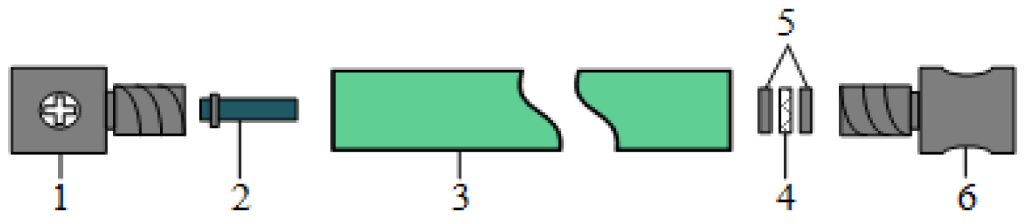
The structure of the carbon dioxide cracking pipe includes a charging valve, a heating element, a storage tube, a constant stress shearing sheet, seal rings, and a release hole. The cracking pipe’s structure is shown in Figure 2.
First, once the heating element was energized, it heated the liquid carbon dioxide stored in the storage tube, and the liquid carbon dioxide transformed to a supercritical state when it was affected by the heat. Following this, the pressure in the tube increased rapidly, and when the pressure exceeded the constant stress shearing sheet maximum shear strength, the constant stress shearing sheet broke. At this point, liquid carbon dioxide vaporized and swelled to more than 600 times its original volume, and the high-pressure gas formed in the storage tube was released outward from the release hole at a speed of several hundred meters per second, which formed a jet along a certain angle and direction. The jet acted on the borehole wall, causing it to break. The energy and direction of the liquid carbon dioxide phase transition was controlled by selecting storage tubes of different lengths and diameters, selecting a constant stress shearing sheet at different pressure levels, and setting the release hole at different angles. This process was highly secure because it did not ignite any gas and all heating processes were carried out in a sealed tube. The blasting hole structure of the phase transition is shown in Figure 3.
By comparing liquid carbon dioxide blasting with explosive blasting, we found that the high-pressure gas blasting has advantages of slower growth of pressure and longer time duration of high pressure. Furthermore, compared to hydraulic fracturing, it results in higher pressures after the high-pressure gas explosion. In conclusion, the high-pressure gas produced by the liquid carbon dioxide phase transition has a more direct effect on promoting cracks in coal. The action times and the pressures of different cracking techniques are shown in Figure 4 [17].
From the results of the application, we found that among the perforated blasting of the surface mine and quarry [18,19], blasting the coal and stratum generated clear transverse cracks along the hole direction, the steps and the blasting area did move significantly, and the vibration was small, which confirmed the above conclusion.
(2) Experimental content
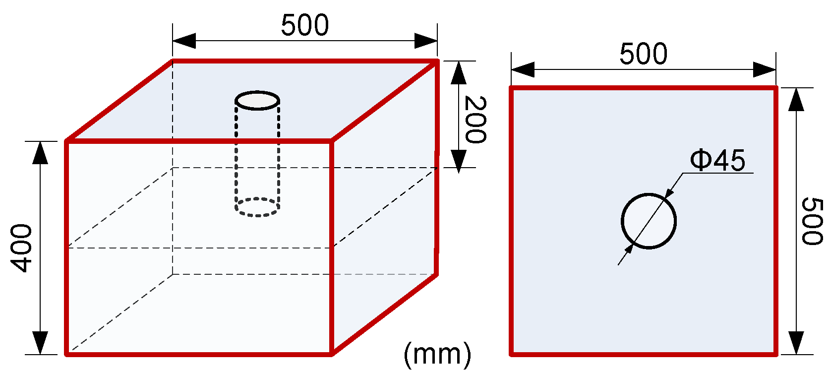
To further understand the failure characteristics of rocks under the action of the carbon dioxide phase transition and rocks breaking technology mechanism of liquid carbon dioxide phase transition, the liquid carbon dioxide phase transition breaking rock mass test was carried out under a free field. To reduce the influence of boundary effects on the test effect of liquid carbon dioxide, a large rock sample of size 500 mm × 500 mm × 400 mm was used in the test. The sample structure diagram is shown in Figure 5.
The test model was made by mixing concrete, with concrete at a 2:1:0.5 ratio of 425# Portland cement: Fine sand: Water. The matched model material was placed into a customized wooden model. To ensure uniformity and fewer bubbles, a small agitator was used to vibrate the material. After models were generated, samples were manually maintained for 28 days. The constant pressure shear sheet was rated to 70 MPa of pressure.
The main process of testing liquid carbon dioxide phase transition for breaking rock mass included filling, fixing, and blasting. In the experiment, the filled liquid carbon dioxide splitter was first put into the prefabricated blasting hole. A special iron frame was installed on the outside of the specimen to prevent flying rock during the experiment. The test equipment was fixed with a miniature forklift to prevent the equipment moving. The fixed carbon dioxide splitter was installed as shown in Figure 6.
The experiment was carried out four times. The test results and cracks distribution are shown in Figure 7.
According to experimental results, the following characteristics were observed:
- (1)
- Most of the test pieces were not broken to a high degree and were mostly of a large size. The surface of the borehole wall was unbroken and no crushing damage was found. After the failure of the specimen, no micro cracks developed on the surface, and the radius of the fracture zone was large.
- (2)
- Two main cracks, which were approximately in a linear distribution, were produced along the vertical release holes around the blasting hole, and ran through the whole experimental specimen. Each of the main cracks was long and narrow and produced few secondary cracks. There were few micro cracks on the circumferential wall of the blasting hole. Most of the cracks extended along the axial direction of the borehole. Whether a crack was a dominant main crack or an undeveloped micro crack, its normal direction was approximately perpendicular to the axial direction of the borehole. In summary, the cracking effect was good.
2.3. Extension Criteria for Initial Cracks with Initial Stress Field
The specimen is assumed to be subjected to a vertical stress of p, a horizontal stress of q, and p > q, and the direction of the release hole is assumed to be vertical. The stress on the radial line is calculated according to the Kirch formula [21], in which the angle between the stress and the horizontal axis is and the distance from the center of the borehole is r.
where is the normal stress at the calculated point; is the tangential stress at the calculated point. is the shearing stress at the calculated point.
The value of the radial stress and the tangential compressive stress of the rock on the wall can be obtained by including r = a in the formula above, when calculating the initial stress on the borehole wall.
Deriving the value of shows that when or 270, is at its minimum and as calculated by Formula (9), in the vertical direction, subjected to tensile stress derived from a pressure of . The initial stress on the borehole wall in the vertical direction can be calculated.
Since the borehole wall is generally subjected to tensile damage under the action of high-pressure carbon dioxide, the magnitude of the dynamic tensile strength of and the rock can be used to determine whether the rock is cracked. The force diagram of the borehole under confining pressure is shown in the following Figure 8.
It can be seen from the formula that the initial pressure on the borehole wall is related to the magnitude and direction of p and q. If the stress fields are different, initial cracks are generated in different directions. Using the formula, the initial tensile force on the borehole wall can be calculated, the initial tensile stress can be compared to the dynamic tensile strength of the rock, and the presence or absence of hole wall cracks can be determined.
3. Generation and Expansion of Cracks Under Stress Waves and High-Pressure Gas
Results of the liquid carbon dioxide phase transition rock breaking experiments confirmed the crack propagation characteristics without the initial stress field. However, the rock breaking mechanisms, such as the extension length of the crack under a certain pressure and the quasi-static effect of the high-pressure gas, have not been further explored. Therefore, it is necessary to study the role of the stress wave and the high-pressure gas generated by the liquid carbon dioxide phase transition in rock breaking.
3.1. The Generation and Expansion of Cracks Under Stress Waves
After the rapid phase transition of liquid carbon dioxide in the storage tube, the carbon dioxide quickly fills the borehole, and the oscillation impacts the wall of borehole. Under the impact pressure of the high-pressure gas, the medium around the release hole generates a compressive stress wave, which propagates outward in the form of a cylindrical wave. Because the peak value of the stress wave produced by the liquid carbon dioxide phase transition is small, the shock wave intensity may be less than the dynamic compressive strength of the rock that is undergoing action related to the phase transition process. At this time, the rock will not cause crushing damage; therefore, the formation process of the crushing zone is not discussed here. The stress wave generated by the liquid carbon dioxide phase transition spreads rapidly in rocks. When the strength of the stress wave is less than the dynamic compressive strength of rock mass itself, the stress wave is not enough to cause rock damage directly. However, the compressive stress wave will cause radial displacement of the rock mass, thus producing tensile stress in the rock. Under tensile stress, the rock will undergo tensile failure. A schematic diagram of the tensile stress wave tension of liquid carbon dioxide is shown in Figure 9.
The pressure of stress wave decreases exponentially with the increase in propagation distance [22,23]. This relationship is shown as follows:
where is the radius of the blasthole; R is the distance from a point to the center of the borehole; is the stress wave attenuation index, , where is the Poisson ratio of rock, .
In the process of stress wave propagation, the relationship between the tangential stress and the radial stress around the borehole can be expressed as follows [10]:
where b is the ratio of the transverse wave to the longitudinal wave velocity of rock, . Rock cracks occur when the tensile stress of rock mass exceeds the dynamic tensile strength of the rock mass; it can be expressed in the following formula:
where is the tensile strength of the rock; is the tensile strength increase coefficient of the rock at a dynamic load.
The radius of the fracture zone under the stress wave was calculated using Equations (12)–(14), and can be expressed by the following formula.
According the above formula, whether the rock at a distance of r from the center of the borehole has been tensile fractured under the action of stress waves generated by high-pressure carbon dioxide can be determined.
3.2. Mechanism Analysis of Crack Propagation Under High-Pressure Gas Quasi-Static Action
The stress wave generated by the liquid carbon phase transition has a short action time and a low peak value and creates few initial cracks. However, initial cracks play a guiding role in the action of high-pressure carbon dioxide, which controls the direction of crack propagation [24]. Subsequently, a large amount of high-pressure carbon dioxide produced by the liquid carbon dioxide phase transition suffuses the whole borehole, which generates a quasi-static stress field in the borehole. Continuous high-pressure gas acts on the cracks generated by stress waves, and the initial cracks are subjected to high-pressure stress loading, which causes the initial cracks in the borehole to evolve, break through, and secondarily expand. The quasi-static action mechanism of high-pressure carbon dioxide gas is analyzed as follows:
Under the action of stress waves, it is assumed that N initial cracks with an average radius of are generated along the borehole wall, with the center of the hole at the origin in polar coordinates, and the distribution pressure along cracks surface of the rock mass given by . The dynamic propagation model of planar wedge cracks under the quasi-static of high-pressure carbon dioxide gas can be obtained by using a two-dimensional axisymmetric plane strain mechanical model (Figure 10) to examine the blasting problem in infinite rock mass.
We make the assumption that in the process of changing borehole pressure, the escape of liquid carbon dioxide gas is not taken into account. Therefore, the total mass of the carbon dioxide is certain. In the process of crack growth, can be obtained according to the state equation of ideal gas law ().
The initial mode-I crack produced by the stress wave continues to crack under the action of the quasi-static stress field of high-pressure carbon dioxide. Therefore, the stress intensity factor at the crack tip is:
Since the pressure field of high-pressure carbon dioxide gas is a quasi-static process, the pressure of the whole borehole is . The stress field of the high-pressure carbon dioxide will lead to the development and evolution of initial cracks, which will continuously increase the volume of the borehole. In the meantime, the pressure inside the borehole drops gradually. According to the selected mathematical model, we can obtain the following formula:
where M is a constant; is the unit volume.
The initial crack is produced by the stress wave. According to the Formula (10), the radius of the crack is . Therefore M is calculated as follows:
where , is the rated pressure of constant pressure shears sheet, k is the correction factor, and is between 0–1.
Therefore:
By substituting Formula (20) into Formula (17), the stress intensity factor of the crack tip under quasi-static action can be obtained as follows:
Equation (21) is the relation expression between crack propagation radius and stress intensity factor. If the stress intensity factor of the crack tip is equal to or greater than the fracture toughness of the rock , then the initial crack generated by the stress wave begins to develop. According to the law, the maximum length of crack expansion can be obtained.
4. Conclusions
(1) The analysis of the cracking process of the liquid carbon dioxide phase transition shows that when the constant pressure shear sheet breaks, the high-pressure carbon dioxide flows out from the release hole rapidly, forming a high-pressure gas jet that acts on the borehole wall. The formula to calculate the initial impact pressure acting on the borehole wall was derived using the relevant formulas of liquid mechanics. The pressure of the liquid carbon dioxide in the liquid storage pipe can be increased appropriately to achieve a better effect on breaking the rock mass.
(2) Under different confining pressure conditions, the pattern of crack initiation is deduced when high-pressure gas acts on the borehole wall. It is ostensible that the magnitude of tensile stress on the borehole wall and dynamic tensile strength of rock can be used to determine whether initial cracks are caused. Following this, a carbon dioxide phase transition fracturing test without initial stress field was conducted. The results show that in the absence of initial stress field, the crack preferentially occurs in the wall of the vertical release hole, and the crack extends along the axial direction of borehole.
(3) The radius of the fracture zone caused by stress waves, which was generated by the liquid carbon dioxide phase transition, was calculated. Next, high-pressure gas acted on cracks caused by the stress wave. By using dynamic propagation model of planar wedge cracks, the expression of the stress intensity factor () with respect to the crack radius r under high-pressure gas acting was derived. Our study highlights that the developing of cracks can be judged by comparing the magnitude of stress intensity factor () and fracture toughness of rock. When the stress intensity factor () is equal to the fracture toughness of rock, maximum radius of cracks can be obtained by substituting the stress intensity factor () into the Formula (21).
Author Contributions
Conceptualization, F.G. and K.Z.; methodology, Y.Z. and B.K.; validation, F.G. and K.Z.; formula analysis, L.T.; resources, F.G. and K.Z.; data curation F.G. and L.T.; writing—original draft preparation, F.G. and L.T.; supervision K.Z. and B.K.; project administration F.G. and K.Z.
Funding
This work is supported by the Natural Science Foundation of China [Grant no. 51474252], the Postgraduate Research and Innovation Foundation of Central South University [2018zzts750] and the National Key Research and Development Program of China (2018YFC0808404).
Acknowledgments
Thanks to assistant editor Ivy Chang for your help during this time. Thanks to the recognition and valuable comments of the two experts. Thanks to Master Yu Songtao for his help in correcting the mistakes in grammar.
Conflicts of Interest
The authors declare no conflict of interest.
References
- Holm, L.W. Carbon dioxide solvent flooding for increased oil recovery. J. Petrol. Technol. 1959, 216, 225–231. [Google Scholar]
- Global, J. Cardox system brings benefits in the mining of large coal. Coal Int. Redhill 1995, 243, 27–28. [Google Scholar]
- Zhang, C.; Lin, B.Q.; Zhou, Y.; Cheng, Z.; Zhu, C.J. Study on “fracturing-sealing” integration technology based on high-energy gas fracturing in single seam with high gas and low air permeability. Int. J. Min. Sci. Technol. 2013, 23, 841–846. [Google Scholar] [CrossRef]
- Lu, T.K.; Wang, Z.F.; Yang, H.M.; Yuan, P.J.; Han, Y.B.; Sun, X.M. Improvement of coal seam gas drainage by under-panel cross-strata stimulation using highly pressurized gas. Int. J. Rock Mech. Min. Sci. 2015, 77, 300–312. [Google Scholar] [CrossRef]
- Tian, S.C.; He, Z.G.; Li, G.S.; Wang, H.Z.; Shen, Z.H.; Liu, Q.L. Influences of ambient pressure and nozzle-to-target distance on sc-co 2 jet impingement and perforation. J. Nat. Gas Sci. Eng. 2016, 29, 232–242. [Google Scholar] [CrossRef]
- Pal, K.; Rajasekar, R.; Kang, D.J.; Zhang, Z.X.; Pal, S.K.; Jin, K.K.; Das, C.K. Effect of fillers and nitrile blended pvc on natural rubber/high styrene rubber with nanosilica blends: Morphology and wear. Mater. Des. 2010, 31, 25–34. [Google Scholar] [CrossRef]
- Uhlmann, E.; Hollan, R. Blasting with solid carbon dioxide—Investigation of thermal and mechanical removal mechanisms. Procedia CIRP 2015, 26, 544–547. [Google Scholar] [CrossRef]
- Guo, Z.X. Liquid carbon dioxide blasting cylinder and on-site test explosion. Blasting 1994, 8, 72–74. [Google Scholar]
- Xu, Y.; Cheng, Y.S.; Wang, J.L. Foreign high pressure gas explosion. Coal Sci. Technol. 1997, 25, 52–53. [Google Scholar]
- Sun, K.M.; Xin, L.W.; Wang, T.T.; Wang, J.Y. Simulation research on law of coal fracture caused by supercritical CO2 explosion. J. China Univ. Min. Technol. 2017, 46, 501–506. [Google Scholar]
- Wang, Z.F.; Sun, X.M.; Lu, T.K.; Han, Y.B. Experiment research on strengthening gas drainage effect with fracturing technique by liquid co2 phase transition. J. Henan Polytech. Univ. (Nat. Sci.) 2015, 34, 1–5. [Google Scholar]
- Zhou, K.P.; Ke, B.; Li, J.L.; Zhang, Y.N.; Cheng, L. Pressure dynamic response and explosion energy of liquid carbon dioxide blasting system. Blasting 2017, 34, 7–13. [Google Scholar]
- Huang, L.G.; Zhang, F.L.; Zhang, Z.; Cheng, K. Study on application of CO2 fracturing apparatus in pre-splitting blasting of rock deep hole. Blasting 2017, 34, 131–135. [Google Scholar]
- Zhou, X.H.; Men, J.L.; Song, D.P.; Li, C.Y. Research on optimal borehole parameters of antireflection in coal seam by liquid CO2 blasting. Chin. J. Rock Mech. Eng. 2016, 35, 524–529. [Google Scholar]
- Wang, H.Z.; Li, G.S.; He, Z.G.; Shen, Z.H.; Wang, M.; Wang, Y.W. Mechanism study on rock breaking with supercritical carbon dioxide jet. Atomization Sprays 2017, 27, 383–394. [Google Scholar] [CrossRef]
- Wang, R.H.; Huo, H.J.; Huang, Z.Y.; Song, H.F.; Ni, G.J. Experimental and numerical simulations of bottom hole temperature and pressure distributions of supercritical CO2 jet for well-drilling. J. Hydrodyn. 2014, 26, 226–233. [Google Scholar] [CrossRef]
- Hu, J.H. Non-explosive blasting technology symposium held in Beijing. Eng. Blast. 2016, 22, 89. [Google Scholar]
- Wang, G.B.; Peng, J.Y.; Xu, Z.Y. Application of carbon dioxide fracturing for blasting technology in buzhaoba open-pit mine. Opencast Min. Technol. 2017, 32, 40–42. [Google Scholar]
- Wang, J.; Xiao, Y.S. Marble stone is mined in a limestone mine based on carbon dioxide blasting technology. Mod. Min. 2015, 554, 15–17. [Google Scholar]
- Zhang, Y.N.; Deng, J.R.; Deng, H.W.; Ke, B. Peridynamics simulation of rock fracturing under liquid carbon dioxide blasting. Int. J. Damage Mech. 2018. accept. [Google Scholar]
- Wang, W.X. Rockmass Mechanics, 1st ed.; Central South University: Changsha, China, 2004. [Google Scholar]
- Xu, Y. Development of high pressure gas blasting coal mining technology and its application in China. Blasting 1998, 15, 67–69. [Google Scholar]
- Zhan, D.S.; Huang, L.G.; Qiu, T.D. Study on mechanism and experiment of high pressure carbon dioxide blasting and permeability improved technology. Mine Constr. Technol. 2016, 37, 31–34. [Google Scholar]
- Yao, J.J. Damage rock blasting parameter calculate based on blasting fissure fractal dimensions. Chin. J. Solid Mech. 2008, 29, 95–98. [Google Scholar]
Figure 1.
Diagram of initial crack propagation on the borehole wall without confining pressure.

Figure 2.
Cross-sectional diagram of cracking pipe: (1) charging valve; (2) heating element; (3) storage tube; (4) constant stress shearing sheet; (5) seal rings; (6) release hole.
Figure 2.
Cross-sectional diagram of cracking pipe: (1) charging valve; (2) heating element; (3) storage tube; (4) constant stress shearing sheet; (5) seal rings; (6) release hole.

Figure 3.
Schematic diagram of the borehole when the cracker is placed.

Figure 4.
Pressure curve diagram of explosive blasting, liquid carbon dioxide blasting, and hydraulic.
Figure 4.
Pressure curve diagram of explosive blasting, liquid carbon dioxide blasting, and hydraulic.

Figure 5.
Size diagram of concrete sample.

Figure 6.
Fixed carbon dioxide splitter.

Figure 7.
Concrete specimen failure state and cracks distribution after the experiment [20]: (a) Failure state and cracks distribution of D1 specimen; (b) Failure state and cracks distribution of D2 specimen; (c) Failure state and cracks distribution of D3 specimen; (d) Failure state and cracks distribution of D4 specimen

Figure 8.
Diagram of initial crack propagation under confining pressure.

Figure 9.
Schematic diagram of tensile failure of rock under stress wave action.

Figure 10.
Dynamic propagation model of planar wedge cracks in infinite rock mass.

© 2018 by the authors. Licensee MDPI, Basel, Switzerland. This article is an open access article distributed under the terms and conditions of the Creative Commons Attribution (CC BY) license (http://creativecommons.org/licenses/by/4.0/).
Share and Cite
MDPI and ACS Style
Gao, F.; Tang, L.; Zhou, K.; Zhang, Y.; Ke, B. Mechanism Analysis of Liquid Carbon Dioxide Phase Transition for Fracturing Rock Masses. Energies 2018, 11, 2909. https://doi.org/10.3390/en11112909
AMA Style
Gao F, Tang L, Zhou K, Zhang Y, Ke B. Mechanism Analysis of Liquid Carbon Dioxide Phase Transition for Fracturing Rock Masses. Energies. 2018; 11(11):2909. https://doi.org/10.3390/en11112909
Chicago/Turabian StyleGao, Feng, Leihu Tang, Keping Zhou, Yanan Zhang, and Bo Ke. 2018. "Mechanism Analysis of Liquid Carbon Dioxide Phase Transition for Fracturing Rock Masses" Energies 11, no. 11: 2909. https://doi.org/10.3390/en11112909
Note that from the first issue of 2016, this journal uses article numbers instead of page numbers. See further details here.