Solid Fuel Production from Semi-Natural Grassland Biomass—Results from a Commercial-Scale IFBB Plant


1
Grassland Science and Renewable Plant Resources, Universität Kassel, Steinstrasse 19, 37213 Witzenhausen, Germany
2
Abfallswirtschaftsgesellschaft des Rems-Murr-Kreises, 71332 Waiblingen, Germany
*
Author to whom correspondence should be addressed.
Energies 2018, 11(11), 3011; https://doi.org/10.3390/en11113011
Submission received: 24 August 2018
/
Revised: 21 September 2018
/
Accepted: 24 October 2018
/
Published: 1 November 2018
(This article belongs to the Special Issue Energy Conversion of Rural and Urban Residual Biomass)
Abstract
:Biomass-based energy accounts for a notable share of renewable heat and electricity generation in Germany. Due to limited alternative uses, biomass obtained from management of semi-natural grasslands is a potential feedstock. Technical and environmental limitations exist in using this biomass for combustion, due to the presence of harmful elements. Converting biomass using integrated generation of solid fuel and biogas from biomass system (IFBB) produces a solid fuel with lower concentrations of harmful elements and a press liquid usable for biogas generation. In this study, solid fuel generation with a commercial scale IFBB unit was investigated. The concentration of harmful elements such as N, S, Cl, and K in the solid fuel was significantly reduced compared to the original biomass silage. Emissions during combustion of the solid fuel briquettes were below German legal thresholds. Elemental concentration of solid fuel obtained from commercial scale process had a significant improvement in removal rate of harmful elements than the prototype. Hence, the limitations of using semi-natural grassland biomass as an energy source were overcome. The commercial scale IFBB plant could be used in practice to handle large volumes of green residual biomass by converting it into a solid fuel with favorable fuel properties.
1. Introduction
The energy transition “Energiewende” in Germany aims to mitigate climate change by replacing fossil fuels and to realize a stable energy supply that is both economically feasible and environmentally friendly [1]. Bioenergy involves mainly biogenic solid fuel (e.g., firewood), biogenic liquid fuel (e.g., ethanol) and biogas, which account for 27% and 86% of renewable based electricity and heat generation, respectively [2]. While politics focused on only electricity in the recent years, generation of renewable heat is now increasingly supported. Mitigation of climate change is less effective when land-intensive bioenergy feedstocks are used, leading to detrimental climate effects and negative impacts on the ecosystem and biodiversity [3]. Further, the increasing demand for land for non-food purposes in the present scenario where food and feed demand are expected to increase, could be a threat to food security [4]. Enlarging the biomass base with residual biomass and strictly cascading the use of biomass can help in reducing the competition with land for food [5]. Therefore, potential biomass sources for bioenergy in the future should minimize conflict with food and feed production and have low negative impacts on the environment, i.e., water bodies, atmosphere, and biodiversity [6].
In the early half of the 20th century, low-intensity land use had led to species rich and biodiverse grassland areas in Europe, but in the latter half of the century, biodiverse but unproductive habitats and their associated species rapidly declined as a result of intensification and abandonment [7]. The change of support mechanisms and other economic pressures had led to abandonment, resulting in the build-up of mature and senescent plant material with high fiber content and low nutritional value due to the lack of management [8]. In addition to maintaining biodiversity, semi-natural grasslands contribute to the ecosystem by carbon sequestration, regulating soil erosion and water flow [9]. Hence, maintaining semi-natural grasslands using proper management techniques is necessary [10]. Large quantities of grassland biomass that is generated as a result of management across Europe and in other parts of the world are often underutilized [11] or even regarded as waste and left on the field to decompose [12].
Alternatively, grassland biomass can be utilized as a feedstock for energy generation [13,14,15] through combustion [10] or anaerobic digestion [16]. But, in its original form, biomass from semi-natural grassland is neither a favorable substrate for anaerobic digestion because of the low methane yield due to its lignin content [17,18], nor is it a suitable solid fuel for combustion due to environmental, technical, and logistical issues [19]. The presence of harmful elements such as nitrogen (N), sulphur (S), and chlorine (Cl) in grassland biomass, has an influence on emissions [20] and also affects ash melting behavior due to potassium (K), sodium (Na), and magnesium (Mg) contents [21]. The concentration of N in fuel has a direct influence on the NOx emissions [22] and S plays a role in the formation of SO2 [23]. Furthermore, S also influences corrosion processes in boilers. Cl affects the metal components in the furnace and boiler due to corrosion through chloride salts and HCl formed during combustion [24]. Cl along with K results in severe ash slagging, fouling, and high-temperature corrosion [25].
The integrated generation of solid fuel and biogas from biomass (IFBB) process aims to improve the fuel quality of semi-natural grassland biomass by removing significant amounts of elements which are detrimental to combustion [26]. This process consists of mixing the ensiled grassland biomass with water at a defined temperature for a defined period of time. The resulting mash is then mechanically separated into a solid fuel that is used for combustion and a press liquid that is used for anaerobic digestion [18,27]. The solid fuel thus obtained was shown to have a lower concentration of elements such as K, Cl, N, and Mg [26,28]. The potential of the IFBB technique to provide a solid fuel with improved fuel quality for combustion and a press fluid to be used for anaerobic digestion from European grassland biomass has so far been studied on a laboratory scale and a prototype IFBB unit by references [28,29], respectively. In both cases the solid fuel produced had low elemental concentration of unwanted elements and ash softening temperatures were higher in the solid fuel compared to the silage [30]. The press fluid obtained was found to be a suitable substrate with high biogas yield [29] due to a higher concentration of readily digestible crude protein and lower concentration of less digestible fiber [18]. The conversion of biomass into solid fuel and press fluid using IFBB had an energy conversion efficiency between 44.7% and 52.9% depending on the system, compared to 16.9% for anaerobic digestion of the untreated biomass [31].
The successful implementation of the IFBB process on a laboratory and prototype scale unit leads to the question of how the upscaling to a commercial scale IFBB unit would influence the results in terms of concentration of elements and ash melting behavior of the solid fuels and the resulting emissions during combustion.
The commercial-scale IFBB unit used for this study was established 2012 in the city of Baden-Baden and is the first commercial scale plant of its kind. Typical semi-natural grassland biomasses were collected from 11 different areas across Europe within the interregional EU projects COMBINE [32] and DANUBENERGY [33] and tested at the plant.
The present study analyzes
- (i)
- energetic and chemical fuel properties of the fuels produced using the commercial scale IFBB process, especially focusing on the reduction of detrimental mineral elements from silage to solid fuel.
- (ii)
- the combustion performance and emission characteristics of the fuels.
- (iii)
- the ash melting behavior of the silage and the fuels produced.
To gain insight into upscaling effects related to the IFBB procedure, fuel data from the commercial scale were compared with those from the prototype scale.
2. Materials and Methods
2.1. Commercial Scale Plant
The commercial-scale IFBB unit used for this study is capable of handling 12,000 tons of fresh biomass per year which consists, among others, mainly of green cut, wood, brushwood, grass, and tree leaves. This unit is part of the municipal sewage plant of the Baden-Baden city Environment Technique in south-west Germany, the plant has a capacity of 200,000 population equivalents. The presence of green areas and forests, in and around the city leads to the high availability of biomass feedstock. In addition to this, the biomass from various nature conservation areas is also handled at this facility. In the past, biomass that arrived at the facility was composted but this was no longer feasible as the costs of producing a high-quality compost were rising, whereas the demand for compost did not. Hence, the IFBB process was implemented on a large scale to convert the biomass into a solid fuel that is either combusted on-site or compacted into briquettes for storage and transport before combustion. The press fluid obtained is fed into the hydrolysis stage of a biogas plant to produce biogas for heat and electricity generation. The solid fuel and briquettes produced had a density of 600 kg·m−3 and 1000 kg·m−3, respectively. In Baden-Baden, the loose solid fuel is combusted in a biomass boiler (ALA-TALKKARI-Veto 500) with a capacity of 2 × 420 kW. The heat produced is used for internal needs of the plant, such as heating of digesters and buildings and drying of press cake and wood chips.
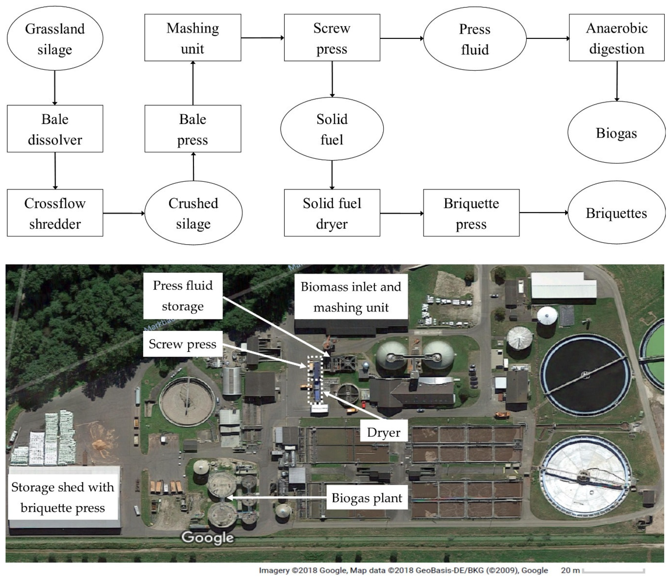
Test material from the different regions was delivered to the Baden-Baden facility in silage bales weighing approximately 500 kg. The operational flow of the process to produce solid fuel from biomass at the Baden-Baden unit is depicted in (Figure 1). Upon reception, the silage bales were inserted into a bale dissolving unit (Arjes-VZ 750D, Germany) to loosen the compacted silage. The silage was then passed through a 90-kW cross flow shredder (MEBA-UNI-CUT®Bio-QZ 1200, Germany) that crushed the silage using rotating metal chains to obtain a homogeneous short fiber length, which was required to process the silage in forthcoming steps. Then, the crushed silage was compacted by a bale press and enwrapped with foil. With the help of a band conveyor, the silage was transported into a 25 m3 mashing tank for hydrothermal conditioning. The hydrothermal conditioning process involved the mixing of silage with cleaned water from the sewage plant for 40 min. Even though higher mashing temperature aids in better removal of unwanted elements from the press cake [26], the mashing was done using tap water at 10 °C. Heating was not possible due to the high energy demand to warm the large quantity of water used for the commercial scale process. The quantity of water used was proportional to the dry matter (DM) content of the silage, to achieve a fluidic mash with a DM content of approximately 3–5% that could be easily pumped. The mash was then passed through a 60-kW screw press (FAN SEPARATOR, Germany), the resulting press fluid was directed to a 2000 m³ anaerobic digester and the solid fuel obtained was transferred into a band dryer (NEW eco-tec). The dried solid fuel which contained around 90% DM was compacted into briquettes using a 50-kW briquette press (Mütek-MAP 750, Germany).
2.2. Grassland Biomass
Botanical determination was conducted on three random study areas of 5 m × 5 m which were established at each of the 11 grassland sites. Vegetation was mostly dominated by grasses and sedges but with distinct differences in the botanical composition (Table 1, for botanical details see Table A1). The test material included grassland silages from Belgium, roadside maintenance cuttings from France, and wetland vegetation from Wales. Further silages originated from typical floodplain areas across Central Europe (Table 1). Green cut and grassland biomass that was deposited at the Baden-Baden municipal plant was also included for the comparison between prototype and commercial-scale plant. As this sample was a mix of various residual biomass from the Baden-Baden region, data on the composition of vegetation was not available.
2.3. Chemical Analysis and Heating Value
Silage samples for the chemical analysis were taken after opening and chopping the silage bales, the press cake samples were taken after mashing, pressing, and drying. Eight silage and 8 press cake samples from the DANUBENERGY project, 3 silage and 3 press cake samples from the COMBINE project, and 1 silage and 1 press cake sample from Baden-Baden were taken to be tested, with 3 replicates of each sample amounting to a total of 36 silage and 36 press cake samples which were used for this study. The analysis of mineral content in the silage and solid fuel was carried out using X-ray fluorescence spectroscopy by an accredited external laboratory. Carbon (C), Hydrogen (H), and N content in samples were measured using 150 mg of dried material in an elemental analyzer (Vario MAX CHN Elementar Analysensysteme GmbH, Hanau, Germany). Using data from the above analysis, the higher heating value (HHV) was calculated using the following equation [34].
HHV (MJ·kg−1 ) = 3.55C2 − 232C − 2230H + 51.2C × H + 131N + 20600
The lower heating value (LHV) was calculated from HHV by deducting the latent heat of vaporization, where 8.937 is the mass share of hydrogen in a water molecule and 2.2 is the enthalpy of water vaporization, C, H, and N are carbon, hydrogen, and nitrogen in the press cake expressed in %DM.
LHV (MJ·kg−1 ) = HHV − (8.937 × H/100) × 2.2
Corrosion index (2S/Cl) was used to identify the risk of corrosion and was calculated according to reference [22]
2.4. Combustion and Ash Melting Test
Combustion tests were carried out with the solid fuels AC, AE, AM, CD, DC, and PA2 in the form of compacted briquettes. The tests were conducted on a test bench with an ÖKOTHERM—compact plant C1L (ÖKOTHERM, Germany) with a nominal output of 120 kW in accordance with the DIN EN304 [35] criteria. The boiler output was adjusted continuously between 30–100% of the nominal load. For each fuel type, the tests were carried out in three phases; heat-up phase, partial load (50% nominal output), and full load (100% nominal output). The heating system is stoker-fired and has a cooled combustion cavity; automated lambda control was also included. The experimental procedure was carried out in accordance with DIN EN 303-5 [36]. The gas and particulate matter (PM) emissions were tested using a standardized emission test section installed in the exhaust line. The levels of O2, CO2, CO, NOx, and SO2 in the exhaust were detected using an ecom-J2KNpro (Ecom, Germany) compact analyzer. The amount of fuel used was determined by weighing hourly over the test period, the power and efficiency were calculated in accordance with DIN EN 0304 + A.7 A.8 [35]. The removal of ash was carried out by an ash pusher into a collection tray.
For the ash melting test, 30 g of biomass was ground with a cutting mill and incinerated in a muffle furnace at 550 °C. The material was annealed for 1 h at 700 °C for full incineration; the ashes produced were compacted into a cylindrical form of 3 mm diameter and 3 mm height. The ash melting behavior was tested using a hot stage microscope (Hesse Instruments, Germany) connected to a CCD camera. Automatic contour recognition and evaluation of the silhouettes were used to identify characteristic temperatures at softening, spherical, hemispherical, and flowing point of the ashes according to DIN 51730 [37], ISO 540 [38], CEN/TS 15404 [39], and CEN/TS 15370-1 [40]. The temperature inside the microscope was increased at a rate of 10 K·min−1 and images were captured every minute. When the software had difficulties in identifying the form, manual identification was used. In some cases, the form could not be determined neither automatically nor manually; this difficulty mainly occurred for the spherical and hemispherical stage.
2.5. Prototype Plant
For the comparison of commercial (Figure 1) and prototype (Figure 2) plants, data on elemental reduction originates from reference [28] and data on ash melting behavior was provided by reference [30]. Data for the above studies involved grassland biomass samples from a total of 18 sites in Estonia, Germany, and the United Kingdom. The conversion of biomass samples to solid fuel was done in a prototype scale IFBB unit which could handle 300 kg per day (for details see [28]). Unlike the commercial scale unit, the silage to water ratio during the mashing stage was held constant at 1:8 and the mashing time was 30 min with a water temperature of 25 °C. The process parameters are summarized in (Table 2), the parameters given below show the variation in operating conditions for the prototype and commercial scale.
2.6. Statistical Analysis
Statistical analysis was carried out using R software package [41]. The datasets were checked for normal distribution using the Shapiro–Wilk normality test and were verified visually. Since most of the datasets were not normally distributed, differences between the silage and solid fuel in terms of elemental concentration and ash melting temperatures were tested using Wilcoxon rank sum test, which was also used for comparisons between prototype and commercial scale units. Effects of silage and press cake chemistry on the ash softening and flowing temperature were tested using multiple linear regression modelling with interactions, considering the principles of hierarchy and marginality in the development of models [42].
3. Results
3.1. Elemental Concentrations
A significant reduction in the elemental concentration caused by dewatering of silage was observed for almost all elements, except for Na (Table 3). The rate of reduction varied from 24.73% for Ca to 89.42% for Cl. The mean reduction of Cl was in the range of removal rate of Cl from biomass after washing and mechanical separation confirmed by similar studies [43]. K and S was reduced by 88% and 62%, respectively, in this study, which were above the reduction rates of 84% and 55% observed by reference [43]. According to reference [44], there would be a corrosion risk by Cl only if the concentration is above 0.1 %DM. Most of the solid fuel samples had a Cl concentration below this threshold. During combustion, S present in the biomass fuel forms alkali sulphates and gaseous SOx. Due to cooling of flue gas in the boiler, these sulphates condense at the heat exchanger. The concentration of S in the solid fuel was lower than 0.09% DM, which was slightly below the guiding value for unproblematic combustion of 0.1% DM [20]. A perception of the actual high temperature corrosion risk can be obtained by using the molar 2S/Cl ratio [22].
A ratio above 4 would indicate a minor risk and above 8 would indicate negligible risk. The 2S/Cl ratio for the solid fuel samples had an average of 3.27 ± 1.18 compared to silage values of 0.92 ± 0.40. So, the corrosion risk was comparatively lower for the press cake, but the data still indicate a minor corrosion risk. A much higher 2S/Cl ratio of 11.9 was reported for mechanically leached solid fuel from grass by reference [43], which can be explained by the lower removal rate of Cl and the higher removal rate of S in the Baden-Baden plant.
Considering the factors influencing the removal rate, previous studies showed that the removal of Cl from silage was better at lower hydrothermal conditioning temperatures [26,27]. This contrasted with the influence of temperature on the removal of other soluble elements. The improved removal of Cl at lower temperatures may be explained by the dissolution of a majority of Cl in the form of Cl− at lower temperatures and by the competition among other ions for entry into water [45]. Moreover, studies have suggested that hydrothermal conditioning temperature has a negligible effect on removal rates of soluble elements from grass silage [46] and that the effect of temperature varies with the type of biomass [45]. The silage samples had DM contents between 26.55% and 83.56%, higher DM content resulted in more water being used during the mashing process. Dry matter content and the initial concentration of elements in silage could have an influence on the reduction rate of the respective elements, this influence was reported for Cl by reference [47].
In contrast to other elements, the concentration of Na during dewatering of silage increased in some of the samples. A similar increase in Na during treatment of biomass by washing was reported by reference [48]. Externally introduced Na from the water used for hydrothermal conditioning may be a reason for this. The mean ash content in the solid fuel was 3.97 ± 0.43% DM with a reduction of 51% from the silage. Despite the ash content being relatively lower than in other herbaceous fuels, the reduction rate was in the range reported by reference [43].
3.2. Ash Melting
As the elements affecting ash melting temperatures in biomass fuels are water-soluble [49], hydrothermal conditioning and mechanical separation were expected to increase the ash melting temperature from silage to solid fuel. Ash softening temperature (AST) in the solid fuel varied from 1050 °C to 1370 °C (Table 4) and the mean values were in the range of lignite and higher than for most of the herbaceous biomass fuels [49]. It was found that AST was mainly influenced by K and Ca, the former had a negative influence [30], which was also observed (R2 = 0.23) in this study. Ca had a positive influence (R2 = 0.33) on AST for silage, whereas in the case of solid fuel the influence was not significant. The increase in AST from silage to solid fuel was not significant even though there was a mean increase of 63 °C. This is in line with observations by reference [50] who found an increase of 12 °C, which was also not a significant increase.
A similar trend was observed for ash flowing temperature (AFT). A correlation between the AST and AFT was observed for solid fuel (R2 = 0.40), which, according to reference [49], implies that the major processes responsible for the ash melting behavior are similar. The silage ash showed a much weaker correlation (R2 = 0.11) between AST and AFT.
3.3. Combustion and Emission
Mean lower heating value increased by 0.43 MJ kg−1 (2.5%) due to dewatering of silage, which is less than the increase found by reference [43] (10%) and [51] (5%). Ash content in the fuel has a negative correlation to the heating value [52] and the strength of this relation depends on the type of biomass used, varying from R2 = 0.45 in rice straw to R2 = 0.88 in wheat straw [53]. A negative relation between heating value and ash content was also found in the present study, but it was not strong (R2= 0.53). In the combustion tests, all briquetted fuels ignited easily with the hot air automatic ignition and a full flame in the combustion chamber could be observed within 15 min. Due to destabilization of pressed fibers in the briquettes during transportation, some flying sparks could be observed. However, the sparks had no influence on the dust content in the flue gas, as they burned in the upper part of the boiler. Flying sparks were relatively lower in the partial load operation than in the full load, because of the lower air velocity from the blower.
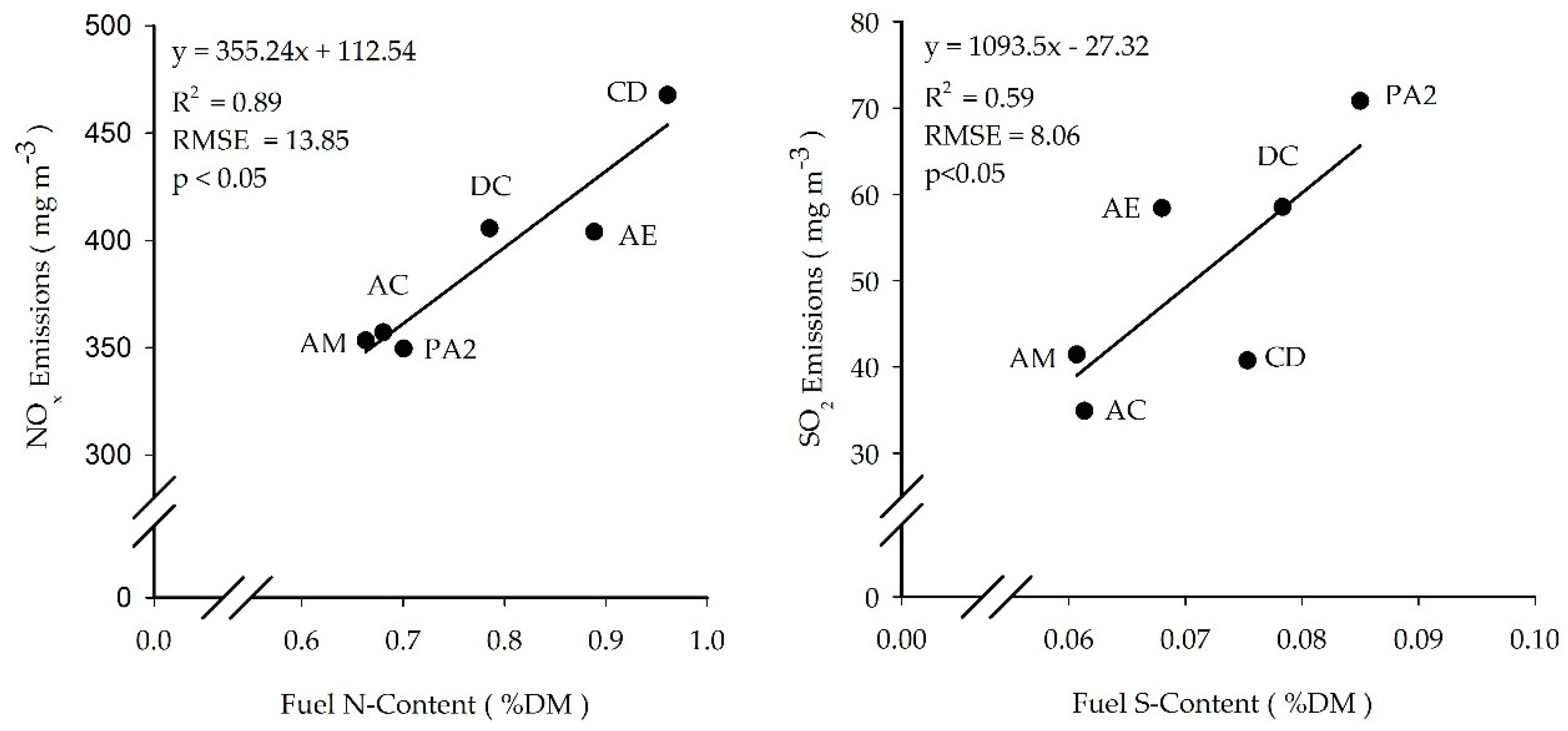
Due to the presence of higher N content in grassland biomass fuels (0.4 to 3.6% DM) [21], compared to solid fuels from other biomass sources, such as wood chips (0.1 to 0.9% DM) or bark (0.1 to 0.5% DM) [21], the NOx emissions tend to be higher [54]. A positive linear relationship between the fuel N content and the NOx emission was observed (R2 = 0.89) (Figure 3), implying that the reduction in N content in the solid fuel with the IFBB process (42 ± 10%) reduced the potential for NOx emissions. In all cases, NOx emissions at full load were below the threshold of 500 mg m−3 flue gas [55]. The higher values of emissions during partial load combustion can be attributed to the incomplete burn-off in the combustion zone. The quality of combustion could be indicated by the amount of CO emitted, with a lower emission indicating a higher conversion of C into CO2, resulting in complete combustion [21]. CO emissions at full load were highest at λ between 1.5 and 1.6 and decreasing gradually with increasing values of λ, similar to the findings of reference [56] for Miscanthus. CD was an exception, as it had highest CO emission at λ between 2.5 and 3. This information is particularly relevant for combustion chambers without automated λ control systems. Although SO2 emission was influenced by fuel S content, fuel S is not completely converted into SO2. A fraction of S remains in the ash and some is emitted as salts at lower temperatures [21]. Lower SO2 emission was observed with partial load due to a lower operating temperature. Even though the IFBB process reduced the ash content in the press cake, PM was higher in some cases (Table 5). PM in the flue gas is a result of incomplete combustion and, hence, is in most cases higher with partial load than with full load combustion. The use of electrostatic precipitators [43] and dust filters, which is common nowadays, can further reduce PM [57]. Hence, the IFBB solid fuel can be considered an appropriate fuel for industrial application.
Analysis of greenhouse gas (GHG) emissions generated during the production and use of semi-natural grassland fuels with IFBB technology was not covered in this study. However, it has been found that there is GHG savings of almost 3 t CO2-eq ha−1 for the prototype scale and a saving of almost 44 GJ ha−1 through the substitution of fossil fuel-based energy [31]. The GHG emissions can be attributed mainly to the heat, electricity, and fuel input during both the field operations and the IFBB process steps.
3.4. Comparison between Commercial-Scale Plant and Prototype
In the commercial scale IFBB process (CS), most harmful elements were reduced to a greater extent than in the prototype scale process (PT) (Figure 4). For example, the overall ash reduction was 51.6% in CS compared to 30.2% in PT. Even though Cl concentrations in the press cakes were similar for both CS and PT, the reduction rate of Cl in CS was higher (89.4%) than in PT (81.1%). K was reduced by 88.5% in CS compared to 73.7% in PT and S was reduced by 62.3% in CS, which is a significantly (p < 0.001) higher reduction compared to 34.55% in PT. More than 90% of the elements Cl and K in biomass are present in the form of water-soluble free ions (Cl−, KNO3, and KCl, respectively) [58]. The improved reduction rate in CS may be explained by the higher quantity of water used and extended retention time in the mashing stage, and by the different mashing technique itself (mixing in water in CS compared to sprinkling with water on a conveyor belt in PT). The concentration of N in the fuel was reduced by 42.2% in CS compared to only 17.5% in PT. Substantial parts of N contained in herbaceous biomass can be presumed to be firmly bound in the cell wall proteins, which is not easily mobilizable with the IFBB procedure [26]. Due to lower N concentrations in the fuel the combustion of solid fuel from CS can be expected to generate lower NOx emissions compared to other herbaceous biomass. The difference in mean concentration of P in CS and PT solid fuel was low, but the reduction rate was higher for CS at 72.2% compared to 58.2% for PT. Concentrations of Ca in solid fuels were similar, as were the reduction rates both for CS and PT. The presence of Ca in the solid fuel during combustion has a positive influence on the ash melting temperature [21], hence, the moderately lower reduction of Ca compared to other elements is favorable for solid fuel production. In terms of element reduction, the commercial-scale is a clear improvement compared to the prototype scale, regardless of the variation in biomass being used.
Ash softening temperature of solid fuel in CS was 1163 °C compared to 1050 °C in PT, which cannot be fully attributed to scaling effects, as AST in CS silage was also higher. The improvement in AST between silage and solid fuel for both CS and PT were similar (10%) and for AFT the trend was similar, with 1335 °C for CS and 1290 °C for PT, but the rate of increase in both cases was only 3%. While element concentrations in the silages were very variable, the variation in the solid fuel was much smaller, proving the ability of a commercial-scale IFBB plant to convert a very heterogeneous biomass into a more homogeneous fuel. Nowadays, renewable energy sources such as wind and solar face the challenge of balancing energy demand with weather dependent fluctuation of energy production, therefore flexible power generation sources that are less dependent on weather can be used to cope up with the electricity demand. Biogas can be used for flexible power generation where the electricity generation can be managed to meet the electricity demand, especially if an easily digestible substrate such as the IFBB press liquid is used for biogas production [59,60].
4. Conclusions
Combusting green and leafy grassland biomass is not feasible due to the presence of harmful elements (mainly minerals and N) and their effect on fuel properties, combustion process, and emissions. The presented results from an up-scaled IFBB process confirmed recent research on a laboratory and prototype scale: concentration of detrimental constituents in fuels were drastically reduced compared to the parent material and ash melting behavior was improved in comparison to silage. Emissions during combustion were within the stipulated thresholds, except for PM, which is of no concern, as efficient filtering systems are common standard. The practical implementation will be facilitated, as the fuels produced are compatible with standard biomass or wood-chip boilers.
Solid fuels, being a flexible power source that can be easily stored, may be a vital component of a future renewable energy system that can help mitigate the fluctuations caused by natural restrictions while generating power using solar and wind, especially in remote locations where other energy generation options are difficult.
Therefore, using green residual biomass from grasslands and landscape management with the IFBB technology generates an energy carrier which (i) does not conflict with other biomass uses, (ii) mitigates CO2 emissions, and (iii) helps to preserve landscape diversity.
Author Contributions
Conceptualization was done by M.W. and L.B., Data collection was done by L.B. and data analysis was done by B.J. and F.H. The manuscript was prepared by B.J.; M.W. and F.H. supervised the work.
Funding
We would like to thank the EU for financing the COMBINE project (No. 299J) and DANUBENERGY project (No. 4CE561P3) through the Interreg IV B regional development fund.
Acknowledgments
We are grateful to Bernhard Schäfer, manager of the Umweltbetrieb Baden-Baden, who provided the opportunity for measurements on the plant, as well as to the company ÖKOTHERM® for conducting the combustion tests.
Conflicts of Interest
The authors declare no conflict of interest.
Appendix A

Table A1.
Detailed botanical parameters of the samples including the dominant species, species coverage and species number for each region.
Table A1.
Detailed botanical parameters of the samples including the dominant species, species coverage and species number for each region.
| Species Coverage (%) | Species Number | ||||||||||||
|---|---|---|---|---|---|---|---|---|---|---|---|---|---|
| Species | DM (% FM) | FM (t·ha−1) | G | S/R | L | H | T | G | S/R | L | H | T | |
| AC | Agrostis capillaris, Holcus lanatus, Achillea millefolium | 28.50 | 20.33 | 109.50 | 2.67 | 14.33 | 107.17 | 233.67 | 11 | 2 | 6 | 32 | 51 |
| AE | Alopecurus pratensis, Arrhenatherum elatius, Holcus lanatus | 28.29 | 6.19 | 105.33 | 0.00 | 3.67 | 20.97 | 129.97 | 5 | 0 | 2 | 12 | 19 |
| AM | Agrostis x murbeckii, Holcus lanatus, Anthoxanthum odoratum, Galium spec. | - | - | 80.07 | 0.00 | 0.02 | 49.03 | 129.10 | 9 | 0 | 1 | 17 | 27 |
| AS | Agrostis stolonifera, Phragmites australis, Bolboschoenus maritimus | 51.33 | 16.93 | 68.07 | 21.53 | 0.07 | 18.20 | 107.87 | 4 | 9 | 1 | 8 | 22 |
| BS | Bromus erectus, Medicago falcata, Centaurea scabiosa | 24.85 | 11.00 | 22.87 | 1.87 | 51.40 | 40.07 | 116.20 | 11 | 2 | 12 | 26 | 51 |
| CD | Carex disticha, Phragmites australis, Holcus lanatus | 36.00 | 8.84 | 20.00 | 85.33 | 4.73 | 12.73 | 122.80 | 7 | 3 | 3 | 11 | 24 |
| DC | Deschampsia cespitosa, D. flexuosa, D. flexuosa, Carex leponina, Juncus acutiflorus | 49.00 | 5.23 | 75.80 | 79.87 | 37.00 | 26.80 | 219.47 | 6 | 6 | 2 | 8 | 22 |
| JE | Juncus effuses, Carex species, Alisma Plantago-aquatica | 32.50 | 16.23 | 3.23 | 75.33 | 0.00 | 35.93 | 114.50 | 3 | 5 | 0 | 9 | 17 |
| PA1 | Phalaris arundinacea, Urtica dioica | - | - | 84.33 | 0.67 | 0.00 | 24.00 | 105.00 | 3 | 2 | 0 | 3 | 8 |
| PA2 | Phalaris arundinacea, Carex acutiformis, Carex gracilis | 41.49 | 26.40 | 41.53 | 48.00 | 1.33 | 13.20 | 104.07 | 10 | 12 | 2 | 16 | 40 |
| PS | Phragmites australis, Phalaris arundinacea, Typha latifolia | 39.18 | 30.67 | 51.67 | 61.00 | 0.00 | 9.00 | 121.67 | 3 | 3 | 0 | 6 | 12 |
G—grasses, Sedges/Rushes—S/R, L—Legumes, H—Herbs, T—Total.
References
- BMBF. German Energy Transition. 2017. Available online: https://www.bmbf.de/en/german-energy-transition-2319.html (accessed on 5 November 2017).
- AGEE-Stat. Development of Renewable Energy Sources in Germany 2016. Available online: https://www.erneuerbare-energien.de/EE/Redaktion/DE/Downloads/development-of-renewable-energy-sources-in-germany-2016.pdf (accessed on 16 November 2017).
- Creutzig, F.; Ravindranath, N.H.; Berndes, G.; Bolwig, S.; Bright, R.; Cherubini, F.; Chum, H.; Corbera, E.; Delucchi, M.; Faaij, A.; et al. Bioenergy and climate change mitigation: An assessment. GCB Bioenergy 2015, 7, 916–944. [Google Scholar] [CrossRef] [Green Version]
- OECD. The Bioeconomy to 2030: Designing a Policy Agenda; OECD Publishing: Paris, France, 2009. [Google Scholar]
- Hauser, E.; Wern, B. The role of bioenergy in the German “Energiewende”—Whose demands can be satisfied by bioenergy? Energy Sustain. Soc. 2016, 6, 35. [Google Scholar] [CrossRef]
- BMU. National Biomass Action Plan for Germany: Biomass and Sustainable Energy Supply. Available online: http://www.bmel.de/SharedDocs/Downloads/EN/Publications/BiomassActionPlan.pdf (accessed on 3 October 2017).
- Pullin, A.S.; Báldi, A.; Can, O.E.; Dieterich, M.; Kati, V.; Livoreil, B.; Lövei, G.; Mihók, B.; Nevin, O.; Selva, N.; et al. Conservation focus on Europe: Major conservation policy issues that need to be informed by conservation science. Conserv. Biol. 2009, 23, 818–824. [Google Scholar] [CrossRef]
- Donnison, I.S.; Fraser, M.D. Diversification and use of bioenergy to maintain future grasslands. Food Energy Secur. 2016, 5, 67–75. [Google Scholar] [CrossRef] [Green Version]
- Burrascano, S.; Chytrý, M.; Kuemmerle, T.; Giarrizzo, E.; Luyssaert, S.; Sabatini, F.M.; Blasi, C. Current European policies are unlikely to jointly foster carbon sequestration and protect biodiversity. Biol. Conserv. 2016, 201, 370–376. [Google Scholar] [CrossRef]
- Prochnow, A.; Heiermann, M.; Plöchl, M.; Amon, T.; Hobbs, P.J. Bioenergy from permanent grassland—A review: 2. Combustion. Bioresour. Technol. 2009, 100, 4945–4954. [Google Scholar] [CrossRef]
- Valin, H.; Peters, D.; van den Berg, M.; Frank, S.; Havlík, P.; Forsell, N.; Hamelinck, C. The Land Use Change Impact of Biofuels Consumed in the EU. Quantification of Area and Greenhouse Gas Impacts; ECOFYS Netherlands B.V.: Utrecht, The Netherlands, 2015; Available online: https://ec.europa.eu/energy/sites/ener/files/documents/Final%20Report_GLOBIOM_publication.pdf (accessed on 21 September 2017).
- Corton, J.; Donnison, I.S.; Patel, M.; Bühle, L.; Hodgson, E.; Wachendorf, M.; Bridgwater, A.; Allison, G.; Fraser, M.D. Expanding the biomass resource: Sustainable oil production via fast pyrolysis of low input high diversity biomass and the potential integration of thermochemical and biological conversion routes. Appl. Energy 2016, 177, 852–862. [Google Scholar] [CrossRef]
- Heinsoo, K.; Melts, I.; Sammul, M.; Holm, B. The potential of Estonian semi-natural grasslands for bioenergy production. Agric. Ecosyst. Environ. 2010, 137, 86–92. [Google Scholar] [CrossRef]
- Tilman, D.; Hill, J.; Lehman, C. Carbon-Negative Biofuels from Low-Input High-Diversity Grassland Biomass. Science (New York, N.Y.) 2006, 314, 1598–1600. [Google Scholar] [CrossRef]
- Van Meerbeek, K.; Appels, L.; Dewil, R.; van Beek, J.; Bellings, L.; Liebert, K.; Muys, B.; Hermy, M. Energy potential for combustion and anaerobic digestion of biomass from low-input high-diversity systems in conservation areas. GCB Bioenergy 2015, 7, 888–898. [Google Scholar] [CrossRef]
- Prochnow, A.; Heiermann, M.; Plöchl, M.; Linke, B.; Idler, C.; Amon, T.; Hobbs, P.J. Bioenergy from permanent grassland—A review: 1. Biogas. Bioresour. Technol. 2009, 100, 4931–4944. [Google Scholar] [CrossRef]
- Manning, D.B.; Bemmann, A.; Bredemeier, M.; Ammer, C.; Lamersdorf, N. Bioenergy from Dendromass for the Sustainable Development of Rural Areas; Wiley-VCH: Weinheim, Germany, 2015. [Google Scholar]
- Richter, F.; Graß, R.; Fricke, T.; Zerr, W.; Wachendorf, M. Utilization of semi-natural grassland through integrated generation of solid fuel and biogas from biomass. II. Effects of hydrothermal conditioning and mechanical dehydration on anaerobic digestion of press fluids. Grass Forage Sci. 2009, 64, 354–363. [Google Scholar] [CrossRef]
- Runge, T.; Wipperfurth, P.; Zhang, C. Improving biomass combustion quality using a liquid hot water treatment. Biofuels 2014, 4, 73–83. [Google Scholar] [CrossRef]
- Obernberger, I.; Brunner, T.; Barnthaler, G. Chemical properties of solid biofuels—Significance and impact. Biomass Bioenergy 2006, 30, 973–982. [Google Scholar] [CrossRef]
- Van Loo, S.; Koppejan, J. The Handbook of Biomass Combustion and Co-Firing; Earthscan: London, UK, 2008. [Google Scholar]
- Sommersacher, P.; Brunner, T.; Obernberger, I. Fuel Indexes: A Novel Method for the Evaluation of Relevant Combustion Properties of New Biomass Fuels. Energy Fuels 2012, 26, 380–390. [Google Scholar] [CrossRef]
- Huyghe, C.; De Vliegher, A.; Van Gils, B.; Peeters, A. Grasslands and Herbivore Production in Europe and Effects of Common Policies; Editions Quae: Versailles Cedex, France, 2014. [Google Scholar]
- Riedl-Narentenau, R.; Obernberger, I. Corrosion and Fouling in Boilers of Biomass Combustion Plants, 1st ed.; Pergamon: Oxford, UK, 1996. [Google Scholar]
- Shao, Y.; Wang, J.; Preto, F.; Zhu, J.; Xu, C. Ash Deposition in Biomass Combustion or Co-Firing for Power/Heat Generation. Energies 2012, 5, 5171–5189. [Google Scholar] [CrossRef] [Green Version]
- Wachendorf, M.; Richter, F.; Fricke, T.; Graß, R.; Neff, R. Utilization of semi-natural grassland through integrated generation of solid fuel and biogas from biomass. I. Effects of hydrothermal conditioning and mechanical dehydration on mass flows of organic and mineral plant compounds, and nutrient balances. Grass Forage Sci. 2009, 64, 132–143. [Google Scholar] [CrossRef]
- Richter, F.; Fricke, T.; Wachendorf, M. Utilization of semi-natural grassland through integrated generation of solid fuel and biogas from biomass. III. Effects of hydrothermal conditioning and mechanical dehydration on solid fuel properties and on energy and greenhouse gas balances. Grass Forage Sci. 2010, 65, 185–199. [Google Scholar] [CrossRef]
- Hensgen, F.; Bühle, L.; Donnison, I.; Frasier, M.; Vale, J.; Corton, J.; Heinsoo, K.; Melts, I.; Wachendorf, M. Mineral concentrations in solid fuels from European semi-natural grasslands after hydrothermal conditioning and subsequent mechanical dehydration. Bioresour. Technol. 2012, 118, 332–342. [Google Scholar] [CrossRef]
- Hensgen, F.; Richter, F.; Wachendorf, M. Integrated generation of solid fuel and biogas from green cut material from landscape conservation and private households. Bioresour. Technol. 2011, 102, 10441–10450. [Google Scholar] [CrossRef]
- Bühle, L.; Dürl, G.; Hensgen, F.; Urban, A.; Wachendorf, M. Effects of hydrothermal conditioning and mechanical dewatering on ash melting behaviour of solid fuel produced from European semi-natural grasslands. Fuel 2014, 118, 123–129. [Google Scholar] [CrossRef]
- Bühle, L.; Hensgen, F.; Donnison, I.; Heinsoo, K.; Wachendorf, M. Life cycle assessment of the integrated generation of solid fuel and biogas from biomass (IFBB) in comparison to different energy recovery, animal-based and non-refining management systems. Bioresour. Technol. 2012, 111, 230–239. [Google Scholar] [CrossRef]
- COMBINE. Converting Organic Matters from European Urban and Natural Areas into Storable Bio-Energy. Available online: http://www.combine-nwe.eu/index.php?id=2 (accessed on 25 August 2017).
- DANUBENERGY. DANUBENERGY. Improving Eco-Efficiency of Bio-Energy Production and Supply in Riparian Areas of the Danube River Basin and Other Floodplains in Central Europe. Available online: http://www.danubenergy.eu/index.php?id=2 (accessed on 28 August 2017).
- Friedl, A.; Padouvas, E.; Rotter, H.; Varmuza, K. Prediction of heating values of biomass fuel from elemental composition. Anal. Chim. Acta 2005, 544, 191–198. [Google Scholar] [CrossRef]
- DIN. DIN EN 304:2004-01 Heating Boilers—Test Code for Heating Boilers for Atomizing Oil Burners. Available online: https://www.beuth.de/de/norm/din-en-304/67411860 (accessed on 11 September 2017).
- DIN. DIN EN 303-5:2012-10 Heating Boilers—Part 5: Heating Boilers for Solid Fuels, Manually and Automatically Stoked, Nominal Heat Output of Up to 500 kW. Available online: https://www.beuth.de/en/standard/din-en-303-5/148568550 (accessed on 19 September 2017).
- DIN. DIN 51730:2007-09 Testing of Solid Fuels—Determination of Fusibility of Fuel Ash. Available online: https://www.beuth.de/de/norm/din-51730/98893895 (accessed on 19 September 2017).
- ISO. ISO 540:2008: Hard Coal and Coke—Determination of Ash Fusibility. Available online: https://www.iso.org/standard/41484.html (accessed on 15 September 2017).
- DIN. DIN CEN/TS 15404:2007-01 Solid Recovered Fuels—Methods for the Determination of Ash Melting Behaviour by Using Characteristic Temperatures. Available online: https://www.beuth.de/de/vornorm/din-cen-ts-15404/85128767 (accessed on 11 September 2017).
- DIN. DIN CEN/TS 15370-1:2006-12 Solid Biofuels—Method for the Determination of Ash Melting Behaviour—Part 1: Characteristic Temperatures Method. Available online: https://www.beuth.de/de/vornorm/din-cen-ts-15370-1/84836928 (accessed on 19 September 2017).
- R Core Team. R: A Language and Environment for Statistical Computing. R Foundation for Statistical Computing. Available online: https://www.R-project.org/ (accessed on 12 October 2017).
- Connolly, J.; Wachendorf, M. Developing Multisite Dynamic Models of Mixed Species Plant Communities. Ann. Bot. 2001, 88, 703–712. [Google Scholar] [CrossRef] [Green Version]
- Khalsa, J.; Döhling, F.; Berger, F. Foliage and Grass as Fuel Pellets–Small Scale Combustion of Washed and Mechanically Leached Biomass. Energies 2016, 9, 361. [Google Scholar] [CrossRef]
- Obernberger, I.; Thek, G. Physical characterisation and chemical composition of densified biomass fuels with regard to their combustion behaviour. Biomass Bioenergy 2004, 27, 653–669. [Google Scholar] [CrossRef]
- Deng, L.; Zhang, T.; Che, D. Effect of water washing on fuel properties, pyrolysis and combustion characteristics, and ash fusibility of biomass. Fuel Process. Technol. 2013, 106, 712–720. [Google Scholar] [CrossRef]
- King, C.; McEniry, J.; O’Kiely, P.; Richardson, M. The effects of hydrothermal conditioning, detergent and mechanical pressing on the isolation of the fibre-rich press-cake fraction from a range of grass silages. Biomass Bioenergy 2012, 42, 179–188. [Google Scholar] [CrossRef]
- Tonn, B.; Dengler, V.; Thumm, U.; Piepho, H.-P.; Claupein, W. Influence of leaching on the chemical composition of grassland biomass for combustion. Grass Forage Sci. 2011, 66, 464–473. [Google Scholar] [CrossRef]
- Carrillo, M.A.; Staggenborg, S.A.; Pineda, J.A. Washing sorghum biomass with water to improve its quality for combustion. Fuel 2014, 116, 427–431. [Google Scholar] [CrossRef]
- Vassilev, S.V.; Baxter, D.; Vassileva, C.G. An overview of the behaviour of biomass during combustion: Part II. Ash fusion and ash formation mechanisms of biomass types. Fuel 2014, 117, 152–183. [Google Scholar] [CrossRef]
- Piepenschneider, M.; Nurmatov, N.; Bühle, L.; Hensgen, F.; Wachendorf, M. Chemical Properties and Ash Slagging Characteristics of Solid Fuels from Urban Leaf Litter. Waste Biomass Valor. 2016, 7, 625–633. [Google Scholar] [CrossRef]
- Nitsche, M.; Hensgen, F.; Wachendorf, M. Using Grass Cuttings from Sports Fields for Anaerobic Digestion and Combustion. Energies 2017, 10, 388. [Google Scholar] [CrossRef]
- Demirbas, A. Relationships between Heating Value and Lignin, Moisture, Ash and Extractive Contents of Biomass Fuels. Energy Explor. Exploit. 2002, 20, 105–111. [Google Scholar] [CrossRef] [Green Version]
- Jenkins, B.M.; Bakker, R.R.; Wei, J.B. On the properties of washed straw. Biomass Bioenergy 1996, 10, 177–200. [Google Scholar] [CrossRef]
- Nussbaumer, T. Combustion and Co-combustion of Biomass: Fundamentals, Technologies, and Primary Measures for Emission Reduction. Energy Fuels 2003, 17, 1510–1521. [Google Scholar] [CrossRef]
- 48.BImSchG. Erste Allgemeine Verwaltungsvorschrift zum Bundes–Immissionsschutzgesetz: (Technische Anleitung zur Reinhaltung der Luft—TA Luft). Available online: http://www.bmub.bund.de/fileadmin/Daten_BMU/Download_PDF/Luft/taluft.pdf (accessed on 15 November 2017).
- Carvalho, L.; Wopienka, E.; Pointner, C.; Lundgren, J.; Verma, V.K.; Haslinger, W.; Schmidl, C. Performance of a pellet boiler fired with agricultural fuels. Appl. Energy 2013, 104, 286–296. [Google Scholar] [CrossRef]
- Sanz, D.; Rojas, E.; Rodríguez-Maroto, J.J.; Ramos, R.; Borjabad, E.; Escalada, R.; García-Alonso, S.; Gutierrez-Canas, C.; Aragon, G.; Mugica, I.; et al. Review of critical parameters in biomass combustion emissions control by means of hybrid filter. IOP Conf. Ser. Earth Environ. Sci. 2015, 28, 12012. [Google Scholar] [CrossRef] [Green Version]
- Marschner, P.; Marschner, H. Marschner’s Mineral Nutrition of Higher Plants, 3rd ed.; Academic Press: Amsterdam, The Netherlands; London, UK, 2012. [Google Scholar]
- Hahn, H.; Hartmann, K.; Bühle, L.; Wachendorf, M. Comparative life cycle assessment of biogas plant configurations for a demand oriented biogas supply for flexible power generation. Bioresour. Technol. 2015, 179, 348–358. [Google Scholar] [CrossRef]
- Hahn, H.; Krautkremer, B.; Hartmann, K.; Wachendorf, M. Review of concepts for a demand-driven biogas supply for flexible power generation. Renew. Sustain. Energy Rev. 2014, 29, 383–393. [Google Scholar] [CrossRef]
Figure 1.
(Top) Layout of the commercial scale IFBB process at Baden-Baden, the processes involved are illustrated using rectangles and raw materials, intermediate and end products are illustrated in round forms; (Bottom) Overview of the Commercial scale IFBB unit at the sewage water treatment plant in Baden-Baden based on Google maps image.

Figure 2.
(Left) Layout of the prototype scale IFBB plant, 1. Biomass storage tank, 2. Hydrothermal conditioning, 3. Screw press, 4. Mash water tank, 5. Press fluid storage, 6. Digester, 7. Biogas burner, 8. Press cake dryer, 9. Briquette press; (Right) External image of the prototype unit fitted inside two shipping containers.
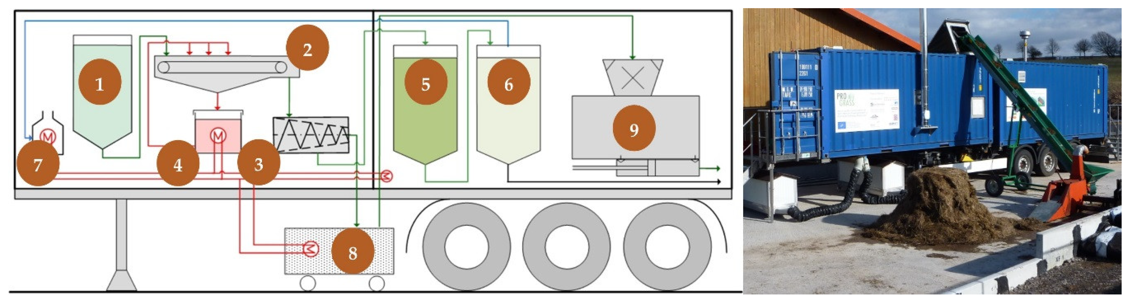
Figure 3.
Correlation between mean values for NOx emissions and N concentration in the fuel and for SO2 emissions and S concentration in the fuel.
Figure 3.
Correlation between mean values for NOx emissions and N concentration in the fuel and for SO2 emissions and S concentration in the fuel.

Figure 4.
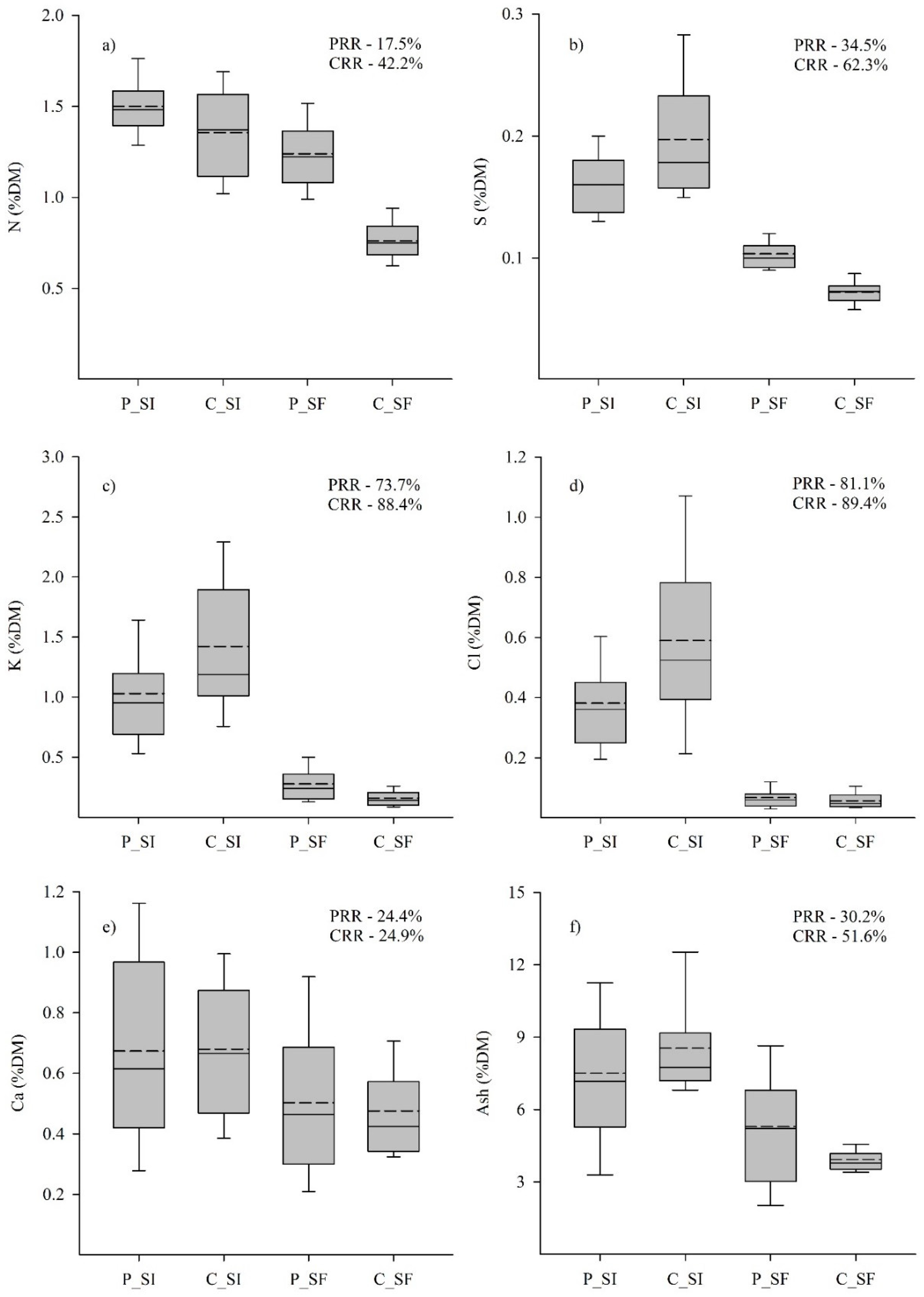
Concentration of (a) N, (b) S, (c) K, (d) Cl, (e) Ca, and (f) Ash in the silage (P_SI) and solid fuel (P_SF) on the prototype- scale and commercial-scale (C_SI, C_SF) plant. The corresponding average reduction rate for elements during dewatering for the prototype (PRR) and commercial scale (CRR) is shown in the top right corner of each plot. The dashed line in the box plots denotes the arithmetic mean and the solid line represents the median. For prototype (P) number of observations were n = 108 and for commercial scale (C) number of observations were n = 36. Boxes represent the 25th and 75th percentile and whiskers indicate the 10th and 90th percentile values excluding outliers.
Figure 4.
Concentration of (a) N, (b) S, (c) K, (d) Cl, (e) Ca, and (f) Ash in the silage (P_SI) and solid fuel (P_SF) on the prototype- scale and commercial-scale (C_SI, C_SF) plant. The corresponding average reduction rate for elements during dewatering for the prototype (PRR) and commercial scale (CRR) is shown in the top right corner of each plot. The dashed line in the box plots denotes the arithmetic mean and the solid line represents the median. For prototype (P) number of observations were n = 108 and for commercial scale (C) number of observations were n = 36. Boxes represent the 25th and 75th percentile and whiskers indicate the 10th and 90th percentile values excluding outliers.

Table 1.
Vegetation data for the grassland sites used for the study, along with regions, harvest date, and DM yield.
Table 1.
Vegetation data for the grassland sites used for the study, along with regions, harvest date, and DM yield.
| Reference Code | Dominant Species | Country (Region) | Harvest Date | DM Yield (t·ha−1) |
|---|---|---|---|---|
| AC | Agrostis capillaris, Holcus lanatus | Slovakia (Žilina) | 22.06.2013 | 5.66 |
| AE | Arrhenatherum elatius | Belgium (West Flanders) | 05.06.2013 | 1.70 |
| AM | Agrostis x murbeckii | France (Côtes-d’Armor) | n.a | n.a |
| AS | Agrostis stolonifera, Phragmites australis | Austria (Neusiedler See) | 21.06.2013 | 8.56 |
| BS | Bromus erectus, Ahrrenatherum elatius | Czech Republic (Zlin) | 20.06.2013 | 2.75 |
| CD | Carex disticha, Phragmites australis | Germany (Freising) | 27.06.2013 | 3.21 |
| DC | Deschampsia cespitosa | Wales (Caernarfon) | 27.08.2013 | 2.51 |
| JE | Juncus effusus, Carex spec., | Slovenia (Pomurje) | 24.07.2013 | 5.28 |
| PA 1 | Phalaris arundinacea | Austria (Waldviertel) | 11.09.2013 | n.a |
| PA 2 | Phalaris arundinacea, Carex riparia | Poland (Wielko-Polska) | 18.06. 2013 | 10.98 |
| PS | Phragmites australis, Carex elata | Italy (Mantova) | 05.07.2013 | 11.76 |
n.a. not available.
Table 2.
Comparison between the process parameters for prototype and commercial scale plants.
| Prototype | Commercial | ||
|---|---|---|---|
| Silage throughput | kg·day−1 | 300 | 40,000 |
| Briquette output | kg·day−1 | 90 | 8400 |
| Silage batch size | kg | 20 | 500–3500 |
| Conditioning temperature | °C | 25 | 10 |
| Conditioning time | min | 30 | 40 |
| Silage to water ratio | 1:8 | 1:15 | |
Table 3.
Ultimate analysis, heating values, elemental concentration and corrosion index for silage (SI) and solid fuel (SF), along with the reduction rate (RR) from silage to solid fuel for test materials processed in the commercial-scale pilot plant (see Table 1). The values in parentheses denote an increase in concentration from silage to press cake.
| AC | AE | AM | AS | BS | CD | DC | JE | PA 1 | PA 2 | PS | Mean | |||
|---|---|---|---|---|---|---|---|---|---|---|---|---|---|---|
| DM | %FM | SI | 55.18 | 66.01 | 27.32 | 31.67 | 82.54 | 62.23 | 38.42 | 66.32 | 56.35 | 39.54 | 44.11 | 55.91 |
| SF | 31.51 | 28.20 | 29.43 | 77.00 | 24.55 | 33.25 | 32.46 | 26.61 | 30.25 | 31.68 | 29.67 | 29.93 | ||
| LHV | SI | 17.12 | 17.55 | 16.67 | 17.47 | 17.32 | 17.26 | 17.81 | 17.33 | 16.70 | 17.54 | 17.48 | 17.30 | |
| SF | 17.69 | 17.69 | 17.56 | 17.80 | 17.69 | 17.65 | 17.84 | 17.78 | 17.55 | 17.94 | 17.82 | 17.72 | ||
| Ash | %DM | SI | 9.89 | 7.40 | 13.96 | 5.69 | 7.23 | 8.49 | 7.07 | 7.91 | 11.80 | 7.22 | 7.88 | 8.59 |
| SF | 3.59 | 3.88 | 4.40 | 3.59 | 3.76 | 4.74 | 3.54 | 4.42 | 4.52 | 3.54 | 3.74 | 3.97 | ||
| RR | 63.70 | 47.57 | 68.48 | 36.91 | 47.99 | 44.17 | 49.93 | 44.12 | 61.69 | 50.97 | 52.54 | 51.64 *** | ||
| N | %DM | SI | 1.40 | 1.58 | 1.79 | 0.96 | 1.16 | 1.50 | 1.64 | 1.09 | 1.52 | 1.23 | 1.07 | 1.36 |
| SF | 0.68 | 0.89 | 0.66 | 0.73 | 0.76 | 0.96 | 0.79 | 0.86 | 0.70 | 0.70 | 0.58 | 0.76 | ||
| RR | 51.43 | 43.67 | 63.13 | 23.96 | 34.48 | 36.00 | 51.83 | 21.10 | 53.95 | 43.09 | 45.79 | 42.58 *** | ||
| S | %DM | SI | 0.16 | 0.18 | 0.20 | 0.29 | 0.14 | 0.17 | 0.23 | 0.15 | 0.17 | 0.28 | 0.23 | 0.20 |
| SF | 0.06 | 0.07 | 0.06 | 0.09 | 0.06 | 0.08 | 0.08 | 0.07 | 0.07 | 0.09 | 0.07 | 0.07 | ||
| RR | 62.50 | 61.11 | 70.00 | 68.97 | 57.14 | 52.94 | 65.22 | 53.33 | 58.82 | 67.86 | 69.57 | 62.50 *** | ||
| Cl | %DM | SI | 0.22 | 0.45 | 1.24 | 0.44 | 0.21 | 1.01 | 0.86 | 0.50 | 0.54 | 0.61 | 0.64 | 0.61 |
| SF | 0.04 | 0.04 | 0.11 | 0.04 | 0.03 | 0.06 | 0.11 | 0.05 | 0.04 | 0.08 | 0.05 | 0.06 | ||
| RR | 81.82 | 91.11 | 91.13 | 90.91 | 85.71 | 94.06 | 87.21 | 90.00 | 92.59 | 86.89 | 92.19 | 89.42 *** | ||
| K | %DM | SI | 2.81 | 0.95 | 1.96 | 0.65 | 2.08 | 1.33 | 1.02 | 1.86 | 1.16 | 0.82 | 1.15 | 1.44 |
| SF | 0.32 | 0.08 | 0.22 | 0.09 | 0.25 | 0.17 | 0.16 | 0.20 | 0.11 | 0.11 | 0.10 | 0.16 | ||
| RR | 88.61 | 91.58 | 88.78 | 86.15 | 87.98 | 87.22 | 84.31 | 89.25 | 90.52 | 86.59 | 91.30 | 88.39 *** | ||
| Ca | %DM | SI | 0.64 | 0.54 | 0.69 | 0.33 | 0.87 | 0.86 | 0.41 | 0.54 | 0.45 | 1.17 | 0.90 | 0.67 |
| SF | 0.53 | 0.43 | 0.33 | 0.32 | 0.81 | 0.60 | 0.35 | 0.61 | 0.34 | 0.41 | 0.44 | 0.47 | ||
| RR | 17.19 | 20.37 | 52.17 | 3.03 | 6.90 | 30.23 | 14.63 | (12.96) | 24.44 | 64.96 | 51.11 | 24.73 *** | ||
| Mg | %DM | SI | 0.16 | 0.21 | 0.18 | 0.34 | 0.15 | 0.26 | 0.23 | 0.19 | 0.21 | 0.24 | 0.20 | 0.22 |
| SF | 0.06 | 0.06 | 0.04 | 0.09 | 0.08 | 0.08 | 0.08 | 0.07 | 0.05 | 0.05 | 0.05 | 0.06 | ||
| RR | 62.50 | 71.43 | 77.78 | 73.53 | 46.67 | 69.23 | 65.22 | 63.16 | 76.19 | 79.17 | 75.00 | 69.08 *** | ||
| P | %DM | SI | 0.33 | 0.27 | 0.26 | 0.1 | 0.22 | 0.18 | 0.21 | 0.17 | 0.19 | 0.18 | 0.12 | 0.20 |
| SF | 0.05 | 0.05 | 0.06 | 0.04 | 0.08 | 0.06 | 0.05 | 0.05 | 0.06 | 0.04 | 0.04 | 0.05 | ||
| RR | 84.85 | 81.48 | 76.92 | 60.00 | 63.64 | 66.67 | 76.19 | 70.59 | 68.42 | 77.78 | 66.67 | 72.11 *** | ||
| Na | %DM | SI | 0.01 | 0.37 | 0.29 | 0.19 | 0.01 | 0.09 | 0.42 | 0.02 | 0.04 | 0.08 | 0.05 | 0.14 |
| SF | 0.05 | 0.07 | 0.07 | 0.06 | 0.06 | 0.05 | 0.01 | 0.05 | 0.05 | 0.04 | 0.04 | 0.05 | ||
| RR | (400) | 81.08 | 75.86 | 68.42 | (500) | 44.44 | 76.19 | (150) | (25) | 50 | 20 | (59.91) | ||
| 2S/Cl | SI | 1.61 | 0.91 | 0.35 | 1.45 | 1.52 | 0.37 | 0.58 | 0.67 | 0.71 | 1.03 | 0.82 | 0.91 | |
| SF | 3.14 | 4.08 | 1.22 | 5.57 | 4.60 | 2.58 | 1.64 | 3.37 | 3.81 | 2.32 | 2.95 | 3.20 | ||
*** p < 0.001 ** p < 0.01 * p < 0.05.
Table 4.
Mean ash softening and flow temperature for silage (SI) and solid fuel (SF).
| Ash Softening Temperature | Ash Flowing Temperature | |||
|---|---|---|---|---|
| °C | °C | |||
| SI | SF | SI | SF | |
| AC | 1070 | 1050 | 1260 | 1297 |
| AE | 1040 | 1097 | 1290 | 1277 |
| AM | 1080 | 1143 | 1300 | 1353 |
| AS | 1023 | 1370 | 1243 | 1467 |
| BS | 1163 | 1170 | 1307 | 1277 |
| CD | 1153 | 1147 | 1280 | 1290 |
| DC | 1067 | 1077 | 1217 | 1273 |
| JE | 1027 | 1147 | 1213 | 1260 |
| PA 1 | 1157 | 1183 | 1377 | 1423 |
| PA 2 | 1167 | 1230 | 1247 | 1377 |
| PS | 1157 | 1180 | 1297 | 1400 |
| Mean | 1100 | 1163 | 1275 | 1336 |
Table 5.
Mean values of CO, NOx, SO2, PM, and excess air fuel ratio (λ) emissions during combustion of solid fuel briquettes at partial load (60 kW) and full load (120 kW).
Table 5.
Mean values of CO, NOx, SO2, PM, and excess air fuel ratio (λ) emissions during combustion of solid fuel briquettes at partial load (60 kW) and full load (120 kW).
| NOx | CO | SO2 | PM | (λ) | |||||||
|---|---|---|---|---|---|---|---|---|---|---|---|
| Partial Load | Full Load | Partial Load | Full Load | Partial Load | Full Load | Partial Load | Full Load | Partial Load | Full Load | ||
| AC | mg m−3 | 352.32 | 357.20 | 627.35 | 36.20 | 2.91 | 34.91 | 103.48 | 55.38 | 2.9 | 1.9 |
| AE | mg m−3 | 567.65 | 404.03 | 276.49 | 52.88 | 16.23 | 58.41 | 35.04 | 37.24 | 3.1 | 1.8 |
| AM | mg m−3 | 348.53 | 353.33 | 337.20 | 75.38 | 20.57 | 41.41 | 65.13 | 43.18 | 2.9 | 2 |
| CD | mg m−3 | 438.20 | 467.71 | 497.00 | 173.87 | 26.04 | 40.73 | 65.72 | 49.58 | 3.7 | 2.6 |
| DC | mg m−3 | 399.62 | 405.60 | 407.46 | 38.21 | 10.99 | 58.53 | 77.88 | 50.77 | 3 | 1.8 |
| PA2 | mg m−3 | 359.41 | 349.52 | 169.26 | 94.56 | 48.31 | 70.82 | 26.08 | 30.30 | 2.8 | 1.7 |
| Legal threshold a | 500 | 250 | 350 | 50 | |||||||
a—Emission thresholds in Germany for combustion with fuel input between 0.1–1 MW for non-wood biomass at 11% O2 [55]
© 2018 by the authors. Licensee MDPI, Basel, Switzerland. This article is an open access article distributed under the terms and conditions of the Creative Commons Attribution (CC BY) license (http://creativecommons.org/licenses/by/4.0/).
Share and Cite
MDPI and ACS Style
Joseph, B.; Hensgen, F.; Bühle, L.; Wachendorf, M. Solid Fuel Production from Semi-Natural Grassland Biomass—Results from a Commercial-Scale IFBB Plant. Energies 2018, 11, 3011. https://doi.org/10.3390/en11113011
AMA Style
Joseph B, Hensgen F, Bühle L, Wachendorf M. Solid Fuel Production from Semi-Natural Grassland Biomass—Results from a Commercial-Scale IFBB Plant. Energies. 2018; 11(11):3011. https://doi.org/10.3390/en11113011
Chicago/Turabian StyleJoseph, Ben, Frank Hensgen, Lutz Bühle, and Michael Wachendorf. 2018. "Solid Fuel Production from Semi-Natural Grassland Biomass—Results from a Commercial-Scale IFBB Plant" Energies 11, no. 11: 3011. https://doi.org/10.3390/en11113011
Note that from the first issue of 2016, this journal uses article numbers instead of page numbers. See further details here.