Article

Investigation of an Innovative Cascade Cycle Combining a Trilateral Cycle and an Organic Rankine Cycle (TLC-ORC) for Industry or Transport Application

1
Department of Energy Engineering, Zhejiang University, Hangzhou 310027, China
2
Sir Joseph Swan Centre for Energy Research, Newcastle University, Newcastle NE1 7RU, UK
*
Author to whom correspondence should be addressed.
Energies 2018, 11(11), 3032; https://doi.org/10.3390/en11113032
Submission received: 1 October 2018 / Revised: 26 October 2018 / Accepted: 1 November 2018 / Published: 5 November 2018
(This article belongs to the Special Issue Applications for the Organic Rankine Cycle)

Abstract

:
An innovative cascade cycle combining a trilateral cycle and an organic Rankine cycle (TLC-ORC) system is proposed in this paper. The proposed TLC-ORC system aims at obtaining better performance of temperature matching between working fluid and heat source, leading to better overall system performance than that of the conventional dual-loop ORC system. The proposed cascade cycle adopts TLC to replace the High-Temperature (HT) cycle of the conventional dual-loop ORC system. The comprehensive comparisons between the conventional dual-loop ORC and the proposed TLC-ORC system have been conducted using the first and second law analysis. Effects of evaporating temperature for HT and Low-Temperature (LT) cycle, as well as different HT and LT working fluids, are systematically investigated. The comparisons of exergy destruction and exergy efficiency of each component in the two systems have been studied. Results illustrate that the maximum net power output, thermal efficiency, and exergy efficiency of a conventional dual-loop ORC are 8.8 kW, 18.7%, and 50.0%, respectively, obtained by the system using cyclohexane as HT working fluid at THT,evap = 470 K and TLT,evap = 343 K. While for the TLC-ORC, the corresponding values are 11.8 kW, 25.0%, and 65.6%, obtained by the system using toluene as a HT working fluid at THT,evap = 470 K and TLT,evap = 343 K, which are 34.1%, 33.7%, and 31.2% higher than that of a conventional dual-loop ORC.

1. Introduction

Heat recovery technologies have attracted increasing attention around the world due to the increase in fuel prices, rigorous emission regulations, and concerns about environmental problems associated with the use of existing energy systems [1,2]. A number of waste heat recovery technologies have been proposed, such as organic Rankine cycles (ORCs) [3,4], Rankine cycles [5], absorption/adsorption cycles [6], Kalina cycles [7], thermoacoustic engines [8], and thermofluidic oscillators [9,10]. Among the stated cycles, ORC-based technologies are one of the most promising solutions because of their relatively high efficiency and simple configurations [11,12]. ORC technologies have been widely investigated and can be used to recover heat sources such as the waste heat from internal combustion engines [13,14], solar energy [15,16], geothermal, and other industrial applications [3,17,18]. However, the heat transfer process of a conventional ORC system in the evaporator suffers from poor performance of temperature matching between the heat source and working fluid due to the phase-change evaporating process, causing relatively high exergy destruction and poor thermodynamic performance [19,20]. Using mixture fluids can potentially solve the stated problem due to the non-isothermal process in the evaporator [21,22]. However, it is difficult to develop the mixture fluids, and their thermodynamic performance need to be further investigated [23].
The trilateral cycle (TLC) was previously proposed, which has a better thermal match from the heat source to the working fluid than conventional ORCs [7,24,25]. The characteristic of the TLC is that the working fluid directly flows into the expander after being heated in the evaporator without any evaporating process. Therefore, the temperature difference between the working fluid and heat source in the evaporator can be smaller than that of a conventional ORC, leading to an overall smaller exergy loss in the evaporator [26]. Johann Fischer compared the performance of a TLC and an ORC for waste heat recovery [27]. Results showed the exergy efficiency of the TLC can be 14–29% higher than that of a conventional ORC under the same operational conditions. M. Yari et al. studied TLC, ORC, and Kalina cycle using an exergoeconomic analysis method [7]. Results indicated TLC has better power output performance than that of ORC and Kalina cycle, but that the device cost is mainly determined by the isentropic efficiency of the selected expansion machine. A comparison of different pure working fluids illustrated that adopting n-butane can reduce the cost of the TLC system. Ramon Ferreiro Garcia et al. [28] pointed out that within a range of relatively low operating temperatures, the TLC can obtain an overall thermal efficiency at 44.9% compared to 33.9% of a Carnot cycle under the same high and low-temperature heat reservoir conditions [28]. Cipollone et al. [29] conducted a thermodynamic analysis of the TLC system considering the potential to use rotary positive displacement expanders as the expansion device to achieve two-phase expansion of the TLC. The reported feasibility study mainly focusing on the effects of using pure and mixture fluids on volumetric expansion machines under 10 kW power output [29]. The importance of considering the built-in volume expansion ratio for the TLC system was addressed, and results suggested that a relatively large built-in volume expansion ratio is required to produce a great specific work [29], which means that in order to achieve overall good performance, volumetric expansion machines are generally not recommend for use with TLC systems.
Previous studies indicated the overall performance of the heat recovery system using the TLC system can be higher than that of a conventional ORC system under the same operational conditions. However, previously-reported research on the TLC is mainly focusing on the performance studies of a single loop system. A single-loop TLC system will require a large evaporator heat exchanger to effectively and efficiently recover high-temperature heat sources such as from industrial processes and the transport sector. Moreover, a single-loop TLC cannot be used for multi-heat source recovery, which has less flexibility compared to a dual-loop cycle or cascaded systems. Extensive research efforts have been made on the dual-loop ORC system, because the system can effectively and efficiently convert dual heat sources into useful power. Moreover, dual-loop ORC technology has the advantage of being able to comprehensively recover a single heat source with a high-temperature profile. Wang et al. [30] first proposed the concept of a dual-loop ORC and investigated the performance of the system recovering engine exhaust and coolant energy from a gasoline engine. The results showed that the absolute effective thermal efficiency for the objective engine was improved by 3~6% under all operating conditions. Zhang et al. [31] designed a novel dual-loop ORC to recover the waste heat of exhaust gas, intake air, and coolant energy from a light-duty diesel engine. Results indicated that the effective power of the diesel engine can be improved by 14~16% and 38~43%, corresponding to peak effective thermal efficiency and low load (and high speed) conditions. Other representative works have been conducted by Shu and Tian et al. [22,32,33] and Song and Gu et al. [34,35]. Results showed that the system performed better at a high operating load, and R1234yf was found to be the best working fluid. Using water as the working fluid of the HT loop, the system obtained maximum net output power (39.67 kW) and exergy efficiency (42.98%) [32,33]. Song et al. [35] conducted a parametric study based on a dual-loop ORC system. Key parameters including condensation temperature of the high-temperature cycle and working fluids for high-temperature and low-temperature cycles were considered. The results based on a simulation showed that the maximum net power output could achieve as high as 111.2 kW by the proposed dual-loop ORC, increasing the engine power by 11.2% with cyclohexane and R236fa as high-temperature and low-temperature working fluid, respectively [35].
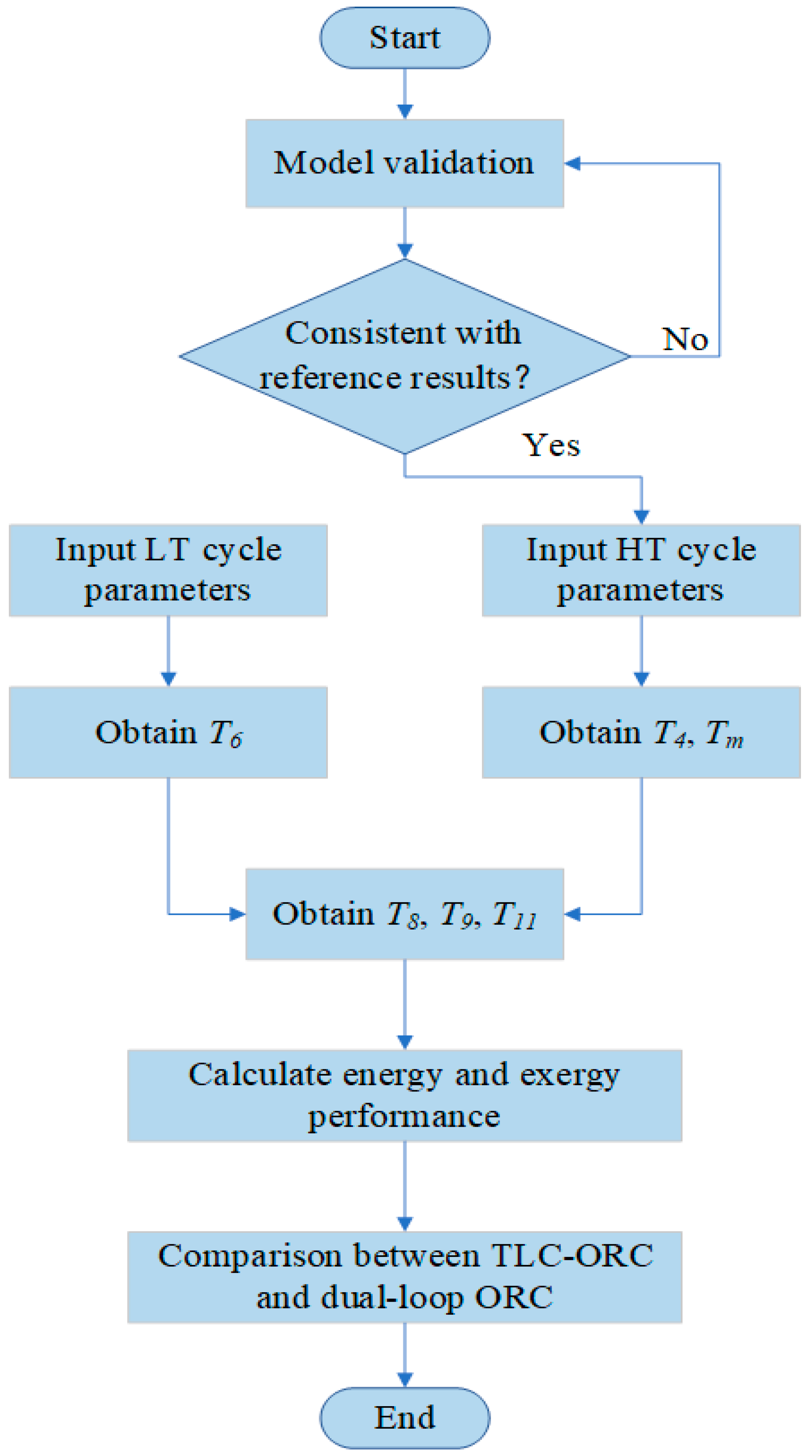
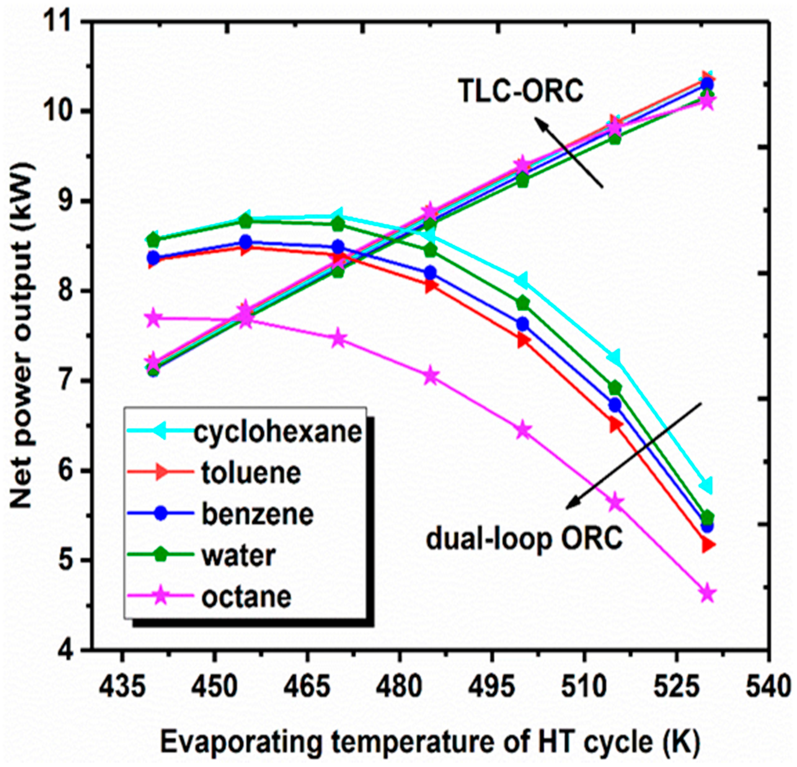
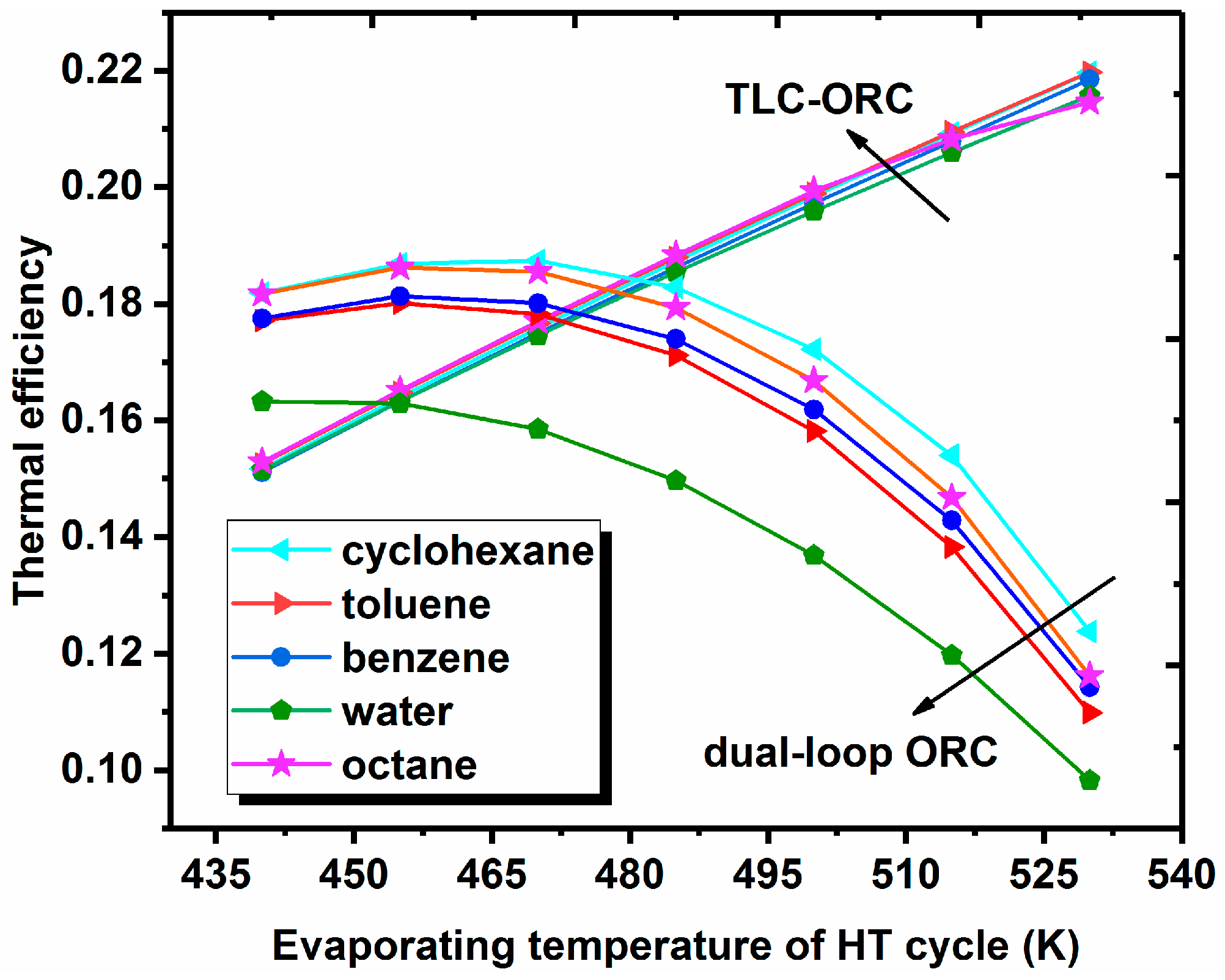
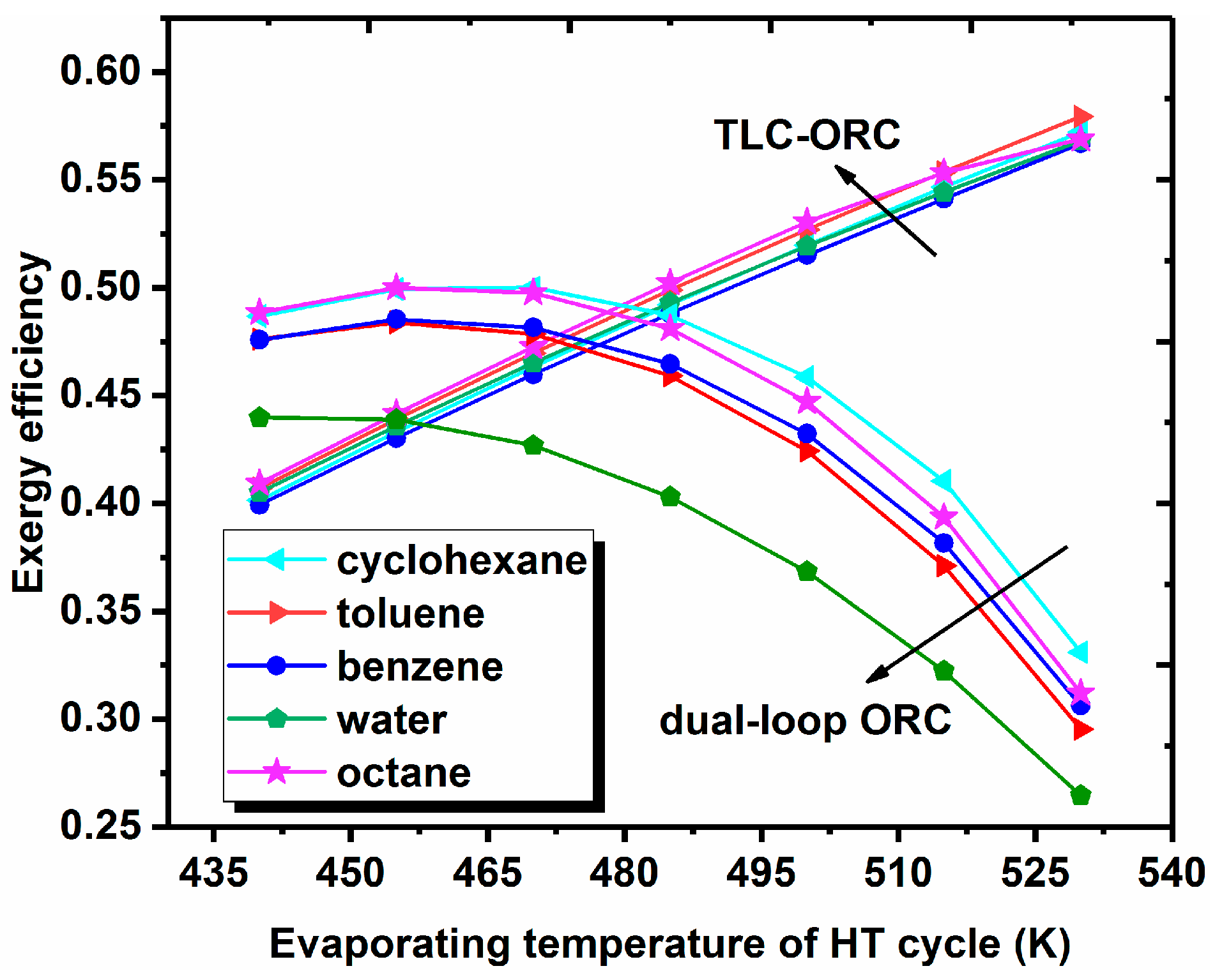
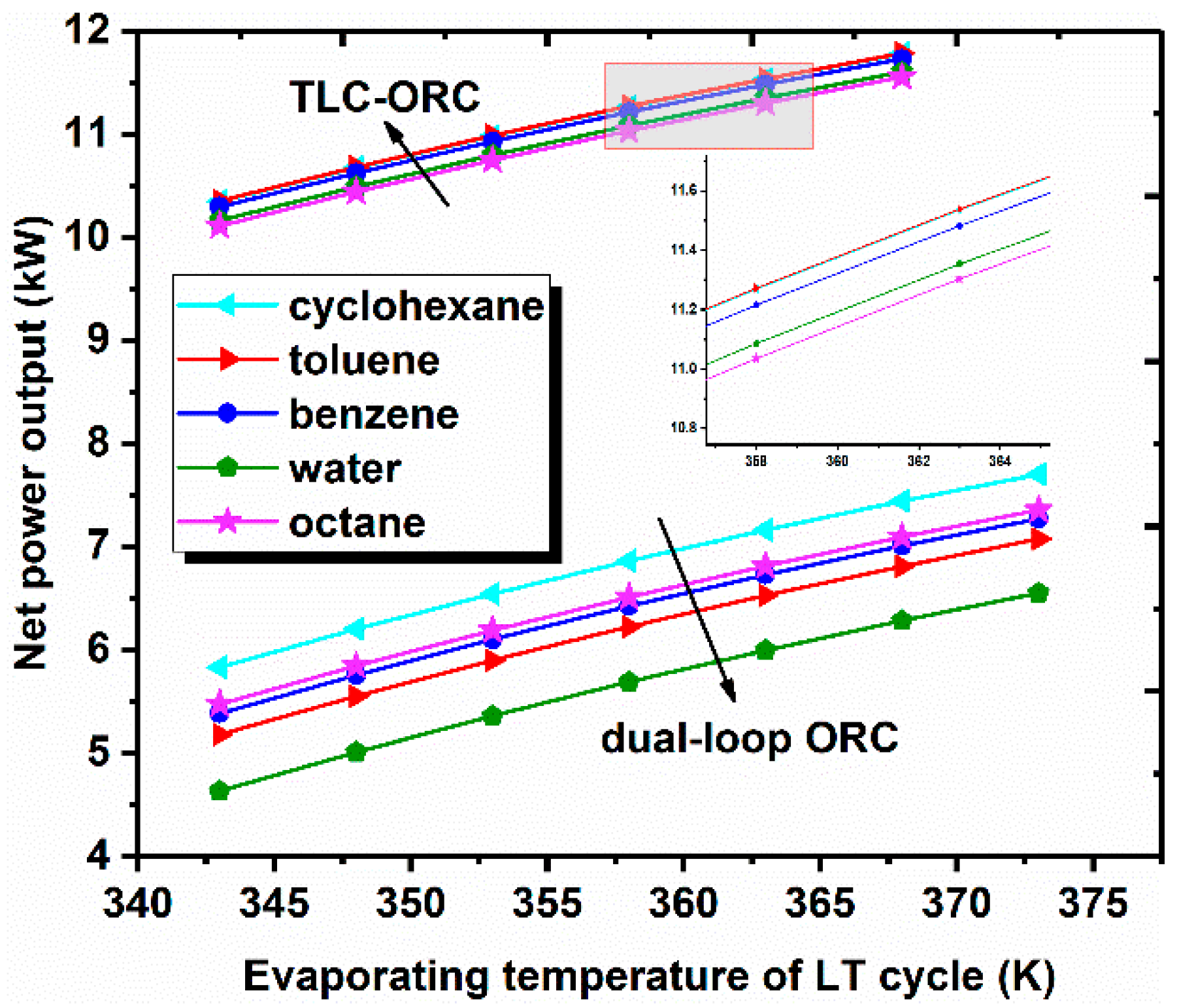
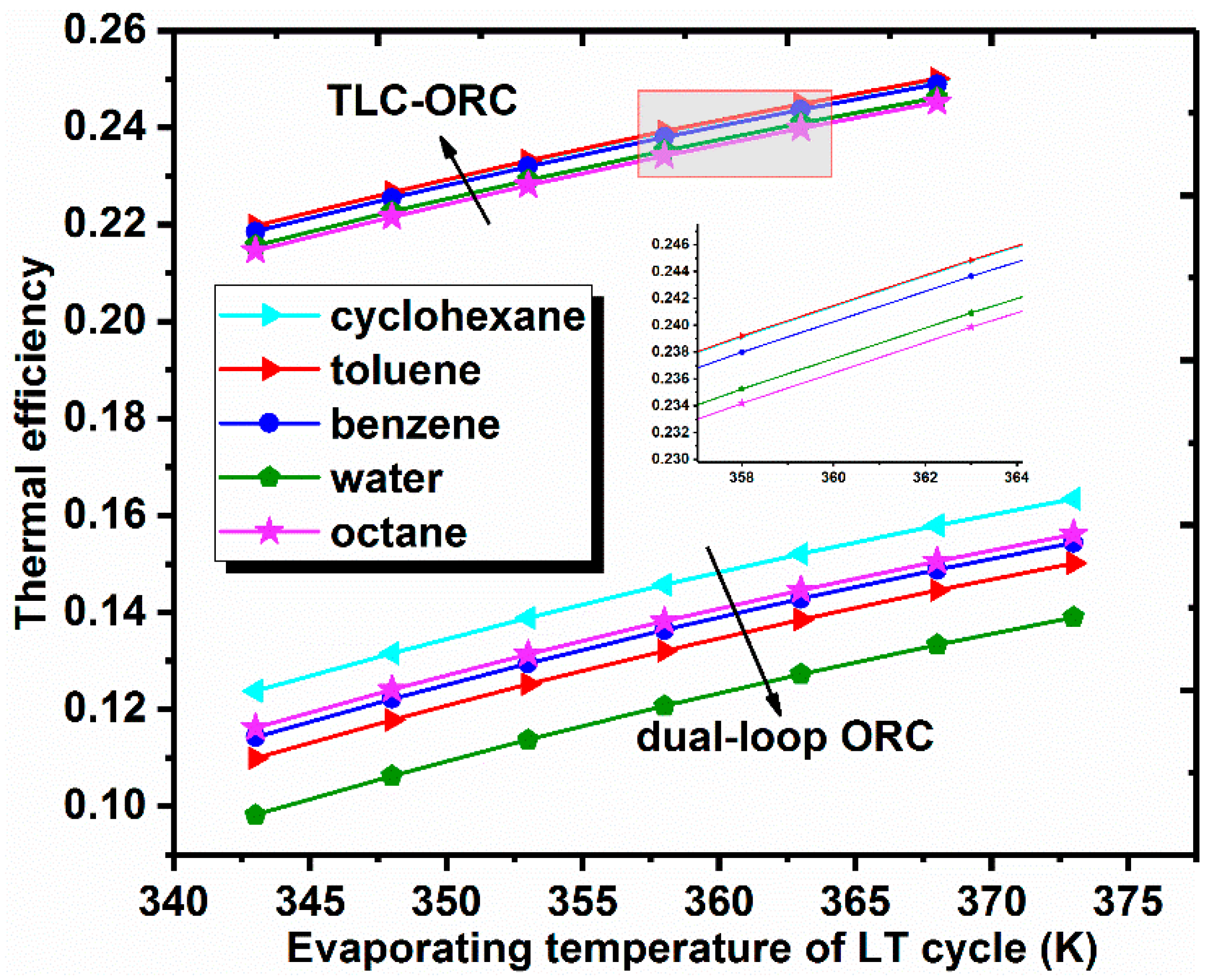
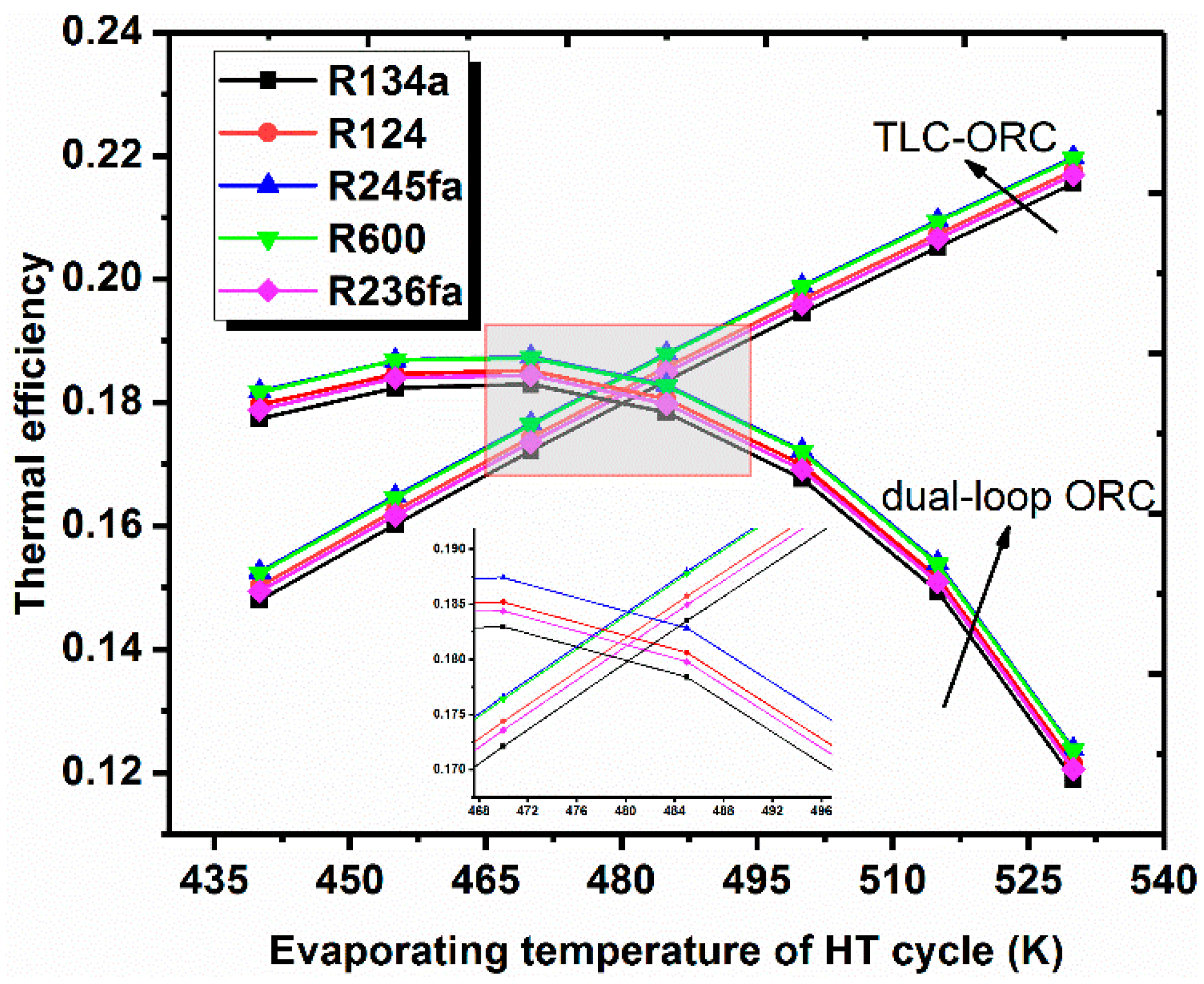
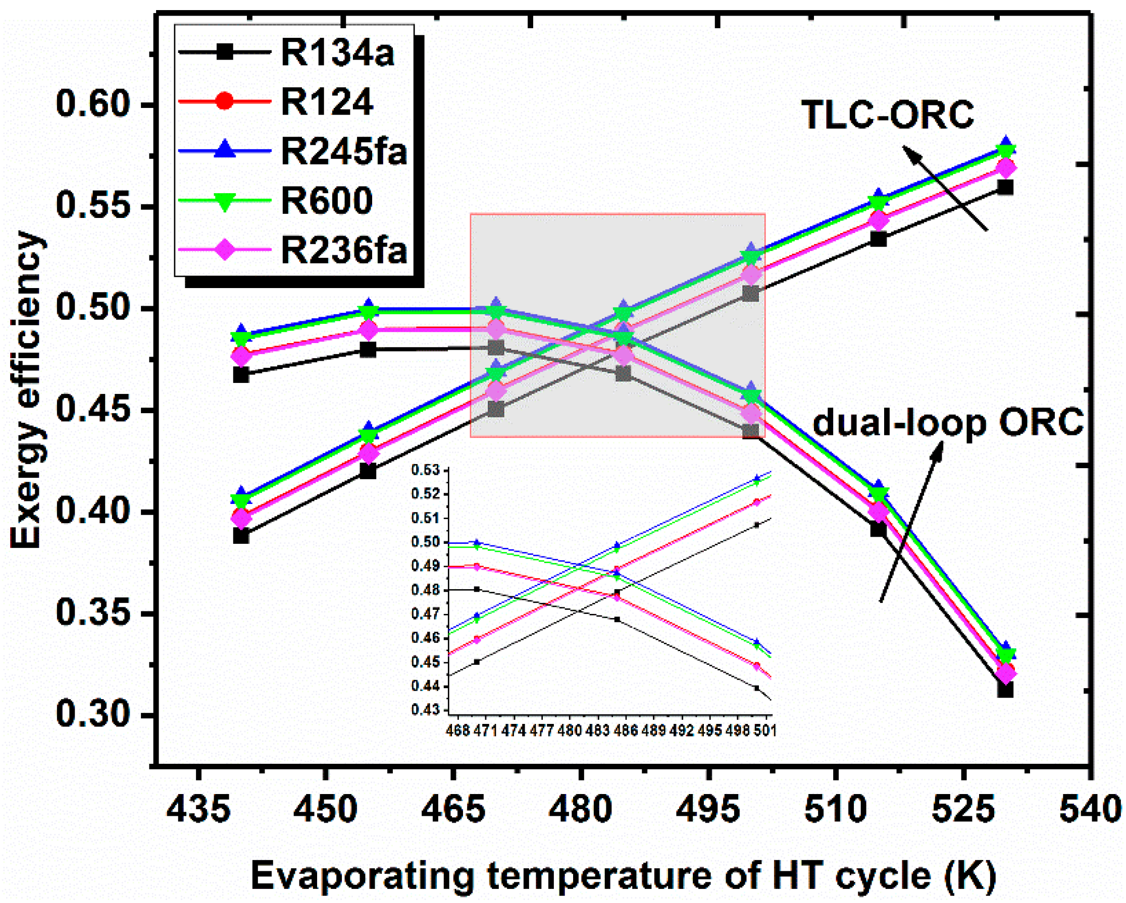
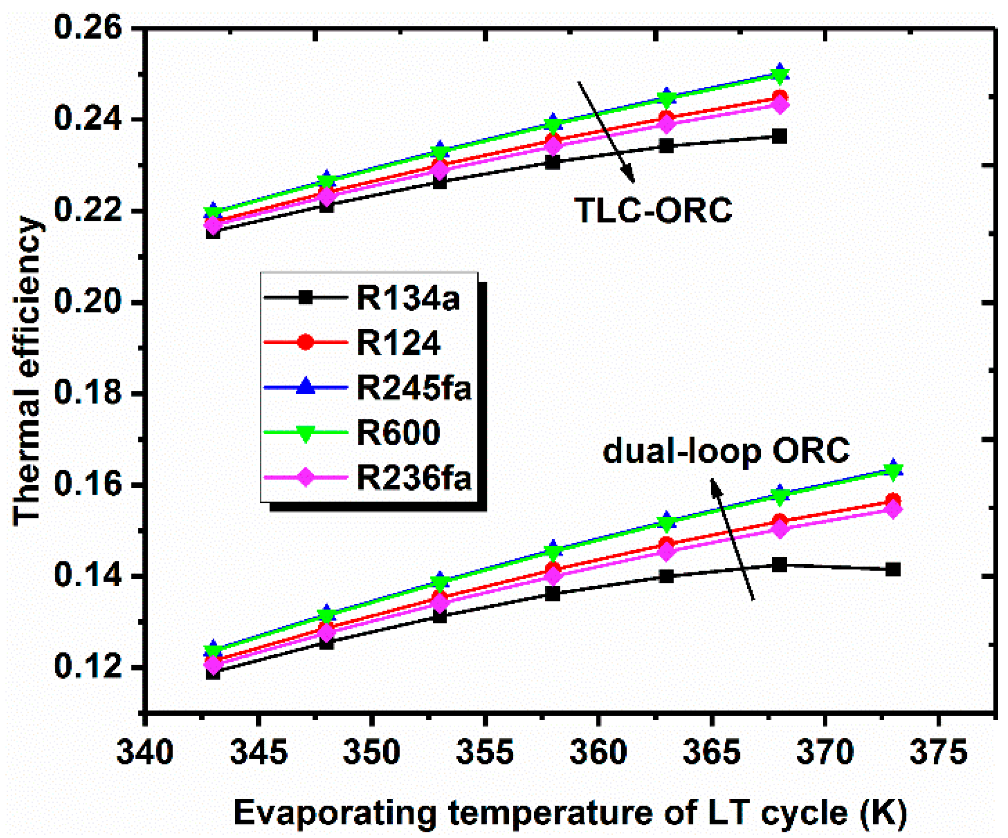
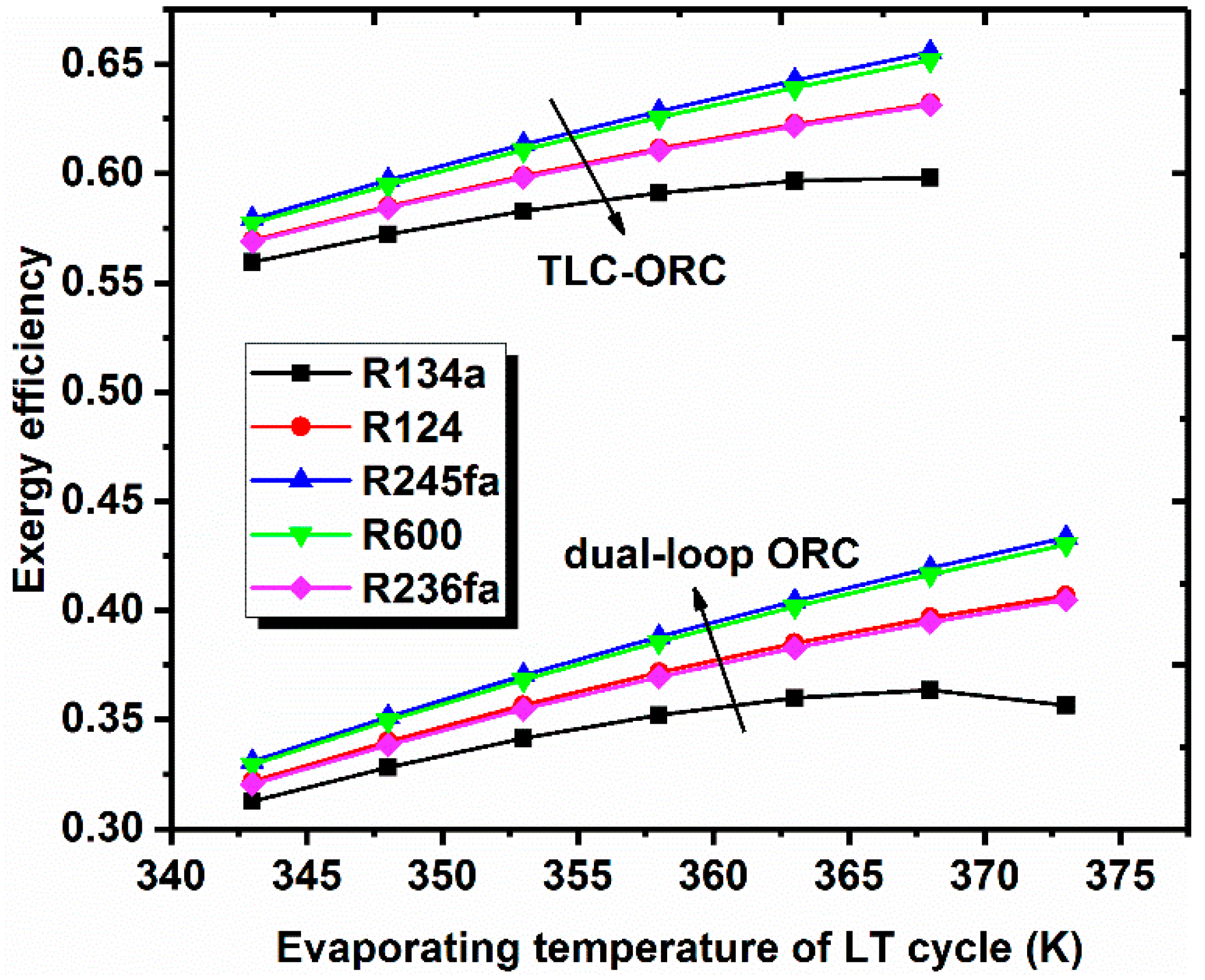
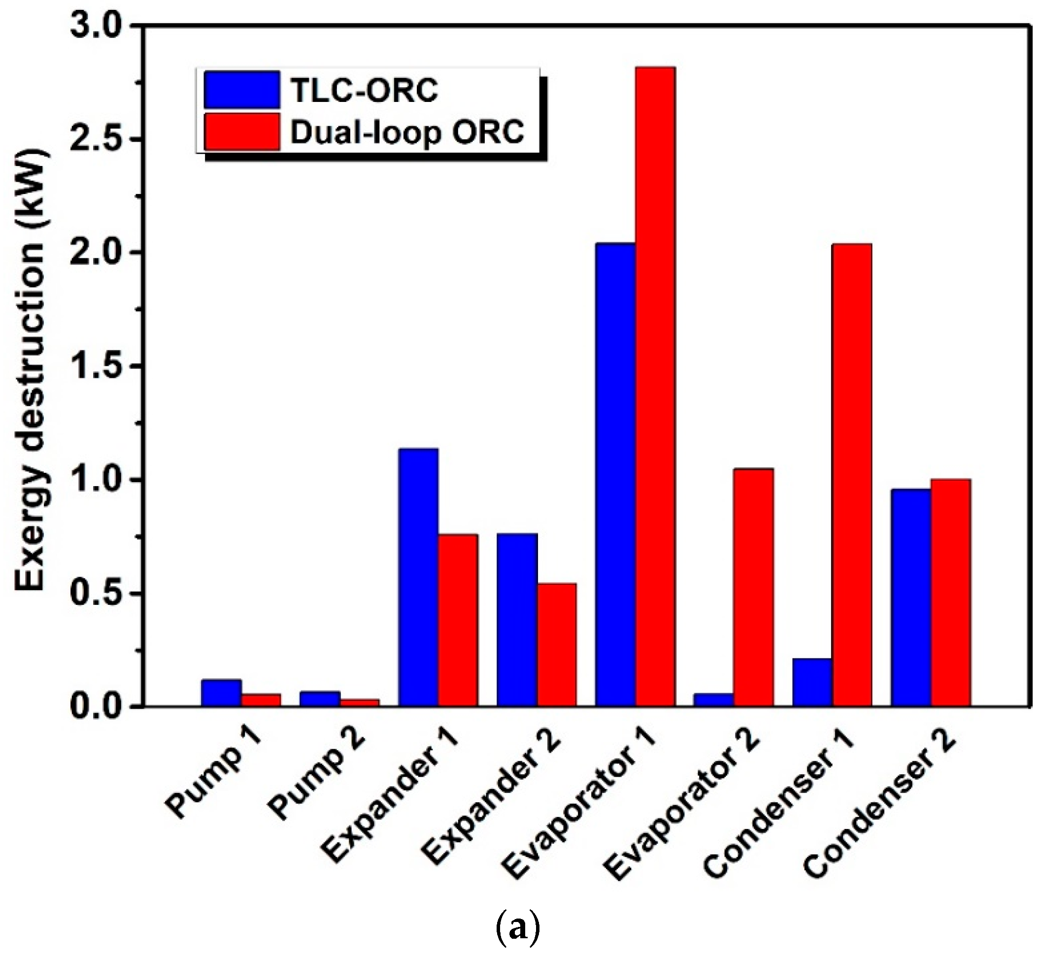
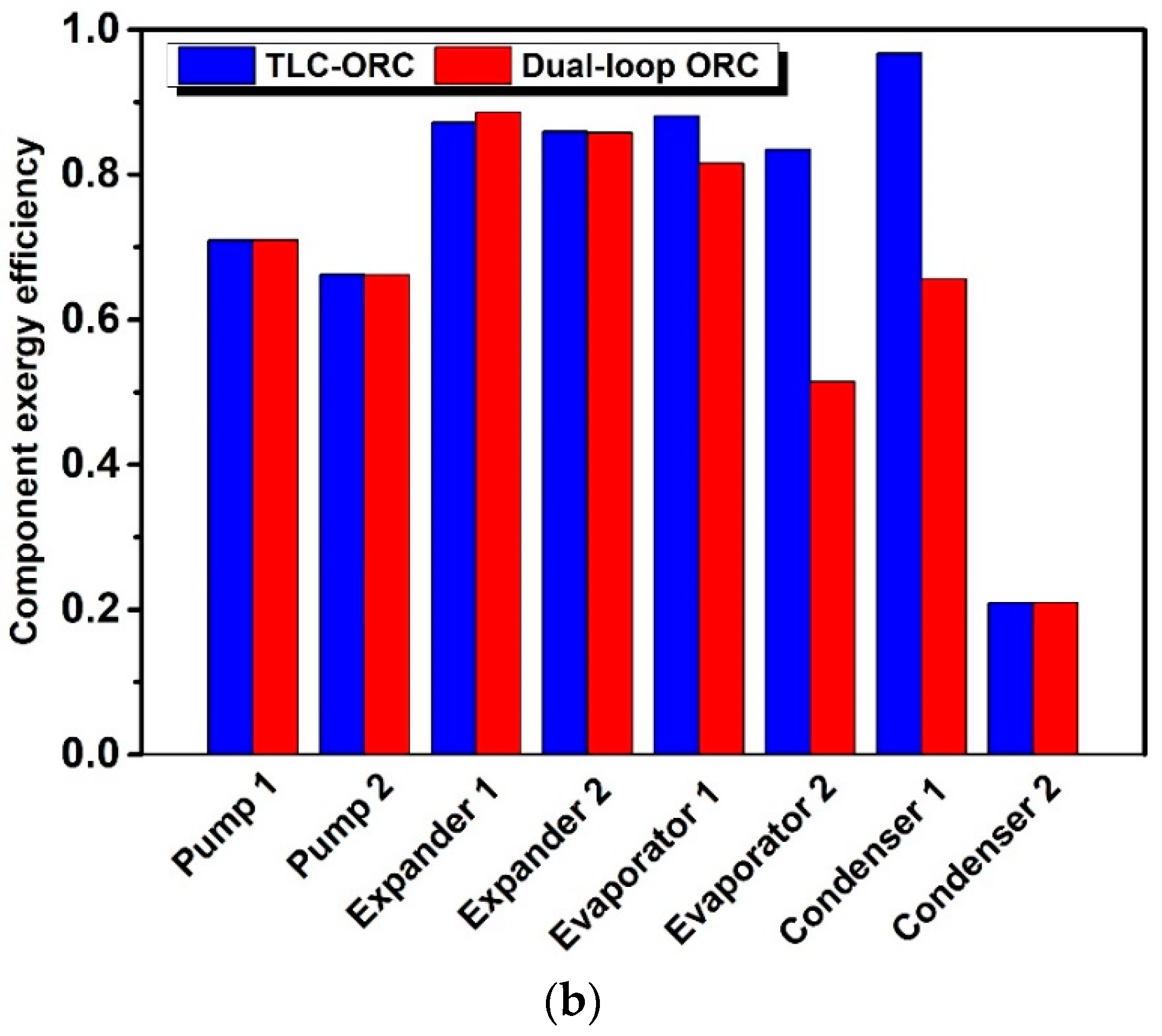
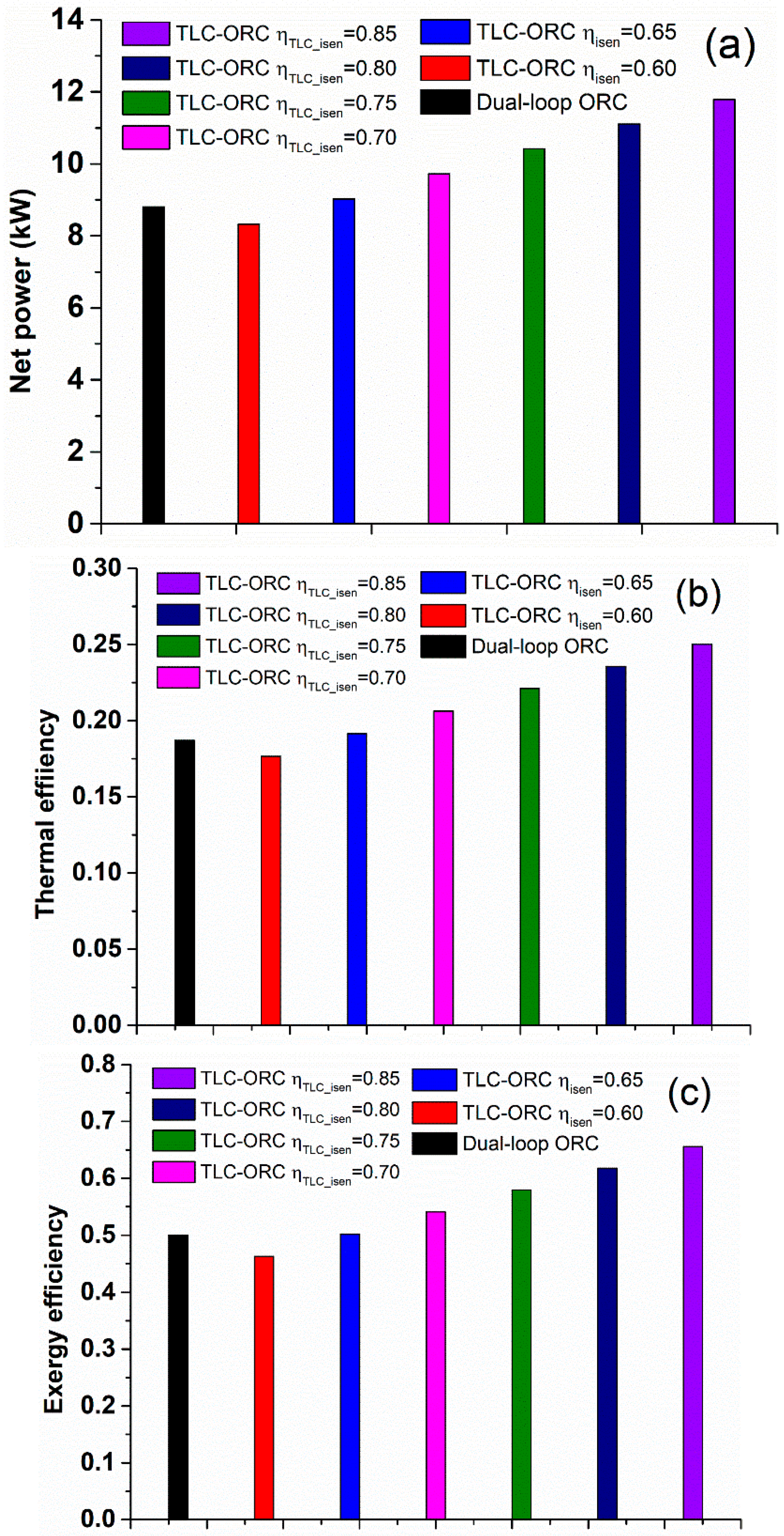
In summary, previous studies have compared the TLC with other power generation cycles, and have proven the TLC has great potential for heat recovery. Meanwhile, the superiority of using dual-loop ORC has been revealed, which can be used to effectively recover multi-heat sources, although large exergy loss still exists in the evaporator of the dual-loop ORC system. Therefore, in this study, the TLC has been introduced into a conventional dual-loop ORC system to form an innovative cascade system with the purpose of adding flexibility of the TLC for the potential application of multi-heat source recovery, and improving the overall energy efficiency of a conventional dual-loop ORC system. This study aims to study the thermodynamic performance of the proposed TLC-ORC system and conduct a comparative investigation of the conventional dual-loop ORC system under the same operational conditions. The key factors of the systems investigated in this work include the net power output, thermal efficiency, exergy efficiency, HT working fluids, LT working fluids, and the evaporating temperature of HT and LT cycles.

2. System Description

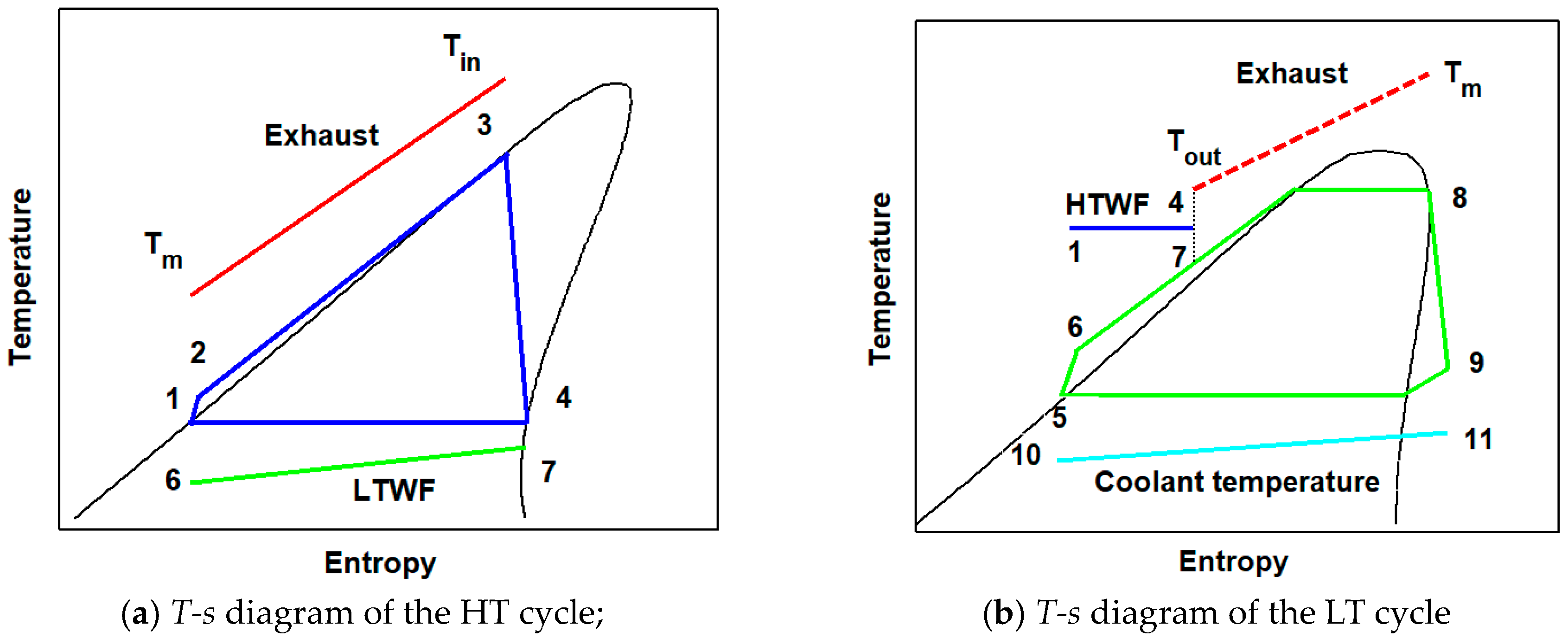
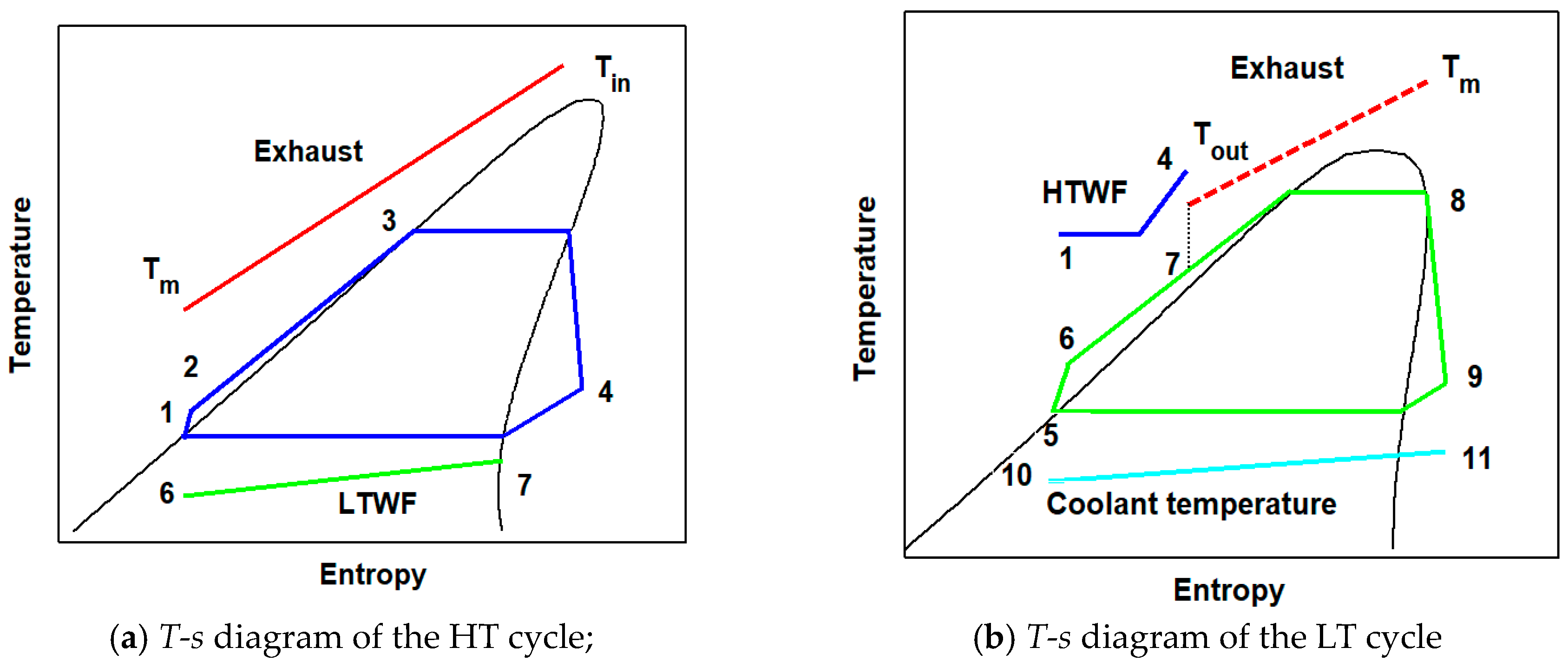
Figure 1 shows the layout of the proposed combined TLC-ORC waste heat recovery system, which consists of a High-Temperature (HT) loop and a Low-Temperature (LT) loop. The schematic diagram of the TLC-ORC is the same as the conventional dual-loop ORC system illustrated in Figure 1. The TLC is used to replace the HT loop, as shown in the dashed black line. The condensation heat from the TLC is used to preheat the working fluid in the LT loop. In order to understand and compare the working process of the TLC-ORC and a conventional dual-loop ORC system, the T-s diagrams of two systems are respectively presented in Figure 2 and Figure 3. The other technical challenge that should be noted is the expansion machine to be used in the TLC system, which would be forced to operate under two-phase conditions. Recently, works have confirmed the feasibility of using a screw-type expander [27,36] or a reciprocating engine [37] for the TLC system.
A comparison of the working principle between the proposed TLC-ORC and a conventional dual-loop ORC is illustrated in Figure 2 and Figure 3. The HT cycle of the TLC-ORC system maintains the working fluid as the liquid state before entering the expansion machine, which can potentially achieve a better thermal match of the heat source conditions. The detailed working process of the TLC is explained as follows, and is shown in Figure 2a. In state 1, working fluid is in a saturated liquid state at temperature T1 and vapor pressure p1. Then, the pressure is increased to p2 by pump 1 at the state 2 in the homogeneous liquid. The liquid-phase working fluid enters the heat exchanger where it is heated to boiling point at pressure p2, which is state 3. The temperature T3 is the boiling temperature at pressure p2. Starting from state 3, the working fluid directly enters the two-phase expander. In the two-phase expander, the working liquid expands into the wet vapor region, and gradually reaches the wet saturated vapor state (state 4), as shown in Figure 2a. The authors would like to point out the dryness of the working fluid at state 4 is determined by the calculation after the expansion process and condensation pressure controlled by the condenser. The working fluid at state 4 can be either saturated vapor, the wet state, or within the two-phase region. The wet saturated vapor is condensed until it reaches state 1. For the LT cycle in the TLC-ORC system, LT working fluid starts at state 5 with saturated liquid. Then, it is pressured to state 2 with pressure p6 by pump 2. The LT working fluid absorbs residual heat from HT working fluid in condenser 1, and continues to absorb the waste heat of exhaust in evaporator 2. At the outlet of evaporator 2 (state 8), LT working fluid is saturated vapor; then, it flows into expander 2 to convert thermal energy to effective work by expanding the process. At state 9, LT working fluid is low pressure and it is condensed to saturated liquid at state 5 by cooling water. The working process of a traditional dual-loop ORC is similar to that of the proposed TLC-ORC. The main differences are the evaporating and condensing processes of the HT working fluid. The detailed working process of conventional dual-loop ORC can be found in reference [38].

3. Selection of Working Fluids

In order to investigate the characteristics of the TLC-ORC, the effects of different working fluids for HT cycle and LT cycle on system performance should be investigated. The selection of ORC working fluids should consider the following criteria [32,39,40,41].
(1)
Safety. Working fluid should be less flammable and toxic, or corrosive to pipes and other devices.
(2)
Environmental impact. Subjected to rigorous regulations, working fluid should have small potential issues when leaking to the environment.
(3)
Chemical stability. Working fluid should have a high decomposition temperature when recovering the waste heat of high-temperature heat.
(4)
Thermo-physical properties. Working fluid should have high vapor density, low viscosity, proper critical temperature, and freezing temperature.
According to the stated selection principles, five HT working fluids, i.e., cyclohexane, toluene, benzene, water, and octane, and five LT working fluids, i.e., R134a, R124, R245fa, R600, and R236fa, are selected. Detailed parameters of selected working fluids are listed in Table 1 and Table 2.

4. Methodologies

4.1. System Modelling

The thermodynamic model described in the following part can be used to calculate the performance for the dual-loop TLC-ORC system and conventional dual-loop ORC system. A series of imperative assumptions for use of the simulation method are listed below.
(1)
Each thermodynamic process in the system operates at a steady state condition.
(2)
Pressure drops along the pipes and heat dissipation in all pipes are ignored.
(3)
The kinetic energy and potential energy of working fluids are negligible.
(4)
Environmental temperature and pressure are assumed to be 298 K and 101 kPa respectively.
(5)
The isentropic efficiency for two turbines is set as 0.85, while the isentropic efficiency for the two pumps is assumed to be 0.65 [27].
(6)
The condensation temperature of HT and LT cycle is assumed to be 358 K and 308 K, respectively [32].
(7)
The minimum pinch point temperatures of the liquid-liquid heat exchanger and liquid-gas heat exchanger are assumed to be 10 K and 30 K, respectively [32].
Performance evaluation and parametric analysis in this paper are based on the energy and exergy equations according to the first and the second thermodynamic laws. The definition of exergy at each state point is calculated by Equation (1), where 0 represents the base state; it is set to be the ambient parameters in this work.
E i = m [ ( h i h 0 ) T 0 ( s i s 0 ) ]
For HT cycle, each thermodynamic process is described by the following equations.
▪ The process from state 1 to 2
h 2 = h 1 + ( h 2 s h 1 ) / η i s e n , p
W p , 1 = m w h ( h 2 h 1 )
I p , 1 = ( E 1 E 2 ) + W p , 1
η e x , p , 1 = ( E 2 E 1 ) / W p , 1
▪ The process from state 2 to 3
m w h ( h 3 h 2 ) = m e ( h e , i n h e , m )  
I e v a p , 1 = ( E e , i n E e , m ) ( E 3 E 2 )  
η e x , e v a p , 1 = ( E 3 E 2 ) / ( E e , i n E e , i n )  
▪ The process from state 3 to 4
h 4 = h 3 ( h 3 h 4 s ) η i s e n , e x p a  
W e x p a , 1 = m w h ( h 3 h 4 )  
I e x p a , 1 = ( E 3 E 4 ) W e x p , 1  
η e x , e x p a , 1 = W e x p , 1 / ( E 3 E 4 )  
▪ The process from state 4 to 1
m w h ( h 4 h 1 ) = m w l ( h 7 h 6 )  
I c o n d , 1 = ( E 4 E 1 ) ( E 7 E 6 )  
η e x , c o n d , 1 = ( E 4 E 1 ) / ( E 7 E 6 )  
For LT cycle, mathematical equations for each thermodynamic process are described as follows.
▪ The process from state 5 to 6
h 6 = h 5 + ( h 6 s h 5 ) / η i s e n , p  
W p , 2 = m w l ( h 6 h 5 )  
I p , 2 = ( E 5 E 6 ) + W p , 2  
η e x , p , 2 = ( E 6 E 5 ) / W p , 2  
▪ The process from state 7 to 8
m w l ( h 8 h 7 ) = m e ( h e , m h e , o u t )  
I e v a p , 2 = ( E e , m E e , o u t ) ( E 3 E 2 )  
η e x , e v a p , 2 = ( E 8 E 7 ) / ( E e , m E e , o u t )  
▪ The process from state 8 to 9
h 9 = h 8 ( h 8 h 9 s ) η i s e n , e x p a  
W e x p a , 2 = m w l ( h 8 h 9 )  
I e x p a , 2 = ( E 8 E 9 ) W e x p a , 2  
η e x , e x p a , 2 = W e x p a , 2 / ( E 8 E 9 )  
▪ The process from state 9 to 5
m c ( h 11 h 10 ) = m w l ( h 9 h 5 )  
I c o n d , 2 = ( E 9 E 5 ) ( E 11 E 10 )  
η e x , c o n d , 2 = ( E 11 E 10 ) / ( E 9 E 5 )  
The definitions of the parameters for the system performance are described as the following equations.
W n e t = ( W e x p a , 1 W p , 1 ) + ( W e x p a , 2 W p , 2 )  
Q i n = m e ( h e , i n h e , o u t )  
η t h , t o t a l = W n e t / Q i n  
E i n = ( E e , i n E e , i n ) + W p , 1 + W p , 2  
E o u t = ( E 11 E 10 ) + W e x p a , 1 + W e x p a , 2  
η e x , t o t a l = W n e t / ( E i n E o u t )  
The performance parameters, including the net power output, thermal efficiency, exergy efficiency, and component exergy destruction for the proposed TLC-ORC and conventional dual-loop ORC are compared, considering the effects of HT working fluids, LT working fluids, the evaporating temperature of HT cycle, and the evaporating temperature of LT cycle. The initial conditions are the same when calculating performances of both systems, and the main parameters can be found in Table 3. The isentropic efficiency of expanders for the proposed TLC-ORC and conventional dual-loop ORC is set to be the same as those of reference [27], in which a study was conducted to compare the performance of TLC and the basic ORC. The flow chart of the modelling and simulation process is shown in Figure 4.

4.2. Model Validation

To validate the thermodynamic model used in this paper, the performance of TLC and ORC are compared with the reference data under the same parameters. Table 4 shows the results comparison of TLC between this paper and that reported by Fischer J. [27]. Table 5 shows the results comparison of TLC between this paper and Vaja et al. [44]. Good agreement between the present study and results from the reference were observed. Therefore, the thermodynamic model used in the present study is reliable and can be used to conduct further calculations.

5. Results and Discussion

5.1. Effect of THT,evap Using Different HT Working Fluids

The effects of THT,evap on performances of two systems under different HT working fluids have been studied. TLT,evap is fixed at 343 K and LT working fluid is R245fa. Figure 5 shows the comparative results of net power output between the two systems under different THT,evap. For TLC-ORC, net power output increases with the increase of THT,evap. Table 6 shows the variation of heat consumed in the HT cycle of TLC-ORC system with different HT working fluids under various THT,evap conditions. A maximum net power output of 10.4 kW is obtained by a toluene-based TLC-ORC system with THT,evap = 530 K. It can be observed that the heat absorbed from the HT cycle by HT working fluids is almost the same under different THT,evap. For example, the heat consumed by the HT cycle of a TLC-ORC system using toluene as the HT working fluid only decreases by 0.8% when THT,evap increases from 440 K to 530 K, which means that the quantity of heat absorbed by LT cycle has little variation with THT,evap because total heat absorbed from exhaust and TLT,evap are fixed parameters. The net power output of the LT cycle has little effect on the total net power output, and net power output of the HT cycle is the dominant factor with the change of THT,evap condition. Moreover, it can be observed that the net power output of TLC-ORC is not sensitive to the changes of HT cycle working fluids.
Regarding the net power output of dual-loop ORC shown in Figure 5, it has a completely different trend compared to that of TLC-ORC. For all the five HT working fluids, net power output first increases and reaches the peak point; then, it quickly falls off with the rise of THT,evap. The reason is related to the quantity of heat consumed by the HT cycle listed in Table 7. Using toluene as an example, the quantity of heat absorption in evaporator 1 decreases by 77.2% when THT,evap increases from 440 K to 530 K. With the increase of THT,evap, specific enthalpy of HT working fluid increases while its mass flowrate declines at the inlet of the expander 1. Although heat absorbed by LT cycle increases, and the net power output of LT cycle increases slightly with the increase of heat input for LT cycle, it cannot compensate for the great reduction in the net power output of HT cycle. The maximum net power output of dual-loop ORC can achieve at 8.8 kW using cyclohexane as HT-cycle working fluid under THT,evap = 470 K, which is 14.8% smaller than that of TLC-ORC under the same operational conditions.
Variations in thermal efficiency of two systems using different HT working fluids with different THT,evap are shown in Figure 6. Results of the thermal efficiency of TLC-ORC show an upward trend as THT,evap increases for all HT working fluids. The difference of thermal efficiency among five HT working fluids is quite small, and the maximum value is obtained at 22.0% by TLC-ORC system using toluene as HT-cycle working fluid at THT,evap = 530 K. The thermal efficiency of the conventional dual-loop ORC shows the same trend as net power output. Because the total heat provided by the exhaust heat source is fixed, the trend of net power output with THT,evap determines the trend of thermal efficiency. Results indicate water as HT-cycle working fluid has the minimum thermal efficiency, while the maximum value has been obtained by cyclohexane as HT cycle working. The highest thermal efficiency is achieved at 18.7% by the conventional dual-loop ORC system using cyclohexane as HT-cycle working fluid with THT,evap = 470 K.
The exergy efficiency of the two systems has been studied, and the results are plotted in Figure 7. The exergy efficiencies of the TLC-ORC system are close to each other with the five HT working fluids. The maximum exergy efficiency among all the conditions is 57.9%, achieved by TLC-ORC system using toluene as the HT cycle working fluid. For the conventional dual-loop ORC system, under the same conditions, the system with cyclohexane as the HT-cycle working fluid achieves the best exergy performance, while that with water as HT-cycle working fluid shows the smallest exergy efficiency. The largest exergy efficiency is obtained at 50.0% by cyclohexane-based dual loop ORC system, which is 13.5% smaller than that of TLC-ORC system under the same operational conditions.

5.2. Effects of TLT,evap Using Different HT Working Fluids

In order to evaluate the effects of TLT,evap on the performance of two systems using different HT working fluids, the THT,evap was set at 530 K and the LT working fluid is selected to use R245fa. As shown in Figure 8, toluene has the largest net power output, while octane has the smallest at any TLT,evap in the TLC-ORC system. It can also be seen that the net power output increases as TLT,evap rises. The net power output of each HT working fluid differs slightly because the net power output of the HT cycle is dominant to the total net power output.
When the TLT,evap = 368 K and toluene is used as the working fluid of the HT cycle, the net power output achieved from the system is 11.8 kW. In the conventional dual-loop ORC system, among the five HT working fluid candidates, the cyclohexane shows the best performance, while water performs worst under the same conditions. The maximum power output from the conventional dual-loop ORC system is 7.7 kW, achieved by the system using cyclohexane as HT-cycle working fluid, which is 34.6% smaller than that of TLC-ORC.
Figure 9 shows the change of thermal efficiency with TLT,evap for different HT working fluids of two systems. As previously discussed, because total heat supplied from the exhaust is a constant value, the trend of thermal efficiency is identical to that of net power output for two systems. The thermal efficiency of the TLC-ORC, as shown in Figure 9, increases with the increase of TLT,evap. The maximum thermal efficiency is obtained at 25.0% by the system using toluene as the HT-cycle working fluid at TLT,eva = 368 K. The thermal efficiency of the conventional dual-loop ORC also increases with the increase of TLT,eva as shown in Figure 9. Cyclohexane obtains a highest thermal efficiency, while water shows the lowest. The maximum value is achieved at 15.6% by the dual-loop system using cyclohexane as HT cycle working fluid, which is 37.6% less than the maximum thermal efficiency of the TLC-ORC.
Figure 10 shows the variation of exergy efficiency with TLT,eva under different HT working fluids for two systems. In TLC-ORC system, the toluene-based system performs the best among the five work fluids, while benzene is the worst at any TLT,evap. The power consumption of pumps for the benzene-based system is slightly larger than that of systems based on other HT working fluids; that is why the exergy efficiency of the benzene-based system ranked lowest. Overall, the maximum exergy efficiency is obtained at 65.6% by the toluene-based system with TLT,evap = 368 K. In a conventional dual-loop ORC system, the cyclohexane-based system shows the maximum exergy efficiency is 43.4%, achieved at TLT,evap = 373 K, which is 33.9% smaller than the maximum exergy efficiency of the TLC-ORC.

5.3. Effects of THT,evap Using Different LT Working Fluids

This section aims to compare the effects of LT working fluids and THT,evap on the output performance for two systems. Toluene is adopted as the HT working fluid of TLC-ORC, and cyclohexane is used for the conventional dual-loop ORC system due to its optimal performance, as pointed out in the previous sections. THT,evap is set at 343 K. Results of thermal efficiency and exergy efficiency are plotted in Figure 11 and Figure 12, respectively. The quantity of heat consumed by the LT cycle has little variation with THT,evap, and it accounts for a small part of the total heat absorbed from the exhaust heat source. Therefore, the output performance of the LT cycle has a small effect on the thermal efficiency of TLC-ORC system, which leads to a small difference of thermal efficiency among the five studied LT working fluids, as illustrated in Figure 11. R245fa has the best thermal energy, while R134a has the lowest under the studied conditions. Regarding the thermal efficiency of the dual-loop ORC, it first increases and reaches the peak point with the rise of THT,evap, then it falls off quickly. Although the mass flow rate of LT working fluids slightly increases with the rise of THT,evap, the increase of net power output in the LT cycle cannot compensate for the reduction of net power output in HT cycle, leading to thermal efficiency to first increase and then decline. The exergy efficiency of the two systems has been shown in Figure 12. The exergy of each system is almost the same under different operating conditions, except for the small difference of power consumption of the pumps. The R245fa-based system has the best exergy performance, while the R134a-based system has the lowest exergy efficiency.

5.4. Effects of TLT,evap Using Different LT Working Fluids

To study the effects of LT working fluids and TLT,evap on the output performance of the two systems, toluene is adopted as HT working fluid of TLC-ORC while cyclohexane is selected for dual-loop ORC. THT,evap is set as 530 K for both systems. The results of thermal efficiency and exergy efficiency under different LT working fluids and TLT,evap. are shown in Figure 13 and Figure 14, respectively. As for TLC-ORC system, thermal efficiency and exergy efficiency increases with the increase of TLT,evap. The highest thermal efficiency and exergy efficiency achieved by the system using R245fa as the LT-cycle working fluid range from 22.0% to 25.0% and from 57.9% to 65.6%, respectively. The lowest performance was obtained by the systems using R134a as the LT cycle working fluid, which ranges from 21.6% to 23.6% for thermal efficiency and from 56.0% to 59.8% for exergy efficiency. The maximum value is obtained at 25.0% by the TLC-ORC system using R245fa as LT-cycle working fluid at TLT,evap = 368 K. The conventional dual-loop ORC system adopted R245fa as the LT-cycle working fluid, thereby achieving the highest thermal efficiency and exergy efficiency, respectively ranging from 12.4% to 16.4% and from 33.1% to 42.0%. The system using R134a as the LT-cycle working fluid shows the lowest value, ranging from 11.9% to 14.3% for thermal efficiency and from 31.3% to 36.4% for exergy efficiency. The maximum thermal efficiency of the conventional dual-loop ORC system is 16.4% using R245fa as LT-cycle working fluid at TLT,evap = 373 K, which is 34.4% smaller than that of the TLC-ORC.

5.5. Analysis of Maximum Output and Component Performance

Effects of HT working fluids, LT working fluids, THT,evap and TLT,evap on the TLC-ORC and the conventional dual-loop ORC are systematically studied and compared in previous sections. The maximum output performance for TLC-ORC is obtained by the toluene-based system at TLT,evap = 368 K and THT,evap = 530 K. While for the dual-loop ORC, the best output performance is obtained by the toluene-based system at TLT,evap = 343 K and THT,evap = 470 K. Detailed maximum output performance of the two systems can be found in Table 8. The maximum net power output, thermal efficiency, and exergy efficiency of the conventional dual-loop ORC are 8.8 kW, 18.7% and 50.0%, respectively. In contrast, for TLC-ORC, the corresponding values are 11.8 kW, 25.0% and 65.6%, which are 33.5%, 33.5% and 31.1% larger than that of the conventional dual-loop ORC.
Figure 15 shows the exergy destruction and exergy efficiency of each component for both systems under the maximum output conditions, because the exergy destruction is the largest in the selected conditions. The top four exergy destruction among the system components in TLC-ORC are evaporator 1, expander 1, condenser 2, and expander 2, as illustrated in Figure 15a. And the exergy destruction of other components is quite limited, which means that further optimisation of TLC-ORC should concentrate on the previous four components. On the other hand, most of the components of the conventional dual-loop ORC system have large exergy destruction, except the two pumps. Compared with that of TLC-ORC, the exergy destruction in evaporator 1, evaporator 2, and condenser 1 are considerably larger than those of TLC-ORC, especially in condenser 1, leading to lower corresponding exergy efficiency shown in Figure 15b. Because TLC has better performance of temperature matching between HT working fluid and heat source condition, more exergy from exhaust heat source is transferred to the HT working fluid in evaporator 1 and smaller exergy destruction in HT cycle. However, the exergy destruction in expander 1 and expander 2 of the conventional dual-loop ORC is smaller than that of TLC-ORC. Because exergy in the HT cycle of TLC-ORC is large, and exergy efficiency of the two-phase expanding process in expander 1 is relatively smaller, accounting for the higher exergy destruction in expander 1. The exergy analysis conducted in this section has revealed the superior characteristics of the proposed TLC-ORC cycle, and pointed out the further optimization directions for the system.

5.6. Effects of the Isentropic Efficiency of the TLC Expander

In the previous sections, the isentropic efficiency of the expanders in the TLC-ORC and the dual-loop ORC system were all assumed to be 0.85, which aims to find the best output performance of the proposed TLC-ORC system, providing a performance comparison between the proposed TLC-ORC and conventional dual-loop ORC. However, the isentropic efficiency of the TLC expander operating in the two-phase region would be lower than that of a conventional ORC expander, which is used in the single-phase region. Therefore, it is worth investigating the effects of the isentropic efficiency of TLC expander on the system performance. The isentropic efficiency of the ORC expander is still set at 0.85, which has been widely adopted by other researchers to evaluate the thermodynamic performance of the ORC-based systems. Therefore, in this section, the maximum thermodynamic performance of the TLC-ORC under various TLC expander isentropic efficiencies was studied and compared to the dual loop ORC system, as illustrated in Figure 16. Results indicate that when the isentropic efficiency is 0.6, the maximum net power, thermal efficiency, and exergy efficiency of the proposed TLC-ORC are 8.3 kW, 17.7%, and 46.3% respectively, which are smaller than that of the conventional dual-loop ORC (8.8 kW, 18.7% and 50.0%). But when the isentropic efficiency increases to 0.65, the maximum net power, thermal efficiency, and exergy efficiency of the proposed TLC-ORC attain 9.0 kW, 19.2%, and 50.2%, respectively, which are slightly larger than that of the dual-loop ORC. In summary, when the isentropic efficiency of the two-phase expander is higher than 0.65, the TLC-ORC should be used; otherwise, the dual-loop ORC system should be considered.

6. Conclusions

In this paper, an innovative dual-loop ORC system introducing the TLC concept to effectively convert waste heat into useful power has been proposed. In order to compare the proposed TLC-ORC system performance with the conventional dual-loop ORC, the effects of HT working fluids, LT working fluids, THT,evap and TLT,evap on the TLC-ORC and dual-loop ORC are systematically studied and compared, as well as exergy destruction and exergy efficiency of each component in two systems. The following main conclusions were obtained:
(1)
Compared to conventional dual-loop ORC system, net power output, thermal efficiency, and exergy efficiency of the proposed TLC-ORC system is not sensitive to the selection of HT working fluids. TLC-ORC using Toluene as the HT working fluid has the best energy and exergy performance, while cyclohexane-based the conventional dual loop ORC system using cyclohexane as the HT working fluid obtains the largest output.
(2)
Similar to that of conventional dual-loop ORC system, differences of output performance among five LT working fluids are quite small under various THT,evap, when the TLT,evap is fixed. On the other hand, when the THT,evap is fixed, the LT working fluids affects the performance of both systems under different TLT,evap. Results dictate that R245fa is recommended for use as the LT-cycle working fluid for both systems due to its highest energy and exergy efficiencies.
(3)
The maximum net power output, thermal efficiency, and exergy efficiency of the conventional dual-loop ORC are 8.8 kW, 18.7%, and 50.0%, respectively, obtained by the system using cyclohexane as HT working fluid at THT,evap = 470 K and TLT,evap = 343 K. While for TLC-ORC, the corresponding values are 11.8 kW, 25.0%, and 65.6%, respectively, achieved by the system using toluene as HT working fluid at THT,evap = 530 K and TLT,evap = 368 K, which are 33.7%, 34.1%, and 31. 2% higher than that of the conventional dual-loop ORC.
(4)
Under operating conditions with the largest output performance for two systems, for the TLC-ORC system, exergy destruction mainly occurs in expander 1, expander 2, evaporator 1, and condenser 2. In contrast, for the conventional dual-loop ORC system, exergy destruction in components is relatively large, except for that from the working fluid pumps. The exergy destruction of evaporator 1, evaporator 2, and condenser 1 in the TLC-ORC system are smaller than that of corresponding components in dual-loop ORC because TLC has better performance of temperature matching between HT working fluid and exhaust, leading to higher exergy efficiency in HT cycle.
(5)
The effects of the isentropic efficiency of TLC expander operating in the two-phase region have been studied. Results indicate that the proposed TLC-ORC has better overall performance than the dual-loop ORC when the TLC isentropic efficiency is higher than 0.65. Otherwise, the dual-loop ORC is recommended.

Author Contributions

Conceptualization, X.Y. and Z.L.; Methodology, Z.L. and Y.L.; Supervision, Y.L. and X.Y.; Project Administration: R.H. and A.P.R.

Funding

The research was funded by the UK-China Joint Research and Innovation Partnership fund from China Scholarship Council (CSC) and British Council (BC) under the grant number 201703780098 and the grants from the National Natural Science Foundation of China under grant number No. 51806189 and No. 51476143.

Acknowledgments

The research was funded by the UK-China Joint Research and Innovation Partnership fund from China Scholarship Council (CSC) and British Council (BC) under the grant number 201703780098 and the grants from the National Natural Science Foundation of China under grant number No. 51806189 and No. 51476143. The authors also would like to thank the supports from NSFC-RS Joint Project under the grant number No. 5151101443 and IE/151256, from EPSRC through (EP/P001173/1)—Centre for Energy Systems Integration. The support from Cao Guang Biao High Tech Talent Fund, Zhejiang University is also highly acknowledged.

Conflicts of Interest

The authors declare no conflict of interest.

Nomenclature

Eiexergy at state i (kJ/kg)
Einexergy of exhaust at the inlet (kJ/kg)
Emexergy of exhaust at the medium state (kJ/kg)
Eoutexergy of exhaust at the outlet (kJ/kg)
hSpecific enthalpy (kJ/kg)
Iexergy destruction (kW)
mcmass flow rate of cooling water (kg/s)
memass flow rate of the exhaust (kg/s)
mwhmass flow rate of high-temperature working fluid (kg/s)
mwlmass flow rate of l temperature working fluid (kg/s)
Qintotal heat absorbed from the exhaust (kW)
THT,evapevaporating temperature of high-temperature cycle (K)
TLT,evapevaporating temperature of low-temperature cycle (K)
Wp,1power consumed by pump 1 (kW)
Wp,2power consumed by pump 2 (kW)
Wexpa,1power output by expander 1 (kW)
Wexpa,2power output by expander 2 (kW)
Wnettotal neo power output (kW)
Greek letters
ηththermal efficiency
ηexexergy efficiency
ηth,totalTotal thermal efficiency
ηex, totalTotal exergy efficiency
Abbreviations
HTHigh temperature
LTLow temperature
TLCtrilateral cycle
ORCorganic Rankine cycle
Subscripts
condcondenser
eexhaust
evapevaporator
expaexpander
ieach state point in the system
ininlet
isenisentropic
mmedium state
outoutlet
ppump

References

  1. Demir, M.E.; Dincer, I. Performance assessment of a thermoelectric generator applied to exhaust waste heat recovery. Appl. Therm. Eng. 2017, 120, 694–707. [Google Scholar] [CrossRef]
  2. Orr, B.; Akbarzadeh, A.; Mochizuki, M.; Singh, R. A review of car waste heat recovery systems utilising thermoelectric generators and heat pipes. Appl. Therm. Eng. 2016, 101, 490–495. [Google Scholar] [CrossRef]
  3. Tian, H.; Shu, G.; Wei, H.; Liang, X.; Liu, L. Fluids and parameters optimization for the organic Rankine cycles (ORCs) used in exhaust heat recovery of Internal Combustion Engine (ICE). Energy 2012, 47, 125–136. [Google Scholar] [CrossRef]
  4. Lu, Y.; Roskilly, A.P.; Jiang, L.; Chen, L.; Yu, X. Analysis of a 1 kW organic Rankine cycle using a scroll expander for engine coolant and exhaust heat recovery. Front. Energy 2017, 11, 527–534. [Google Scholar] [CrossRef]
  5. Shu, G.; Wang, X.; Tian, H. Theoretical analysis and comparison of rankine cycle and different organic rankine cycles as waste heat recovery system for a large gaseous fuel internal combustion engine. Appl. Therm. Eng. 2016, 108, 525–537. [Google Scholar] [CrossRef]
  6. Lu, Y.; Roskilly, A.P.; Tang, K.; Wang, Y.; Jiang, L.; Yuan, Y.; Wang, L. Investigation and performance study of a dual-source chemisorption power generation cycle using scroll expander. Appl. Energy 2017, 204, 979–993. [Google Scholar] [CrossRef]
  7. Yari, M.; Mehr, A.S.; Zare, V.; Mahmoudi, S.M.S.; Rosen, M.A. Exergoeconomic comparison of TLC (trilateral Rankine cycle), ORC (organic Rankine cycle) and Kalina cycle using a low grade heat source. Energy 2015, 83, 712–722. [Google Scholar] [CrossRef]
  8. Yu, Z.; Jaworski, A.J.; Backhaus, S. Travelling-wave thermoacoustic electricity generator using an ultra-compliant alternator for utilization of low-grade thermal energy. Appl. Energy 2012, 99, 135–145. [Google Scholar] [CrossRef]
  9. Yu, Z.; Mao, X.; Jaworski, A.J. Experimental study of heat transfer in oscillatory gas flow inside a parallel-plate channel with imposed axial temperature gradient. Int. J. Heat Mass Transf. 2014, 77, 1023–1032. [Google Scholar] [CrossRef] [Green Version]
  10. Solanki, R.; Mathie, R.; Galindo, A.; Markides, C.N. Modelling of a two-phase thermofluidic oscillator for low-grade heat utilisation: Accounting for irreversible thermal losses. Appl. Energy 2013, 106, 337–354. [Google Scholar] [CrossRef]
  11. Bruno, J.C.; López-Villada, J.; Letelier, E.; Romera, S.; Coronas, A. Modelling and optimisation of solar organic rankine cycle engines for reverse osmosis desalination. Appl. Therm. Eng. 2008, 28, 2212–2226. [Google Scholar] [CrossRef]
  12. Wei, D.; Lu, X.; Lu, Z.; Gu, J. Dynamic modeling and simulation of an Organic Rankine Cycle (ORC) system for waste heat recovery. Appl. Therm. Eng. 2008, 28, 1216–1224. [Google Scholar] [CrossRef]
  13. Lu, Y.; Roskilly, A.P.; Yu, X. The Development and Application of Organic Rankine Cycle for Vehicle Waste Heat Recovery. In Organic Rankine Cycle Technology; IntechOpen: London, UK, 2018. [Google Scholar]
  14. Lu, Y.; Roskilly, A.P.; Yu, X.; Tang, K.; Jiang, L.; Smallbone, A.; Chen, L.; Wang, Y. Parametric study for small scale engine coolant and exhaust heat recovery system using different Organic Rankine cycle layouts. Appl. Therm. Eng. 2017, 127, 1252–1266. [Google Scholar] [CrossRef]
  15. Freeman, J.; Guarracino, I.; Kalogirou, S.A.; Markides, C.N. A small-scale solar organic Rankine cycle combined heat and power system with integrated thermal energy storage. Appl. Therm. Eng. 2017, 127, 1543–1554. [Google Scholar] [CrossRef]
  16. Ramos, A.; Chatzopoulou, M.A.; Freeman, J.; Markides, C.N. Optimisation of a high-efficiency solar-driven organic Rankine cycle for applications in the built environment. Appl. Energy 2018, 228, 755–765. [Google Scholar] [CrossRef]
  17. Shu, G.; Liu, P.; Tian, H.; Wang, X.; Jing, D. Operational profile based thermal-economic analysis on an Organic Rankine cycle using for harvesting marine engine’s exhaust waste heat. Energy Convers. Manag. 2017, 146, 107–123. [Google Scholar] [CrossRef]
  18. Quoilin, S.; Orosz, M.; Hemond, H.; Lemort, V. Performance and design optimization of a low-cost solar organic Rankine cycle for remote power generation. Sol. Energy 2011, 85, 955–966. [Google Scholar] [CrossRef] [Green Version]
  19. Lee, H.Y.; Park, S.H.; Kim, K.H. Comparative analysis of thermodynamic performance and optimization of organic flash cycle (OFC) and organic Rankine cycle (ORC). Appl. Therm. Eng. 2016, 100, 680–690. [Google Scholar] [CrossRef]
  20. Chen, H.; Goswami, D.Y.; Rahman, M.M.; Stefanakos, E.K. A supercritical Rankine cycle using zeotropic mixture working fluids for the conversion of low-grade heat into power. Energy 2011, 36, 549–555. [Google Scholar] [CrossRef]
  21. Shu, G.; Gao, Y.; Tian, H.; Wei, H.; Liang, X. Study of mixtures based on hydrocarbons used in ORC (Organic Rankine Cycle) for engine waste heat recovery. Energy 2014, 74, 428–438. [Google Scholar] [CrossRef]
  22. Tian, H.; Chang, L.; Gao, Y.; Shu, G.; Zhao, M.; Yan, N. Thermo-economic analysis of zeotropic mixtures based on siloxanes for engine waste heat recovery using a dual-loop organic Rankine cycle (DORC). Energy Convers. Manag. 2017, 136, 11–26. [Google Scholar] [CrossRef]
  23. Dai, X.; Shi, L.; An, Q.; Qian, W. Screening of hydrocarbons as supercritical ORCs working fluids by thermal stability. Energy Convers. Manag. 2016, 126, 632–637. [Google Scholar] [CrossRef]
  24. Zamfirescu, C.; Dincer, I. Thermodynamic analysis of a novel ammonia–water trilateral Rankine cycle. Thermochim. Acta 2008, 477, 7–15. [Google Scholar] [CrossRef]
  25. Ajimotokan, H.A.; Sher, I. Thermodynamic performance simulation and design optimisation of trilateral-cycle engines for waste heat recovery-to-power generation. Appl. Energy 2015, 154, 26–34. [Google Scholar] [CrossRef]
  26. Li, Z.; Lu, Y.; Huang, Y.; Qian, G.; Chen, F.; Yu, X.; Roskilly, A.P. Comparison study of Trilateral Rankine Cycle, Organic Flash Cycle and basic Organic Rankine Cycle for low grade heat recovery. Energy Procedia 2017, 142, 1441–1447. [Google Scholar] [CrossRef]
  27. Fischer, J. Comparison of trilateral cycles and organic Rankine cycles. Energy 2011, 36, 6208–6219. [Google Scholar] [CrossRef]
  28. Garcia, R.F.; Carril, J.C.; Gomez, J.R.; Gomez, M.R. Energy and entropy analysis of closed adiabatic expansion based trilateral cycles. Energy Convers. Manag. 2016, 119, 49–59. [Google Scholar] [CrossRef]
  29. Cipollone, R.; Bianchi, G.; di Bartolomeo, M.; di Battista, D.; Fatigati, F. Low grade thermal recovery based on trilateral flash cycles using recent pure fluids and mixtures. Energy Procedia 2017, 123, 289–296. [Google Scholar] [CrossRef]
  30. Wang, E.H.; Zhang, H.G.; Zhao, Y.; Fan, B.Y.; Wu, Y.T.; Mu, Q.H. Performance analysis of a novel system combining a dual loop organic Rankine cycle (ORC) with a gasoline engine. Energy 2012, 43, 385–395. [Google Scholar] [CrossRef] [Green Version]
  31. Zhang, H.G.; Wang, E.H.; Fan, B.Y. A performance analysis of a novel system of a dual loop bottoming organic Rankine cycle (ORC) with a light-duty diesel engine. Appl. Energy 2013, 102, 1504–1513. [Google Scholar] [CrossRef]
  32. Shu, G.; Liu, L.; Tian, H.; Wei, H.; Yu, G. Parametric and working fluid analysis of a dual-loop organic Rankine cycle (DORC) used in engine waste heat recovery. Appl. Energy 2014, 113, 1188–1198. [Google Scholar] [CrossRef]
  33. Shu, G.; Liu, L.; Tian, H.; Wei, H.; Liang, Y. Analysis of regenerative dual-loop organic Rankine cycles (DORCs) used in engine waste heat recovery. Energy Convers. Manag. 2013, 76, 234–243. [Google Scholar] [CrossRef]
  34. Song, J.; Gu, C.-W. Performance analysis of a dual-loop organic Rankine cycle (ORC) system with wet steam expansion for engine waste heat recovery. Appl. Energy 2015, 156, 280–289. [Google Scholar] [CrossRef]
  35. Song, J.; Gu, C.-W. Parametric analysis of a dual loop Organic Rankine Cycle (ORC) system for engine waste heat recovery. Energy Convers. Manag. 2015, 105, 995–1005. [Google Scholar] [CrossRef]
  36. Imran, M.; Usman, M.; Park, B.-S.; Lee, D.-H. Volumetric expanders for low grade heat and waste heat recovery applications. Renew. Sustain. Energy Rev. 2016, 57, 1090–1109. [Google Scholar] [CrossRef]
  37. Löffler, M.K. Flash Evaporation in Cyclones. Chem. Eng. Technol. 2008, 31, 1062–1065. [Google Scholar] [CrossRef]
  38. Huang, H.; Zhu, J.; Yan, B. Comparison of the performance of two different Dual-loop organic Rankine cycles (DORC) with nanofluid for engine waste heat recovery. Energy Convers. Manag. 2016, 126, 99–109. [Google Scholar] [CrossRef]
  39. He, S.; Chang, H.; Zhang, X.; Shu, S.; Duan, C. Working fluid selection for an Organic Rankine Cycle utilizing high and low temperature energy of an LNG engine. Appl. Therm. Eng. 2015, 90, 579–589. [Google Scholar] [CrossRef]
  40. Saloux, E.; Sorin, M.; Nesreddine, H.; Teyssedou, A. Reconstruction procedure of the thermodynamic cycle of organic Rankine cycles (ORC) and selection of the most appropriate working fluid. Appl. Therm. Eng. 2018, 129, 628–635. [Google Scholar] [CrossRef]
  41. Lu, Y.; Roskilly, A.P.; Jiang, L.; Yu, X. Working fluid selection for a small-scale organic Rankine cycle recovering engine waste heat. Energy Procedia 2017, 123, 346–352. [Google Scholar] [CrossRef]
  42. Desai, N.B.; Bandyopadhyay, S. Thermo-economic analysis and selection of working fluid for solar organic Rankine cycle. Appl. Therm. Eng. 2016, 95, 471–481. [Google Scholar] [CrossRef]
  43. Bao, J.; Zhao, L. A review of working fluid and expander selections for organic Rankine cycle. Renew. Sustain. Energy Rev. 2013, 24, 325–342. [Google Scholar] [CrossRef]
  44. Vaja, I.; Gambarotta, A. Internal Combustion Engine (ICE) bottoming with Organic Rankine Cycles (ORCs). Energy 2010, 35, 1084–1093. [Google Scholar] [CrossRef]
Figure 1. Schematic diagram of the TLC-ORC waste heat recovery system.
Energies 11 03032 g001
Figure 2. T-s diagrams of the HT cycle and LT cycle of the TLC-ORC.
Energies 11 03032 g002
Figure 3. T-s diagrams of the HT cycle and LT cycle of the conventional dual-loop ORC.
Energies 11 03032 g003
Figure 4. Flowchart of the simulation model.
Energies 11 03032 g004
Figure 5. Comparison of net power output between the two systems under different THT,evap.
Energies 11 03032 g005
Figure 6. Comparison of thermal efficiency between the two systems under different THT,evap.
Energies 11 03032 g006
Figure 7. Comparison of net power output between the two configurations under different evaporating temperatures of the HT cycle.
Energies 11 03032 g007
Figure 8. Variation of net power output with TLT,evap under different HT working fluids between two systems.
Energies 11 03032 g008
Figure 9. Comparison of thermal efficiency between the two configurations under different LT cycle evaporating temperature.
Energies 11 03032 g009
Figure 10. Comparison of exergy efficiency between the two configurations under different LT cycle evaporating temperature.
Energies 11 03032 g010
Figure 11. Comparison of thermal efficiency between the two systems under different LT working fluids and THT,evap.
Energies 11 03032 g011
Figure 12. Comparison of thermal efficiency between the two systems under different LT working fluids and THT,evap.
Energies 11 03032 g012
Figure 13. Comparison of thermal efficiency between the two systems under different LT working fluids and TLT,evap.
Energies 11 03032 g013
Figure 14. Comparison of exergy efficiency between the two configurations under different exhaust inlet temperature.
Energies 11 03032 g014
Figure 15. Comparison of exergy destruction and exergy efficiency for each component between the two configurations. (a) Comparison of exergy destruction for each component between the two configurations; (b) Comparison of exergy efficiency for each component between the two configurations.
Energies 11 03032 g015aEnergies 11 03032 g015b
Figure 16. The maximum system performance of the proposed TLC-ORC with different TLC expander isentropic efficiency. (a) Comparison between the maximum net power of the TLC-ORC under various TLC isentropic efficiency and the dual loop ORC; (b) Comparison between the maximum thermal efficiency of the TLC-ORC under various TLC isentropic efficiency and the dual loop ORC; (c) Comparison between the maximum exergy efficiency of the TLC-ORC under various TLC isentropic efficiency and the dual loop ORC.
Energies 11 03032 g016
Table 1. Properties of the selected high-temperature working fluid [42].
Working FluidMolecular Weight (g/mol)Normal Boiling Point (K)Critical Temperature (K)Critical Pressure (MPa)
Cyclohexane84.16353.9553.64.075
Toluene92.14383.8591.84.126
Benzene78.11353.2562.14.894
Water 18.02373.1647.122.064
Octane216.37398.8569.32.497
Table 2. Properties of the selected low-temperature working fluid [43].
Working FluidMolecular Weight (g/mol)Normal Boiling Point (K)Critical Temperature (K)Critical Pressure (MPa)
R134a102.03247.1374.24.059
R124136.48261.2395.43.624
R245fa134.05288.3427.23.651
R60058.12272.7425.13.796
R236fa152.04271.7398.13.200
Table 3. Main parameters used in the calculation.
ParametersValue and Unit
The inlet temperature of the cooling water298 K
Condensing temperature of HT working fluid358 K
Condensing temperature of LT working fluid308 K
The inlet temperature of the exhaust573 K
The outlet temperature of the exhaust383 K
Mass flow rate of exhaust804 kg/h
Evaporator pinch point temperature difference 30 K
Condenser pinch point temperature difference 10 K
Expander isentropic efficiency0.85
Pump isentropic efficiency0.65
Table 4. Comparison of TLC results between the present computation and reference [27].
ParametersQ56 (kW)ηth (%)V3 (L/s)CHC (kW/K)
Case III [27]458121.836.2419.85
Present model442922.586.0219.15
(%)3.323.443.533.52
Case IV [27]586217.069.5334.14
Present model561417.819.1032.69
(%)4.234.404.514.25
Table 5. Comparison of ORC results between the present computation and reference [44].
Parameters UnitPORC (kW)ηORC (%)Pcond (kPa)Pvap (K)Tvap (K)mf (kg/s)∆h3-4 (kJ/kg)
Benzene341.419.7019.62000494.62.690130.5
Benzene [44]349.319.8619.62000494.52.737130.5
(%)2.260.81000.021.720
R11278.615.76147.93835.9461.67.87341.1
R11 [44]290.316.58147.93835.9461.07.48741.9
(%)4.034.94000.135.151.91
Table 6. Variation of heat consumed by the HT cycle of novel dual-loop TLC-ORC system.
THT,evap (K)Cyclohexane (kW)Toluene (kW)Benzene (kW)Water (kW)Octane (kW)
44045.7945.8445.7945.8745.86
45545.7545.8245.7445.8545.84
47045.7145.8045.6945.8345.82
48545.6545.7645.6445.8145.80
50045.5945.7245.5645.7845.77
51545.5145.6845.4845.7445.73
53045.4245.6245.3945.6945.68
Table 7. Variation of heat consumed by the HT cycle of conventional dual-loop ORC system.
THT,evap (K)Cyclohexane (kW)Toluene (kW)Benzene (kW)Water (kW)Octane (kW)
44043.4539.2939.4130.0746.39
45541.4936.5936.7126.6144.19
47038.6733.1533.5222.7841.12
48534.9928.8429.4518.8136.83
50030.1923.5224.5114.4531.18
51523.5217.0718.319.8223.52
53013.958.9410.074.8013.08
Table 8. Comparison of the maximum output between the dual-loop ORC and TLC-ORC.
ParametersDual-Loop ORCTLC-ORCImprovement (%)
Net power output (kW)8.811.834.1
Thermal efficiency (%)18.725.033.7
Exergy efficiency (%)50.065.631.2

