Simulation Study of Power Management for a Highly Reliable Distribution System using a Triple Active Bridge Converter in a DC Microgrid

Department of Electrical and Electronics Engineering, Tokyo Metropolitan University, 192-0397 Tokyo, Japan
*
Author to whom correspondence should be addressed.
Energies 2018, 11(11), 3178; https://doi.org/10.3390/en11113178
Submission received: 31 July 2018
/
Revised: 18 October 2018
/
Accepted: 2 November 2018
/
Published: 16 November 2018
(This article belongs to the Special Issue Power Electronics in DC-Microgrid Systems)
Abstract
:Owing to the acute energy shortage issue and the increasing energy demands of information and communication technology systems worldwide, the development of a DC microgrid that can utilize renewable energy sources, such as wind and photovoltaic power, has been accelerated. Therefore, power management for DC microgrid distributed systems is promoted to achieve high reliability and efficiency in power distribution systems. For industry and power transmission applications such as data centers, power management with the help of DC converters is highly recommended. In this paper, we propose a prototype of a power distribution system with a triple active bridge (TAB) converter for data centers in the DC microgrid. Moreover, we introduce a power management approach for a distribution system using the TAB converter. Finally, we perform simulations of the proposed configuration to verify the controllability of the circuit performance and the high reliability of the system.
1. Introduction
The increase in energy consumption and the use of electrical technology in the industry have resulted in higher requirements for power generations at a global level, and concerns about the energy shortage [1]. On the one hand, conventional energy resources, such as fossil fuels, are depleting and becoming more expensive; on the other hand, the utilization of renewable energy is still facing difficulties regarding mass generating and sustainable supply, owing to its unpredictable nature [2]. These challenges have driven researchers to agree on adopting renewable energy forms and developing efficient technologies for energy transport and conversion. An effective solution for the present energy issues is to construct a DC grid with distributed generation (DG) that can use renewable energy sources [3,4].
The DC microgrid is an important part of a smart DC grid; it is a small-scale grid consisting of connected DC energy sources and loads [5,6]. Generally, DC microgrids work in two operation modes: non-autonomous mode, in which the power is controlled by the utility grid, and the autonomous mode, in which the microgrid does not exchange any power with the utility grid, and its operation depends on a microgrid subsystem [7]. The advantages of the two operation modes are derived from the power exchange in the microgrid system, which uses energy management methods. Moreover, DC microgrids are commonly applied to distributed DC power systems connecting intermittent renewable power sources, energy storages, and DC loads [8]. This is because many renewable power sources—such as photovoltaic and directly driven wind generation systems—and energy storage systems—such as batteries and supercapacitors—usually have DC links at their interface converter stages [9,10].
To explore the potential of implementing DC microgrids in distributed systems and applications such as data centers, efforts have been made to develop high-efficiency DC grids [11,12]. Control and optimization schemes for DC microgrids can be found in [13], and distributed controllers, including power management and load balancers, aimed at regulating DC transmission systems and addressing energy sharing problems were introduced in [14]. Additionally, power electronic circuits for more reliable and efficient distribution system solutions are proposed in [15,16,17].
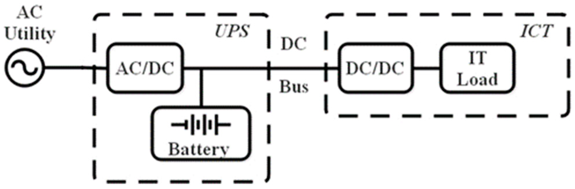
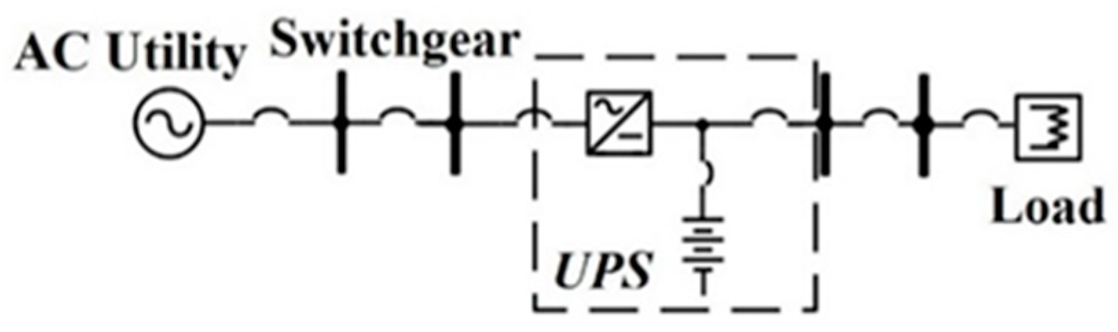
Among the many types of DC distribution systems, [18] introduced a selection of DC power distribution for industrial applications, as shown in Figure 1. In conventional DC power distribution systems, which are widely used in applications such as data centers, the input energy from a utility undergoes power conversion before being supplied to the information and communication technology (ICT) system or other energy-consuming equipment in the system, while high-cost backup power supplies, such as batteries, must be employed to respond to possible interruptions that may occur in the data center and achieve higher reliability.
Reliability is an important characteristic that describes the performance of a power system under certain conditions for a defined period [19,20]. Additionally, reliability indicates how frequently the system fails, since the servers of data centers operate in critical situations with low tolerance of interruptions and breakdowns. Therefore, maintaining a high level of reliability is essential. Interruptions and failures that occur in data center power systems can have significant cost, up to millions of dollars per hour [20]; therefore, the downtime of distribution systems must be reduced as much as possible.
Recently, the triple active bridge (TAB) converter has shown feasibility for application in distributed renewable power systems to improve the interaction of multiple DC links from the network systems to the loads [21]. In [22], the use of an isolated H-bridge TAB converter obtained high-efficiency voltage conversions and high-power capacity. A TAB converter with high-frequency magnetic coupled H-bridge cells, and high power transmission ability, was proposed in [23], which described the advantages of a TAB converter with an isolation function configuration for power distribution. Additionally, a power flow control system for the TAB converter was developed using decoupled phase-shift control, and the efficiency of a TAB converter prototype using a GaN power device reached 97.6% [24]. In [25], a TAB converter prototype using an SiC power device (rated at 400 V, 10 kW, and 20 kHz) was introduced to control the power flow in the power distribution system; the resulting waveforms showed that the TAB converter reacted to the power flow control quickly, and demonstrated the feasibility of building DC microgrid systems with multiple TAB converters.
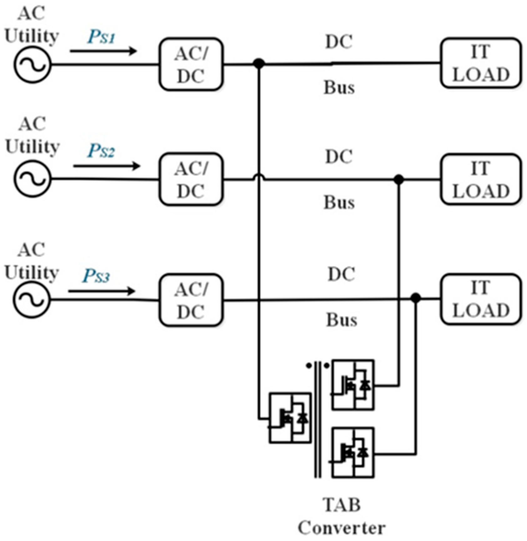
This paper proposes a DC power distribution system with a TAB converter for a data center and the associated power management scheme, as shown in Figure 2. The system can contribute to the good performance of power distribution, and can achieve high reliability compared with conventional systems, as shown in Figure 1. The power management system, which uses phase-shift control, can distribute power among the distribution lines on demand, and can address the varying demands of load power in data centers to achieve load balancing. In Section 2, the foundation and the concept of the TAB converter are introduced, and the model of a distributed system in a data center in a DC microgrid is presented. In Section 3, the power management scheme of the distributed system, which includes phase-shift control and power balancing control, is described. In Section 4, a simulation of the performance of the proposed distribution system in terms of power management is presented. The simulation results demonstrate the operation of the power management scheme for DC power distribution systems with varying power demands and the behavior of the proposed structure. In Section 5, the definition of reliability is provided, and the reliability of the proposed power distribution system is found to be superior to that of conventional DC power distribution systems.
2. Modeling of the Power Distribution System with the TAB Converter
2.1. Topology of the TAB Converter
Figure 3 shows the structure of a TAB DC–DC converter circuit that can satisfy triple-directional energy flow requirements in power distribution systems. The circuit consists of three active H-bridge cells that are coupled with a three-winding high-frequency transformer. The primary, secondary, and tertiary ports can be connected to DC sources, such as batteries.
Theoretically, the circuit of the TAB converter can be regarded as a grid of inductances (including the magnetizing inductance of the transformer, leakage inductance, and external inductance). Each full-bridge cell operates at a certain switching frequency and is fixed at 50% of the duty cycle. The power flow among ports and sources can be controlled by phase-shifting the switches in the full-bridge cells. In the converter model, fsw represents the switching frequency, and Le1, Le2, and Le3 denote the inductances that are connected to the different ports, whereas V1, V2, and V3 are the input DC sources connected to the primary, secondary, and tertiary sides, respectively.
2.2. Modeling of the Power Distribution System with the TAB Converter
Figure 2 shows the proposed power distribution system with the TAB converter, which is connected to a DC input source and resistive loads in a data center. The resistive loads at the ends of the power distribution system represent information technology (IT) loads, such as servers and other ICT equipment, while the sources VDC supply input power for each load. During the normal operation of the data center, the input DC source transmits power to the loads from the input sources.
In the power distribution system, the TAB converter is employed as a power router. Under situations of increasing and decreasing demand of resistive loads, or under full-load and half-load operation in the data center, DC transmission between the power racks is necessary. By using the TAB converter and power flow control, power balancing can be achieved in the operation of the DC power supply.
3. Power Management for the Proposed Distributed System
This study focuses on power management for the proposed power distribution system, which controls the power from the supply to the loads in a DC microgrid distributed system. The objective of this power management scheme is to supervise the power flows among the distributed lines and resolve unbalanced power situations in the DC distributed system.
3.1. Phase-Shift Control of the TAB Converter
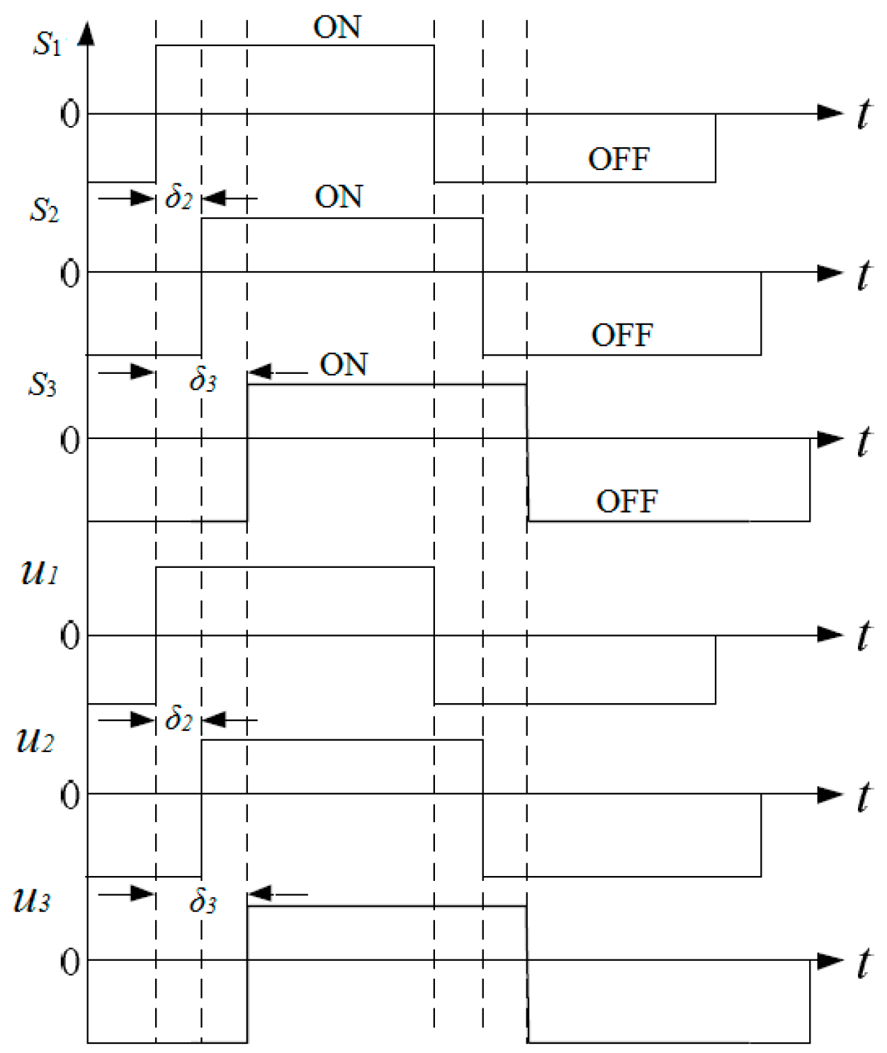
Figure 4 shows the phase-shift pattern and voltage waveforms (u1, u2, and u3) in each port on the sides of the transformer under phase-shift control. Considering the phase shift of the full-bridge cell of the primary side as the reference value, the phase-shift angle of the control signals between the primary and secondary sides is described as δ2 [rad], whereas the phase-shift angle of the switch signal between the primary and tertiary sides is described as δ3 [rad].
For the same input voltage, equal voltages V1, V2, and V3, and equal inductances at the three ports Le1, Le2, and Le3, the relationship between the power flow and the phase-shift angle can be expressed by the following simplified equations [26]:
As described in Equation (1), power transfer in the TAB converter is possible in three directions between any ports, and the amplitude of the distributed power is only determined by the variables δ2 and δ3; thus, accurate power flow control is obtained. In the design of the parameters of the TAB converter, when the DC input source and the power flows are selected, the phase shift can be calculated based on the phase shifts δ2 and δ3, and is in the recommended range of 0–0.5236 [rad] [26]. Normally, the inductance and the power flows of the TAB converter can be controlled only by the phase-shift angle.
3.2. Load Balancing Control
A typical power distribution system in a large-scale data center has several loads working independently and far from each other. Each load has different power requirements and varying processing capacity. For robustness and sustainability, requests from loads are equally and effectively distributed in parallel. To achieve high reliability and conserve energy between the application load and the input sources, the power balancing control distributes the load demands across the input resources and balances the power in the loads.
We propose a load balancing control that can analyze the power demands of the loads by evaluating the power distribution in each rack. Thus, the power in the power distribution system can be saved, and the responsiveness and reliability of the system are improved. The power balancing of the three racks in the DC power distribution system is based on the equations below:
where represents the balanced power flow in each line after the application of power balancing, and is determined by the power from the input sources PS1, PS2, and PS3. After analyzing the power from the load side, PR1, PR2, and PR3, and the balanced power in each line, , the reference power and at each port of the TAB converter is selected. From Equation (2), it is obvious that the power transmitted in the TAB converter is controlled by the real-time load power and the input power at each power rack. Therefore, by using the load balancing control, the input power of the DC power distribution system can be balanced, while the TAB converter can transmit power between the power racks by using phase-shift control. We propose a power flow control method, which is shown in Figure 5, and consists of the closed-loop phase-shift control and the load balancing control. When the load power in the terminal of the DC power distribution system is varied during full-load or half-load operation, the load balancing control scheme detects the power demand and gives a command to the TAB converter; thus, the power transmission in the power distribution system is adjusted accordingly, with the help of the TAB converter.
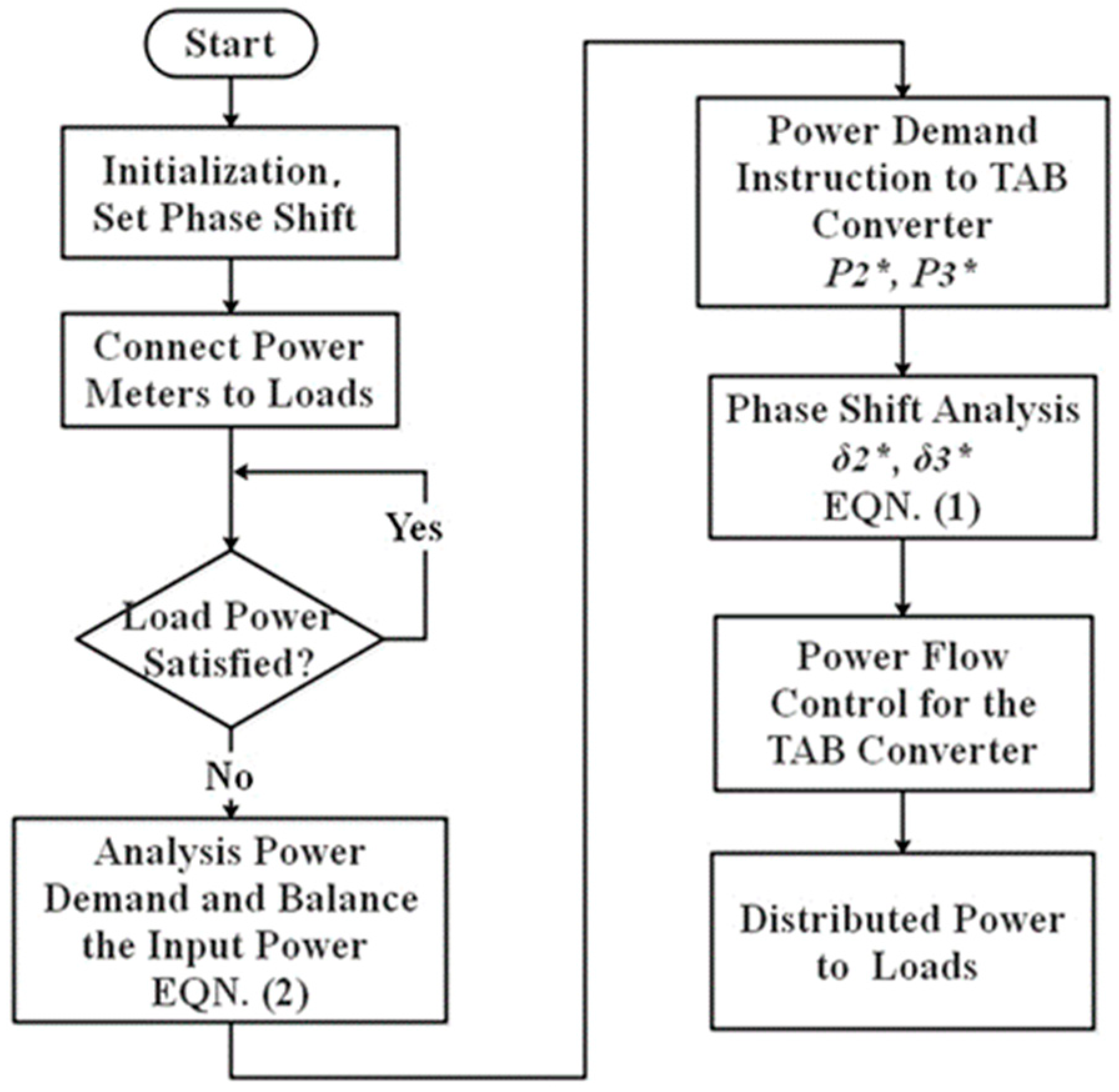
A flow chart describing the methodology applied in the proposed system is shown in Figure 6. When the power distribution system is started, the initial phase shift is set in the TAB converter. Then, using the power meters in the data center power distribution system, the power demands of the loads are analyzed, and the power flows among the three lines are balanced. Subsequently, the power references for the TAB converter are calculated using phase-shift analysis, and the TAB converter follows the instructions of the power flow control. Thus, the power transmission is completed, and the power demands of the loads are satisfied.
4. Power Management Simulation
4.1. Simulation Setup
To validate the power flow control for the DC power distribution system in the DC microgrid, simulations were conducted for the full-load and half-load conditions using a 380-V DC grid input. The Powersim simulation model of the power distribution system with the TAB converter was based on the diagram of Figure 2. The resistors at the end of the distribution system represent the resistive loads in a network system, such as servers or the IT load, which consume varying amounts of power according to demand. The phase-shift control of the TAB converter was included in the simulation. The parameters of the 380-V TAB converter are shown in Table 1.
4.2. Simulation Results
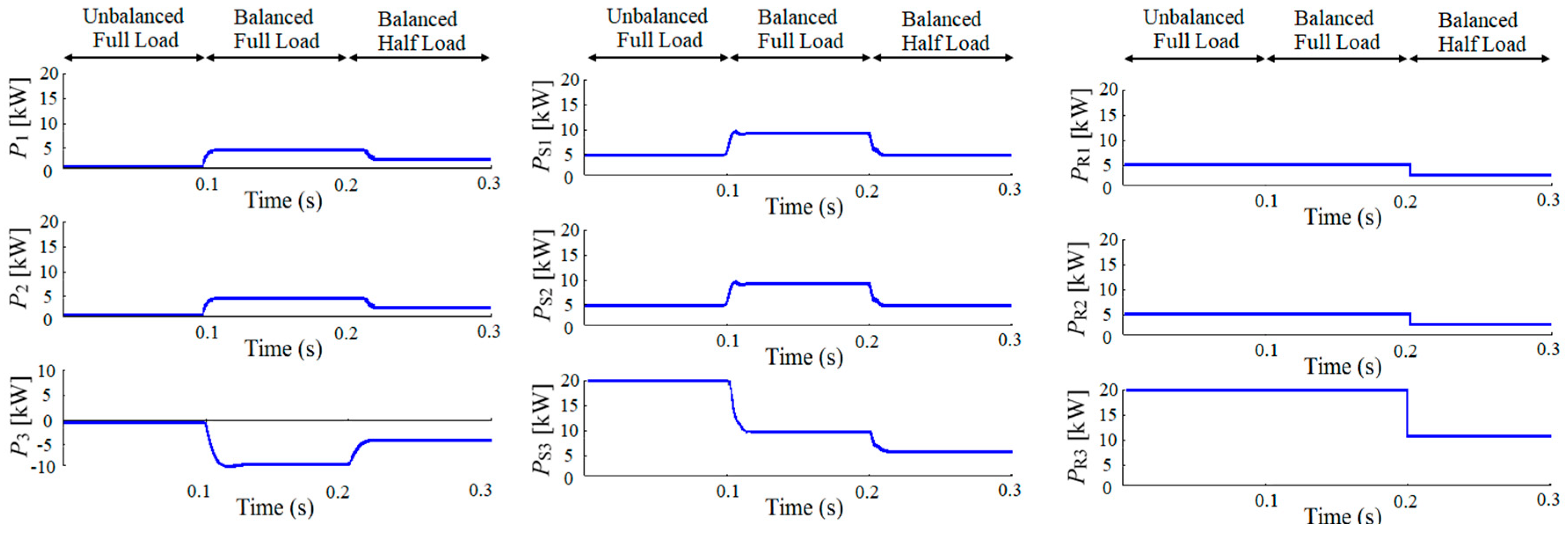
After designing the proposed DC power distribution system in the simulation using the conditions shown in Table 2, three periods were examined: an unbalanced (without the TAB converter) full-load period, a balanced (with the TAB converter operation) full-load period, and a balanced (with the TAB converter operation) half-load period (see Figure 7).
Figure 8 shows the simulation results. In the first period, the power distribution system operates under unbalanced full-load conditions, without using the TAB converter or power flow control. Owing to the different load powers, the input power flows PS1, PS2, and PS3 are under the unbalanced condition, delivering 5 kW, 5 kW, and 20 kW, respectively, to the resistive loads. In the second period, when load balancing control is applied and the TAB converter is used, the power flows PS1, PS2, and PS3 are adjusted to the same amplitude of 10 kW, ensuring balanced power in the power distribution system under balanced full-load operation. Meanwhile, each of PS1 and PS2 transmits 5 kW of power to PS3 through the TAB converter.
During the last period, when the power at the resistive loads is decreased to a half load, the power flows PS1, PS2, and PS3 are adjusted to an amplitude of 5 kW, while PS1 and PS2 transmit 2.5 kW of power to PS3 through the TAB converter, ensuring the transmission of half-power to PR3. The waveforms of the power flow in the racks of PS1, PS2, and PS3 are changed from the unbalanced to the balanced amplitude using the power flow control, and the power from the input source can be conserved when the load is decreased from full-load to half-load. Further, from the waveforms of PR1, PR2, and PR3, it is clear that the load power required by the users is guaranteed during full-load and half-load operation.
In the operation of data center, using the TAB converter with a switching frequency of 15 kHz represents taking 66.67 μs each cycle; the information of changes and fluctuation happen in the load power side will be instantly delivered and analyzed to the phase-shift controller.
4.3. Discussion of the TAB Converter and Overall System Losses
In the simulation, the proposed power management scheme was tested under full-load, half-load, balanced, and unbalanced conditions. Additionally, in the practical design of power management for power distribution system applications, the analysis of losses in the TAB converter and the overall system should be considered. Ref. [22] reported that the performance of a TAB converter with power delivery under 5 kW is approximately 97%, which means that the loss caused by the TAB converter is 150 W, whereas the power loss of the overall power distribution system is only 1%. Therefore, this minor power loss is ignored in this section and in Figure 7.
Secondly, the transmission efficiency of the TAB converter [27] and the power loss analysis of the three-winding transformer [28] have been previously examined by the author, as discussed in Section 4.
In this paper, we mainly propose a structure for a highly reliable power distribution system using a TAB converter. In the future, power loss analysis of the overall system and further experiments will be conducted.
5. Reliability Assessment of Power Distribution System
5.1. Definition of the Reliability
Reliability is an indication of the operation status of a component or a system composed of components during a specified time. To analyze the reliability of a power distribution system during normal system operation, calculations involving the failure rate and other indexes are employed [27]. In reliability analysis, the following parameters are generally employed:
MTBF: mean time between failures. The MTBF, which is usually expressed in failures in a certain number of years or hours, provides statistical failure information in a system.
R(s): system reliability, which describes the probability of a system remaining in operation from time zero to time t.
t: operation time.
The relationship between the MTBF, the operation time, and the reliability is:
5.2. Reliability Block Diagram Analysis
The reliability block diagram (RBD) method is recommended as a practical approach to assessing the reliability of industrial and commercial power distribution systems using modeling [29]. By plotting the components of a system in a diagram, we can analyze the system’s reliability. Additionally, the RBD is easy to understand by customers and convenient for locating single components, especially during repair and maintenance. When estimating the reliability of a power distribution system configuration, the following calculations must be performed.
Generally, the two typical types of connection, series and parallel connections, are formed using two or more components, as shown in Figure 9a.
In the upper diagram of Figure 9a, the system is made of elements R1–Rn, and the systems function well only when all of the components function properly. If R(S) represents the total reliability of a system with n elements connected in series, then the overall reliability of a system connected in series can be easily calculated from the reliability of each component:
The second fundamental arrangement of system components is shown in the bottom diagram of Figure 9a. In this arrangement, the system fails only when all of the components fail.
Therefore, the reliability of a system connected in parallel can be expressed as:
In real power systems, the components are often mixed and consist of both series and parallel arrangements. For such systems, the reliability calculation is mainly based on the independent reliability of the series or parallel configurations, and the components are assumed to operate without interacting. Therefore, in complex systems with combinations of components, by combining blocks connected in series or in parallel into a single block, the reliability of this new block can be easily obtained using Equations (4) and (5).
For example, the complex system shown in Figure 9b is composed of components connected in parallel and in series. The reliability of such a combined system can be expressed as:
The analysis of the RBD provides an availability to construct the functional frame with multiple components according to the system, and shows that each component contributes to the failure or success of the overall system.
In the assessment of the reliability of complex RBD systems, manual calculation is unfeasible. Thus, in this assessment, a programming module was developed for the reliability analysis. As shown in Figure 10 and Figure 11, the RBD models of existing conventional DC power distributions systems and the proposed power distribution system were established using the N + N structure. After constructing the RBD, the reliability assessment of the two structures was conducted using the reliability parameters of components of industrial and commercial systems [30,31], which are shown in Table 3.
Both topologies were built and analyzed with the component reliability data shown in Table 3. The assessment was performed with the assumption of five-year operation, which corresponds to 43,800 h of continuous operation. According to the results shown in Table 4, the reliability of the conventional DC power distribution system in the set time is 88.455%, whereas that of the proposed DC power distribution system is 97.5258%—an improvement of 10.25%. Regarding practical operation in large-scale data centers, the application of the proposed power distribution system would reduce downtime remarkably, by 794.602 h, as shown in Table 4. Additionally, with the proposed system, the bulky and costly battery could be reduced in the DC microgrid and TAB converter, thus improving the performance and budget of the data center power distribution system.
6. Conclusions
This paper proposed a DC distributed system using a TAB converter in a DC microgrid for realizing a high-reliability data center. The use of phase-shift control and load balancing control in the power management of the DC power distribution system was investigated. Simulations of the power distribution function were conducted considering full-load and half-load conditions during operation in a data center. The simulation results showed that the proposed model behaved controllably under the power management scheme. Moreover, the reliability analysis proved that the proposed DC power distribution system can achieve higher reliability than the conventional DC power distribution system, showing the advantages of robustness and low cost.
The satisfactory performance in the simulations validated the feasibility of applying the power control scheme in the DC power distribution system with the TAB converter, and proved that the proposed system and its power management can provide good performance and high reliability in the data centers in the DC microgrid. Future work will include accurate power control and adaptation experiments in data centers.
Author Contributions
Y.Y. built the system, designed the control methodology, performed the simulation, analyzed the reliability analysis, and wrote the paper; K.W. supervised the design, analysis, simulation and the paper.
Funding
This research received no external funding.
Conflicts of Interest
The authors declare no conflict of interest.
References
- Hernandez, L. A survey on electric power demand forecasting: Future trends in smart grids microgrids and smart buildings. IEEE Commun. Surv. Tutor. 2014, 16, 1460–1495. [Google Scholar] [CrossRef]
- Caramanis, M.; Ntakou, E.; Hogan, W.W.; Chakrabortty, A.; Schoene, J. Co-Optimization of Power and Reserves in Dynamic T&D Power Markets With Nondispatchable Renewable Generation and Distributed Energy Resources. Proc. IEEE 2016, 104, 807–836. [Google Scholar]
- Lu, S.; Wang, L.; Lo, T.; Prokhorov, A.V. Integration of Wind Power and Wave Power Generation Systems Using a DC Microgrid. IEEE Trans. Ind. Appl. 2014, 51, 2753–2761. [Google Scholar] [CrossRef]
- Eghtedarpour, N.; Farjah, E. Distributed charge/discharge control of energy storages in a renewable-energy-based DC micro-grid. IET Renew. Power Gener. 2014, 8, 45–57. [Google Scholar] [CrossRef]
- Dragičević, T.; Lu, X.; Vasquez, J.C.; Guerrero, J.M. DC Microgrids—Part II: A Review of Power Architectures, Applications, and Standardization Issues. IEEE Trans. Power Electron. 2016, 31, 3528–3549. [Google Scholar] [CrossRef] [Green Version]
- Patterson, T. DC come home: DC microgrids and the birth of the enemet. IEEE Power Energy Mag. 2012, 10, 60–69. [Google Scholar] [CrossRef]
- Barklund, E.; Pogaku, N.; Prodanovic, M. Energy management in autonomous microgrid using stability-constrained droop control of inverters. IEEE Trans. Power Electron. 2008, 23, 2346–2352. [Google Scholar] [CrossRef]
- Elsayed, A.T.; Mohamed, A.A.; Mohammed, O.A. DC microgrids and distribution systems: An overview. Electr. Power Syst. Res. 2015, 119, 407–417. [Google Scholar] [CrossRef]
- Becker, D.; Sonnenberg, B. DC microgrids in buildings and data centers. In Proceedings of the IEEE 33rd International Telecommunications Energy Conference (INTELEC), Amsterdam, The Netherlands, 9–13 October 2011. [Google Scholar]
- Liu, B. System operation and energy management of a renewable energy-based DC micro-grid for high penetration depth application. IEEE Trans. Smart Grid 2015, 6, 1147–1155. [Google Scholar] [CrossRef]
- Mei, Q.; Xu, Z.L.; Wu, W.Y. A novel multi-port dc-dc converter for hybrid renewable energy distributed generation systems connected to power grid. In Proceedings of the 2008 IEEE International Conference on Industrial Technology, Chengdu, China, 26 August 2008. [Google Scholar]
- Xu, H.G.; He, J.P.; Qin, Y.; Li, Y.H. Energy management and control strategy for dc micro-grid in data center. In Proceedings of the 2012 China International Conference on Electricity Distribution, Shanghai, China, 10–14 September 2012. [Google Scholar]
- Kumar, M.; Srivastava, S.C.; Singh, S.N. Control strategies of a dc microgrid for grid connected and islanded operations. IEEE Trans. Smart Grid 2015, 7, 1588–1601. [Google Scholar] [CrossRef]
- Wang, H.; Huang, J.; Lin, X.; Mohsenian-Rad, H. Exploring smart grid and data center interactions for electric power load balancing. ACM SIGMETRICS Perform. Eval. Rev. 2013, 41, 89–94. [Google Scholar] [CrossRef]
- Chen, W.; Wu, X.; Yao, L.; Jiang, W.; Hu, R. A step-up resonant converter for grid-connected renewable energy sources. IEEE Trans. Power Electron. 2015, 30, 3017–3029. [Google Scholar] [CrossRef]
- Mu, Q.; Liang, J.; Li, Y.; Zhou, X. Power flow control devices in DC grids. In Proceedings of the 2012 IEEE Power and Energy Society General Meeting, San Diego, CA, USA, 22–26 July 2012. [Google Scholar]
- Deng, F.; Chen, Z. Control of improved full-bridge three-level DC/DC converter for wind turbines in a DC grid. IEEE Trans. Power Electron. 2013, 28, 314–324. [Google Scholar] [CrossRef]
- Udagawa, Y.; Matsuo, H. Power Supply Technology and Air Conditioning Technology for ICT. NTT Technical Review. Available online: https://www.ntt-review.jp/archive/ntttechnical.php?contents=ntr201411fa10.html (accessed on 31 July 2018).
- Arno, R.; Friedl, A.; Gross, P.; Schuerger, R.J. Reliability of data centers by tier classification. IEEE Trans. Ind. Appl. 2012, 48, 777–783. [Google Scholar] [CrossRef]
- Wiboonrat, M. An empirical study on data center system failure diagnosis. In Proceedings of the 3rd International Conference on Internet Monitoring and Protection, IEEE Computer Society, Washington, DC, USA, 29 June–5 July 2008. [Google Scholar]
- Katagiri, K. Power flow control of triple active bridge converter equipped with AC/DC converter for constructing autonomous hybrid AC/DC microgrid systems. In Proceedings of the 43rd Annual Conference of the IEEE Industrial Electronics Society (IECON), Beijing, China, 29 October–1 November 2017. [Google Scholar]
- Kado, Y.; Shichijo, D.; Wada, K.; Iwatsuki, K. Multiport power router and its impact on future smart grids. Radio Sci. 2016, 51, 1234–1246. [Google Scholar] [CrossRef]
- Yu, Y.; Masumoto, K.; Wada, K.; Kado, Y. A DC Power Distribution System in a Data Center using a Triple Active Bridge DC-DC Converter. IEEJ J. Ind. Appl. 2018, 7, 202–209. [Google Scholar] [CrossRef]
- Yu, Y.; Masumoto, K.; Wada, K.; Kado, Y. Power flow control of a triple active bridge DC-DC converter using GaN power devices for a low-voltage DC power distribution system. In Proceedings of the IEEE 3rd International Future Energy Electronics Conference and ECCE Asia (IFEEC—ECCE Asia), Kaohsiung, Taiwan, 3–7 June 2017. [Google Scholar]
- Nishimoto, K.; Kado, Y.; Wada, K. Implementation of Decoupling Power Flow Control System in Triple Active Bridge Converter Rated at 400 V, 10 kW, and 20 kHz. IEEJ J. Ind. Appl. 2018, 7, 410–415. [Google Scholar]
- Zhao, C.; Round, S.D.; Kolar, J.W. An isolated three-port bidirectional DC-DC converter with decoupled power flow management. IEEE Trans. Power Electron. 2008, 23, 2443–2453. [Google Scholar] [CrossRef]
- Katagiri, K.; Nakagawa, S.; Kado, Y.; Wada, K. Analysis on Load-Factor Dependence of Triple Active Bridge Converter’s Transmission Efficiency for Autonomous Power Networks. In Proceedings of the IEEE Region 10 Conference, Penang, Malaysia, 5–8 November 2017. [Google Scholar]
- Nakahara, M.; Wada, K. Loss Analysis of Magnetic Components for a Solid-State-Transformer. IEEJ J. Ind. Appl. 2015, 4, 387–394. [Google Scholar] [CrossRef] [Green Version]
- Levitin, G.; Xing, L.; Ben-Haim, H.; Dai, Y. Reliability of series-parallel systems with random failure propagation time. IEEE Trans. Reliab. 2013, 62, 637–647. [Google Scholar] [CrossRef]
- Heising, C. IEEE Recommended Practice for the Design of Reliable Industrial and Commercial Power Systems, 1st ed.; IEEE Inc.: New York, NY, USA, 2007; ISBN 9781504431866. [Google Scholar]
- ANSI/VITA 51.1, “American National Standard for Reliability Prediction”, MIL-HDBK-217. Available online: https://snebulos.mit.edu/projects/reference/MIL-STD/MIL-HDBK-217F-Notice2.pdf (accessed on 31 July 2018).
Figure 1.
Diagram of conventional DC power distribution system in data centers.

Figure 2.
Diagram of a DC power distribution system in a data center using the triple active bridge (TAB) converter in a DC microgrid.
Figure 2.
Diagram of a DC power distribution system in a data center using the triple active bridge (TAB) converter in a DC microgrid.

Figure 3.
Topology of the TAB converter.

Figure 4.
Phase-shift patterns of the TAB converter.

Figure 5.
Diagram of power flow control in the power distribution system with the TAB converter.

Figure 6.
Methodology flow chart of power balancing and power flow control.

Figure 7.
Power flow diagram for the three simulation periods.
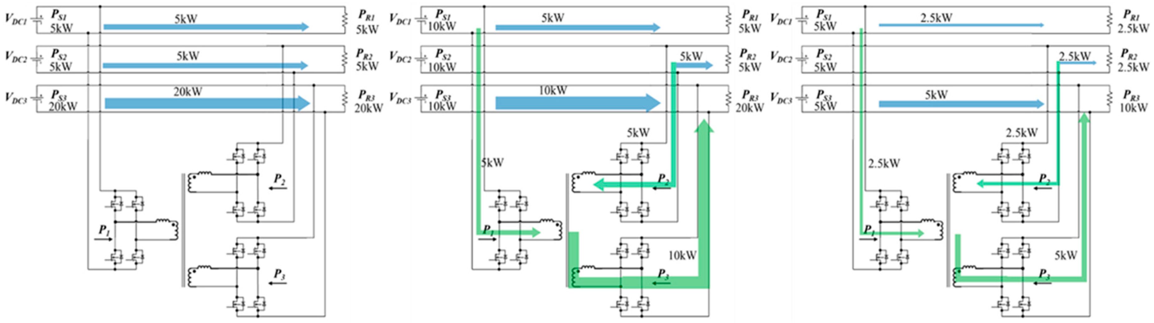
Figure 8.
Simulation results for the proposed power distribution system with the TAB converter and power flow control.
Figure 8.
Simulation results for the proposed power distribution system with the TAB converter and power flow control.

Figure 9.
Block diagram of connection types: (a) Series and parallel connection; (b) Combined connection.
Figure 9.
Block diagram of connection types: (a) Series and parallel connection; (b) Combined connection.

Figure 10.
Reliability model of a conventional DC power distribution system.

Figure 11.
Reliability model of the proposed DC power distribution system.


Table 1.
Parameters of the 380-V TAB converter used in the DC power distribution system.
| DC Voltage VDC | Switching Frequency | External Inductance | Transformer Leakage Inductance |
|---|---|---|---|
| 380 V | 15 kHz | 43.47 µH | 1.1 µH |
Table 2.
Simulation parameters for the 380-V TAB converter used in the DC power distribution system.
Table 2.
Simulation parameters for the 380-V TAB converter used in the DC power distribution system.
| Power Flow | Full Load without TAB | Full Load with TAB | Half Load with TAB |
|---|---|---|---|
| P1 | 0 | 5 kW | 2.5 kW |
| P2 | 0 | 5 kW | 2.5 kW |
| P3 | 0 | 10 kW | 5 kW |
| PS1 | 5 kW | 10 kW | 5 kW |
| PS2 | 5 kW | 10 kW | 5 kW |
| PS3 | 20 kW | 10 kW | 5 kW |
| PR1 | 5 kW | 5 kW | 2.5 kW |
| PR2 | 5 kW | 5 kW | 2.5 kW |
| PR3 | 20 kW | 20 kW | 10 kW |
Table 3.
Reliability parameters of electrical components used in industrial and commercial systems [30,31]. MTBF: mean time between failures.
| Component | MTBF (h) | Reliability (%) (within 5 Years) |
|---|---|---|
| AC utility supply | 99.9999 | |
| AC rectifier | 1,960,032 | 97.790126 |
| Inverter | 1,817,016 | 97.618276 |
| Lead Acid Battery | 1,173,590.3 | 83.318464 |
| Switchgear | 446,426.18 | 90.654689 |
Table 4.
Reliability comparison between a conventional power distribution system and the proposed power distribution system.
Table 4.
Reliability comparison between a conventional power distribution system and the proposed power distribution system.
| System | Reliability (% in 5 Years) | Downtime (Hours) |
|---|---|---|
| Conventional DC power distribution system | 88.455% | 1011.342 |
| Proposed power distribution system | 97.5258% | 216.73992 |
© 2018 by the authors. Licensee MDPI, Basel, Switzerland. This article is an open access article distributed under the terms and conditions of the Creative Commons Attribution (CC BY) license (http://creativecommons.org/licenses/by/4.0/).
Share and Cite
MDPI and ACS Style
Yu, Y.; Wada, K. Simulation Study of Power Management for a Highly Reliable Distribution System using a Triple Active Bridge Converter in a DC Microgrid. Energies 2018, 11, 3178. https://doi.org/10.3390/en11113178
AMA Style
Yu Y, Wada K. Simulation Study of Power Management for a Highly Reliable Distribution System using a Triple Active Bridge Converter in a DC Microgrid. Energies. 2018; 11(11):3178. https://doi.org/10.3390/en11113178
Chicago/Turabian StyleYu, Yue, and Keiji Wada. 2018. "Simulation Study of Power Management for a Highly Reliable Distribution System using a Triple Active Bridge Converter in a DC Microgrid" Energies 11, no. 11: 3178. https://doi.org/10.3390/en11113178
Note that from the first issue of 2016, this journal uses article numbers instead of page numbers. See further details here.