Article

Resilient and Immune by Design Microgrids Using Solid State Transformers

1
Faculty of Power Engineering, Politehnica University of Bucharest, 060042 Bucharest, Romania
2
Faculty of Sciences and Technology, Universidade NOVA de Lisboa, CTS-UNINOVA, 2829-516 Caparica, Portugal
3
Faculty of Electrical Engineering, Politehnica University of Bucharest, 060042 Bucharest, Romania
4
Polytechnic Institute of Setúbal, INESC-ID Lisboa, 2910-761 Setúbal, Portugal
5
KIOS Research and Innovation Center of Excellence, University of Cyprus, 2109 Nicosia, Cyprus
6
DNV-GL, 6812 AR Arnhem, The Netherlands
*
Author to whom correspondence should be addressed.
Energies 2018, 11(12), 3377; https://doi.org/10.3390/en11123377
Submission received: 1 November 2018 / Revised: 21 November 2018 / Accepted: 29 November 2018 / Published: 3 December 2018
(This article belongs to the Special Issue 100% Renewable Energy Transition: Pathways and Implementation)

Abstract

:
Solid State Transformers (SST) may become, in the near future, key technological enablers for decentralized energy supply systems. They have the potential to unleash new technologies and operation strategies of microgrids and prosumers to move faster towards a low carbon-based economy. This work proposes a paradigm change in the hierarchically and distributed operated power systems where SSTs are used to asynchronously connect the many small low voltage (LV) distribution networks, such as clusters of prosumers or LV microgrids, to the bulk power system. The need for asynchronously coupled microgrids requires a design that allows the LV system to operate independently from the bulk grid and to rely on its own control systems. The purpose of this new approach is to achieve immune and resilient by design configurations that allow maximizing the integration of Local Renewable Energy Resources (L-RES). The paper analyses from the stability point of view, through simplified numerical simulations, the way in which SST-interconnected microgrids can become immune to disturbances that occur in the bulk power system and how sudden changes in the microgrid can damp out at the Point of Common Coupling (PCC), thus achieving better reliability and predictability in both systems and enabling strong and healthy distributed energy storage systems (DESSs). Moreover, it is shown that in a fully inverter-based microgrid there is no need for mechanical or synthetic inertia to stabilize the microgrid during power unbalances. This happens because the electrostatic energy stored in the capacitors connected behind the SST inverter can be used for a brief time interval, until automation is activated to address the power unbalance for a longer term.

1. Introduction

Background

Today the power systems operate under the paradigm of bulk networks, synchronously interconnected over wide areas (e.g., the continental zone of ENTSO-E), where a disturbance that occurs at the highest voltage level can be experienced down to the low voltage level. In the 20th century, the electricity sector was driven by the expansion of long-distance transmission lines to allow power transmission from large power plants to any remote consumer. Under these conditions, wide area stability and control became the necessary coordination strategy in ensuring the quality of the electrical energy supplied to the customers [1]. With the advent of power electronics and IT&C technologies, the supply of electrical energy can be seen as a service [2], and the reliable operation of the grid is mandatory in ensuring the quality.
The microgrid concept was developed, similar to other smart grid concepts, as a solution for power system decentralization designed to enhance the controllability within local communities and to mitigate the technical problems that affect the synchronously interconnected power systems [3,4]. Microgrids are decentralized energy supply systems that could form the cells of a smart, adaptive and resilient power grid of the future [5]. Furthermore, microgrids are recognized as innovative environments able to maximize the integration of Local Renewable Energy Resources (L-RES) [6]. Their role is motivated by more and more stringent challenges on a global scale: climate change, economies in need for higher efficiency, resilience, sustainability of energy policies and capacity to mitigate disturbances in the energy supply [7]. However, the unpredictability of the power generation from RES is a barrier in advancing towards 100% clean energy [8], along with other aspects, such as reduced or no inertia, which is a consequence of higher share of power electronic converters mediated energy transfer (and less rotating generators) [9]. Moreover, there is also an increased need for addressing the power system resilience following the increasing frequency of occurrence of the natural or man-induced extreme phenomena [10]. In fact, resilience is one of the characteristics recognized as an essential value of the future energy grids [11] and the mission orientated goal for Europe is formulated as “A secure, efficient and digitalized European energy system, fully decarbonized by 2050, coupling all energy sectors.” [12].
In line with this latter challenge, DC medium and low voltage power distribution systems are also on the verge of research and development interests from both academia [13,14] and global industry players, such as Mitsubishi Electric or Siemens [15,16]. For instance, the distribution system operator from Finland carried out a feasibility study that concluded that low voltage DC (LVDC) electrical lines with lengths up to 8 km long can replace the existing AC infrastructure, with several advantages, among which, to increase the power transfer capacity up to 20% [17]. Other specialists concluded also that replacing medium voltage (MV) AC lines with DC lines can result in significant investment savings because of fewer induction transformers needed in the distribution grid [18]. Such vision is also a strong reason for deploying SSTs in future grid configurations, because they could easily allow access to a DC link.
A bottom-up development into an adaptive and resilient power system architecture implies a wide spread of low-voltage microgrids. A set of emerging technologies allows the implementation of multiple low-voltage microgrids, connected asynchronously with the main grid through SSTs. These technologies envisage distributed energy resources, especially renewables, and are derived from more recent trends in large adoption of storage (especially electrochemical type), while the core component for a seamless integration with the main grids is the solid-state transformer [19].
SST technology has been enabled by the advancements in power electronics. Power electronics got relevant importance in the energy domain especially for high voltage, when first High Voltage Direct Current (HVDC) lines were constructed, and Flexible Alternating Current Transmission Systems (FACTS) applications proved to be also needed especially in long distance power systems [20,21]. The development of renewables and lately of electrical vehicles brought the economy of scale and new technologies, such as Silicon Carbide (SIC) switching devices, thus enabling the integration of low cost and high-quality devices in their designs [22].
For more information about SST technologies and power electronics possible configurations the reader may consult [23] and a comprehensive state of the art literature review from [24].
Even if the SST technology is not yet on the market, recent projects report on SST being demonstrated in pre-commercial stages, which can advocate that the SSTs need only a final push to arrive on the market. In this respect, proven SST prototypes are already reported in the project “The Highly Efficient and Reliable Smart Transformer, a new Heart for the Electric Distribution System” (HEART) for smart grid applications developed by Kiel and Aalborg Universities [25], in ETH Zurich, application of SSTs is targeting locomotives and fast charging for electrical transportation [26], or from North Carolina State University [27] where the first target already achieved is fast charging and direct connection to (MV) networks. Furthermore, SST efficiencies of 97% and 98% are already reported in References [26,27], while in Reference [26] the SIC technology is particularly mentioned as one of the reasons for improvement. New enablers are a prerequisite for new paradigms. Some of the most important are indeed decentralized deployments of RES and distributed storage clustered in microgrids configurations. However, none of these works investigate an architecture where the SST could play a crucial role in providing stability for low inertia microgrids. They are rather application specific, either on traction systems or on fast charging capabilities.
Although the L-RES can contribute to supply the load during some time periods, one major drawback of RES is the intermittent behavior which requires additional solutions. This problem has been addressed until now through wide area balancing solutions [28].
The problem of matching the local generation and load are about to be solved, as the new storage technologies, especially based on Li-Ion batteries, are gaining momentum and the prices are in continuous decline [29]. The 129 MWh battery recently commissioned in Australia [30] and the plans for large new storage facilities in Hawaii [31] are only some of the many examples of battery applications used today at large scale.
In the case of microgrids, however, a usual approach for an islanded operation mode is possible only after disconnection from the main grid, which inevitably implies a short period of interruption, which can take a period from seconds to minutes. This is because the energy sources in microgrids are connected with anti-islanding protections required by the actual grid codes [32]. Also, it is because the inverter-based sources are designed to operate in a “grid following” mode, which means that they can be synchronized to the grid only if the frequency and its voltage are provided by an external part, which normally is the bulk grid.
The possibility of mitigating on short to medium term a match between production and consumption during the post-disconnection moment (when starting to work in islanding operation mode) are discussed in recent works [33]. In this case, the under investigation micro-grid was considering a diesel generator as a master in order to keep the stability of the microgrid while the photovoltaic (PV) and storage was in a grid or generator follower mode. However, in full inverter-based networks able to commute to island mode is not yet fully considered for most of today’s microgrids.
Moreover, there is yet an unclear technical solution to be pursued for microgrids in the case of high system stability threats, such as the case of inertia reduction in large power systems (due to reduced rotational inertia capable to inject or absorb energy), which may bring instability and even collapse during unbalance transients. The microgrids are facing, in most cases, zero rotational energy source inertia, as they may include only grid-follower inverters. Therefore, their stability problem is even worse in the case of emergency islanding from the main grid.
As a consequent drawback of these uncertainties, there is yet no “microgrid by design architecture” in place, to be used for mediating large quantities of renewables and resilience or even immunity for the grid end-users. The key vision of the paper is that the SST allows an asynchronous interconnection between the bulk power system and the many small low voltage (LV) distribution networks. This enables implementing local optimization strategies of the energy supply service while meeting the requirements for relying more and more on clean energy production at the local level. The purpose of this new approach is to achieve immune and resilient by design configurations that allow maximizing the integration of Local Renewable Energy Resources (L-RES). The need for asynchronously coupled microgrids requires a design that allows the LV system to operate independently from the bulk grid and rely on its own control systems. Therefore, all necessary design measures are to be taken, such as generation-load balancing, local demand-response, local energy markets or other similar energy services. Such a microgrid is not intended to have an installed generation capacity capable to fully cover the load, and thus the power difference can be supplied from the bulk power systems through the SST, which is the only point of connection of the microgrid to the bulk grid, based on an ex-ante schedule. Moreover, today electronics are capable to address complex equipment such as, SSTs in a more cost-effective way, thus allowing SST to become a standard equipment, which improves the microgrids functionality, surpassing the classic transformer through functionalities, which are not possible with traditional solutions, such as flexible coupling between the medium and the low voltage networks, possibility to enable an additional DC grid by design and other advantages to be developed in next section.
The main contributions of this work are summarized below:
  • Proposing a new architecture for interconnections between the main grid and the LV distribution grids by eliminating the need for synchronicity and by obtaining microgrids by design (always operating in island mode versus the main grid, which only injects a constant power in the SST DC busbar); it is shown that the architecture brings resilience and immunity by design in the microgrid;
  • Proposing suitable test cases for the evaluation of the proposed architecture in terms of microgrid stability, in a situation with power electronics-only energy injection and no classical mechanical inertia (no rotating machines to stabilize the grid); the test cases are also showing that the microgrid has resilience and immunity, which is supported by the proposed design;
  • Showing with the selected test cases that in microgrids with power electronics only generation, the microgrid stability is based on electrostatic energy in the capacitors behind the inverters. Thus, a different stability principle applies compared with the classical main grid mechanical-inertia dependent principle. This is the most important contribution, as in most of the studies one tries to keep an acceptable mechanical or mechanical-simulated inertia within the grid, in order to keep the frequency around the nominal value;
  • Summarizing the possible multiple roles of SSTs to ensure resilience, sustainability, adaptability and expandability of the architecture in a smart grid vision with SST separated LV microgrids.
The rest of this paper is organized as follows. In Section 2, the description of the new architectures based on SST enabled microgrids are presented. Section 3, describes the test-cases used for simulations, while Section 4 details the simulations, interpret and discusses the results, while the conclusive remarks are given in Section 5.

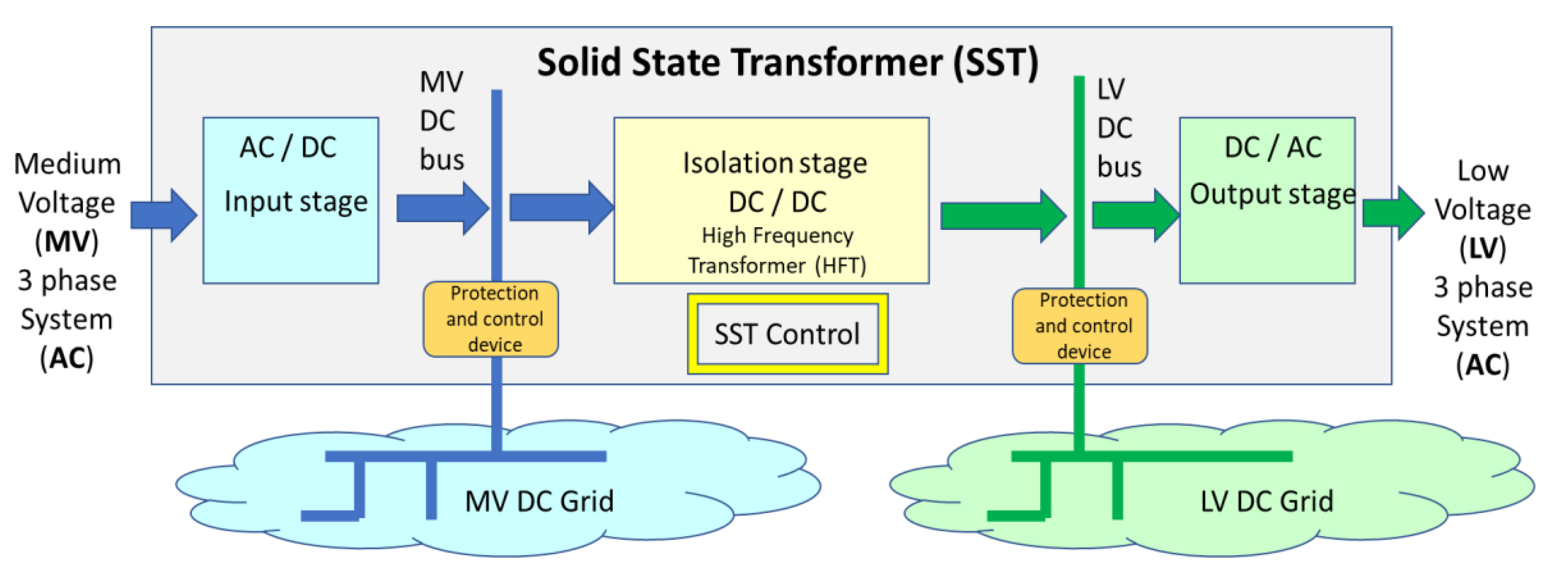
2. New Architectures Based on SST Connected Microgrids

Solid State Transformers (SSTs) or smart transformers are key technological enablers for several types of applications, such as traction systems, distribution electricity networks, including microgrids, storage deployment etc.). They have attracted significant attention during the last two decades, especially due to needs related to the smooth integration of RES into the main power grid [34]. SSTs are devices that use power electronics to ensure power flow from a voltage level (focus on MV) to another voltage level (focus on low voltage) by using high frequency transformer (HFT) coupling (e.g., 5 kHz to 50 kHz) instead of standard industrial frequency (50 or 60 Hz). Several topologies can be considered, going from single stage to multi stage or considering, or not, the existence of an intermediate DC bus. Being potentially highly modular, SST can be described using Power Electronics Building Blocks (PEBBs) as described in Reference [34].
The idea of using SSTs as an interface between the MV grid and a microgrid based on local RES generation is not new [35]. In Reference [36], one of the promoted features of this architecture was related to control capabilities of the power flow exchange. However, the stability of the microgrid under these architectures was not investigated.
The most feasible SST topology is the three-stage configuration, where both MV and LV DC-links available [37]. An adaptation of this type of architecture is presented in Figure 1.
Figure 1 shows that the HFT works between an MV DC bus and a LV DC bus, while the AC grid compatibility is solved with rectifiers (one direction, as shown in Figure 1, or bidirectional in general case, with the later not addressed in this paper) and three-phased inverters. The internal graphical representation of the three blocks is generic. The most feasible SST topology is the three-stage configuration, where both MV and LV DC-links available, and it can be implemented in different ways (e.g., the rectifier can be a more complex Vienna rectifier) and with different topologies (e.g., HFT can be mono or with three phases etc.). Even if the arrow demonstrating the power flow is monodirectional—which is a proposed situation which only allows the absorption of energy towards LV—as a friendly approach in the business as usual frame (the “sponge” model), a general design allows also bidirectional energy exchange. This particular SST architecture has, by nature, a MV DC bus and a LV DC bus. By adding suitable internal connection and protection devices and making available the DC buses, additional DC grids can be developed outside the SST, with minimal added complexity inside it. This architecture is presented in Figure 2.
Figure 2 shows that new DC grids can be deployed from an SST, starting from the internal DC buses (the one-way energy flow continues to be pursued, for keeping the business as usual consumption only power flow, for which the existing distribution grids have been designed). Thus, it provides the first steps in solving the “chicken-egg problem”, by making available both, the AC and the DC, connections on each voltage level.
A third natural extension is the provision of storage means connected at one or at both DC buses, as it can be observed in Figure 3.
Figure 3 depicts the potential to include storage connected at any of the two DC buses, however, as microgrids are essential for achieving resilience and large-scale integration of geographically distributed renewable energy sources, the first place for storage to be considered is at the LV side of the DC bus.
The architecture described in Figure 3 does not use the low voltage DC grid (but stays as an expandable feature). However, the microgrid can be supported by several features, which have been pointed before as challenges, such as:
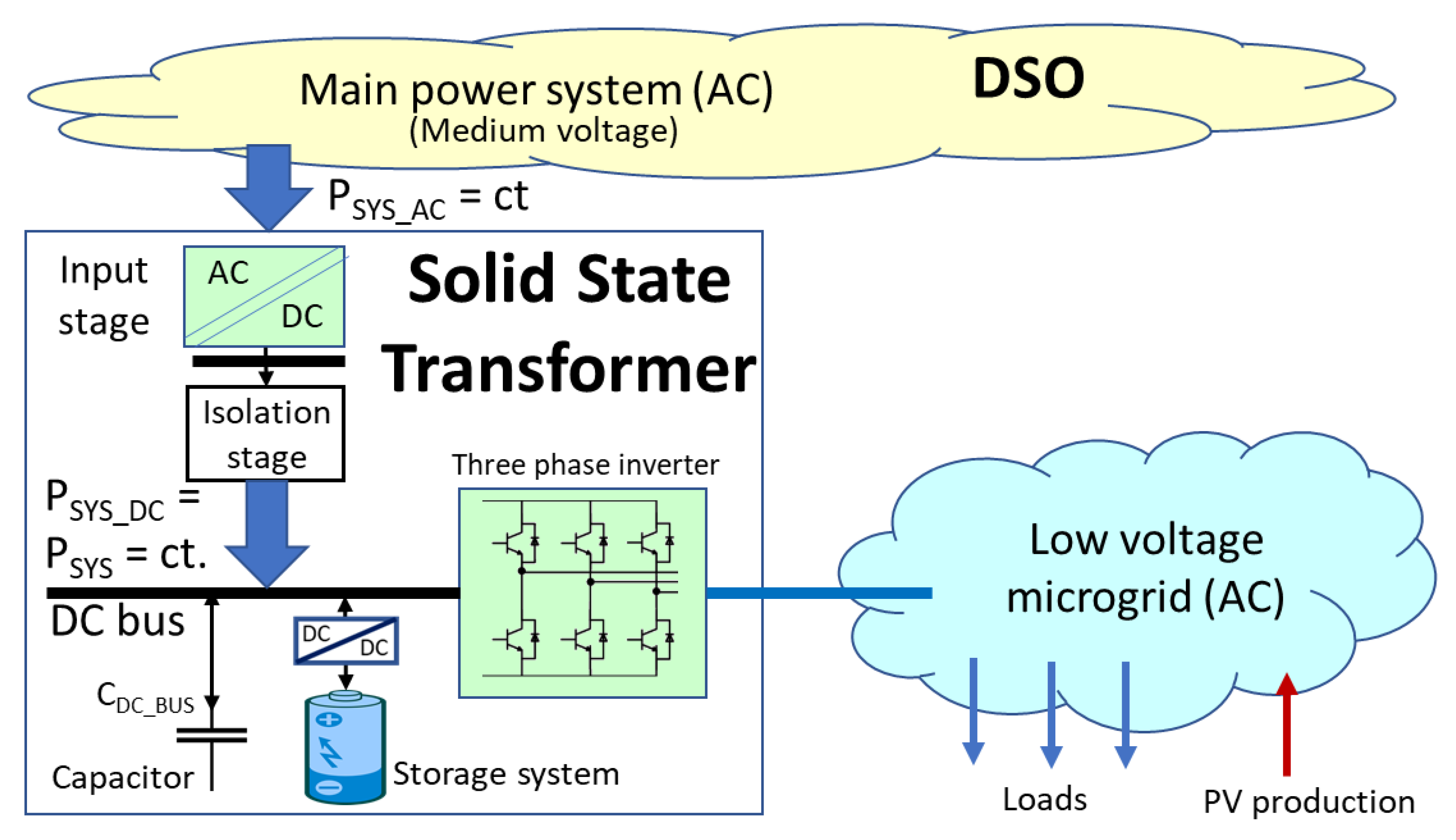
  • The balancing between the microgrid consumption and locally connected production (renewable, mainly PV) is now possible locally with the means of storage within the SST, acting as an equilibrium node of the whole microgrid;
  • The SST LV AC connection module can operate as grid forming device, thus giving the frequency and the nominal voltage signals, while all other RES can act in the standard grid-following mode;
  • Intense disturbances of the main grid cannot actually affect the microgrid, due to the SST AC/DC/AC interconnection. Further, intense variations, voltage sag events, low power quality in the main grid are smooth out by the SST and thus, the microgrid resilience and power quality can be enhanced (and it is decoupled from the resilience/quality of the main grid)
  • The connection with the main grid (MV network) becomes buffered, which can be translated into flexible, predictable and even constant power flow, thus drastically reducing the uncertainty in system operation (which may remain only on special cases), and asking for less ancillary services while improving the stability in the main grid;
  • The buffered energy in the SST (or associated with SST, as the battery can be physically outside SST, but logically integrated), allows setting different degrees of resilience and even immunity, as the microgrid may be able to supply energy to loads even in the case of main grid outages;
  • Finally, the microgrid becomes an independent system by design, being able to operate as an island (a system by itself, with its own balancing means and not depending on the main grid synchronicity) or connected (through a back-to-back elastic connection).
An important aspect remains if SST could provide, besides being a microgrid former, the local grid stability during unbalance transients, which is now missing in the traditional interconnection, and which is provided by the main grid. Numerical simulations, presented in Section 4, show that grid stability, based on mechanical inertia transformed in needed energy by decreasing or increasing the rotation speed, thus the system frequency, is not anymore necessary in a fully inverter-based small system. In the next chapter it is demonstrated that transient generation-load unbalance is covered by the inertia coming from electrostatic energy in the SST capacitors, thus bridging the gap between disturbance and the automated balance implemented by means, such as voltage source control or droop control. It shows that the main grid type of inertia is not a concern for microgrids and that these can achieve a stable operation based on voltage recovery level, by combining both natural (immediate, based on physics laws, as it is the mechanical inertia working in large grids) and artificial means.
The scenarios developed in the following Sections emphasize the value of power balancing in the microgrid, addressing the system stability under unbalanced disturbances, and the ability of not propagating disturbances from the main grid towards the microgrid and vice-versa.

3. Numerical Simulation Scenarios

Within this section we define meaningful design and operation scenarios to show the main advantages for both the main (external) grid and the SST connected microgrid. Simulation cases based on these scenarios will be then tested and discussed in the next section.
For the implementation of the simulation cases several control systems were employed, namely for the inverter of the smart-transformer, for the DC/DC converter of the storage system and for the inverter of the PV system. The smart-transformer inverter is controlled by means of a sliding mode controller associated with a voltage vectorial modulator (Figure 4a). This controller was implemented with the purpose to control the voltages (Vcf 123) of the LC filter capacitors (grid voltage). For the battery system, a cascade control was used, as shown in Figure 4c. Since the battery is used to keep the direct voltage stable, a PI regulator associated with this voltage (VCo) was used for the outer loop, whereas for the inner loop a hysteretic controller was used. The inverter of the PV system is also controlled by a cascaded system (Figure 4b). However, in this model, a voltage (PI type) controller was employed within the outer loop (to maintain the direct voltage of the inverter stable around its reference value), and a current controller (hysteretic type) was used in the inner loop (to inject three-phase currents in phase with the grid voltages).
As the DSOs and the TSO need planning and predictable operation when connecting prosumers and microgrids, there are needs for new models and operation features when promoting MG architectures. To help mitigating this situation, model considerations and desired operation features of the promoted microgrid (MG) architectures are summarized below:
  • The profile of the power absorbed by the microgrid from the main grid shall be either set and known in advance (contractually bind) or schedulable. Therefore, in the proposed scenarios, we assume a constant power injection from the DSO towards the microgrid (Pgrid = constant).
  • Microgrid operation is set to “island operation mode”. In other words, as long as the grid provides only scheduled power/energy, the real-time balancing of the MG is performed internally. Thus, the real-time power control remains essential and can to be done by means of one or more of the following resources:
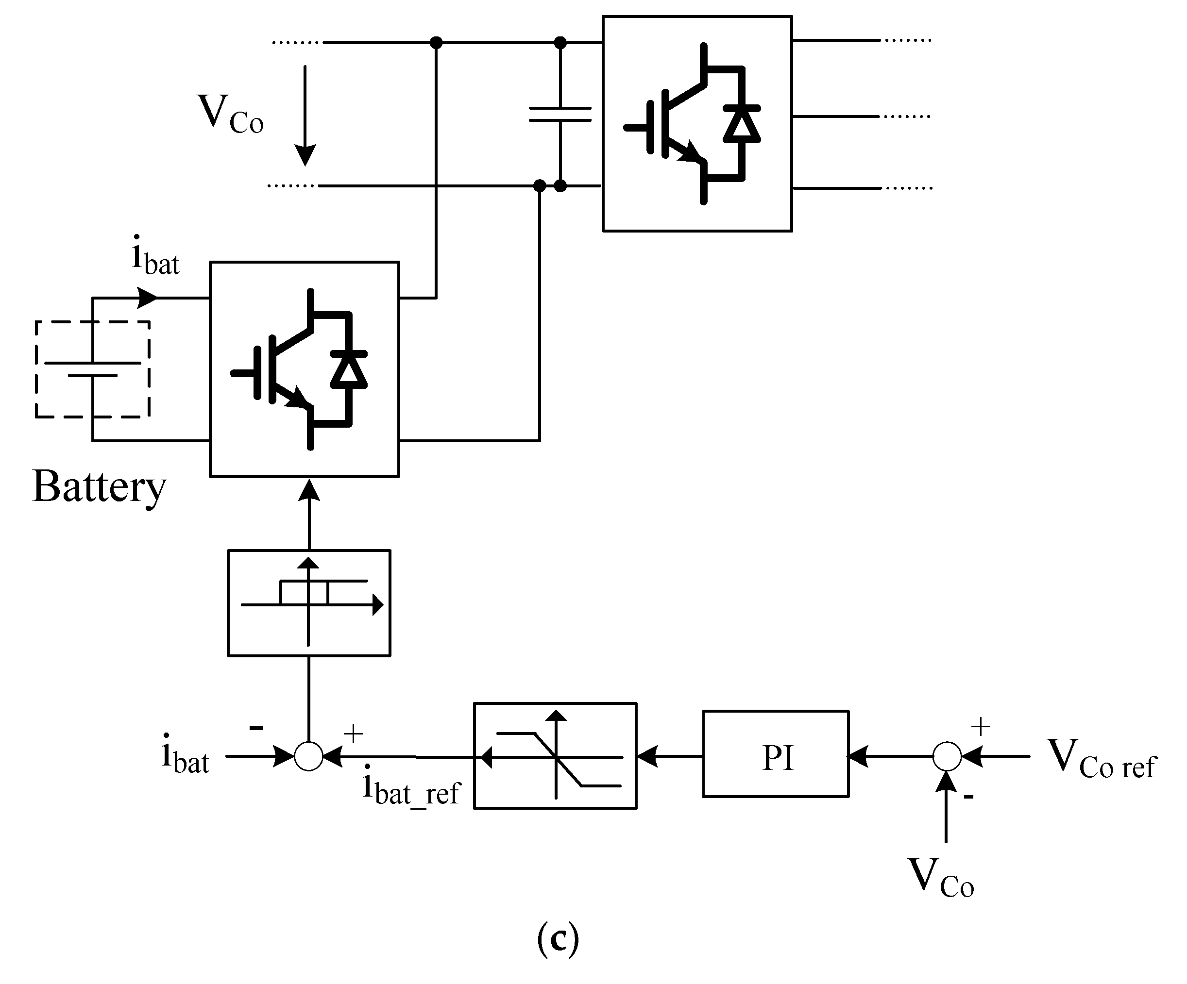
    storage units (e.g., battery) injects/absorbs power through the DC bus of the SST depending on the balancing needs of the SST (ΔP);
    LV inverter of the SST acts as grid former, which means that it provides the frequency signal and sets the operation point for the battery;
    in order to allow powers balancing, co-participation of PVs in the microgrid, in addition to its power modulation, the grid former can alter the frequency in a band centered on the nominal value (50 Hz) to allow primary control, in response to what the PVs can provide in real-time; note that all PVs operate in droop control mode. Therefore, frequency is only an information signal to show that a balancing reaction from the grid followers is needed (not anymore a physical consequence of unbalance, as it is in the main systems driven by large rotating machines), information that is easy to be spread over the whole microgrid through the same wires used for transmitting power.
The basic configuration of the SST, interfacing asynchronously (with back-to-back interconnection) the microgrid with the bulk power system, is presented in Figure 5.
Two use-case scenarios are defined based on the above-mentioned assumptions.
Use case 1.
A power unbalance occurs inside the microgrid, caused by the variation of local generation (PVs) and/or by the microgrid load. The balancing is provided by the SST through the battery and the capacitor connected to the SST LV busbar, while the set point of the power exchanged between the microgrid and the DSO remains unchanged.
Use case 2.
A disturbance is assumed to occur on the DSO side, which affects the power exchanged between DSO and MG. The internal balancing mechanism of the MG provides the necessary balancing by using the same mechanisms, i.e., battery/storage plus distributed droop control. This case is assumed in our simulations as a sudden decrease in the power provided by the grid (DSO), i.e., 10 kW or ~25% of the requested/scheduled power, or even complete loss of power due to a DSO grid short interruption or due to a blackout. Such a short interruption is considered in use case 2.
Figure 6 shows the sequence of events simulated to test the propose the microgrid interconnection solution in both use-cases.
The unbalance simulated in the first use-case is performed by connecting then disconnecting a load (PLoad) at the time instants T1LOAD and T2LOAD, whereas in the second use-case the DSO disturbance is simulated by disconnecting then reconnecting the link with the DSO grid at the time instants T3GRID and T4GRID.

4. Simulations and Results

The purpose of this section is to show, by numerical simulations, the effectiveness of the SST-based microgrid interfacing proposed solution, as well as the win-win outcomes for both the microgrid actors and the DSO. A simple microgrid scheme, together with a SST/inverter configuration, was simulated in Matlab/Simulink (Figure 7). The main variables are also illustrated in the figure.
The operation of the storage unit is coordinated through an SST that plays the role of an energy router both internally (within the MG infrastructure) and externally (between the DSO and the MG). The interplay between SST and the storage unit is intended to supply the necessary power/energy to compensate any type of perturbation coming from inside the MG or external (e.g., coming from perturbations/fault propagations taking place upstream of the DSO).
Due to the complexity of the studied network, accurate simplified models were considered for the AC main grid, as well as for rectifier and DC/DC High Frequency Transformer inside the SST. Those components were modelled through a controlled DC current source, controlled in power mode which is the way that the smart-transformer is normally controlled. The remaining components of the smart-transformer were simulated in a more detailed way. This will allow for the study the dynamic behavior of the smart-transformer when there are perturbations on the main grid side and how to react in order to maintain the secondary side stable (microgrid side).
The SST has been modeled by the following components:
  • The SST DC bus and its associated capacitor;
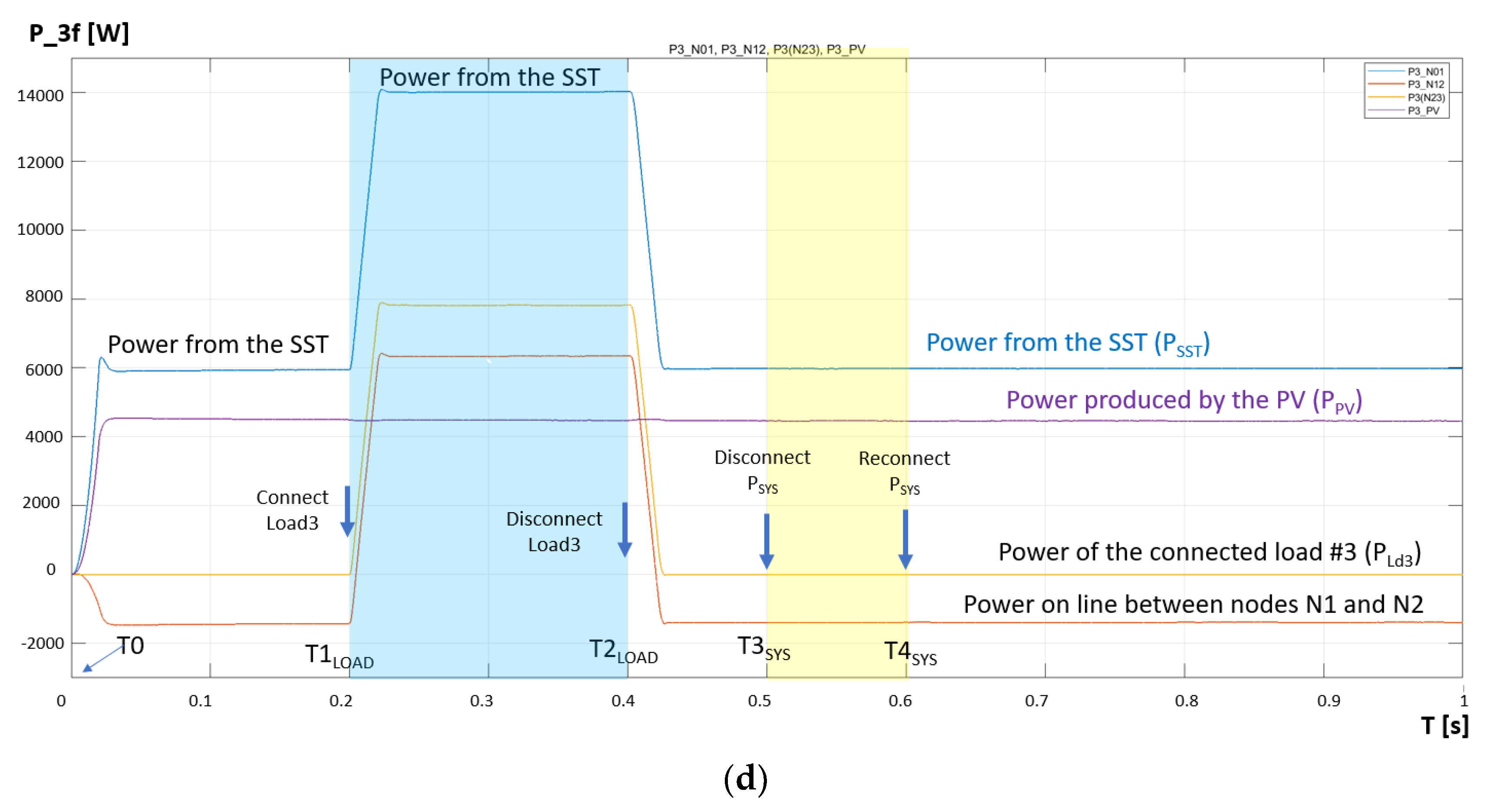
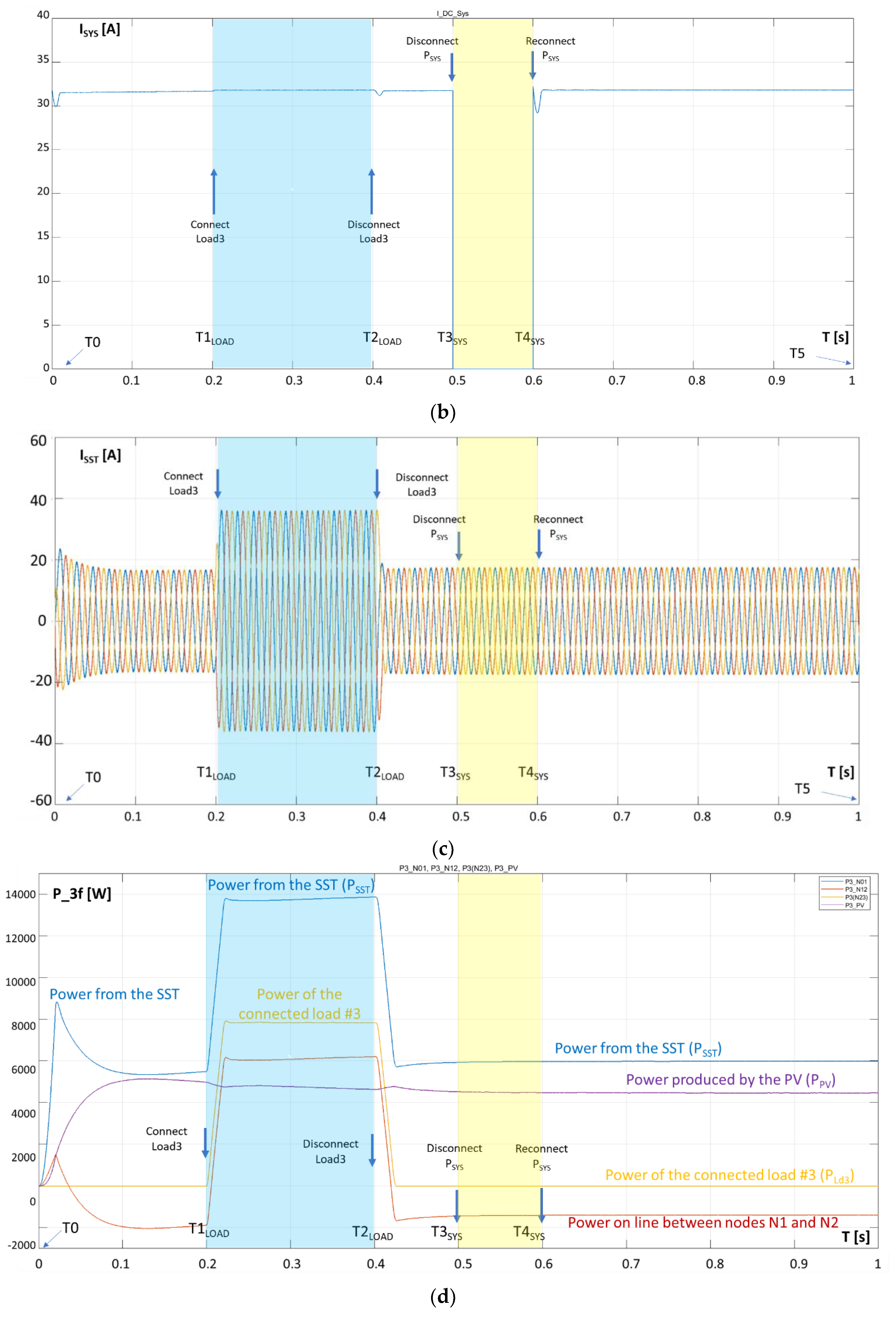
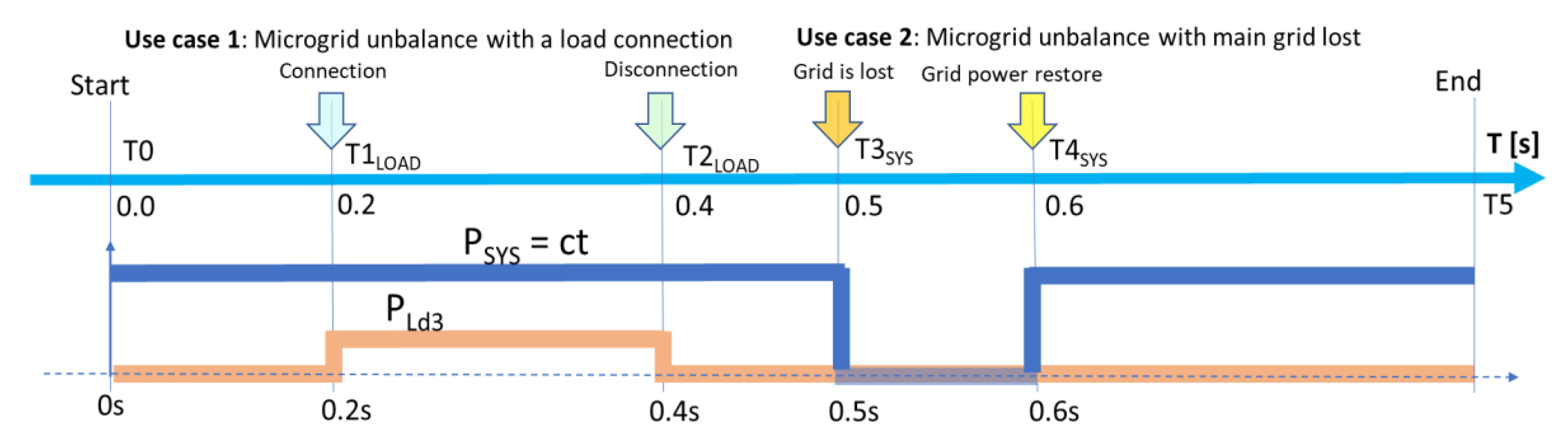
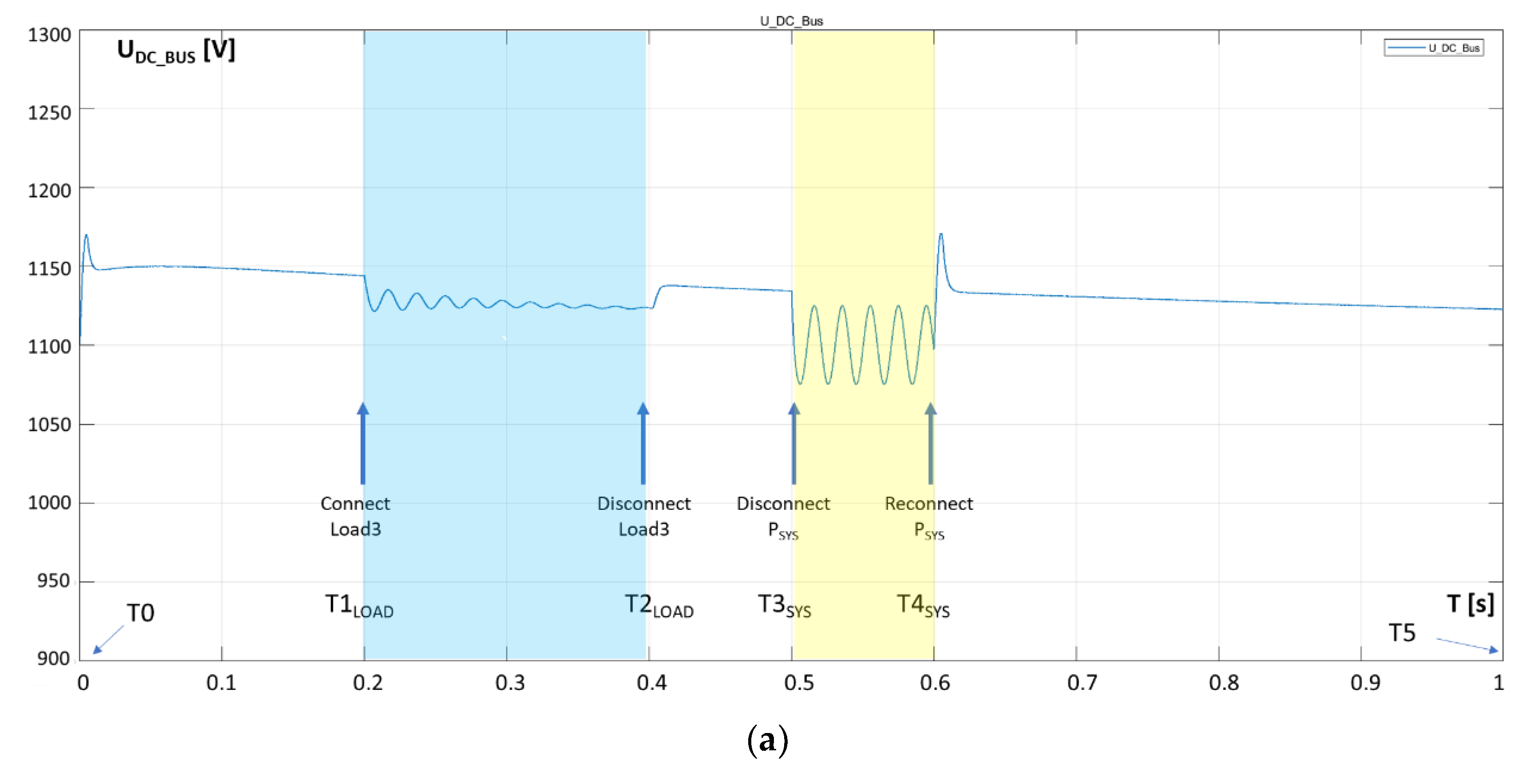
  • The DSO grid is modeled as a constant power source with PSYS = 35 kW, except the time interval [0.5s, 0.6s] when the loss the connection of the MG with main power system is simulated. PSYS is simulated as a power injection from the isolation stage of SST in the low voltage DC bus bar of SST, as per Figure 7;
  • One storage system (it can be also seen as a virtual aggregation of several storage units) connected to the SST DC bus through a DC/DC converter. The storage system is represented by a standard battery (model provided by the Simulink library), connected to the DC/DC converter. For the DC/DC converter, the classical bidirectional Buck/Boost converter was used [38]. The battery is also used to control the inner DC bus voltage, for which a PI controller was used. The time-response of the PI controller is defined by its variables kp and ki. The parameters of the battery are 725 V and 60 Ah;
  • An IGBT three-phase voltage source bridge inverter;
  • An LC low-pass filter, with LFlt = 5 mH (series) and CFlt = 10 μF (parallel), is employed on the AC side of the inverter to filter out higher frequency harmonics produced by the inverter.
The storage system is emulated with its internal capacitance and the time-response variables of its corresponding control system.
The scenarios are defined focusing on the DC bus capacitor and the parameters of the storage system PI controller. They are the most representative components of the simulated model in order to emphasize the model dynamics. Therefore, two scenarios are identified:
(a) The capacitor on the SST DC bus is CDC_BUS = 10 mF, and the parameters of the proportional-integral (PI) controller associated with the storage system are kp = 2 and ki = 10, respectively (these are corresponding to a relatively fast response to disturbances).
(b) The capacitor connected to the SST DC bus is much lower (CBAT = 1 mF), while the parameters of its PI controller are also slower (kp = 0.5 and ki = 0.5, respectively).
The microgrid components are:
  • Electrical lines: Line 1 (Ln1) has RLn1 = 0.4 Ω, LLn1 = 50 μH, Line 2 (Ln2) has RLn2 = 0.3 Ω, LLn2 = 50 μ H, Line 3 (Ln3) has RLn3 = 0.5 Ω, LLn3 = 50 μ H.
  • Loads: Load 1 has P1 = 3 × 2500 W, Q1 = 3 × 2000 var at nominal voltage U = 230 V AC; Load 2 has R2 = 50 Ω, L2 = 1 mH on each phase; Load 3 has P3 = 3 × 3000 W, Q3 = 3 × 2000 var at nominal voltage U = 230 V AC.
  • PV generation unit: It is connected in node 2, in parallel with load 2 and is generating a constant power of 3 × 1500 = 4500 W. Its characteristics have been extrapolated from a real PV system consisting of a set of Sunmodule Plus SW 300 mono PV panels [39] with a total power under STC conditions of 24.2 kW. The PV unit is connected to the microgrid via a classical three-phase inverter. This PV system was implemented in Matlab/Simulink trough the Simscape toolbox elements.
As presented above, the scenarios are defined with two different dimensioning and parameterizations in the SST (CDC_BUS and controller parameters), in order to show their importance in maintaining the microgrid stability in the case of the most severe perturbations, i.e., power unbalance inside the microgrid (use-case 1) and loss or power supply from the main grid outage (short term or blackouts as use-case 2). Note that this work does not focus also on short-circuit type disturbances because they need a more detailed analysis of the microgrid architecture and protection solutions. The scenarios capture the capability of the microgrid to achieve immunity and resilience against system disturbances and blackouts.
Scenario 1:
Use-cases 1 and 2 are tested with a favorable dynamic inside the SST, as both grid former and controller for the microgrid: A normal capacitor connected to the SST DC bus (C DC_BUS = 10 mF) and fast response of the SST DC bus controller (kp = 2 and ki = 10 for the PI controller).
The following sequence of events for the two use-cases is considered: (i) at time instant t = 0.2 s, Load3 (3 × (3 kW + j 2 kvar)) is connected; then, at time instant t = 0.4 s, Load3 is disconnected; (ii) at time instant t = 0.5 s the power supply from the main grid is lost (PSYS = 0,), then at time instant t = 0.6 s the grid supply is restored to the scheduled value (PSYS = 35 kW). The results of this simulation are presented in Figure 8a–d.
As mentioned before, the power supplied by the main grid is maintained constant, and equal to a scheduled value. After the first perturbation (T1LOAD = 0.2 s), the power required by the loads is higher (a new load is connected, Load3). When the second perturbation occurs (T3GRID = 0.5 s), the power supplied by the grid is completely lost (unscheduled perturbance at the grid side, see Figure 7b). In both cases the battery will provide all the needed energy (instant power) required by the microgrid, with minimum or no intervention in load reduction.
Analyzing the AC currents injected by the SST (see Figure 8c), we can see that there is only a slight change in the amplitude of the load currents, which shows that in the case of a grid outage, the microgrid is capable of maintaining its normal operation and to ensure the power balancing without any need for load shedding (the current amplitude remains almost unchanged because the battery provides the required support).
Figure 8d illustrates the power flows in different sections of the microgrid. It can be seen that between T3GRID = 0.5 s and T4GRID = 0.6 s there is no observable power flow difference, as SST is taking the role to cover the missing PSYS during this outage, showing immunity during the period when the main grid is lost.
Scenario 2:
Use-cases 1 and 2 are tested with a smaller capacitance connected to the SST DC bus (CDC_BUS = 1 mF) and fast response of the PI controller (kp = 0.5 and ki = 0.5, respectively).
This test case is similar to the previous one with the only exception that the capacitance of the storage unit is ten times smaller. The results are presented in Figure 9a–d.
As it can be noticed, the results of this use-case look pretty much the same as in the previous case. These simulations show also the high level of immunity inherited by the microgrid within the proposed solution. The microgrid achieves stable operation after transient disturbances. The difference from Scenario 1 consists is in the inertia of the system based on the energy in the SST capacitor, influencing the amplitude transients of DC voltage on the SST capacitor following the perturbations, which is higher (as expected, since the capacity of the capacitor is smaller). To emphasize the difference between the two scenarios, the voltage resulted on the DC bus of the SST is shown in Figure 10. The blue zone is the DC voltage variation resulted from the disturbance caused by Load3, whereas the yellow zone is the DC voltage variation resulted from the loss of the main grid supply.
In this figure it can be seen that in Scenario 1, besides the time delay due to storage response, there is also a time delay from the physical part of the power converter that is much faster than the one caused by the controller of the storage. In fact, when there is a sudden change in the reference the rate-of-change-of-current is limited by the inductor inside the storage device. Note that the power converter used for the simulations in this study consists of an inductor and two switches (the classical bidirectional buck-boost converter was used for operating the charging and discharging of the storage device). During that transition, the capacitor connected on the SST DC bus is the component that must support the disturbance, while keeping an acceptable voltage variation until the storage unit control becomes effective. However, since the energy that is stored in this capacitor connected to the SST DC bus is small, then the voltage in the DC bus decreases slightly, as shown in Figure 9 with the blue line voltage evolution.
In the case of Scenario 2, the perturbation at SST DC bus level is higher. Therefore, it is easier to see the limitation effect of the grows in the rate of current. When there is a sudden transition, the battery current does not follow the reference, since its rate of growth is limited by the inductor, which affects more the voltage level on the SST DC bus. However, for the studied use-cases, the microgrid operation remains stable, showing the SST, as microgrid former, keeps well the microgrid stability during the disturbances.

5. Conclusions

The paper proposes an analysis, from the point of view of stability, of microgrid operation in the case of grid-connection via SST, which can be seen as an essential enabler of microgrids-by-design. This solution allows by design, the accommodation of large quantities of distributed renewables production, the friendly connection to the main grid (predictability and no disturbance propagation in both directions), while enhancing the resilience or even reaching immunity for the end-users supplied by the respective microgrid.
The advantages have been analyzed with two test scenarios, each with two types of disturbances in the microgrid—one considering the sudden connection of a load, and another one introduced by the sudden loss of a constant power supplied from the main grid. The simulations were performed in Matlab/Simulink version R2017b. A simplified microgrid was assumed, with only three loads (two modelled as constant real power P and modelled as constant impedance Z) and one PV plant assumed to produce constant power (PPV = ct.), all connected to a low voltage line, as depicted in Figure 7. The microgrid is connected to the bulk power system through an SST, consisting of the grid-connected inverter and the DC bus where the capacitor is connected, and the battery based storage system. The control of the SST output was also considered, namely through a cascaded controller in which the AC voltages (filter capacitors) and AC currents (inductor of the filter) are controlled. A controller for the PV system was also considered. In this case was again adopted a cascade structure, but what is controlled is the DC voltage of the inverter and their AC currents. The bulk power system is modeled as a power source that supplies a constant P to the DC bus-bar. Future work will consider more complex situations—requiring eventually for further elaboration of algorithms; however, the proof of concept has been demonstrated with the simplified grid. Moreover, future work will consider microgrid stabilization in wider time frames (minutes, hours or more), as being related to the battery and PV (microgrid local production) resources size in the microgrid.
The results of the numerical simulations consider a Decentralized Energy Supply System based on the SST connected microgrid which becomes immune and resilient towards power supply short failures and for blackouts. The simulation shows the level of resilience of the microgrid in this situation and the capacity to remain stable without mechanical inertia, but based on the electrostatic energy in capacitors behind the inverters, acting as system inertia to absorb the unbalance between loads and production. One important lesson is that the role of the mechanical inertia in the main grids is taken in the full inverter-based microgrid by the energy in the capacitors on the DC busbar behind the inverters, especially from the SST as grid former, and that the dimension of this capacitor needs to be chosen in order to cope with the disturbance level. In the studied microgrids, there is no frequency dependency for the grid stability, but only voltage control in the DC bus-bars of the injection points (SST and PVs injecting power in the microgrid used in our test cases), which allows to keep stability during the transients based on the released energy from the capacitors on the DC bus-bars behind the inverters. The two scenarios show that bigger capacitors give better stability of DC busbar voltage and of the microgrid, while smaller capacitors are still able to maintain stability against disturbances, even if the DC busbar voltage has a higher variation. We extend the simulation case studies: To address some variations regarding the PV generation, and also to examine how some disturbances for the grid side are observed in the microgrid side. In that way, we can claim that the main transient events that can occur in the daily operation of the microgrid have been adequately examined. These critical transient events are not a problem considering a wider time frame because in this case the stability of the system is only dependent on the battery and PV size.
Future work will expand the idea on the applicability and efficacity of shared resources for ad-hoc formed clusters of sub-microgrids connected physically or by cyber connection links. Moreover, more complex use-cases in terms of microgrid complexity and with more types of disturbances will be further analyzed, also by using new methods of enhancing its real-time balancing and stability.

Author Contributions

M.S. and J.F.M. are the main contributors of the paper, by understanding and refining the concepts and by demonstrating through simulations the stability of islanded microgrids with inverter-only energy sources connection, based on capacitors and storage means, with no need of frequency involvement. They are also main contributors for considering Solid State Transformers as essential devices in the microgrid-by-design architecture and for the resilience approach. I.C. contributed to the overall writing of the paper, on the simulations and analysis of results. M.A. contributed to the overall writing of the paper, with discussions on the subject and with the resilience approach. L.T. contributed to the overall writing of the paper, on the simulations and analysis of results. V.F.P. has contributed with the detailed simulation model based on real-time waves modeling, providing the essential tools for the analysis by simulation. L.H. contributed to the overall writing of the paper and with analysis against current microgrid approach. R.S. contributed to the overall writing, analysis and suggestions for improving the paper content. Conceptualization, M.S. and J.F.M.; Formal analysis, M.S., J.F.M., I.C., M.A., L.T. and L.H.; Investigation, M.S., I.C., M.A., V.F.P. and R.S.; Methodology, M.A.; Software, M.S., J.F.M., L.T. and V.F.P.; Validation, M.S., J.F.M., L.T. and V.F.P.; Writing—original draft, M.S.; Writing—review and editing, M.S., J.F.M., I.C., M.A., L.T., L.H. and R.S.

Funding

This work has been undertaken within the framework of the European Union’s Horizon 2020 research and innovation programme under the Storage4Grid project grant agreement No. 731155 and RESERVE project grant agreement No. 727481, by Portugal national funds through FCT—Fundacão para a Ciência e a Tecnologia, under projects UID/CEC/50021/2013 and UID/EEA/00066/2013, by DCNextEve project grant agreement No. 708844 and by KIOS CoE project grant agreement No. 739551.

Acknowledgments

Authors gratefully thank also to Professor Nicolae Golovanov for the vision of having SST as important new devices in the network, to Prof Emeritus Mircea Eremia for valuable discussions regarding the viability of the simulated microgrid, and to Prof. Goran Andersson, for valuable discussions on the overall subject. Prof Golovanov and Eremia are from Politehnica University of Bucharest, Romania and Prof. Andersson is from ETH Zurich, Switzerland.

Conflicts of Interest

The authors declare no conflicts of interest.

References

  1. Terzija, V.; Valverde, G.; Cai, D.; Regulski, P.; Madani, V.; Fitch, J.; Skok, S.; Begovic, M.M.; Phadke, A. Wide-Area Monitoring, Protection, and Control of Future Electric Power Networks. Proc. IEEE 2011, 99, 80–93. [Google Scholar] [CrossRef]
  2. Faruque, M.A.A.; Vatanparvar, K. Energy Management-as-a-Service Over Fog Computing Platform. IEEE Internet Things J. 2016, 3, 161–169. [Google Scholar] [CrossRef]
  3. Eremia, M.; Shahidehpour, M. (Eds.) Handbook of Electrical Power System Dynamics: Modeling, Stability, and Control; Power Engineering Series; Wiley & IEEE Press: New York, NY, USA, 2013. [Google Scholar]
  4. Hatziargyriou, N. MicroGrids; Wiley-IEEE Press: New York, NY, USA, 2014; ISBN 1-118-72067-9. [Google Scholar]
  5. El-Hawary, M.E. The Smart Grid—State-of-the-art and Future Trends. Electr. Power Compon. Syst. 2014, 42, 239–250. [Google Scholar] [CrossRef] [Green Version]
  6. Hirsch, A.; Parag, Y.; Guerrero, J. Microgrids: A review of technologies, key drivers, and outstanding issues. Renew. Sustain. Energy Rev. 2018, 90, 402–411. [Google Scholar] [CrossRef]
  7. European Climate Foundation. 2010. Available online: https://www.solarworld.de/en/home/ (accessed on 20 October 2018).
  8. International Renewable Energy Agency (IRENA). Renewable Energy Policies in a Time of Transition; IRENA: Bonn, Germany, 2018. [Google Scholar]
  9. Vandoorn, T.L.; Meersman, B.; Kooning, J.D.M.D.; Vandevelde, L. Directly-Coupled Synchronous Generators with Converter Behavior in Islanded Microgrids. IEEE Trans. Power Syst. 2012, 27, 1395–1406. [Google Scholar] [CrossRef]
  10. Ciornei, I.; Heracleous, C.; Kyriakou, M.; Eliades, D.; Constantinou, C.K.; Kyriakides, E. Test System for Mapping Interdependencies of Critical Infrastructures for Intelligent Management in Smart Cities. In Smart Cities in the Mediterranean; Progress in IS; Springer: Cham, Switzerland, 2017; pp. 355–377. ISBN 978-3-319-54557-8. [Google Scholar]
  11. Monti, A.; Huitema, G.; Sayed-Mouchawe, M.; Amezua, A.S.A. Digitalization of the Electricity System and Customer Participation; European Commission ETIP-SNET: Brussels, Belgium, 2018. [Google Scholar]
  12. European Technology and Innovation Platform for Smart Networks in Energy Transition ETIP SNET Decarbonizing Europe by 2050: EU Energy Players Propose One Broad Ambitious Mission for Europe. 2018. Available online: https://www.solarworld.de/en/home/ (accessed on 20 October 2018).
  13. Hailu, T.G.; Mackay, L.; Ramirez-Elizondo, L.M.; Ferreira, J.A. Voltage Weak DC Distribution Grids. Electr. Power Compon. Syst. 2017, 45, 1091–1105. [Google Scholar] [CrossRef] [Green Version]
  14. Gavriluta, C.; Caire, R.; Gomez-Exposito, A.; Hadjsaid, N. A Distributed Approach for OPF-Based Secondary Control of MTDC Systems. IEEE Trans. Smart Grid 2016. [Google Scholar] [CrossRef]
  15. Mitsubishi Electric Corporation. Mitsubishi Electric Launches D-Smiree System for Medium- and Low-Voltage DC Distribution; Mitsubishi Electric Corporation: Tokyo, Japan, 2016. [Google Scholar]
  16. Prötzsch, M. MVDC Plus. Available online: https://www.siemens.com/global/en/home/ products/energy/medium-voltage/solutions/mvdc.html (accessed on 5 March 2018).
  17. Hakala, T.; Lähdeaho, T.; Järventausta, P. Low-Voltage DC Distribution—Utilization Potential in a Large Distribution Network Company. IEEE Trans. Power Deliv. 2015, 30, 1694–1701. [Google Scholar] [CrossRef]
  18. Lassila, J.; Kaipia, T.; Haakana, J.; Partanen, J.; Koivuranta, K. Potential and strategic role of power electronics in electricity distribution systems. In Proceedings of the CIRED 2009—The 20th International Conference and Exhibition on Electricity Distribution, Prague, Czech Republic, 8–11 June 2009; Part 2. p. 1. [Google Scholar]
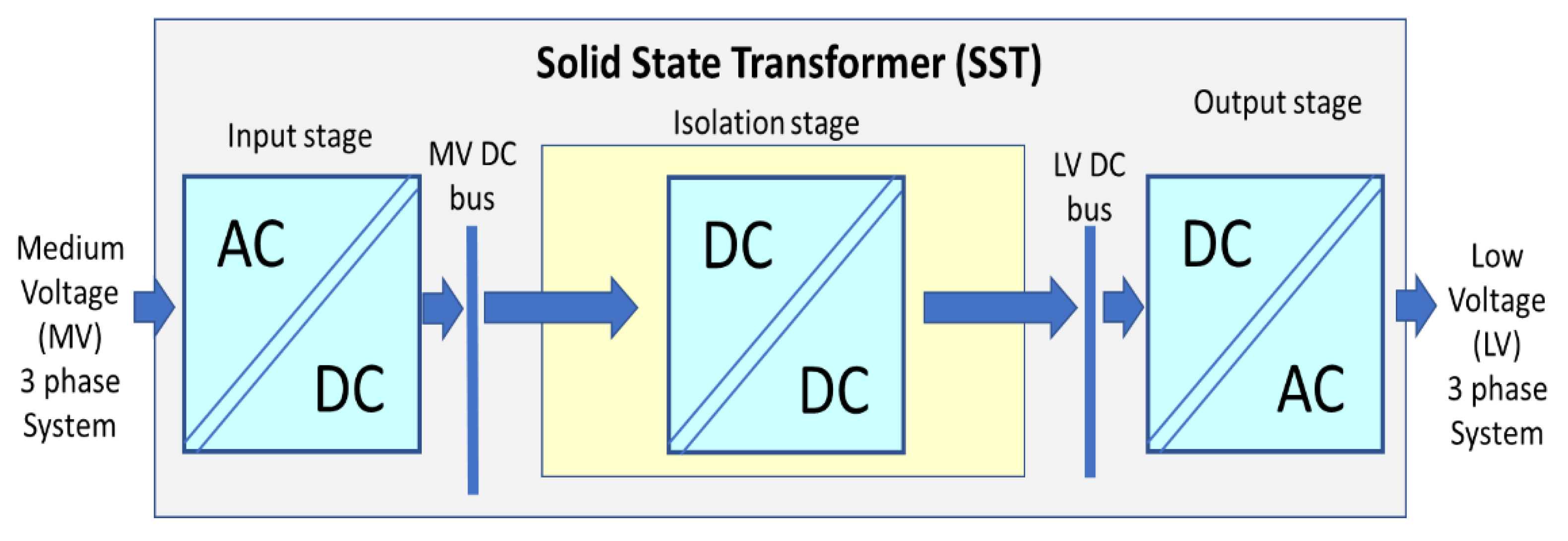
  19. She, X.; Burgos, R.; Wang, G.; Wang, F.; Huang, A.Q. Review of solid state transformer in the distribution system: From components to field application. In Proceedings of the 2012 IEEE Energy Conversion Congress and Exposition (ECCE), Raleigh, NC, USA, 15–20 September 2012; pp. 4077–4084. [Google Scholar]
  20. Eremia, M.; Liu, C.-C.; Edris, A.-Y. (Eds.) Advanced Solutions in Power Systems: HVDC, FACTS, and Artificial Intelligence; Power Engineering Series; Wiley & IEEE Press: New York, NY, USA, 2016. [Google Scholar]
  21. Hammons, T.J.; Lescale, V.F.; Uecker, K.; Haeusler, M.; Retzmann, D.; Staschus, K.; Lepy, S. State of the Art in Ultrahigh-Voltage Transmission. Proc. IEEE 2012, 100, 360–390. [Google Scholar] [CrossRef]
  22. Spagnuolo, G.; Petrone, G.; Araujo, S.V.; Cecati, C.; Friis-Madsen, E.; Gubia, E.; Hissel, D.; Jasinski, M.; Knapp, W.; Liserre, M.; et al. Renewable Energy Operation and Conversion Schemes: A Summary of Discussions During the Seminar on Renewable Energy Systems. IEEE Ind. Electron. Mag. 2010, 4, 38–51. [Google Scholar] [CrossRef] [Green Version]
  23. Kolar, J.W.; Huber, J.E. Solid-State Transformers—Key Design Challenges, Applicability, and Future Concepts. In Conference Guide; IEEE: New York, NY, USA, 2016; p. 26. [Google Scholar]
  24. Abu-Siada, A.; Budiri, J.; Abdou, A.F. Solid State Transformers Topologies, Controllers, and Applications: State-of-the-Art Literature Review. Electronics 2018, 7, 298. [Google Scholar] [CrossRef]
  25. Intelligent COMPONENTs for the Power Grid of the Future. Available online: https://phys.org/news/2018-04-intelligent-components-power-grid-future.html (accessed on 20 October 2018).
  26. Smart Transformer for the Energy Turnaround. Available online: https://techxplore.com/news/2018-09-smart-energy-turnaround.html (accessed on 20 October 2018).
  27. New Electric Car Charger Is More Efficient, 10 Times Smaller Than Current Tech. Available online: https://techxplore.com/news/2018-10-electric-car-charger-efficient-smaller.html (accessed on 21 October 2018).
  28. Zacharia, L.; Hadjidemetriou, L.; Kyriakides, E. Integration of Renewables into the Wide Area Control Scheme for Damping Power Oscillations. IEEE Trans. Power Syst. 2018, 33, 5778–5786. [Google Scholar] [CrossRef]
  29. Berckmans, G.; Messagie, M.; Smekens, J.; Omar, N.; Vanhaverbeke, L.; Van Mierlo, J.; Berckmans, G.; Messagie, M.; Smekens, J.; Omar, N.; et al. Cost Projection of State of the Art Lithium-Ion Batteries for Electric Vehicles Up to 2030. Energies 2017, 10, 1314. [Google Scholar] [CrossRef]
  30. Ayre, J. Tesla Completes World’s Largest Li-ion battery (129 MWh) in South Australia. 2017. Available online: https://cleantechnica.com/2017/11/23/tesla-completes-worlds-largest-li-ion-battery-129-mwh-energy-storage-facility-south-australia-notfree/ (accessed on 16 November 2018).
  31. Colthorpe, A. Big Solar-Plus-Storage Project Will be One of Hawaii Utility’s Lowest-Cost Power Sources. 2018. Available online: https://www.pv-tech.org/news/big-solar-plus-storage-project-will-be-one-of-hawaii-utilitys-lowest-c/ (accessed on 16 November 2018).
  32. ENTSO-E. Network Code on Requirements for Grid Connection Applicable to all Generators; ENTSO-E: Brussels, Belgium, 2016. [Google Scholar]
  33. Zacharia, L.; Kyriakou, A.; Hadjidemetriou, L.; Kyriakides, E.; Azzopardi, C.P.B.; Martensen, N.; Borg, N. Islanding and Resynchronization Procedure of a University Campus Microgrid. In Proceedings of the 2018 International Conference on Smart Energy Systems and Technologies (SEST), Sevilla, Spain, 10–12 September 2018; pp. 1–6. [Google Scholar]
  34. Huber, J.E.; Kolar, J.W. Solid-State Transformers: On the Origins and Evolution of Key Concepts. IEEE Ind. Electron. Mag. 2016, 10, 19–28. [Google Scholar] [CrossRef]
  35. Roasto, I.; Romero-Cadaval, E.; Martins, J.; Smolenski, R. State of the art of active power electronic transformers for smart grids. In Proceedings of the IECON 2012—38th Annual Conference on IEEE Industrial Electronics Society, Montreal, QC, Canada, 25–28 October 2012; pp. 5241–5246. [Google Scholar]
  36. Huang, A.Q.; Crow, M.L.; Heydt, G.T.; Zheng, J.P.; Dale, S.J. The Future Renewable Electric Energy Delivery and Management (FREEDM) System: The Energy Internet. Proc. IEEE 2011, 99, 133–148. [Google Scholar] [CrossRef]
  37. Rodriguez, J.R.; Dixon, J.W.; Espinoza, J.R.; Pontt, J.; Lezana, P. PWM regenerative rectifiers: State of the art. IEEE Trans. Ind. Electron. 2005, 52, 5–22. [Google Scholar] [CrossRef]
  38. Fernão Pires, V.; Romero-Cadaval, E.; Vinnikov, D.; Roasto, I.; Martins, J.F. Power converter interfaces for electrochemical energy storage systems—A review. Energy Convers. Manag. 2014, 86, 453–475. [Google Scholar] [CrossRef]
  39. SolarWorld Sunmodule Plus SW 300 mono. Available online: https://www.solarworld.de/en/home/ (accessed on 12 November 2018).
Figure 1. Solid state transformer design example.
Energies 11 03377 g001
Figure 2. Solid State Transformers (SST) enabling DC grids (medium and low voltage).
Energies 11 03377 g002
Figure 3. SST with a flexible connection through storage included by design. Example for unidirectional power flow.
Energies 11 03377 g003
Figure 4. Control systems for (a) inverter of the smart-transformer; (b) inverter of the PV system; (c) DC/DC converter of the storage system.
Energies 11 03377 g004aEnergies 11 03377 g004b
Figure 5. The basic configuration of the proposed SST.
Energies 11 03377 g005
Figure 6. The simulated sequence of events.
Energies 11 03377 g006
Figure 7. The one-line diagram of the SST interfaced microgrid.
Energies 11 03377 g007
Figure 8. Simulations results in Scenario 1. (a) DC bus voltage in the SST; (b) Current injected from the main grid in the DC bus of the SST; (c) The output currents of the SST (ISST), injected into the microgrid; (d) Active power evolution in different parts of the AC microgrid.
Energies 11 03377 g008aEnergies 11 03377 g008b
Figure 9. Simulation results in Scenario 2. (a) DC bus voltage in the SST; (b) Current injected from the main grid in the DC bus of the SST; (c) Output currents of the SST (ISST), towards the microgrid (real-time values); (d) Active power evolution in different parts of the AC microgrid.
Energies 11 03377 g009aEnergies 11 03377 g009b
Figure 10. Superposition of the SST DC bus voltage variation in both scenarios (1 and 2).
Energies 11 03377 g010

