Hot-Swappable Modular Converter System Control for Heterogeneous Batteries and ESS

1
Korea Electronics Technology Institute 226, Cheomdangwagi-ro, Buk-gu, Gwangju 61011, Korea
2
Department of Electrical Engineering, Chonnam National University, Gwangju 61186, Korea
*
Author to whom correspondence should be addressed.
Energies 2018, 11(2), 309; https://doi.org/10.3390/en11020309
Submission received: 26 December 2017
/
Revised: 29 January 2018
/
Accepted: 30 January 2018
/
Published: 1 February 2018
(This article belongs to the Section D: Energy Storage and Application)
Abstract
:This study proposes a modular bidirectional converter system for hot-swappable energy storage systems (ESSs). The proposed modular converter has a four-leg interleaved structure, and therefore it can reduce input current ripples and is suitable for secondary cells. Moreover, if any of the legs fails, hot-swap is available through phase control inside the converter. The modular converter uses an independently controllable battery as an input power source, allowing the charge and discharge control according to each stated of charge (SOC). The output voltage of the converter circumvents the module in the event of a high-voltage output control and a fault (exchange due to battery life, repair of converter) through the cascade-type bypass, thereby enabling continuous operation. The hot-swap operation of the proposed modular ESS converter system and the charge and discharge control algorithm according to battery SOC are verified by experiment.
1. Introduction
The ever-growing power consumption and the demand for high-quality power are bringing distribution power systems into increasing prominence. The current centralized power systems entail several disadvantages including low power conversion efficiency, low power density, and poor performance in voltage control arising from the losses on transmission lines as the distance widens between converters and loads. The application of distributed power systems comes in this context with the aim of addressing these issues [1,2,3]. This trend is also accompanied by the growing use of modular multilevel converters (MMCs) in order to satisfy the demand for high-quality electricity. High-power MMCs have the capacity of a several kilowatts feature-enhanced system, as well as reliability, with lower electrical and thermal fatigue compared to single modular converters and a reduced volume and size of radiator panels due to the distribution of heat sources in switching devices. MMCs can also increase the switching frequency compared to single modular converters through interleaved control, thereby decreasing the filter size and input current ripples [4,5,6]. Driven by their high system stability and low input current ripples, MMCs are widely implemented in battery-powered energy storage systems (ESSs) as well as for charging and discharging converters in electric vehicles [7,8,9].
Recent trends in control technology for modular converter-based ESS include satisfying diverse consumer needs and cutting maintenance and replacement costs [10,11,12]. To ensure the continued normal operation of ESS while enabling the repair and replacement of their components requires the establishment of a hot-swap system, along with technologies for its operation [13,14].
In light of these considerations, this study proposes a modular ESS converter system capable of hot-swap. The proposed converter comprises a four-leg interleaved converter topology, reducing the input current ripples and making each leg hot-swappable. Further, the cascade-type module bypass function, another feature of the proposed device, enables hot-swap in the event of a converter fault (replacing the battery, repair of converter components). Furthermore, independently controllable batteries for each module enable the application of various types of batteries, which, in turn, facilitates the enlargement of the ESS capacity. The above-mentioned modular converter topology is configured for a DC output and thus allows for easy high-voltage configuration for DC links in the inverter. This topology also regulates the output voltage for balanced or unbalanced power control depending on the state of charge (SOC) of the batteries. This study establishes the feasibility of a hot-swappable modular converter topology through experiments.
2. Structure of the Proposed System
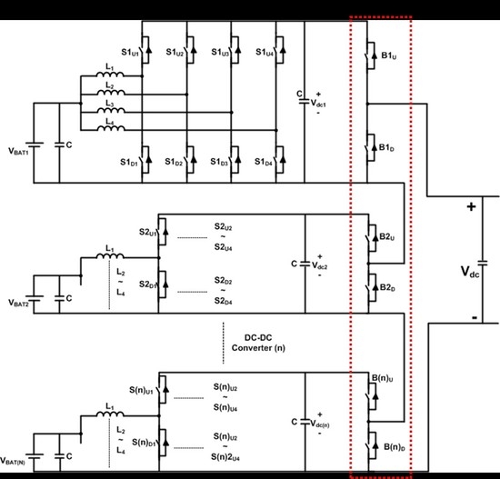
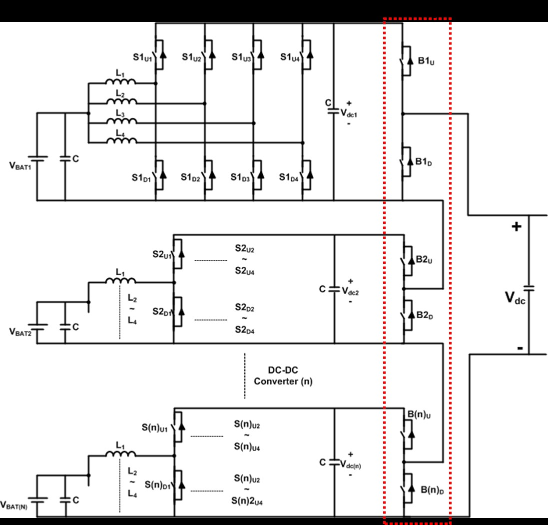
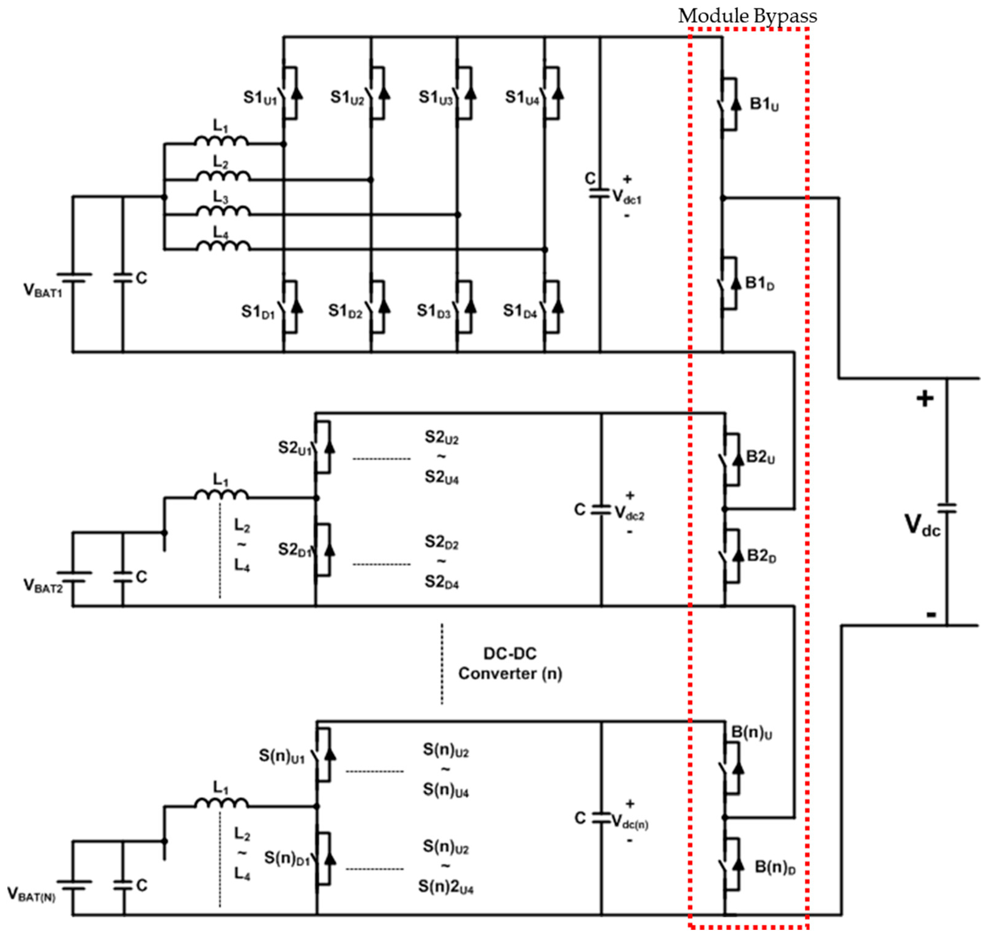
This study proposes a hot-swap topology to build a modular converter-based ESS, enable the application of heterogeneous battery types, and reduce the time required for maintenance and replacement with the aim of enhancing system reliability and performance. The proposed bidirectional converter system for ESSs is a multi-input modular converter (MIMC) and is illustrated in Figure 1. To design a modular converter, a four-leg topology was designed for each single converter and a bypass topology was added to make the converter hot-swappable so as to facilitate maintenance and replacement [15,16,17]. The dotted line illustrates the module bypass topology.
2.1. Four-Leg Interleaved Bidirectional Converter
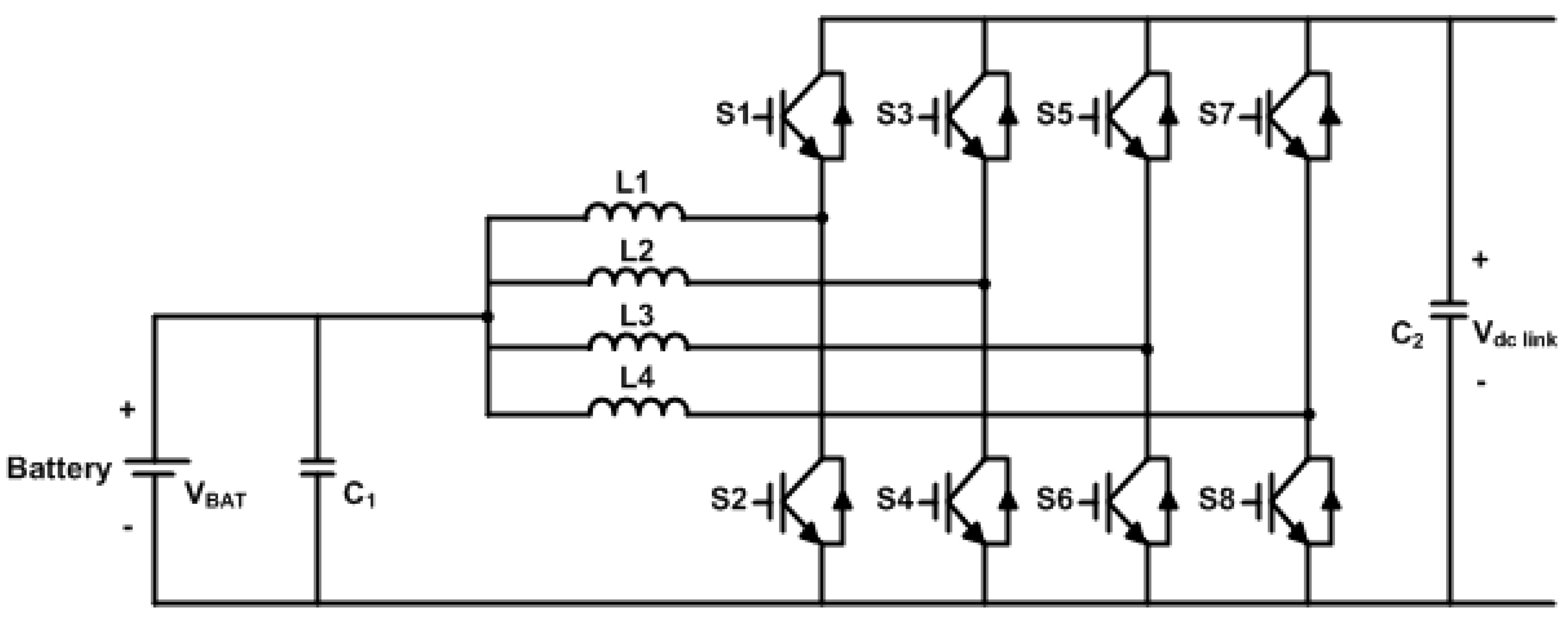
The four-leg bidirectional converter consists of four half-bridge converters connected in parallel, where eight switches trigger the device into a charge or discharge mode by controlling the current and voltage. The four-leg interleaved converter alternates between the on and off modes with a phase difference of 90° (2π/N (where N is the number of legs)). The inductor current, overlapped by the phase difference, can acquire current continuity; this increases the battery lifespan and reduces the volume and size of manual elements. Figure 2 illustrates the topology of the proposed four-leg bidirectional interleaved converter. In the Figure 2, VBAT is the voltage of battery, C1 and C2 is capacitor and L1, L2, L3 and L4 is the reactors. S1, S2, S3, S4, S5, S6, S7 and S8 is insulated gate bipolar transistor (IGBT).
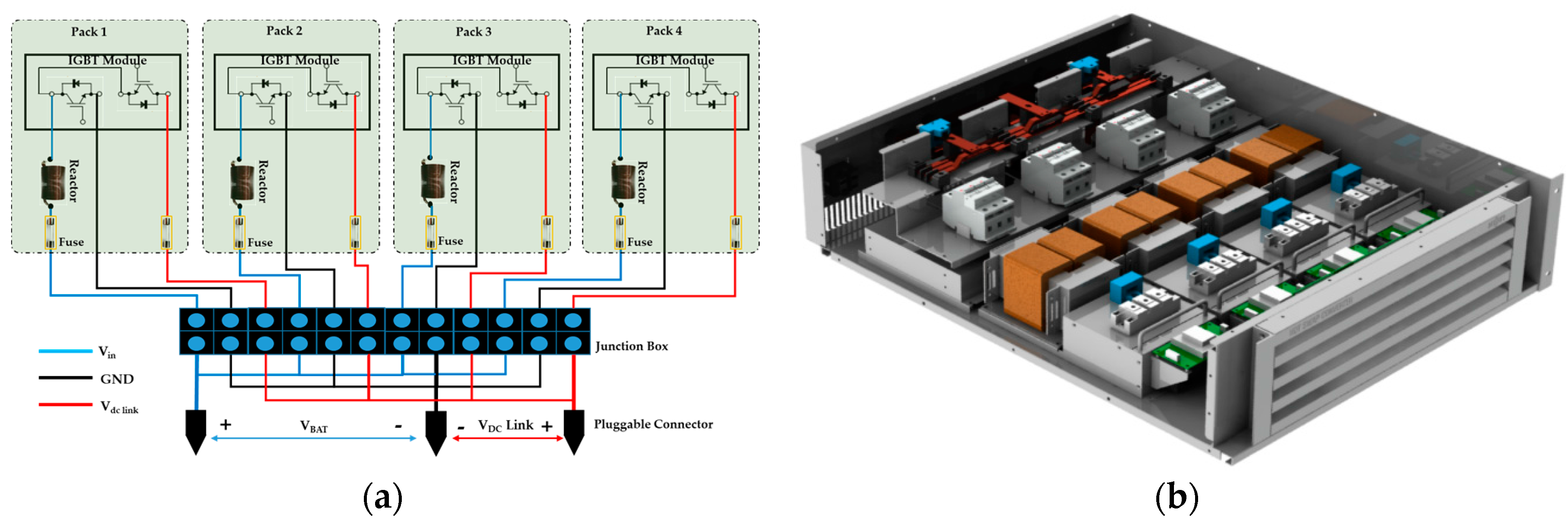
In case of a leg fault due to an overcurrent or a deteriorated switching device, the converter inside the module has a hot-swap hardware structure, illustrated in Figure 3, which allows the replacement of the power converter in the live condition. The failure of power semiconductors in power converters mostly involve short-circuit conditions, in which case a power fuse switches all faulty parts to an open-circuit mode. Each leg in the converter is thus a pack that contains an Insulated gate bipolar transistor (IGBT) module, an inductor, and a power fuse. The voltage of the input/output terminal is connected through a junction box depending on the number of packs. A faulty pack can be replaced in the live condition.
2.2. Module Bypass Configuration
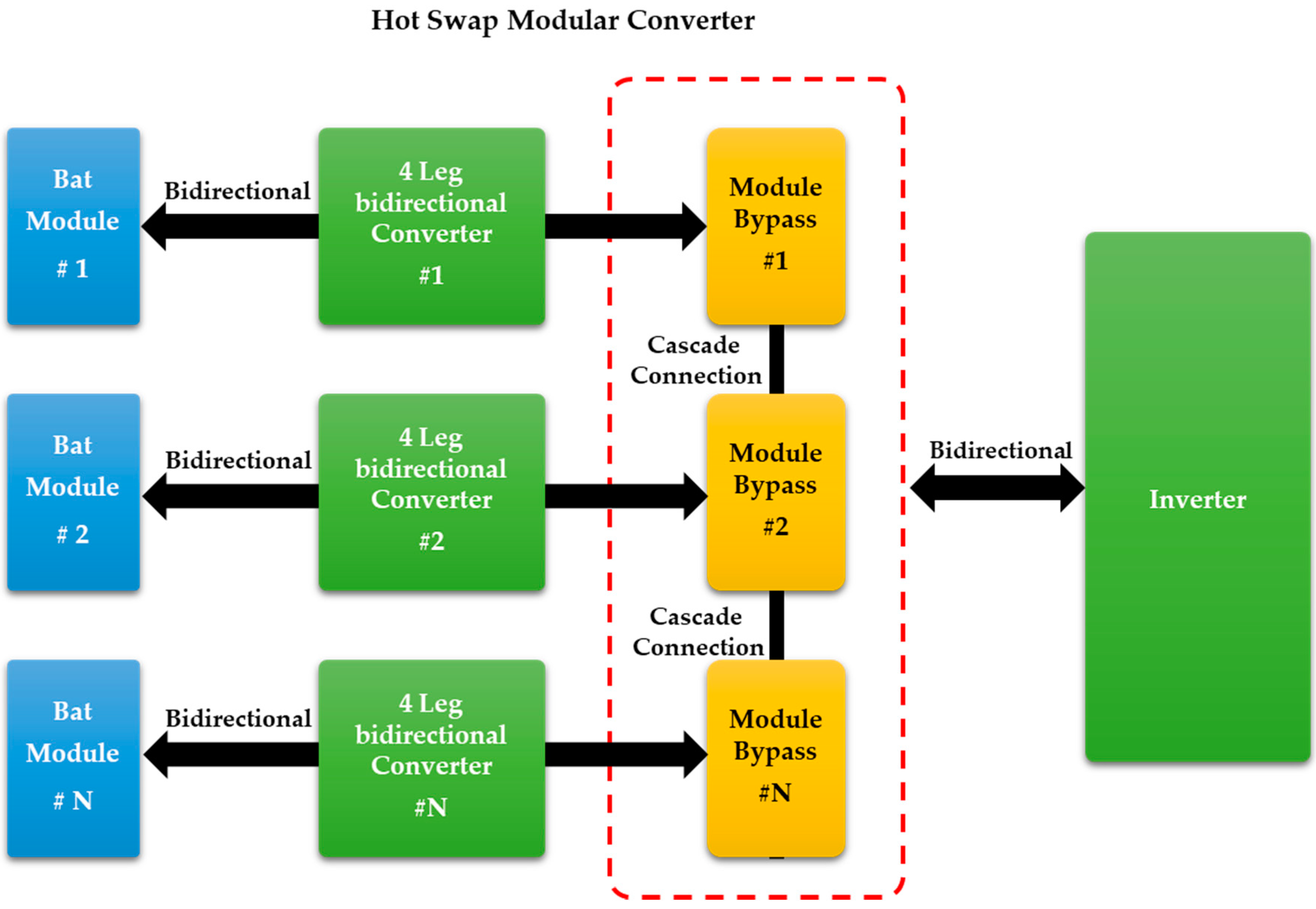
Figure 4 illustrates the MIMC proposed in this study. This modular-based converter allows independent control of the batteries for each module, thus allowing the application of batteries of different types and facilitating the expansion of battery capacity. The module bypass configured in series allows faulty modules to be bypassed through switch operations, enabling hot-swap operation.
3. Control Strategy for Hot-Swap
3.1. Controller Design
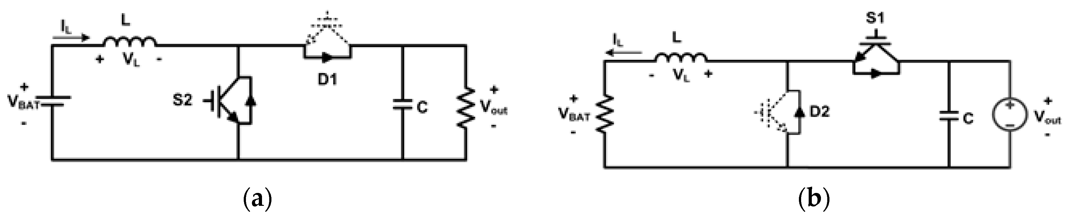
Figure 5 illustrates the equivalent circuit for one phase of a four-leg bidirectional converter.
Figure 5a shows the circuit in the discharge mode, where the device operates in a boost mode to convert low battery voltage into high voltage for the DC link. The average voltage VL(AVG) across both terminals of the inductor L in the boost mode is given by
Figure 5b illustrates the circuit in the charge mode, where the device operates in a buck mode to send the high-voltage DC link power into the batteries with relatively lower input voltage. The average voltage VL(AVG) across both terminals of the inductor L in the buck mode
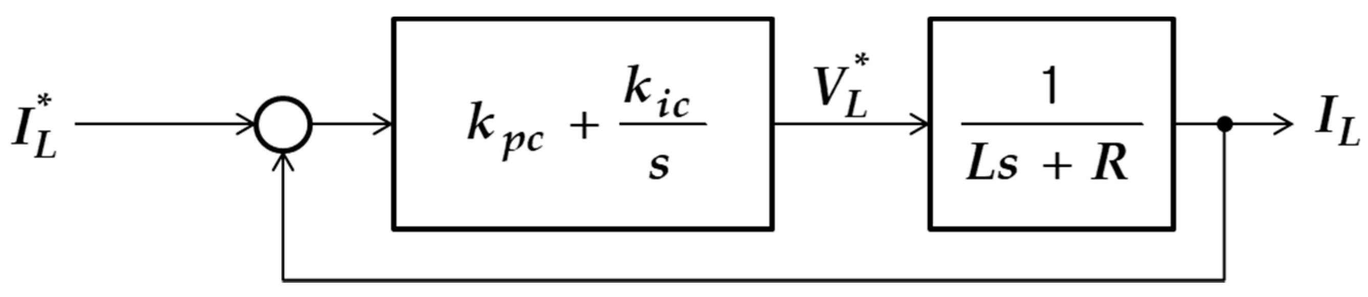
where TS denotes the switching interval, ton denotes the on time of the switching devices, and D denotes the pulse width modulation (PWM) duty ratio. A current controller is configured with a proportional-integral controller and the output of the controller is assumed as the voltage command for the inductor L (VL*). Then, the block diagram for current control will appear as shown in Figure 6.
Assuming that the average voltage applied to the inductor (VL(AVG)) and the voltage command (VL*) are the same, D is represented as follows depending on the charge and discharge modes:
Assuming that the current control takes place smoothly as per the current command on the inductor, this can lead to the same effect as a direct control on the average current of the capacitor. The equation below describes the relationship between the average current of the inductor, denoted by IL, and that of the capacitor, denoted by Ic:
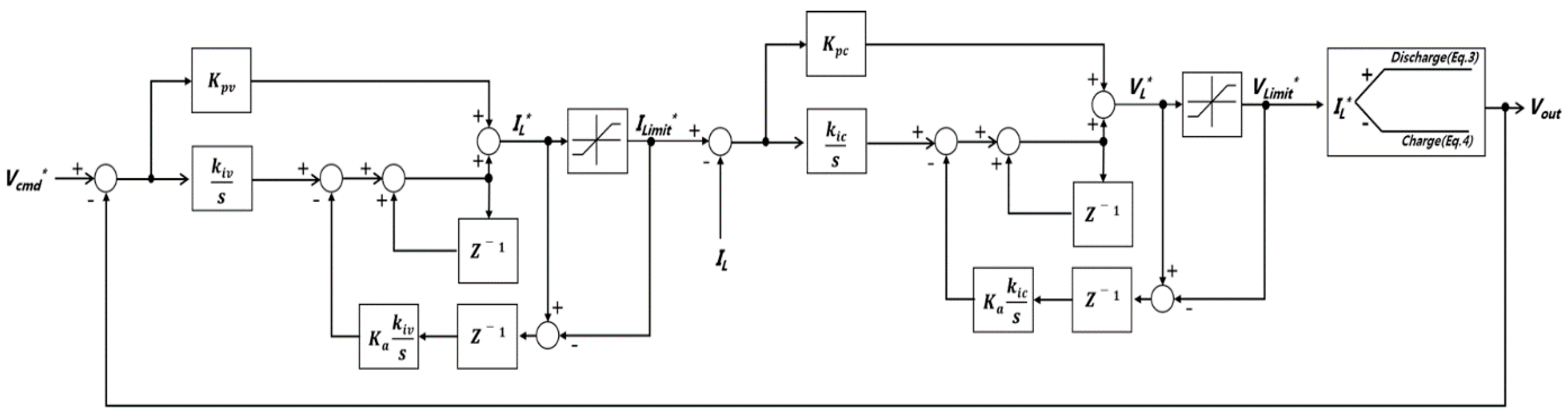
If the voltage controller generates the capacitor current command, and the current control is performed with the control command for the inductor current obtained from Equation (5), the configuration of the capacitor voltage controller will appear as shown in Figure 7.
For voltage control of the four-leg interleaved converter, the capacitor current command (IC*) is generated by the error between the commanded and output voltages and the PI control. This command is then converted into the current command (IL*) using the capacitor average current model (IL*). The charge or discharge mode of the current controller is determined according to the value of the current command, and the PWM duty ratio of the switch is calculated through the average inductor voltage command (VL*). The current limit represents the allowable current value for charging or discharging the battery. Figure 8 shows the block diagram for voltage control of the four-leg interleaved converter.
3.2. Four-Leg Converter for Hot-Swap
The four-leg interleaved converter, in the absence of a faulty leg, controls the phase delay angle with a 90° angle difference between each phase. When hot-swap occurs inside the converter due to faulty legs, the phase delay angle increases to 120° in case of one faulty leg and 180° in case of two faulty legs. The phase difference in the presence of faulty legs can be calculated using
and the switching pattern in this case is shown in Figure 9.
3.3. MIMC for Hot-Swap
An MIMC equipped with various types of batteries performs balanced and unbalanced power control depending on the SOC of the batteries. If each battery is in a very similar SOC, to ensure power balance between the modular converters, the MIMC controls the converter voltage commands in a way that they have the same value. Further, in the case of a wide gap in the SOC between batteries, the MIMC applies voltage commands of differing values for each converter to perform unbalanced control and thereby maintain the SOC at a similar level between batteries. This contributes to enhanced system reliability.
The cascade-type modular converter, designed to implement hot-swap in the MIMC, must maintain high voltage for the DC link to keep the inverter in operation even in the event of module bypass. To this end, the value of the voltage command is determined using
depending on the state of each single converter during hot swap.
The four-leg interleaved converter, depending on its state, controls the T1 and T2 bypass switches for each module, which allows the device to redirect the electrical flow to bypass faulty modules. Figure 10 illustrates the operation of hot-swap switches in the event of faulty modules.
The module bypass control algorithm for hot-swap is as shown in Figure 11. In case of the converter module fails, turn on the module switch (BxD) to bypass the failed module and other normal operation converter module will share the load with the same voltage control.
4. Experimental Results
Figure 12 shows the test setup for implementing the hot-swap function of the proposed modular converter. The test setup consisted of a bidirectional DC power supply system, three 10-kWh lead-acid batteries, three 6-kW modular converters, a bypass module, measuring instruments (oscilloscope, power analyzer), and a loader. The passive elements and, test specifications of the modular converter are shown in Table 1.
4.1. Result of Hot-Swap Experiment for Four-Leg Single Modular Converter
Figure 13 shows the response waveforms at charge/discharge modes of the single modular converter using the proposed four-leg converter topology. Figure 13a is the charge waveform, and Figure 13b is the discharge waveform. The converter using the interleaving technique of 90° phase shift shows a good division of 1/4 times current for each leg at charge/discharge and reduces input current ripples. Figure 14 shows that the efficiency of the single modular converter is over 98%.
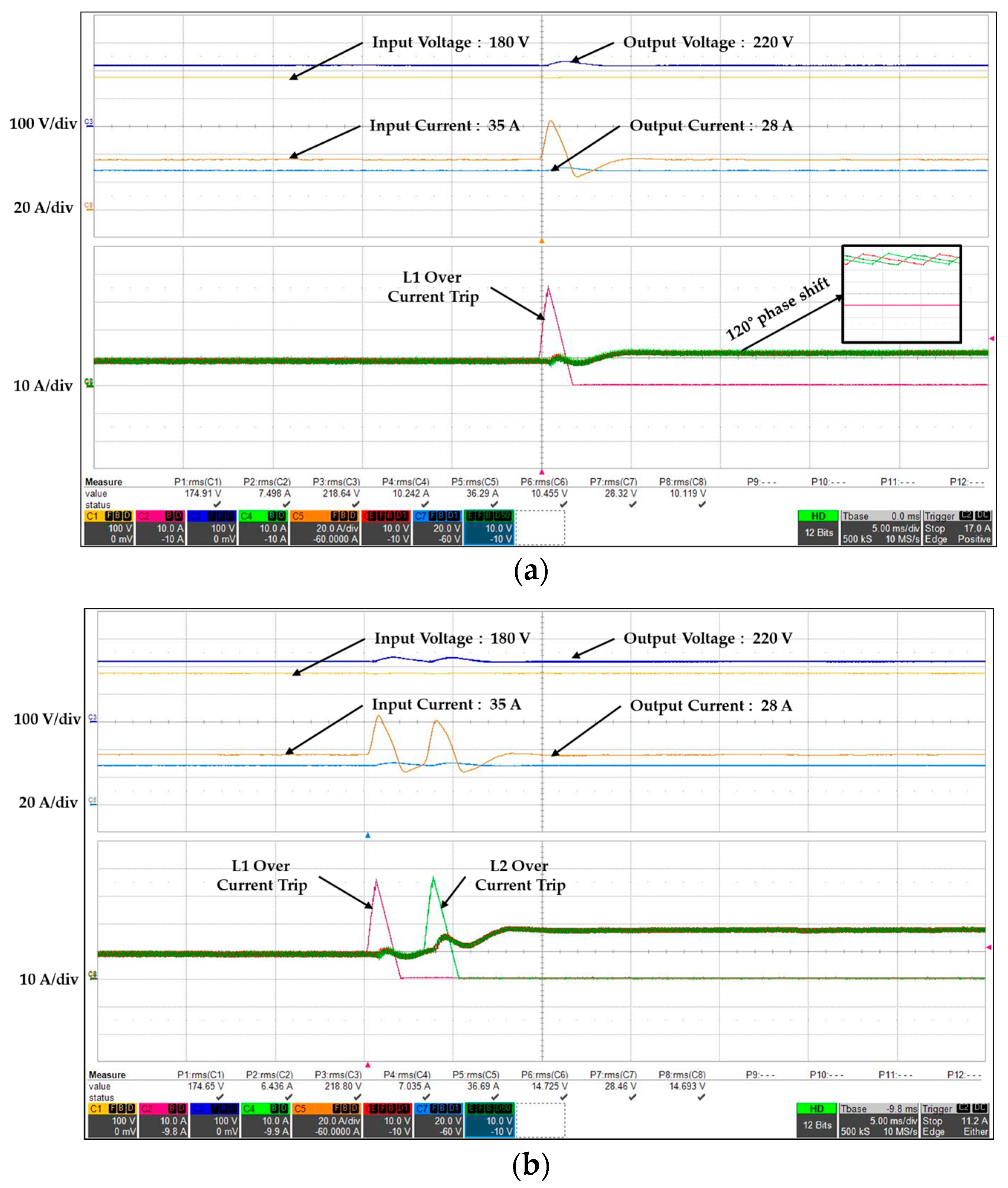
Figure 15 illustrates the test results for the hot-swap function of the single modular converter. The hot-swap function is to ensure a good output state in the event of one or two faulty legs out of the four legs. This function is confirmed by the response waveform for the leg fault in the charge mode. Figure 15a is the response waveform for the fault of leg 1. The open state is maintained after over current, and the current was well divided among the remaining legs with a 120° phase shift, which indicates the normal operation of the converter. Figure 15b shows the response waveform for the consecutive faults of legs 1 and 2. In the case of two faulty legs, the current was well divided among the remaining legs with a 180° phase shift, which also indicates the stable operation of the converter.
Figure 16 illustrates the response waveforms in the hot-swap test for the single modular converter in the discharge mode. The same test conditions for the charge mode were applied. In the case of leg fault in the discharge mode, the phase shift interleaved switching control was well operated.
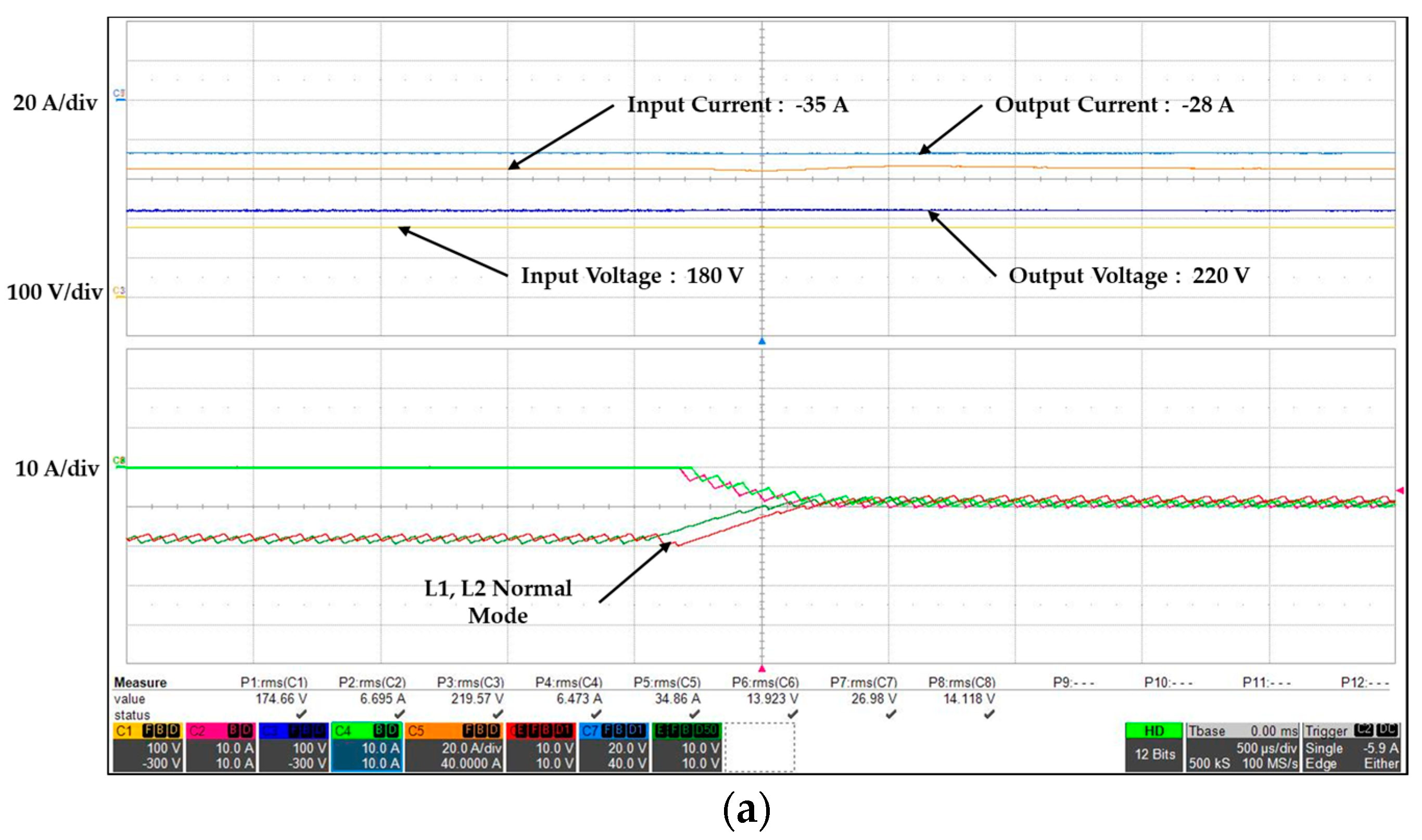
Figure 17 shows the response waveforms of the hot-swap function for the return to normal mode. In other words, the figure illustrates current and voltage at the normal mode of legs. Figure 17a,b illustrate the charge and discharge modes, respectively. After the recovery of fault, the current distribution on each inductor and the operation of the converter showed good performance.
4.2. Results of Hot-Swap Experiment for the Modular Converter System
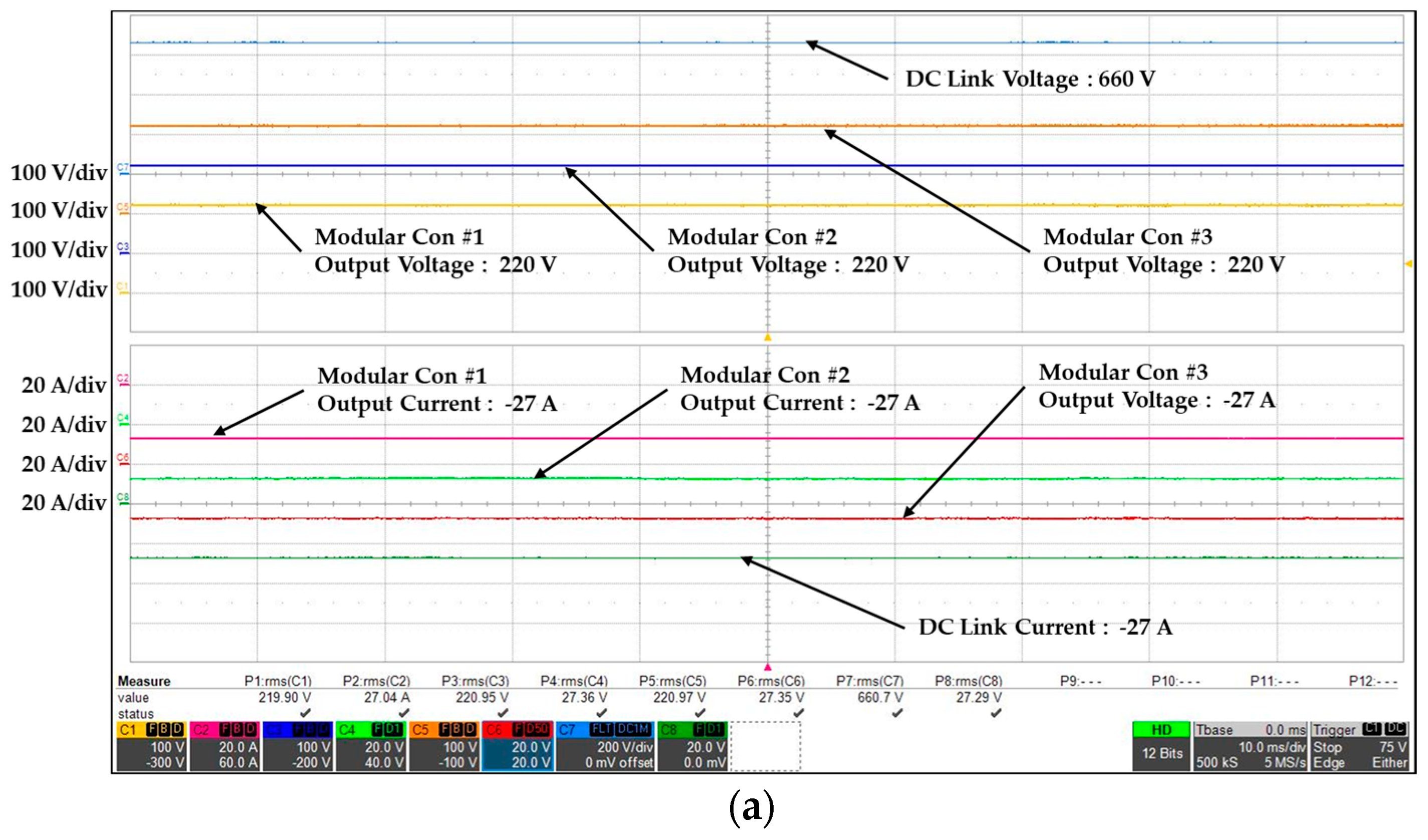
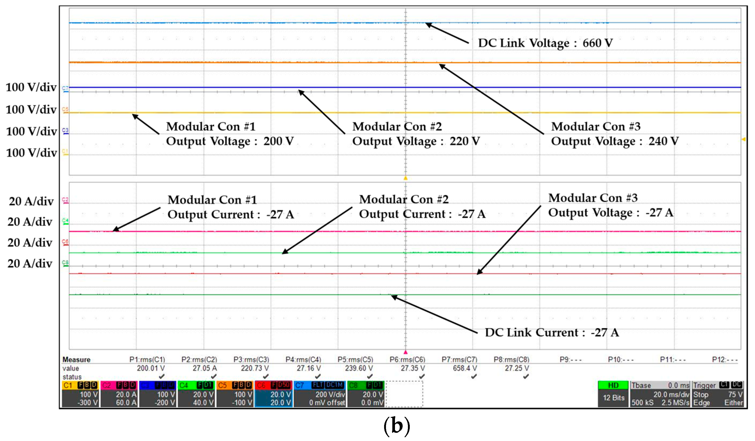
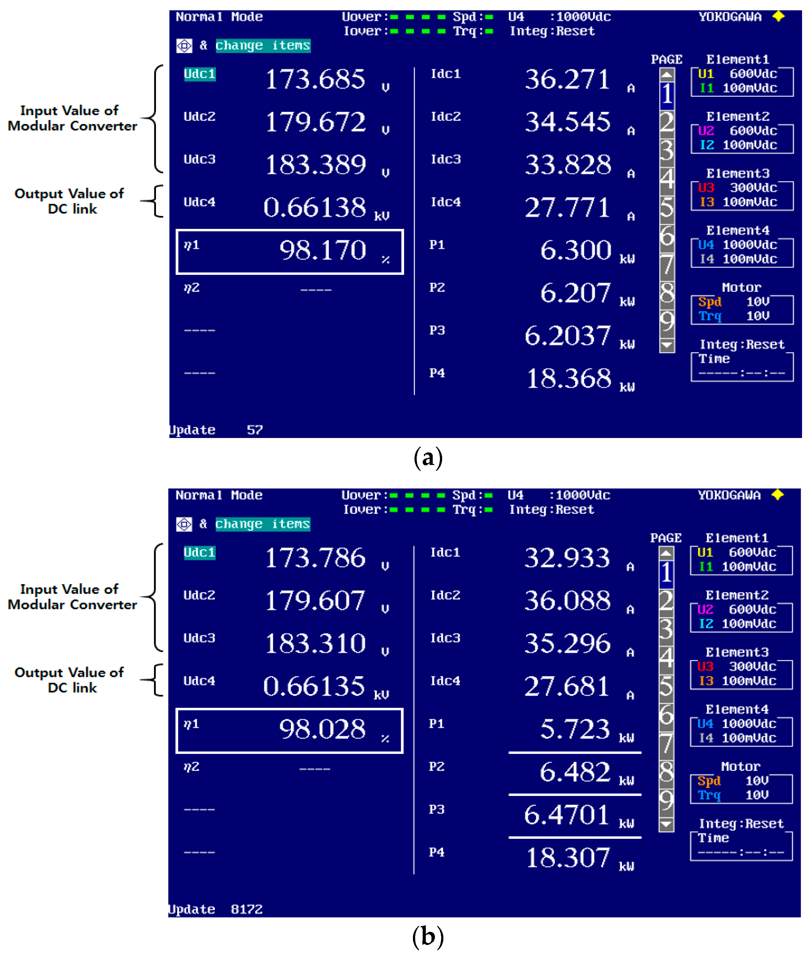
The experimental results for the modular converter system, where three four-leg converters were connected in series, are as follows. The modular converter system was set to control DC link voltage at 660 V in order to drive the grid-connected inverter. Figure 18 shows the charge test results of the modular converter system according to battery SOC values. Figure 18a presents the response waveforms under the condition that each battery has the same SOC, while Figure 18b displays the response waveforms under the condition that Battery 1 has the highest SOC, followed by Battery 2 and Battery 3. In the charge mode, the output can be increased by increasing the converter voltage of the battery with low SOC. It turns out that the current in DC link flows is evenly distributed to each converter and the voltage control is well maintained even when each battery has a different SOC value.
Figure 19 presents the output values of the modular converter system in the charge mode according to the battery SOC value. When the SOC was equal, each converter had the same output power. On the other hand, when the SOC was different, the output power was the highest for the battery with the lowest SOC.
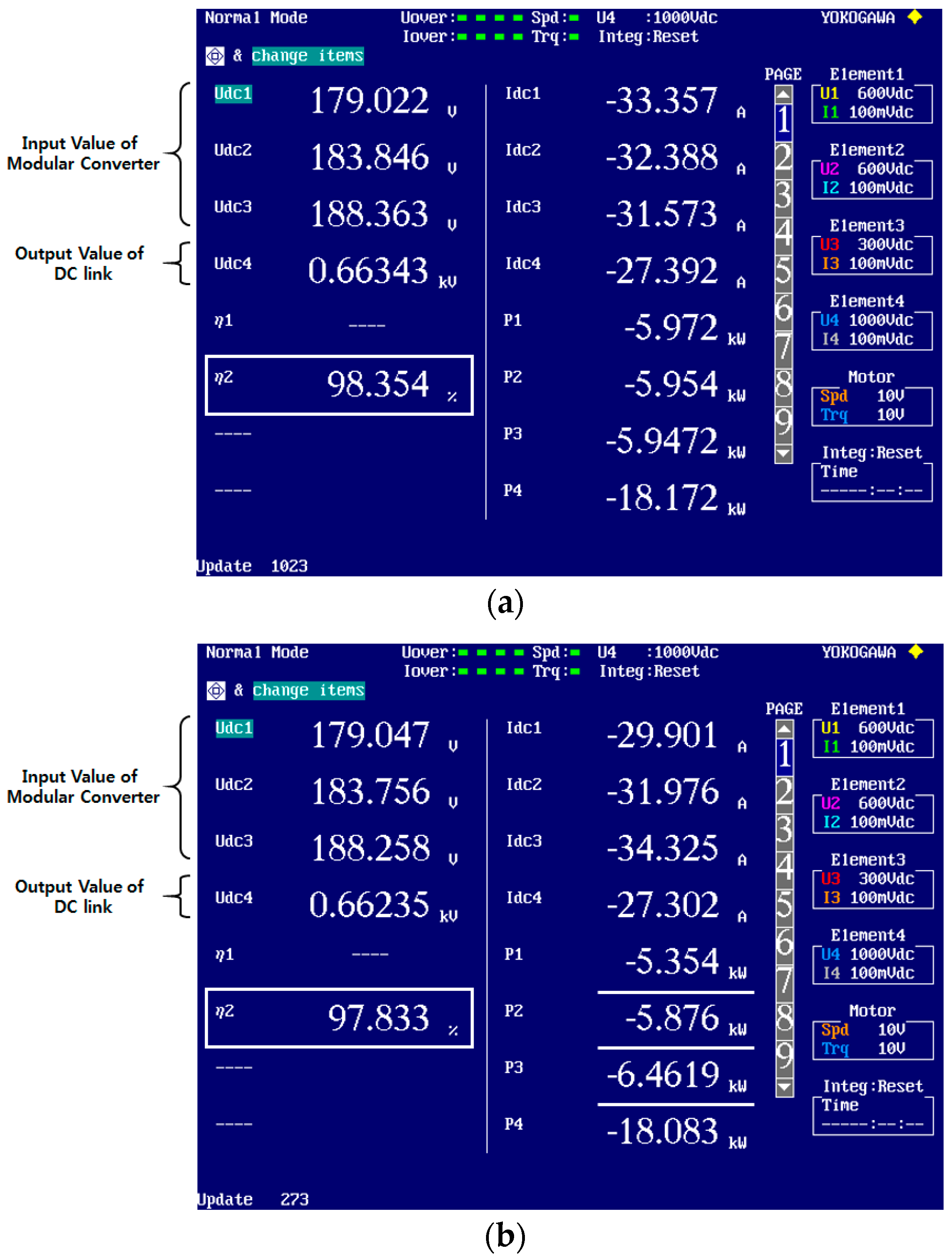
Figure 20 shows the discharge test results of the modular converter system according to the battery SOC value. Figure 20a assumes that each battery has the same SOC, while Figure 20b applies the condition that batteries 2 and 3 have the highest SOC and battery 1 has the lowest SOC. In opposition to the charge mode, when the modular converter system is in the discharge mode, the output can be decreased by reducing the converter voltage of the battery with the low SOC. The voltage control and operation of each converter showed good performance in the discharge mode.
Figure 21 presents the output values of the modular converter system in the discharge mode according to the battery SOC. When the SOC is equal, the output power of each converter is the same. On the other hand, when the SOC is different, the output power of the battery with the lowest SOC is the lowest.
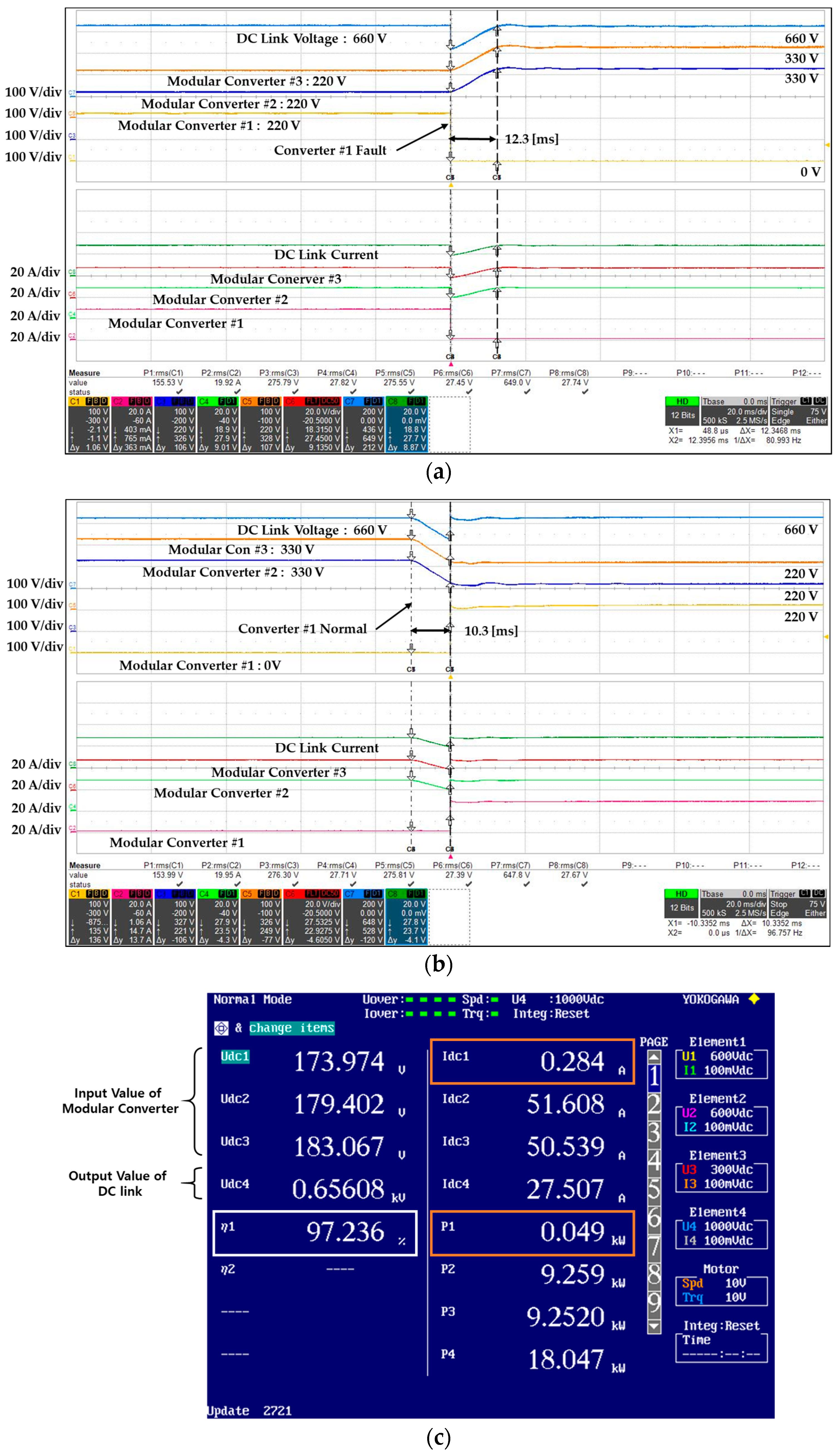
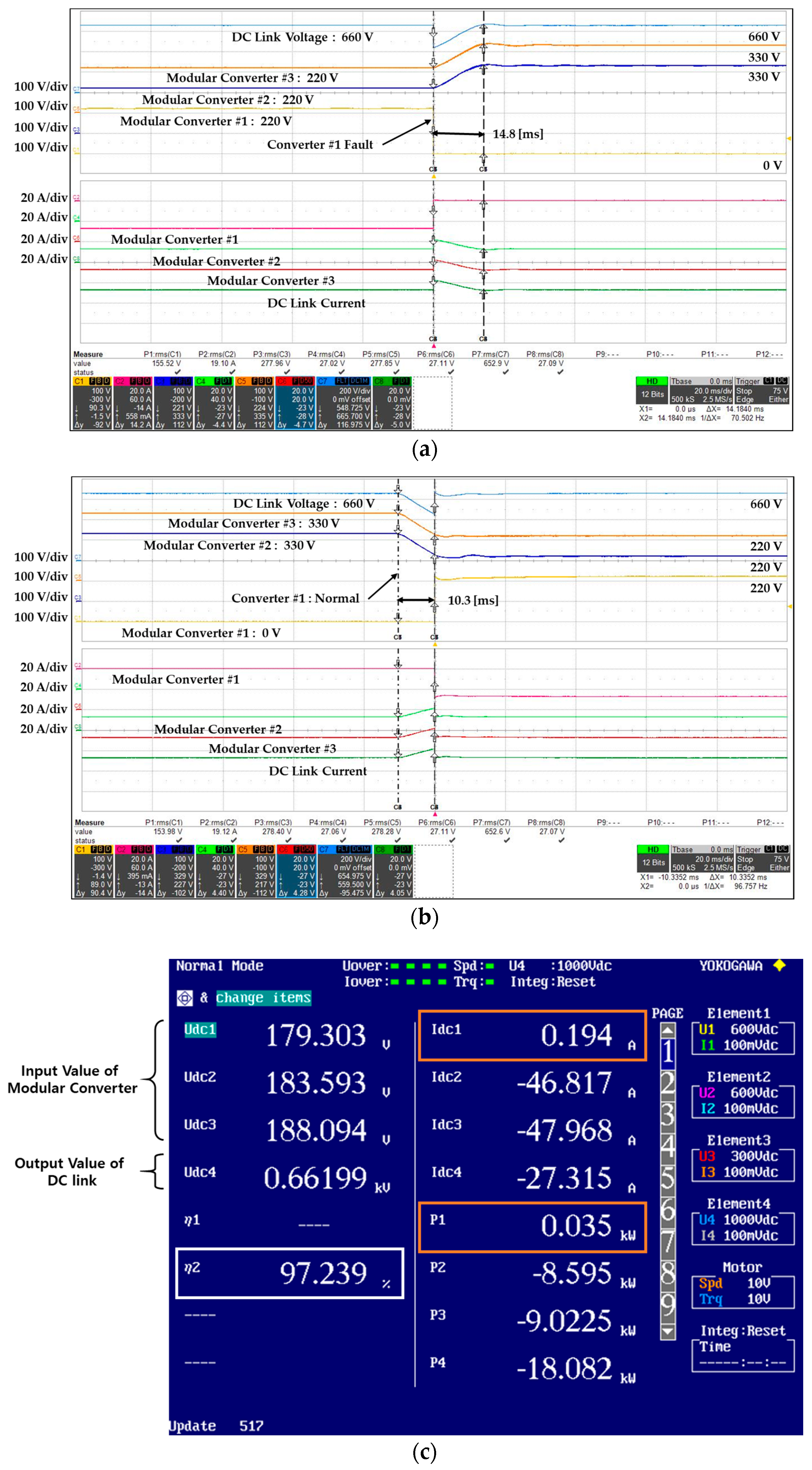
Figure 22 provides the experimental results for the hot-swap function of the modular converter system. The results are presented as the response waveforms in the battery charge mode. In Figure 22a, the bypass switch (B1D_ON) was driven owing to the fault of modular converter #1. In Figure 22b, modular converter 1 returns to the normal mode (B1U_ON). When one modular converter is faulty, the other converter increases the instantaneous voltage boost ratio to generate the DC link voltage. When the converter returns to the normal mode, the voltage boost ratio of the other converter is controlled to be low in order to prevent the rise of the DC link voltage. Consequently, while the modular converter system is charged, whether one converter is faulty or returns to normal mode, the other converter shows good performance in terms of automatic voltage control. In addition, the modular converter system maintains normal operation during hot-swap, and the transient time is within one cycle (16.67 ms) of the inverter. Figure 22c shows that the efficiency of the modular converter for hot-swap is over 97%.
Figure 23 presents the response waveforms of the hot-swap test during battery discharge. The test conditions were the same as those of the charge test. The hot-swap function is good enough during the discharge of the modular converter system, whether one converter is faulty or returns to the normal mode.
5. Conclusions
This study proposed a hot-swappable modular bidirectional converter MIMC for ESSs. The modular bidirectional converter has a four-leg structure, where the interleaved technique using the phase shift of each leg was applied to reduce current ripples. A high-efficiency converter system was also implemented. The hot-swap function within the converter was also implemented through the phase shift of each leg. Uniform control and differential control using independent battery power were used to conduct the charge/discharge control test for each SOC. The hot-swap function allowed the modular bidirectional converter to circumvent the high-voltage output and the converter fault through the cascade-type module bypass. When the hot-swap function of each converter was implemented, the transient time was within 16 ms (one cycle), which indicates good operation, and the normal operation was possible if the grid-connected inverter is connected. In order to analyze the performance of the proposed modular bidirectional converter, the battery and bidirectional DC power supply system were used for the experiment. Good performance was confirmed for the normal and hot-swap operations of each single converter and the normal and hot-swap operations of the modular converter system. The validity of the proposed algorithm was demonstrated.
Acknowledgments
This work was supported by the Korea Institute of Energy Technology Evaluation and Planning (KETEP) and the Ministry of Trade, Industry & Energy (MOTIE) of the Republic of Korea (No. 20162010104490).
Author Contributions
All the authors contributed equally to this work. Dae-Seak Cha conceived and wrote the manuscript, designed and performed the experiments. Jung-Sik Choi and Seung-Yeol Oh contributed to the conceptual approach and provided important comments on the modeling and analysis. Hyun-Jin Ahn and Young-Cheol Lim conceived the outline, wrote and revised the manuscript. All the authors discussed the results and implications, and commented on the manuscript at all stages.
Conflicts of Interest
The authors declare no conflict of interest.
References
- Rodriguez, J.; Lai, J.S.; Peng, F.Z. Multilevel inverters: A survey of topologies, controls, and applications. IEEE Trans. Ind. Electron. 2002, 49, 724–738. [Google Scholar] [CrossRef]
- Franquelo, L.G.; Rodriguez, J.; Leon, J.I.; Kouro, S.; Portillos, R. The age of multilevel converters arrives. IEEE Ind. Electron. Mag. 2008, 2, 28–39. [Google Scholar] [CrossRef]
- Carpita, M.; Marchesoni, M.; Pellerin, M.; Moser, D. Multilevel Converter for Traction Applications: Small-Scale Prototype Tests Results. IEEE Trans. Ind. Electron. 2008, 55, 2203–2212. [Google Scholar] [CrossRef]
- Garinto, D. Multi-interleaved zero-ripple VRM to power future microprocessors. In Proceedings of the 2007 European Conference on Power Electronics and Applications, Aalborg, Denmark, 2–5 September 2007; pp. 2–5. [Google Scholar]
- Wang, Y.-F.; Xue, L.-K.; Wang, C.-S.; Wang, P.; Li, W. Interleaved High-Conversion-Ratio Bidirectional DC–DC Converter for Distributed Energy-Storage Systems—Circuit Generation, Analysis, and Design. IEEE Trans. Power Electron. 2016, 31, 5547–5561. [Google Scholar] [CrossRef]
- Yu, W.; Qian, H.; Lai, J.-S. Design of High-Efficiency Bidirectional DC–DC Converter and High-Precision Efficiency Measurement. In Proceedings of the IECON 2008 34th Annual Conference of IEEE Industrial Electronics, Orlando, FL, USA, 10–13 November 2008; pp. 658–690. [Google Scholar]
- Lai, J.-S.; Nelson, D.J. Energy Management Power Converters in Hybrid Electric and Fuel Cell Vehicles. IEEE. Proc. 2007, 95, 766–777. [Google Scholar] [CrossRef]
- Marchesoni, M.; Vacca, C. New DC–DC converter for energy storage system interfacing in fuel cell hybrid electric vehicles. IEEE Trans. Power Electron. 2007, 22, 301–308. [Google Scholar] [CrossRef]
- Abbey, C.; Joos, G. Supercapacitor Energy Storage for Wind Energy Applications. IEEE Trans. Ind. Appl. 2007, 43, 769–776. [Google Scholar] [CrossRef]
- Thomas, S.; Stieneker, M.; De Doncker, R.W. Development of a modular high-power converter system for battery energy storage system. In Proceedings of the 2011 14th European Conference on Power electronics and Applications (EPE 2011), Portland, OR, USA, 8–10 June 2005. [Google Scholar]
- Hillers, A.; Biela, J. Optimal design of the modular multilevel converter for an energy storage system based on split batteries. In Proceedings of the 2013 15th European Conference on Power electronics and Applications (EPE), Lille, France, 2–6 September 2013. [Google Scholar]
- Kawakami, N.; Ota, S.; Kon, H.; Konno, S.; Akagi, H.; Kobayashi, H.; Okada, N. Development of a 500 kW Modular Multilevel Cascade Converter for battery energy storage systems. IEEE Trans. Ind. Appl. 2014, 50, 3902–3910. [Google Scholar] [CrossRef]
- Wu, W.; Wu, X.; Yin, J.; Jing, L.; Wang, S.; Li, J. Characteristic Analysis and Fault-Tolerant Control of Circulation Current for Modular Multilevel Converters under Sub-Module Faults. Energies 2017, 10, 1827. [Google Scholar] [CrossRef]
- Liu, H.; Ma, K.; Loh, P.C.; Blaabjerg, F. Online Fault Identification Based on an Adaptive Observer for Modular Multilevel Converters Applied to Wind Power Generation Systems. Energies 2015, 8, 7140–7160. [Google Scholar] [CrossRef]
- Zheng, Z.; Wang, K.; Xu, L.; Li, Y. A Hybrid Cascaded Multilevel Converter for Battery Energy Management Applied in Electric Vehicles. IEEE Trans. Power Electron. 2014, 29, 3537–3546. [Google Scholar] [CrossRef]
- Trintis, I.; Munk-Nie1sen, S.; Teodorescu, R. Cascaded H-bridge with bidirectional boost converters for energy storage. In Proceedings of the 2011 14th European Conference on Power Electronics and Applications (EPE 2011), Birmingham, UK, 30 August–1 September 2011. [Google Scholar]
- Akagi, H. Classification, terminology, and application of the modular multilevel cascade converter (MMCC). In Proceedings of the 2010 International Power Electronics Conference (IPEC), Sapporo, Japan, 21–24 June 2011; Volume 26, pp. 3119–3130. [Google Scholar]
Figure 1.
Diagram of the proposed hot-swap modular converter.

Figure 2.
Four-leg bidirectional converter topology.

Figure 3.
Four-leg bidirectional converter hardware configuration: (a) Structure of hot-swap model; (b) Three Dimensions (3D) model.
Figure 3.
Four-leg bidirectional converter hardware configuration: (a) Structure of hot-swap model; (b) Three Dimensions (3D) model.

Figure 4.
Hot-swap structure using bypass module.

Figure 5.
Equivalent circuit diagram for bidirectional converter: (a) Discharge mode; (b) Charge mode.
Figure 5.
Equivalent circuit diagram for bidirectional converter: (a) Discharge mode; (b) Charge mode.

Figure 6.
Block diagram for current control on the inductor.

Figure 7.
Block diagram for a capacitor voltage controller.
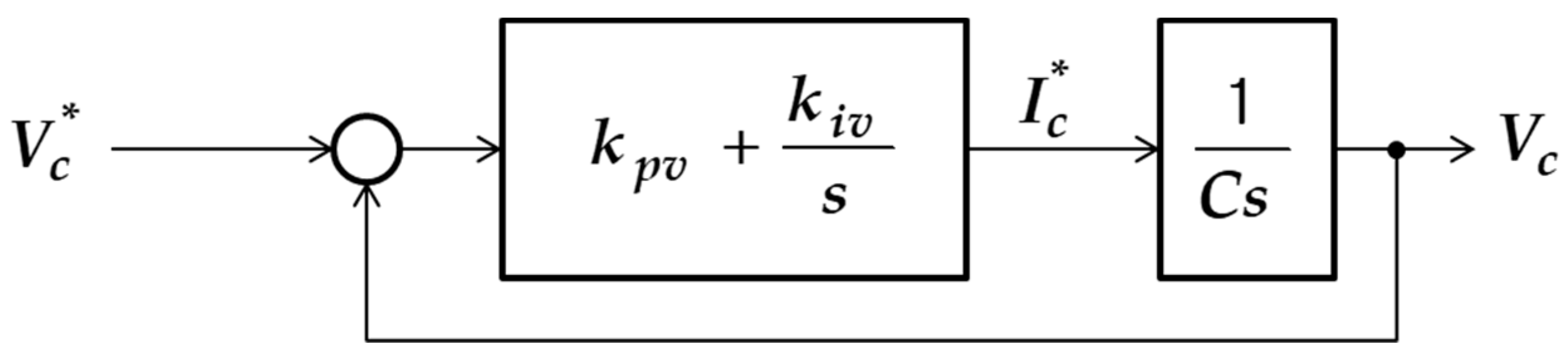
Figure 8.
Block diagram for voltage control for charging and discharging.

Figure 9.
Control sequence in case of leg fault: (a) Normal; (b) 1-Leg Fault; (c) 2-Leg Fault.
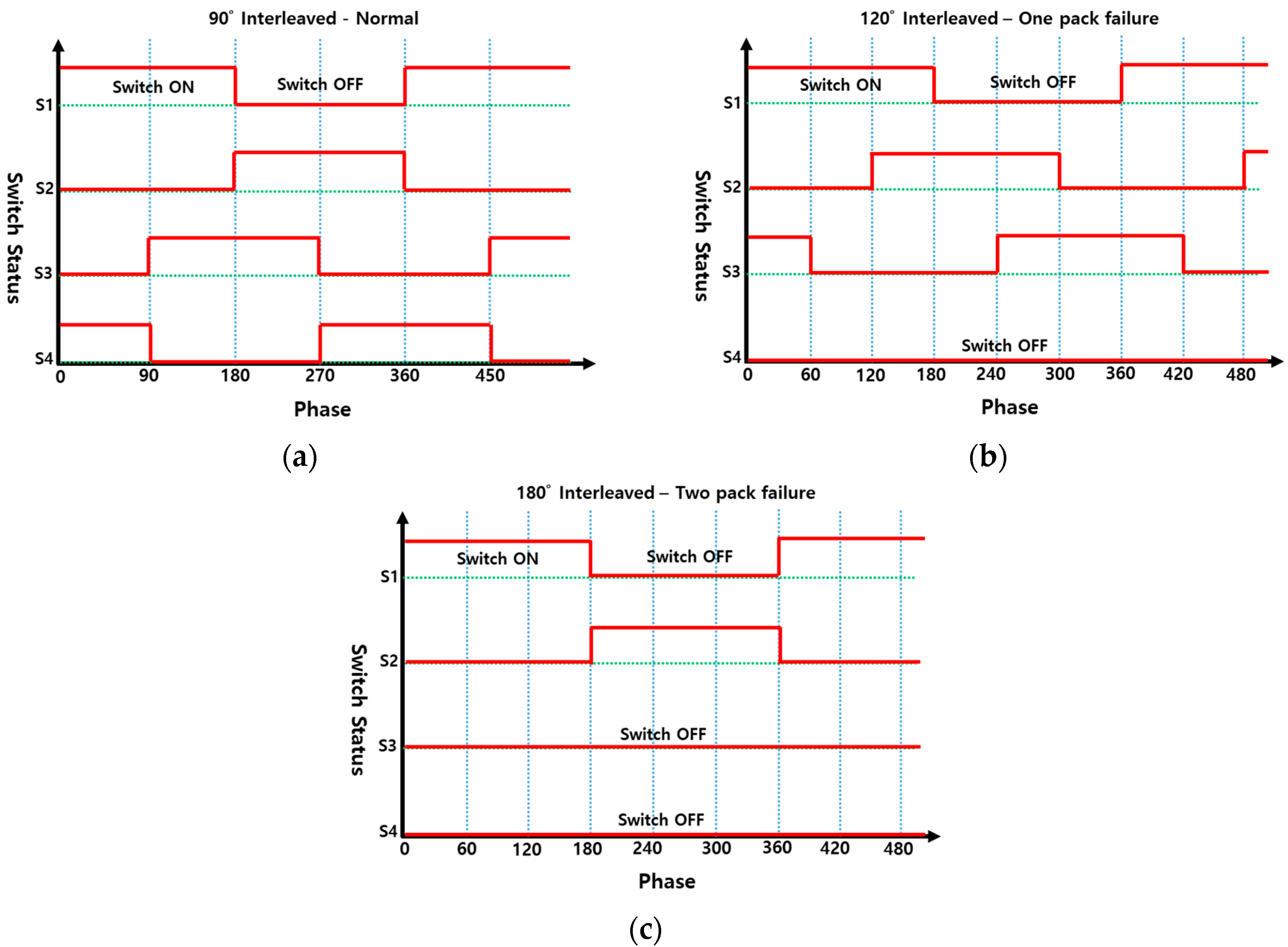
Figure 10.
Bypassing a faulty module using module bypass.
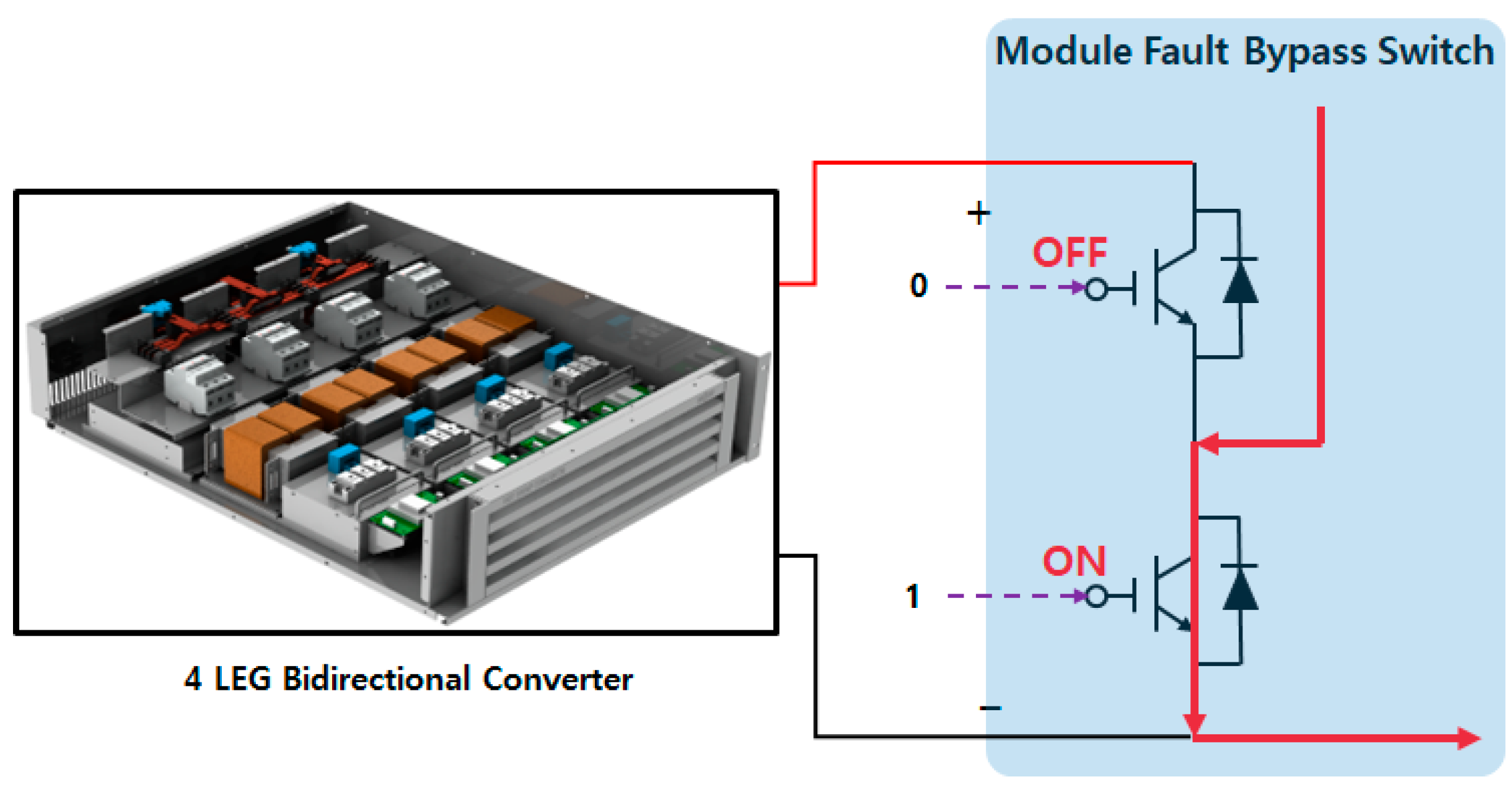
Figure 11.
Flow chart of module bypass control algorithm for converter hot-swap.
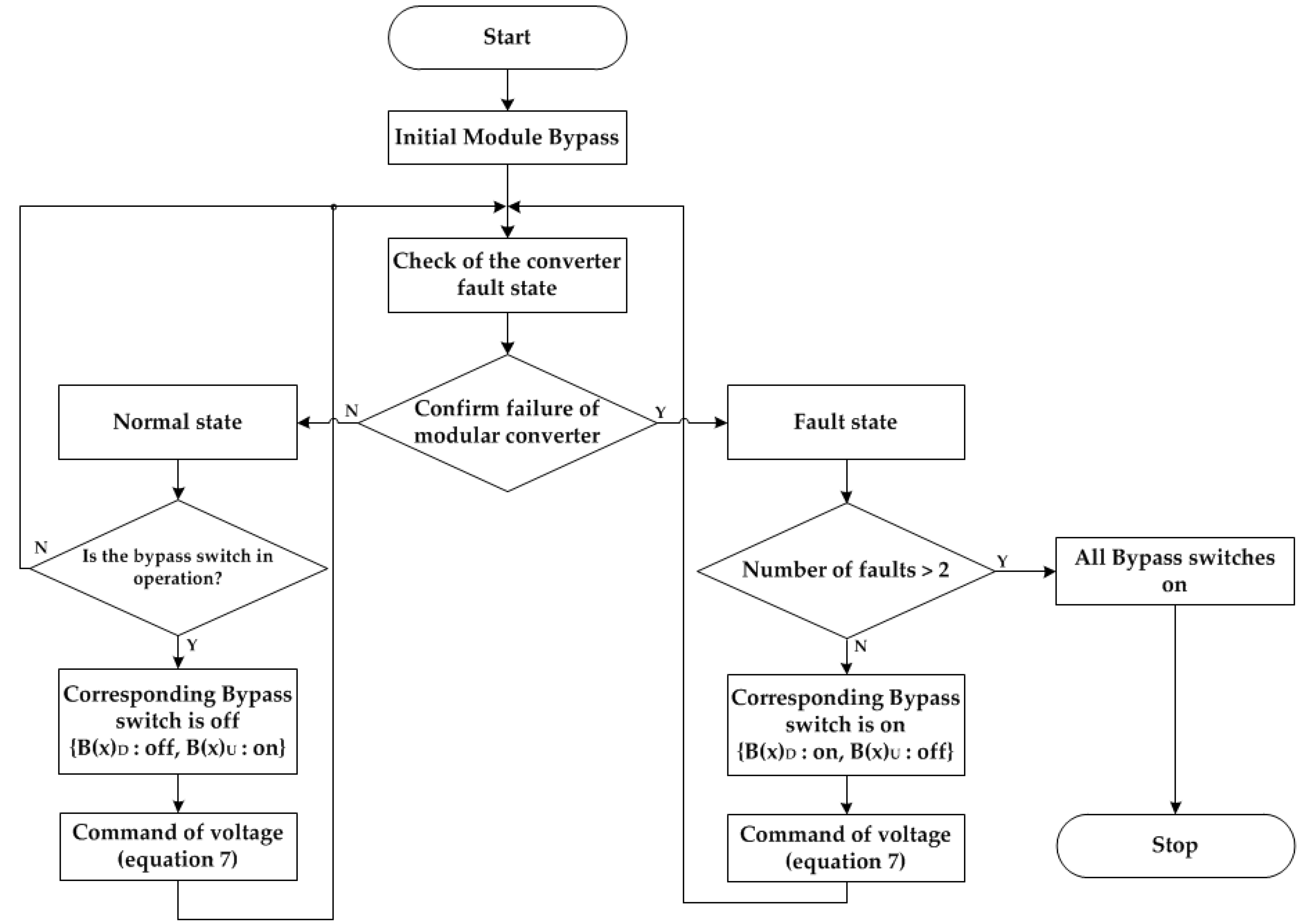
Figure 12.
Test setup for the proposed modular converter: (a) Experimental set; (b) Configuration of the experimental setup.
Figure 12.
Test setup for the proposed modular converter: (a) Experimental set; (b) Configuration of the experimental setup.
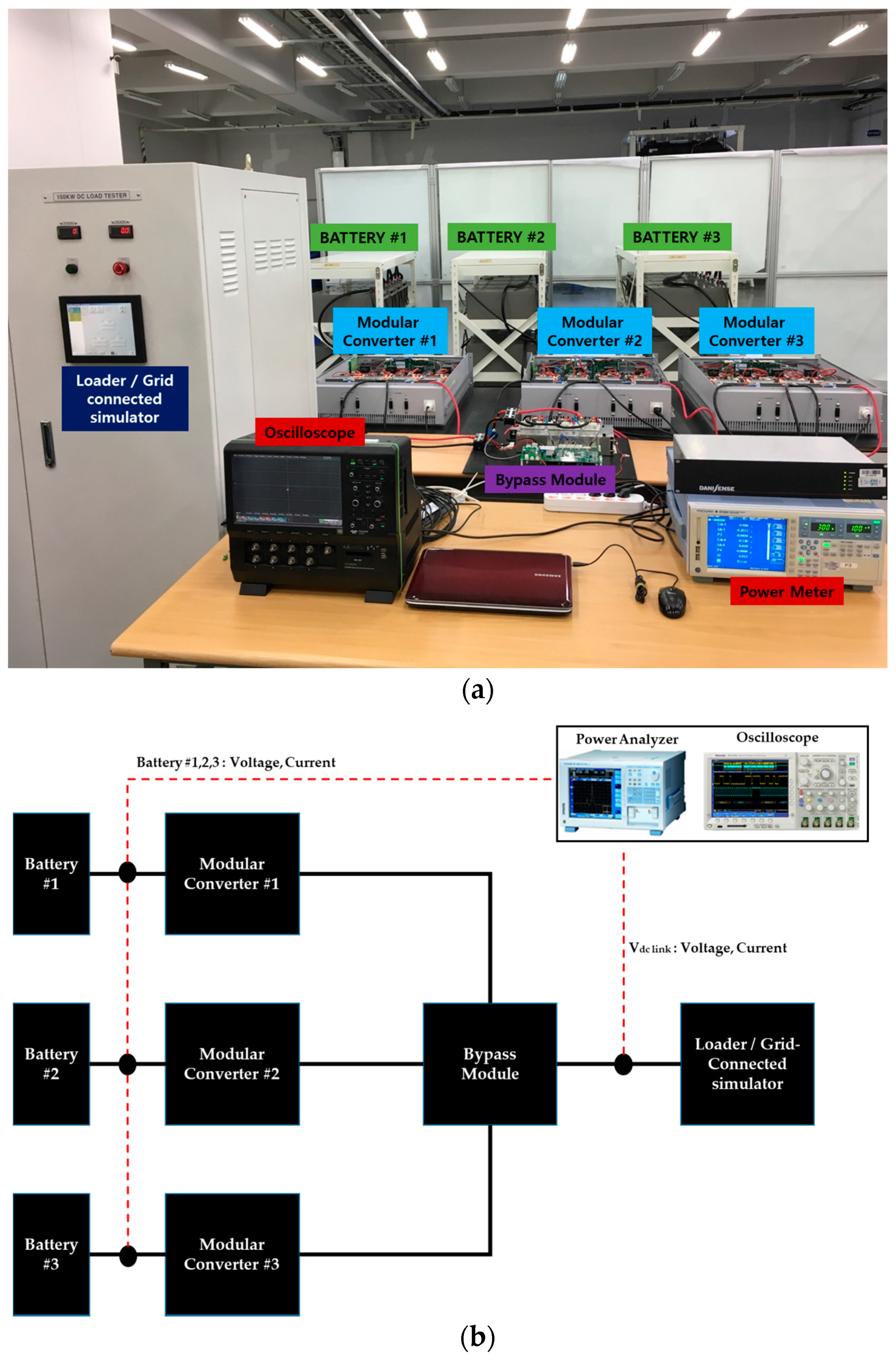
Figure 13.
Response waveforms of four-leg converter: (a) Charge mode; (b) Discharge mode.
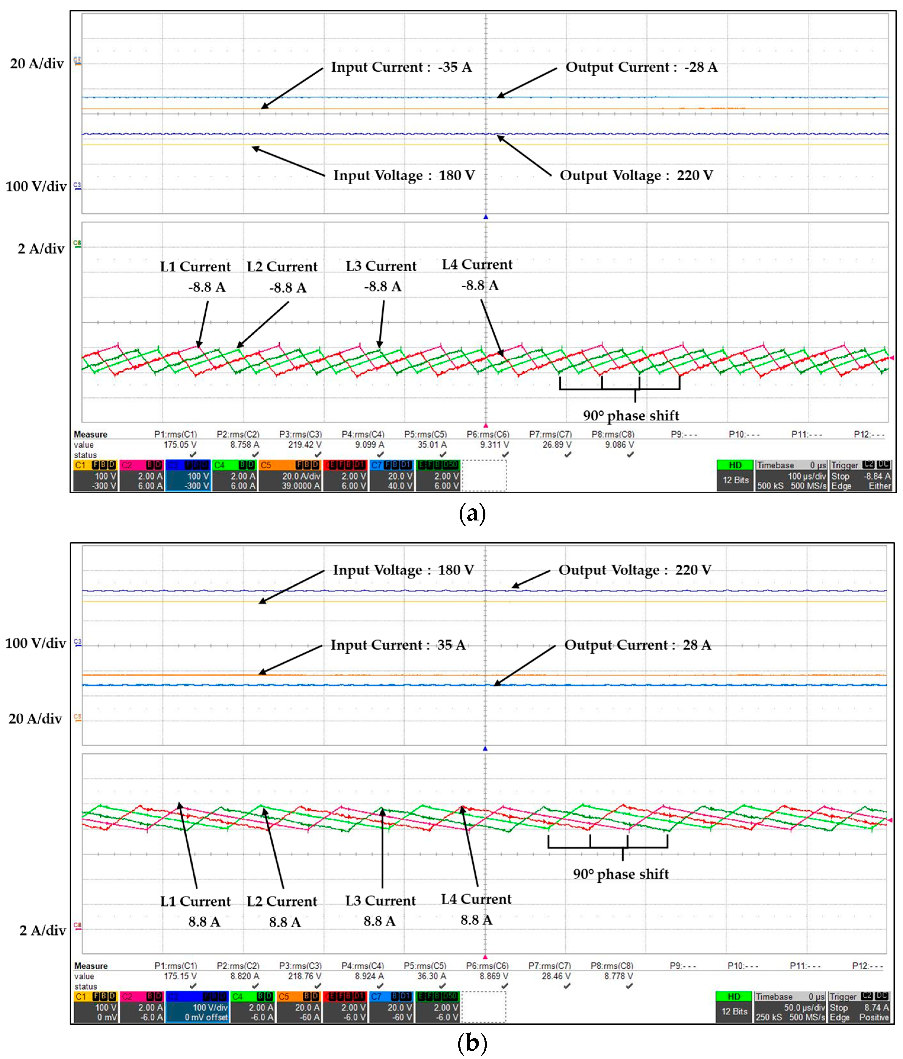
Figure 14.
Efficiency of four-leg converter: (a) Charge mode; (b) Discharge mode.
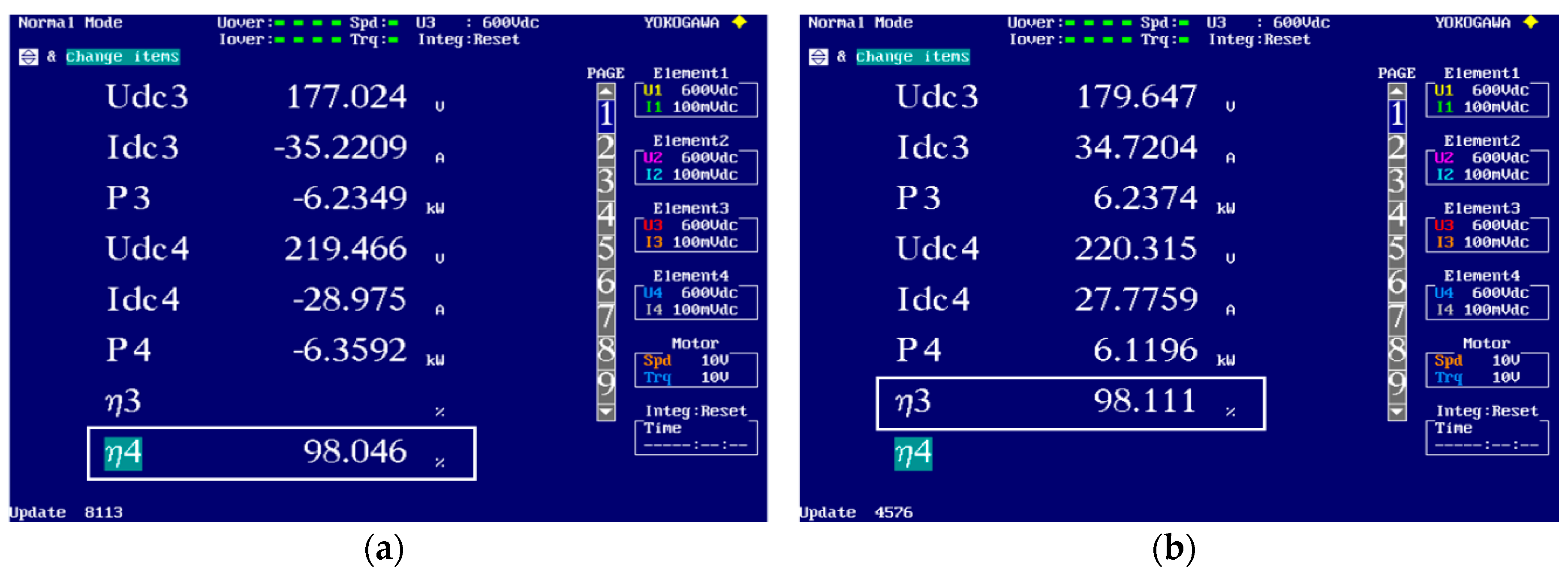
Figure 15.
Response waveforms in the hot-swap test for the single modular converter in the charge mode: (a) One faulty leg; (b) Two faulty legs.
Figure 15.
Response waveforms in the hot-swap test for the single modular converter in the charge mode: (a) One faulty leg; (b) Two faulty legs.
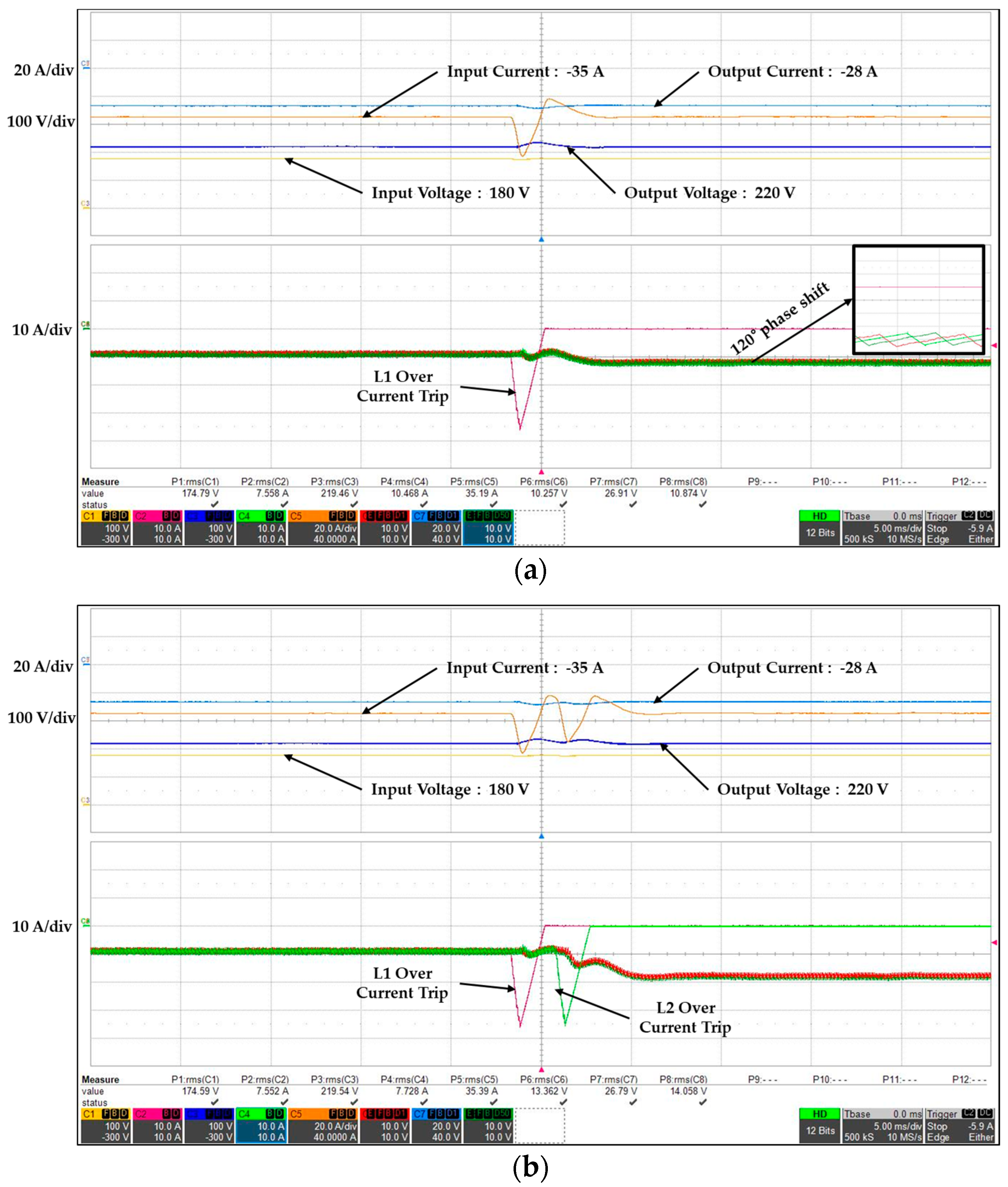
Figure 16.
Response waveforms in the hot-swap test for the single modular converter in the discharge mode: (a) One faulty leg; (b) Two faulty legs.
Figure 16.
Response waveforms in the hot-swap test for the single modular converter in the discharge mode: (a) One faulty leg; (b) Two faulty legs.

Figure 17.
Response waveforms for the return to normal mode in legs of the single modular converter: (a) Charge mode; (b) Discharge mode.
Figure 17.
Response waveforms for the return to normal mode in legs of the single modular converter: (a) Charge mode; (b) Discharge mode.

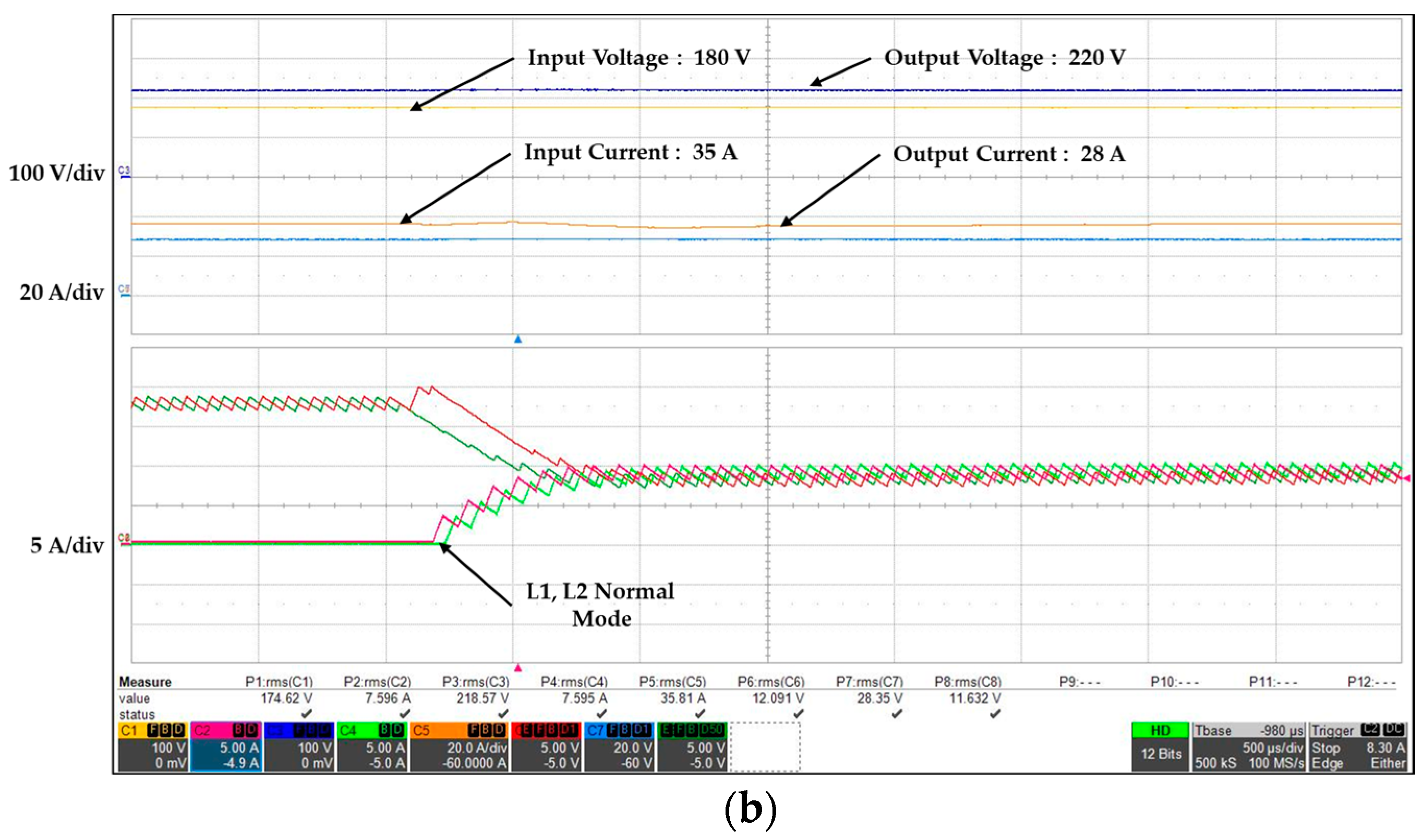
Figure 18.
Response waveforms according to battery SOC value at the charge mode of the modular converter: (a) Each battery with the same SOC; (b) Each battery with different SOC.
Figure 18.
Response waveforms according to battery SOC value at the charge mode of the modular converter: (a) Each battery with the same SOC; (b) Each battery with different SOC.


Figure 19.
Output power according to battery SOC at the charge mode of the modular converter: (a) Each battery with the same SOC; (b) Each battery with different SOC.
Figure 19.
Output power according to battery SOC at the charge mode of the modular converter: (a) Each battery with the same SOC; (b) Each battery with different SOC.

Figure 20.
Response waveforms according to battery SOC value at the discharge mode of the modular converter: (a) Each battery with the same SOC; (b) Each battery with different SOC.
Figure 20.
Response waveforms according to battery SOC value at the discharge mode of the modular converter: (a) Each battery with the same SOC; (b) Each battery with different SOC.
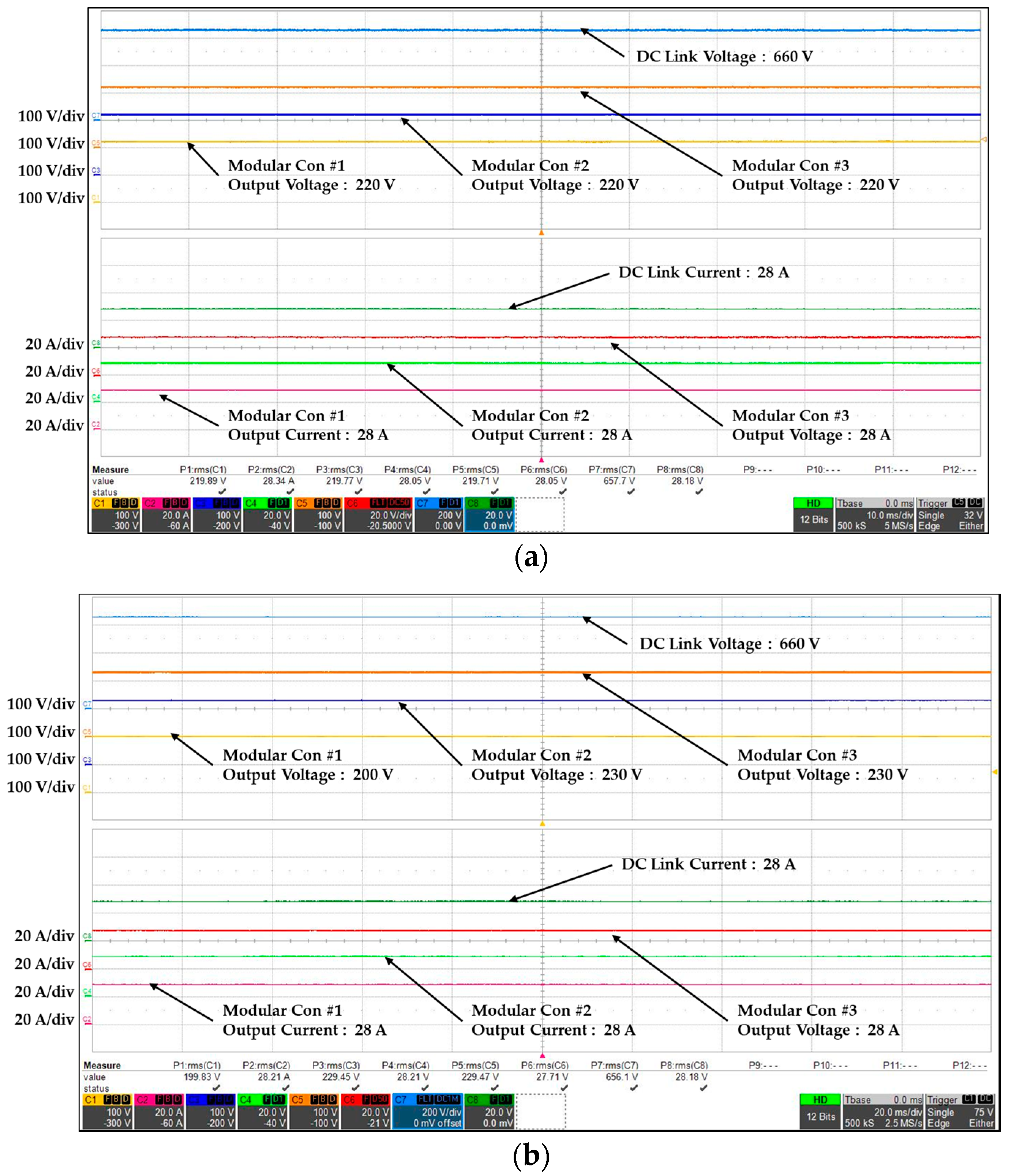
Figure 21.
Output power of the modular converter in discharge mode according to battery SOC: (a) Each battery with the same SOC; (b) Each battery with different SOC.
Figure 21.
Output power of the modular converter in discharge mode according to battery SOC: (a) Each battery with the same SOC; (b) Each battery with different SOC.

Figure 22.
Response waveforms of the hot-swap test for the modular converter system in battery charge: (a) Fault of the modular converter; (b) Return to normal mode of the modular converter; (c) Efficiency of the modular converter for hot-swap.
Figure 22.
Response waveforms of the hot-swap test for the modular converter system in battery charge: (a) Fault of the modular converter; (b) Return to normal mode of the modular converter; (c) Efficiency of the modular converter for hot-swap.

Figure 23.
Response waveforms of the hot-swap test for the modular converter system in battery discharge: (a) Fault of the modular converter; (b) Return to normal mode of the modular converter; (c) Efficiency of the modular converter for hot-swap.
Figure 23.
Response waveforms of the hot-swap test for the modular converter system in battery discharge: (a) Fault of the modular converter; (b) Return to normal mode of the modular converter; (c) Efficiency of the modular converter for hot-swap.

Table 1.
Test parameters.
| Parameter | Value | Parameter | Value |
|---|---|---|---|
| Input voltage | 165–190 V | Switching | 10 kHz |
| DC link voltage | 660 V | DC reactor | 2 mH |
| Modular converter power | 6 kW | Input capacitance | 1000 μF |
| Converter overdrive ratio | 150% | Output capacitance | 1000 μF |
© 2018 by the authors. Licensee MDPI, Basel, Switzerland. This article is an open access article distributed under the terms and conditions of the Creative Commons Attribution (CC BY) license (http://creativecommons.org/licenses/by/4.0/).
Share and Cite
MDPI and ACS Style
Cha, D.-S.; Choi, J.-S.; Oh, S.-Y.; Ahn, H.-J.; Lim, Y.-C. Hot-Swappable Modular Converter System Control for Heterogeneous Batteries and ESS. Energies 2018, 11, 309. https://doi.org/10.3390/en11020309
AMA Style
Cha D-S, Choi J-S, Oh S-Y, Ahn H-J, Lim Y-C. Hot-Swappable Modular Converter System Control for Heterogeneous Batteries and ESS. Energies. 2018; 11(2):309. https://doi.org/10.3390/en11020309
Chicago/Turabian StyleCha, Dae-Seak, Jung-Sik Choi, Seung-Yeol Oh, Hyun-Jin Ahn, and Young-Cheol Lim. 2018. "Hot-Swappable Modular Converter System Control for Heterogeneous Batteries and ESS" Energies 11, no. 2: 309. https://doi.org/10.3390/en11020309
Note that from the first issue of 2016, this journal uses article numbers instead of page numbers. See further details here.