Design and Optimization of a Brushless Wound-Rotor Vernier Machine

Department of Electronic Systems Engineering, Hanyang University, Ansan 15588, Korea
*
Author to whom correspondence should be addressed.
Energies 2018, 11(2), 317; https://doi.org/10.3390/en11020317
Submission received: 3 January 2018
/
Revised: 24 January 2018
/
Accepted: 29 January 2018
/
Published: 2 February 2018
(This article belongs to the Section I: Energy Fundamentals and Conversion)
Abstract
:In this paper, a permanent magnet (PM)-less, brushless, wound-rotor vernier machine (BL-WRVM) is proposed for variable speed applications such as electric vehicles and washing machines. The wound rotor is excited through an already existing brushless topology, which requires a dual inverter configuration to generate an additional subharmonic component in the stator magnetomotive force (MMF). Different from permanent magnet vernier machines (PMVMs), the proposed BL-WRVM provides easy regulation of the rotor flux for variable speed operation. A 24-slot, 4-pole stator, and 44-pole outer rotor were designed, and 2D finite element analysis (FEA) was carried out to determine the performance of the proposed machine. To improve the performance of the proposed machine, optimization of the rotor and stator winding turns was done. The optimized model was further analyzed for wide-speed operation, and its performance was then compared with that of an equivalent permanent magnet vernier machine (PMVM). The proposed machine has the advantage of low cost due to its PM-less structure and is suitable for variable speed applications.
1. Introduction
In recent years, permanent magnet vernier machines (PMVMs) have attracted a lot of interest due to their increasing demand in direct-drive applications. Their capability of achieving high torque at low speeds has distinguished them from other permanent magnet machines. Also, due to their electromagnetic gearing phenomenon, they can replace noisy and inefficient mechanical gearing systems. However, they have some limitations due to their low power factor, limited high-speed operation, and fluctuating high cost due to their PM.
PMVMs have rarely been used for variable-speed applications due to their significant core losses at high speed. Moreover, at high speed, the reactance of the machine increases more than does the back electromotive force (EMF), which also increases the inverter limit [1]. In [2], the maximum torque characteristics of vernier PM motors under adjustable speed operation were evaluated. In [3], a PMVM machine was designed for the practical variable-speed application of washing machines, and related challenges have been discussed. Hybrid PMVMs (HPMVMs) were brought forward to empower the PMVM for flux control of the PM for variable-speed operation. A new parallel hybrid PMVM was proposed in [4] to realize the bidirectional flux regulation capability by adjusting the DC current in the field winding. In [5], two new hybrid-excited PMVMs were proposed with all their excitation sources on the stator, which helps to control the temperature rise of magnets. However, it was concluded that PMVMs are not suitable for variable-speed applications, and, therefore, PMVM machines are generally used for low-speed direct-drive applications. Another issue associated with PMVMs is their high cost due to the use of rare-earth permanent magnets.
Vernier reluctance machines (VRMs) are PM-free vernier machines [6]. VRMs have lower torque density than PMVMs and a poor power factor. To improve the torque density of VRMs, direct current vernier reluctance machines (DC-VRMs) were presented, in which field windings were placed on the stator to improve the robustness and lower the cost [7,8,9]. However, this resulted in a high saturation level in the stator. Moreover, due to both armature winding and field winding on the stator, the fill factor and current density of the armature winding are limited. To solve these problems, in [10], a wound-rotor vernier machine was introduced, in which field windings were placed on the rotor instead of the stator. This machine will have better saturation levels, but will also face problems in the maintenance of the brushes and slip-rings required for excitation of the rotor.
In [11], a brushless topology was presented for a wound-rotor synchronous machine (WRSM). A rotating magnetomotive force (MMF) is generated from two inverters. This contains a fundamental and an additional subharmonic component for brushless rotor excitation. Brushes and slip-rings create the problem of sparking and require regular maintenance, but these issues are solved by brushless operation.
In this paper, a brushless wound-rotor vernier machine (BL-WRVM) is proposed for variable-speed applications. The cost of the machine is lower than that of PMVMs due to its PM-less structure. The field flux of the machine is easily controlled, and, therefore, the speed of the machine can be increased. The field winding is on the rotor, which avoids the issues of DC-VRM. Moreover, the brushless topology avoids the problems of sparking and regular maintenance in rotor-current-excited vernier machines. Hence, the machine combines the advantages of brushless WRSM machines and PM-less vernier machines in a single topology, which was analyzed for variable-speed applications.
The remainder of this paper is structured as follows. In the second section, the applied brushless topology [11] and the proposed vernier machine configuration are discussed. In the third section, the design of the proposed machine and 2D finite element analysis (2D-FEA) simulation for the basic model are discussed. In the fourth section, the optimization and sensitivity analysis are discussed. In the fifth section, the wide-speed operation of the proposed machine and its comparison with an equivalent PMVM are discussed. Finally, conclusions are drawn.
2. Brushless Wound-Rotor Topology and Proposed Configuration
In this section, the applied brushless topology [11] is discussed, and its working principle is explained. The proposed vernier machine configuration is then discussed.
2.1. Brushless Wound-Rotor Topology
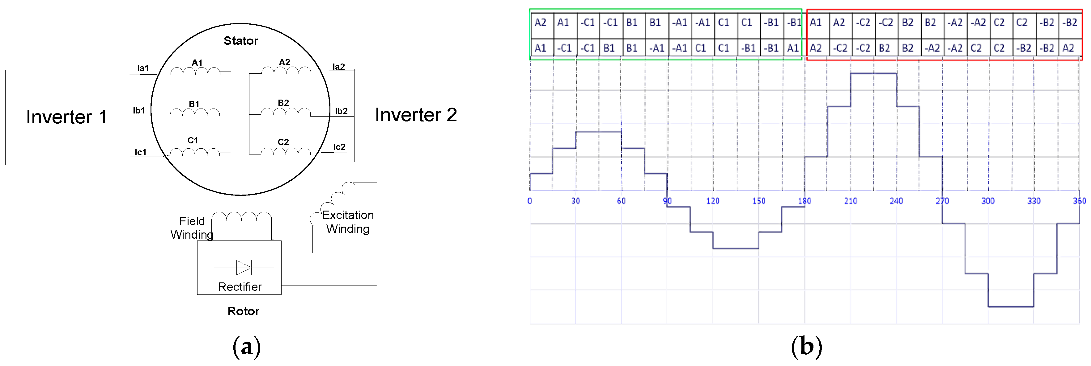
The topology for brushless subharmonic excitation is shown in Figure 1a [11]. Each phase of stator winding is divided into two portions of coil groups. One portion is supplied current through “Inverter 1”, which has a higher magnitude of current, whereas the other portion is supplied current through “Inverter 2”, which has a lower magnitude. The frequency and phase differences are the same for both inverters. Only the difference in magnitudes of currents in different coil groups is used to generate the required MMF, which embodies both the fundamental and the subharmonic components.
For the case of the rotor, two separate windings—excitation winding and field winding—are placed. The excitation winding is a special winding that links with the subharmonic component of the stator MMF. It induces voltage from the subharmonic component of the stator MMF. This induced voltage is rectified through a rotating rectifier and fed to the rotor field winding. In this way, the brushless excitation process is completed. The diode bridge rectifier circuit is placed on the rotor between the two rotor windings.
The winding distribution for the machine is flattened and shown in Figure 1b, along with the stator MMF. The waveform has two different portions. For the first 180 mechanical degrees, the MMF has smaller maximum and minimum values due to the smaller current fed into the windings (A1, B1, and C1). For 180–360 mechanical degrees, the MMF waveform has larger maximum and minimum peaks due to the higher current magnitude fed to the windings (A2, B2, and C2). The composite MMF has two dominant components: the fundamental component with frequency f and the subharmonic component with frequency f/2.
The subharmonic component has a different rotating speed from the fundamental synchronous speed, and can be calculated by Equation (1):
where is the rotating speed of the harmonic component, is the fundamental synchronous speed, is the harmonic number (which in this case is 1/2 or 0.5), f is the supplied frequency, and is the number of poles. From this equation, we can conclude that the subharmonic component (with half the frequency of the fundamental) will rotate at a speed twice as high as the fundamental synchronous speed. This different speed helps the harmonic component to get induced in the rotor harmonic winding.
The Fourier series components for the MMF for a 4-pole, 24-slot machine having a coil span of 5 is represented in Equation (2):
f(x) = −1.544cos(x) + 5.345sin(2x) + 0.87cos(3x) + 0.1816cos(5x) + 0.06317cos(7x) + 0.00858cos(9x) + 0.076sin(10x) + 0.0176cos(11x) − 0.0150cos(13x) + 0.0548sin(14x) + …
This equation shows the different frequency components in the MMF. The fundamental component has an amplitude of 5.345, and the subharmonic component has an amplitude of 1.544. The remaining terms in Equation (2) are all the odd order harmonics of the subharmonic component, and the 5th, 7th, and 11th order harmonics of the fundamental component. The harmonic contents are shown in Figure 2.
2.2. Proposed Vernier Machine Configuration
In [11], the brushless topology was implemented for the synchronous machine. For this paper, a similar topology was implemented for outer rotor vernier machines. Vernier machines have a higher torque density than synchronous machines and are used to replace mechanical gearing systems. The outer rotor is suitable for applications like washing machines and in-wheel motors. It also offers greater slot area for rotor windings. An inner rotor configuration can be implemented as well.
To apply the topology of [11] for a vernier machine, proper combinations of stator slots (), stator pole pairs (), rotor slots (), rotor field winding pole pairs (), and rotor excitation winding pole pairs () are required. For the machine to work in vernier mode, it must satisfy Equation (3):
For the proposed BL-WRVM, the and are kept similar to those in [11], i.e., 24 slots and 4 poles, generating the required stator MMF for the brushless topology. Here, is equal to 22, justifying (3), and is equal to 1, which induces the subharmonic component from the stator MMF.
According to this pole–slot combination, when the stator windings are excited by the dual inverter topology of [11], composite MMF is generated to form a 4-pole component and a 2-pole component. The 2-pole component is linked with the excitation winding on the rotor, and voltage is induced in this winding. This induced voltage is rectified through the rotating rectifier on the rotor. The rectified DC current is supplied to the rotor field finding, which generates 22-pole pairs. Now, the 4-pole component of the stator MMF and 22-pole pair rotor field windings are linked through the vernier operation to generate the required torque of the machine.
3. Design and Performance of Proposed BL-WRVM
3.1. Design Considerations
Apart from selecting the proper slot–pole combination for the proposed machine, which satisfies the vernier principle and uses brushless operation, a further proper pole ratio, defined as the ratio of rotor pole pairs to stator pole pairs, was also considered in the design of the proposed BL-WRVM. The pole ratio of the current pole–slot combination is 11. A low pole ratio generally results in low torque density, whereas a very high pole ratio results in low torque density due to high leakage flux [12]. Therefore, a pole ratio of 11 is a reasonable choice. Moreover, it has been observed that the brushless operation increases the torque ripple of the machine [11]; therefore, the least common multiple (LCM) of the stator slots and rotor pole pairs, which plays a significant role in the cogging torque of the machine, was also considered in the machine design.
The split ratio (i.e., the ratio of rotor inner diameter to rotor outer diameter) was also examined in the machine design. A higher split ratio usually results in a higher torque density; however, the fill factor of the rotor and saturation of the rotor core limit this value. A split ratio of 0.79 was initially selected.
The stator slot opening ratio (i.e., the stator slot opening width to slot pitch) plays a significant le in the torque density of the vernier machine. After parametric results from FEA, this value was chosen as 0.65 for the stator and 0.5 for the rotor.
3.2. Performance Analysis
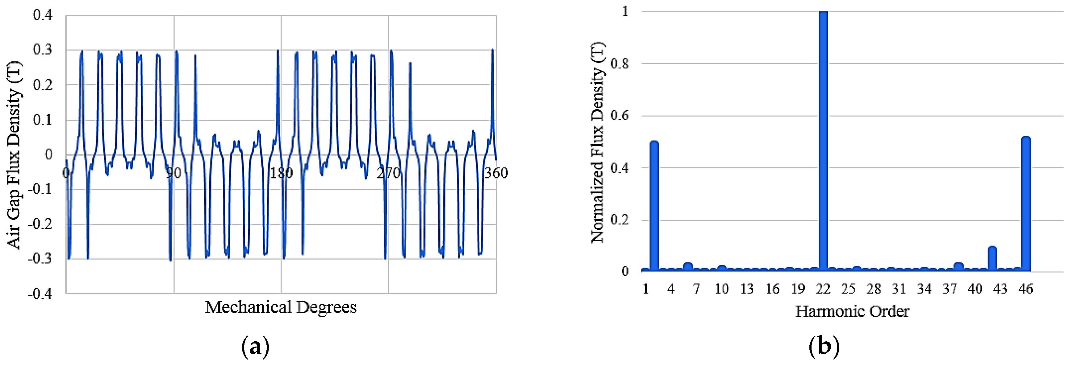
This section presents the performance analysis of the proposed BL-WRVM’s basic model. 2D-FEA simulations were conducted by Ansys Maxwell (2016). The no-load airgap flux density plot is shown in Figure 4a. The harmonic order for the normalized flux density is shown in Figure 4b. It demonstrates 22-pole pairs for the rotor field winding and its 2-pole pair and 46-pole pair components. However, the stator windings have 2-pole pairs. Therefore, the machine is functioning as a vernier and producing torque due to the “magnetic gearing” effect of a vernier machine.
For the no-load operation, the back EMF is shown in Figure 5a, for 5 A DC current in the field winding. The root mean square (rms) value of the back EMF is 49.34 V. Also, the back EMFs in all three phases are balanced.
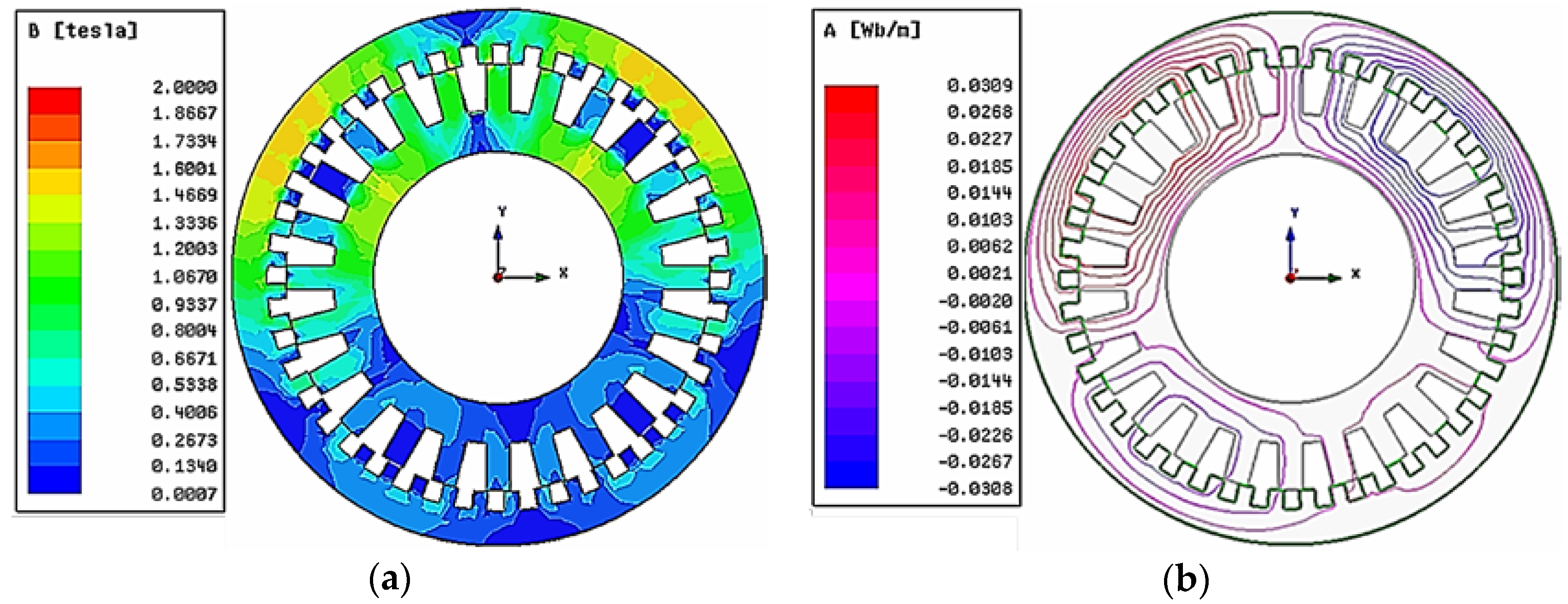
For the load operation, the machine is being excited by a 1 A (rms) armature current (1.33 A for high-current coils and 0.66 A for low-current coils for an average of 1 A). The electromagnetic torque of the model is shown in Figure 5b. The average value of the torque is 18.33 Nm with a ripple of 49%. Figure 6a shows the flux density, and Figure 6b shows the flux lines plots for the loaded case. It shows that the machine is well under the saturation level. The upper portion of the machine shows higher flux density and a greater concentration of flux lines compared with the lower portion due to the placement of coils with higher current magnitude, which is necessary to produce the subharmonic component.
The performance of the basic model is summarized in Table 2. The power factor (PF) for the machine is 0.28, and efficiency is 55%, which is quite low. The low efficiency is caused by the additional copper losses in the rotor windings. The PF is low because of the increased inductance of the machine due to additional excitation winding on the rotor. Also, the machine has a high torque ripple of 49% due to the subharmonic component in the air gap, which is necessary for brushless operation. In following section, the numbers of stator and rotor winding turns are optimized to achieve a better power factor and efficiency while the torque ripple is decreased.
4. Machine Sensitivity Analysis and Optimization
4.1. Sensitivity Analysis
In [13], the effects of varying the stator winding and rotor winding turns on machine performance are discussed. Considering that, three parameters have been optimized to improve the proposed machine’s performance: the number of stator winding turns, field winding turns, and excitation winding turns. The main objective of the design optimization of the basic model is to decrease the torque ripple and to improve the power factor and efficiency without reducing the output torque. First, a sensitivity analysis was performed to observe the effects of varying the number of turns of field winding, excitation winding, and stator winding on the output performance of the machine. Then, based on the sensitivity analysis, constraints and ranges for the design variables were selected for optimization of the BL-WRVM to reduce the torque ripple and improve the power factor of the machine.
4.1.1. Effect of Variation of Field Winding Turns on the Machine Performance
Figure 7 shows the effect of variation of the number of turns of the field winding on the output performance of the BL-WRVM. The field winding turns are varied from 12 turns/slot to 54 turns/slot, keeping the number of turns of the stator and excitation windings the same as the basic model of the machine. Due to the increase in the number of the field winding turns, the magnetic loading of the machine is increased, which results in an increase in the machine’s torque, as shown in Figure 7a. Figure 7b shows that the torque ripple of the machine is decreased with the increase in number of the field winding turns. Figure 7c shows the variation in efficiency with the increase of the number of field winding turns of the machine. The efficiency of the machine exhibits a small variation from 12 turns/slot to 40 turns/slot. However, when the field winding turns are increased above 40 turns/slot, the efficiency of the machine is decreased due to increased copper losses in the rotor windings. The effect of the variation of field winding turns on PF is shown in Figure 7d. The power factor of the machine is improved with the increase in field winding turns due to enhanced magnetic loading.
The performance of the machine is improved by increasing the number of field winding turns of the BL-WRVM. However, due to the limitation of the slot fill factor and the power of the machine, 36 turns/slot for the field winding was selected as the optimal number. Further analysis of the machine was carried out by keeping the field winding turns/slot equal to 36. This increase in field winding turns requires more rotor slot area to keep the slot fill factor under 50%. Therefore, to adjust these turns, the rotor slot area was increased by increasing the rotor outer diameter from 300 mm to 315 mm.
4.1.2. Effect of Variation of Excitation Winding Turns on the Machine Performance
The effect of varying the number of turns of the excitation winding on the output performance of the BL-WRVM is shown in Figure 8. The excitation winding turns were varied from 6 turns/slot to 24 turns/slot, thus keeping the number of turns of the stator winding the same as in the basic model of the BL-WRVM. However, the field winding has 36 turns/slot, as discussed above. As the number of turns are increased for the rotor excitation winding, its induced voltage due to the stator MMF subharmonic component is increased, while the corresponding excitation winding current is reduced to maintain the constant power. Consequently, the main field current supplied to the field winding is decreased, which results in a decrease in the output torque of the machine, as shown in Figure 8a. Figure 8b shows the variation of the torque ripple with the increase in the excitation winding turns. The torque ripple of the machine is increased. Figure 8c shows that the efficiency of the machine is increased with the increase in the number of excitation winding turns. The improvement in efficiency is due to the decreased copper losses in the rotor field winding. Figure 8d shows the effect of the variation of the excitation winding turns on the power factor of the machine. The power factor is decreased due to the decrease in the magnetic loading of the machine.
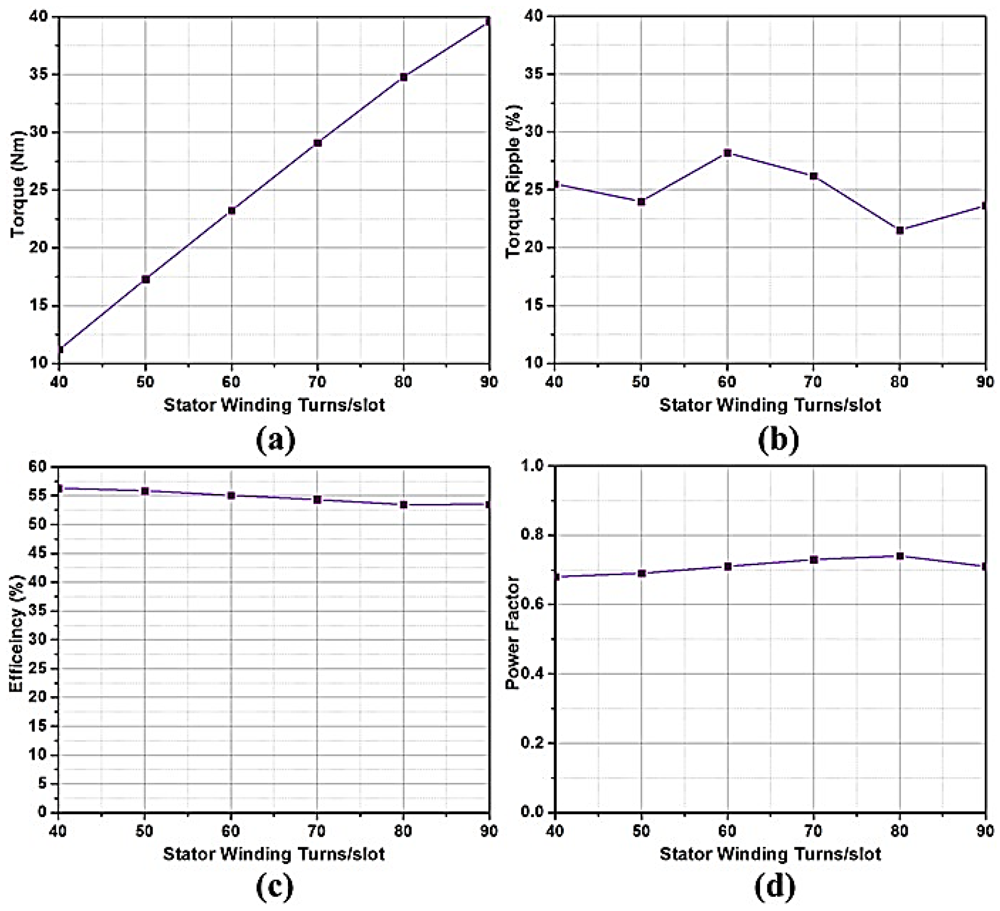
4.1.3. Effect of Variation of Stator Winding Turns on the Machine Performance
Figure 9 depicts the effect of changing the number of turns of the stator winding on the output performance of the BL-WRVM. The stator winding turns are varied from 90 turns/slot to 40 turns/slot, while keeping the number of turns/slot of excitation winding the same as in the basic model (6 turns/slot) and the field winding equal to 36 turns/slot. The electric loading of the machine is increased with the increase in the number of stator winding turns, which results in an increase in the machine’s output torque, as shown in Figure 9a. Figure 9b shows the variation in the torque ripple due to a change in the turns of stator winding. Figure 9c shows the effect of the variation in the number of stator winding turns on the machine’s efficiency, which is slightly reduced due to the increased copper losses. Figure 9d shows that the effect of the change of stator winding turns on the power factor of the machine is quite small.
4.2. Design Optimization
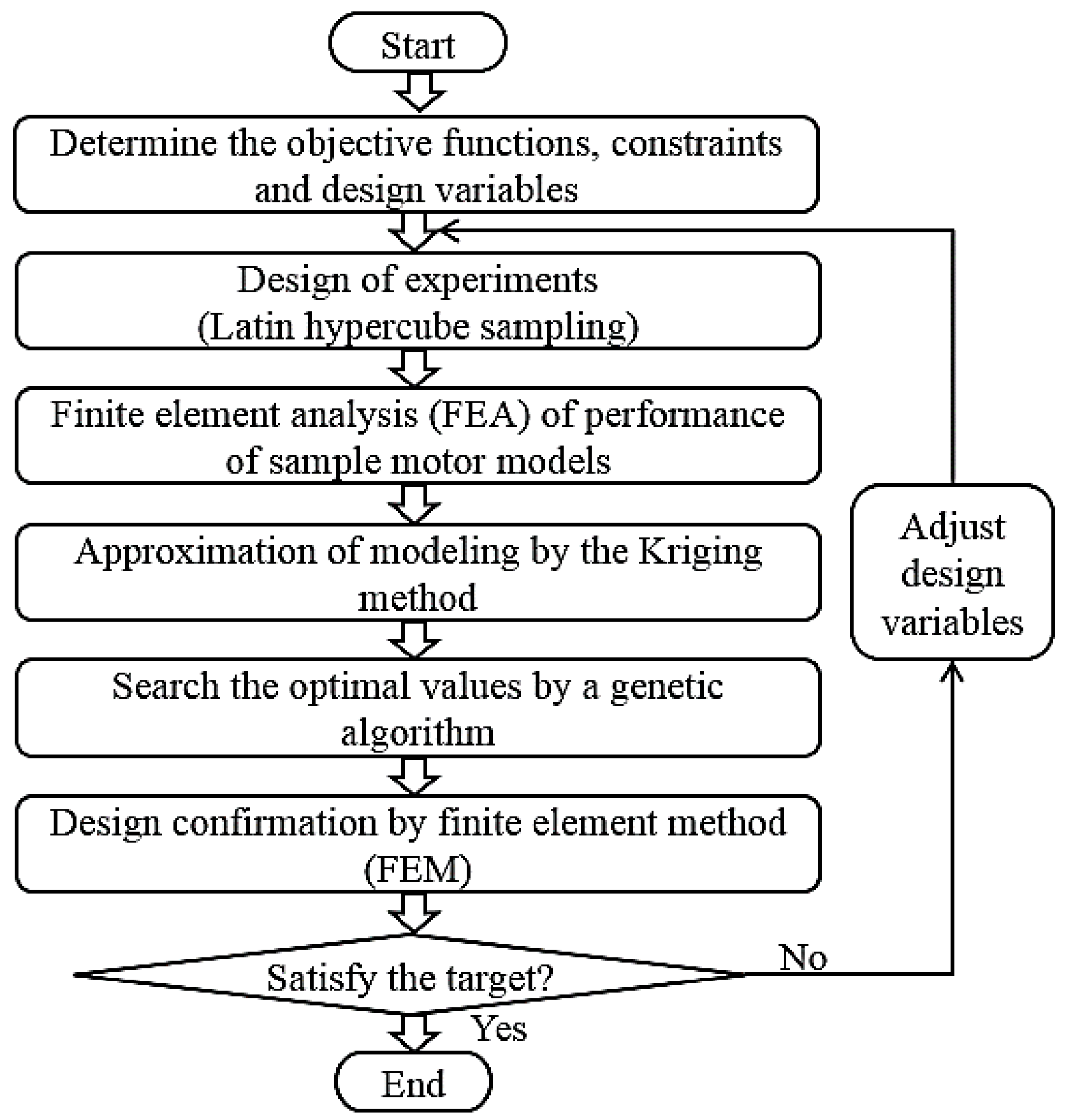
To improve the power factor and decrease the torque ripple, the optimization was applied on the proposed BL-WRVM using the kriging method and a genetic algorithm (GA). Based on the sensitivity analysis performed on the basic model, two design variables—excitation winding turns/slot and stator winding turns/slot —were selected. The optimal design process is shown in Figure 10. First, the objective functions, constraints, and design variables were obtained. Then the Latin hypercube sampling method was applied to select the sampling points in accordance with the design of the experiment process. The FEA was used to calculate the output performance for each model, and the kriging method was used for the approximation modeling. The GA evaluates the fitness from the modeling developed by the kriging method. Thus, the optimal results were determined by the population. Finally, the 2D FEA verified the optimal design results.
The objective functions for reducing the torque ripple and for maximizing the power factor are shown in (4). The constraints are set to keep the efficiency of the machine greater than 55% and keep the output torque greater than or equal to the torque of the basic model (18.33 Nm), as given in (5). The range of design variables, based on the sensitivity analysis discussed above, are given in (6).
- Objective functionMaximize the power factor
Minimize the torque ripple - ConstraintsEfficiency ≥ 55%
Torque ≥ 18.33 Nm - Design variables
In the optimization process, optimal values of the design variables were obtained as 8 turns/slot for the excitation winding and 60 turns/slot for the stator winding. The slot fill factor for the rotor was 41%, whereas the slot fill factor for the stator was 30%.
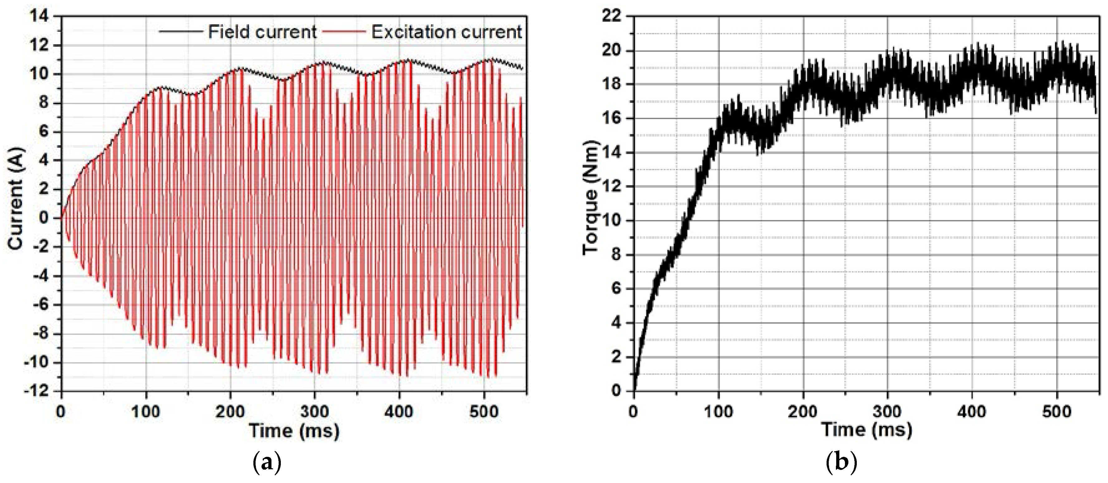
A 2D-FEA analysis of the optimized model was conducted. The induced currents in rotor excitation winding and rectified field current are shown in Figure 11a. The electromagnetic torque generated by the machine is plotted in Figure 11b. The flux density plot and the flux lines plot of the machine are shown in Figure 12a,b, respectively.
The overall performance comparison of the basic and optimized model of the BL-WRVM at the rated speed of 300 rpm is given in Table 3. The torque ripple of the optimized model of the BL-WRVM is decreased by 25.75% compared to the torque ripple of the basic model. Moreover, the power factor and the efficiency of the optimized model compared with basic model are improved almost by 54% and 6.66%, respectively.
As it can be seen in Figure 12, the lower part of the machine has lower flux density compared with the upper part due to the different stator current magnitudes. This unbalanced flux density will put additional stress on the bearings. The effect of unbalanced flux density can be minimized by incorporating an 8-pole or 16-pole stator.
5. Wide-Speed Operation and Performance Comparison
One of the main advantages of wound-rotor machines is that they can easily be used for high-speed applications because of their flexibility regarding the rotor field. For the case of PM rotor machines, the rotor field is mostly fixed. Generally, for PM machines to achieve high-speed operation, a negative d-axis current is provided to weaken the rotor flux, which requires an extra control strategy. In [14], the advantages of using wound-rotor synchronous machine for high-speed applications are discussed in comparison with PM machines. For the proposed machine, the high-speed operation is discussed in the following section.
5.1. Wide-Speed Operation
As noted, in the proposed BL-WRVM, the rotor field current is induced through the stator MMF subharmonic component. By regulating the stator MMF, the rotor field can easily be controlled. The high-speed operation for the brushless topology given here was discussed in [11]. It was based upon modifying the ratio of currents from two inverters.
In this paper, high-speed operation is realized by keeping the ratio of currents from two inverters constant at 2, while changing the rms value of currents from the two inverters with the same proportion. For the rated speed of 300 rpm, the rated currents for two inverters are 1.33 A and 0.66 A (ratio is 2). To move the machine from 300 to 600 rpm, the currents are changed to 0.9 A and 0.45 A, keeping the output power of the machine constant. As the stator armature current is reduced, the rotor field current is also reduced; hence, the rotor field is reduced to allow for the increase in the machine’s speed. By further reducing the stator armature currents from two inverters, the machine’s speed can be further increased. For our analysis, the machine was simulated up to 2400 rpm (8 times the base speed). The rotor field currents are shown in Figure 13. As the stator armature current and rotor field current are reduced for high-speed operation of the machine, the rotor copper loss is reduced. The machine core loss is increased as the machine moves into high-speed operation, but the overall efficiency of the machine is increased. Table 4 summarizes the performance of the machine at high-speed operation.
For speeds under the rated speed (300 rpm), the BL-WRVM achieves the required torque at 200 rpm, but as the speed further reduces to 100 rpm, the induced harmonic current decreases and results in low torque. To achieve constant torque at 100 rpm, we varied the ratio of currents in two portions of winding from 2 to 3. This increase in the current ratio helps to achieve the required torque at 100 rpm.
5.2. Performance Comparison with PMVM
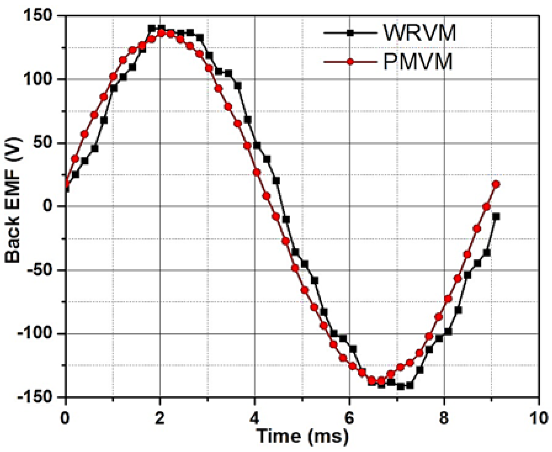
To get an idea of the performance of the proposed machine, its efficiency is compared with that of an equivalent PMVM at different speeds. The stators for both machines were kept the same, while for the rotor of PMVM, the slots and teeth were replaced by a PM material, NdFeB. The 2D model for the developed PMVM is shown in Figure 14. Magnetic loading for PMVM was the same as that of the proposed machine. The back EMF at 300 rpm for both the machines is given in Figure 15. The back EMF for the optimized BL-WRVM has been plotted providing the rated field current (10.56 A).
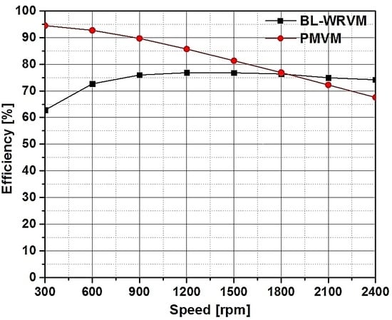
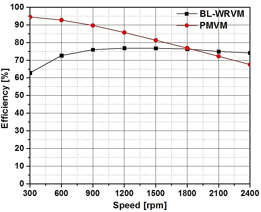
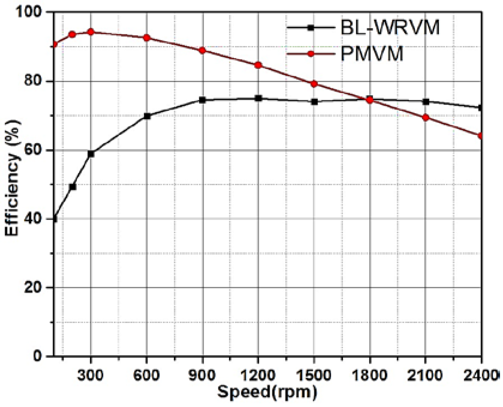
PMVM is simulated for wide-speed to compare its performance with that of the BL-WRVM. For the PMVM, the high-speed operation is achieved by using a negative d-axis method. The stator current and output power were kept fixed. Core loss and efficiency of the PMVM for wide-speed operation are shown in Table 5. For the low-speed operation, core loss of the PMVM is low; hence, its efficiency is high, but as we move toward high-speed operation, the core loss increases and the efficiency at 2400 rpm decreases to 64.13%.
Figure 16 shows the efficiency comparison between BL-WRVM and PMVM for wide-speed. For low speeds, the BL-WRVM shows lower efficiency as compared with PMVM, but as we move toward high-speed operation, the proposed BL-WRVM shows better efficiency.
6. Conclusions
In this paper, a BL-WRVM machine is proposed. The proposed machine has a PM-less structure and the advantage of easy air gap flux regulation for variable-speed applications. Sensitivity analysis and design optimization for the proposed machine considered the stator and rotor winding turns. Further, the proposed machine was simulated for wide-speed operation, and its efficiency was compared with that of an equivalent PMVM. The proposed machine shows better performance at high speed than does the PMVM.
Acknowledgments
This work was supported in part by the BK21PLUS Program through the National Research Foundation of Korea within the Ministry of Education, and in part by the National Research Foundation of Korea (NRF) grant funded by the Korea government (Ministry of Science) (No.NRF-2017R1A2B4007697).
Author Contributions
Noman Baloch conceived the idea and helped in design; Asif Hussain designed the basic model and performed the optimization; Qasim Ali performed the FEM simulations, analyzed and compared the results and wrote the paper; Byung il Kwon supervised the research throughout.
Conflicts of Interest
The authors declare no conflict of interest.
References
- Kim, B.; Thomas, A.L. Operation and Design Principles of a PM Vernier Motor. IEEE Trans. Ind. Appl. 2014, 50, 3656–3663. [Google Scholar] [CrossRef]
- Kim, B. Characteristic Analysis of a Vernier PM motor Considering Adjustable Speed Control. In Proceedings of the 2016 IEEE Conference and Expo Transportation Electrification Asia-Pacific (ITEC Asia-Pacific), Busan, Korea, 1–4 June 2016. [Google Scholar] [CrossRef]
- Kim, B.; Thomas, A.L. Design of a Surface PM Vernier Motor for a Practical Variable Speed Application. In Proceedings of the 2015 IEEE Energy Conversion Congress and Exposition (ECCE), Montreal, QC, Canada, 20–24 September 2015. [Google Scholar] [CrossRef]
- Li, W.; Ching, T.W.; Chau, K.T. A Hybrid-Excited Vernier Permanent Magnet Machine Using Homopolar Topology. IEEE Trans. Magn. 2017, 53. [Google Scholar] [CrossRef]
- Zhao, F.; Thomas, A.L.; Byung, I.K. A Novel Dual-Stator Axial-Flux Spoke-Type Permanent Magnet Vernier Machine for Direct-Drive Applications. IEEE Trans. Magn. 2014, 50. [Google Scholar] [CrossRef]
- Mukherji, K.C.; Tustin, A. Vernier reluctance motor. Proc. Inst. Electr. Eng. 1974, 121, 965–974. [Google Scholar] [CrossRef]
- Jia, S.; Qu, R.; Li, J.; Li, D.; Lu, X. Comparison of Stator DC Current Excited Vernier Reluctance Machines with Different Field Winding Configurations. IEEE Trans. Magn. 2017, 53. [Google Scholar] [CrossRef]
- Jia, S.; Qu, R.; Li, J.; Li, D. Principles of Stator DC Winding Excited Vernier Reluctance Machines. IEEE Trans. Energy Convers. 2016, 31, 935–946. [Google Scholar] [CrossRef]
- Liu, X.; Zhu, Z.Q. Influence of rotor pole number on electromagnetic performance of novel variable flux reluctance machine with DC-field coil in stator. In Proceedings of the 2012 7th International Power Electronics and Motion Control Conference (IPEMC), Harbin, China, 2–5 June 2012. [Google Scholar] [CrossRef]
- Tounzi, A.M.; Ramdane, B.; Zaïm, M.E. Study and experimentation of a rotor current excited Vernier reluctance machine aimed to direct-driven applications. Eur. Phys. J. 2010, 52, 11102. [Google Scholar] [CrossRef]
- Ali, Q.; Lipo, T.A.; Kwon, B. Design and Analysis of a Novel Brushless Wound Rotor Synchronous Machine. In Proceedings of the 2015 IEEE International Magnetics Conference (INTERMAG), Beijing, China, 11–15 May 2015. [Google Scholar] [PubMed]
- Wu, L.; Qu, R.; Li, D.; Gao, Y. Influence of Pole Ratio and Winding Pole Numbers on Performance and Optimal Design Parameters of Surface Permanent-Magnet Vernier Machines. IEEE Trans. Ind. Appl. 2015, 51, 3707–3715. [Google Scholar] [CrossRef]
- Jia, S.; Qu, R.; Li, J. Analysis of the Power Factor of Stator DC-Excited Vernier Reluctance Machines. IEEE Trans. Magn. 2015, 51. [Google Scholar] [CrossRef]
- Lipo, T.A.; Du, Z.S. Synchronous Motor Drives—A Forgotten Option. In Proceedings of the 2015 Intl Aegean Conference on Electrical Machines & Power Electronics (ACEMP), Side, Turkey, 2–4 September 2015. [Google Scholar] [CrossRef]
Figure 1.
(a) Brushless dual inverter topology [11] and (b) magnetomotive force (MMF) plot for 24-slot stator windings.
Figure 1.
(a) Brushless dual inverter topology [11] and (b) magnetomotive force (MMF) plot for 24-slot stator windings.

Figure 2.
Harmonic contents in the MMF.
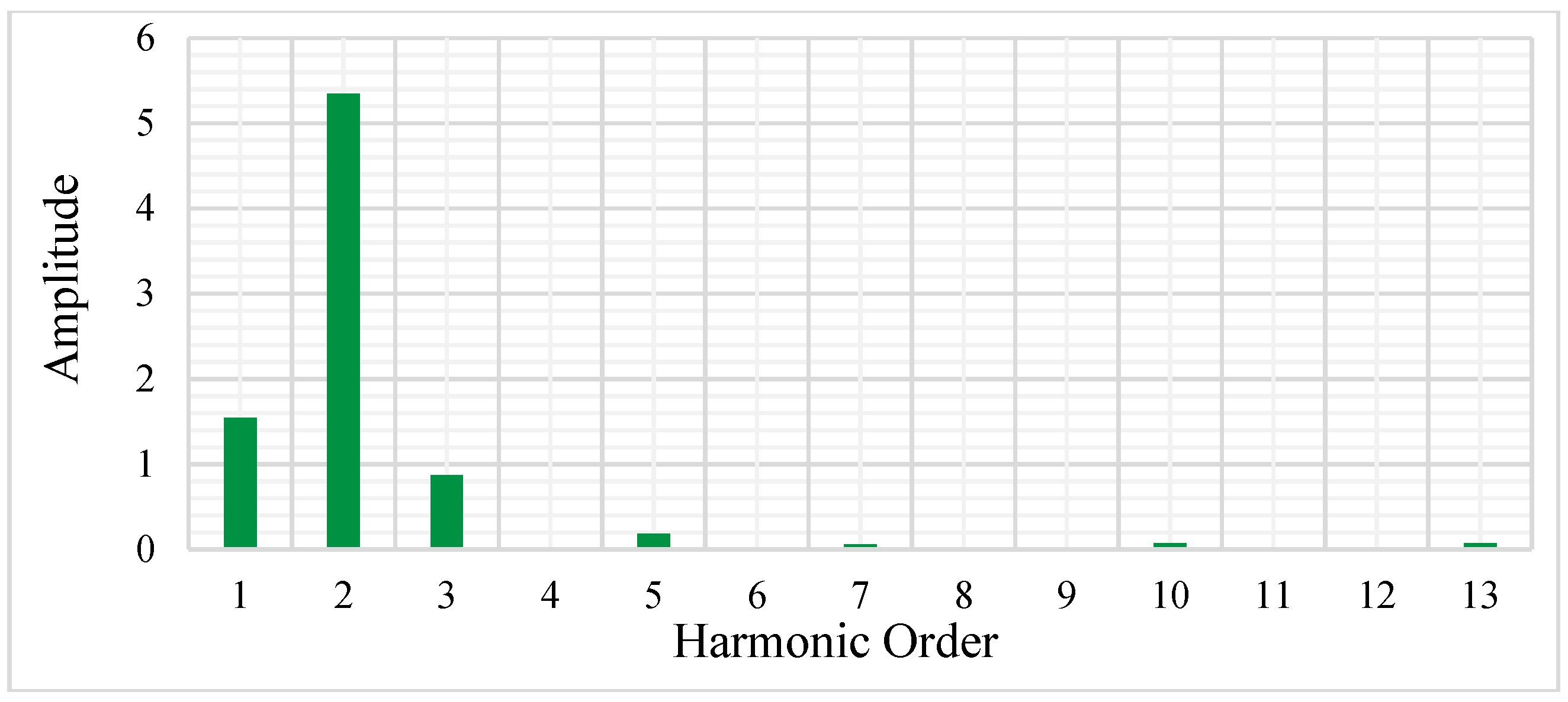
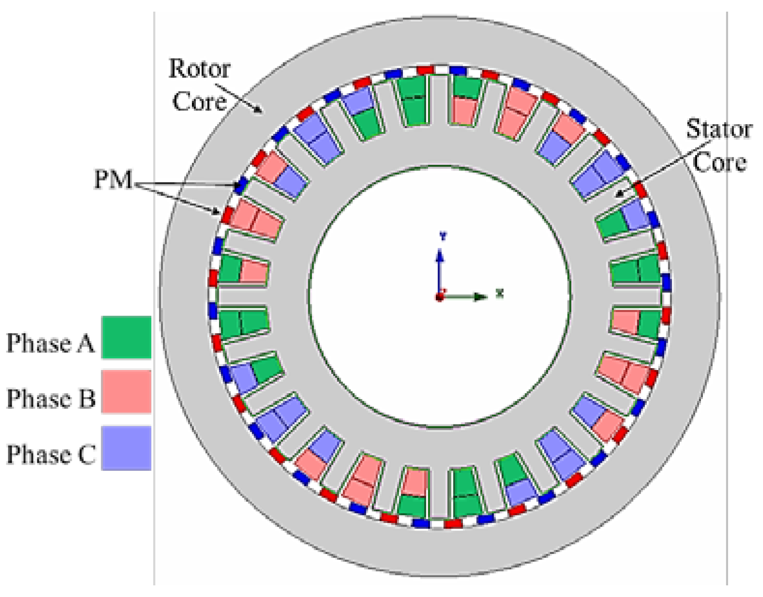
Figure 3.
Machine Layout with stator and rotor winding configuration.
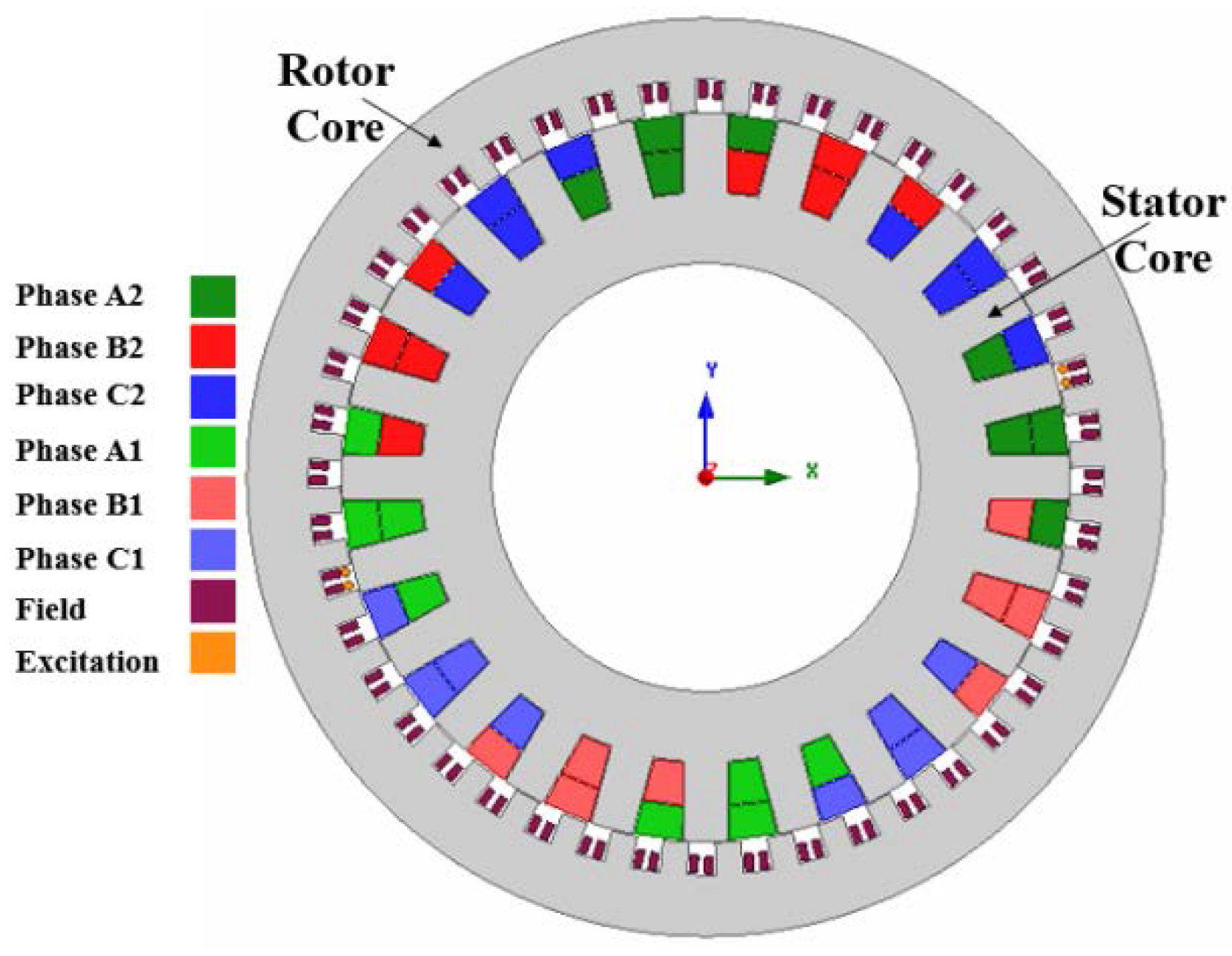
Figure 4.
(a) Air gap flux density; (b) Harmonic order of no-load flux density.

Figure 5.
(a) Induced back EMF for 5 A DC field current at 300 rpm and (b) electromagnetic torque.
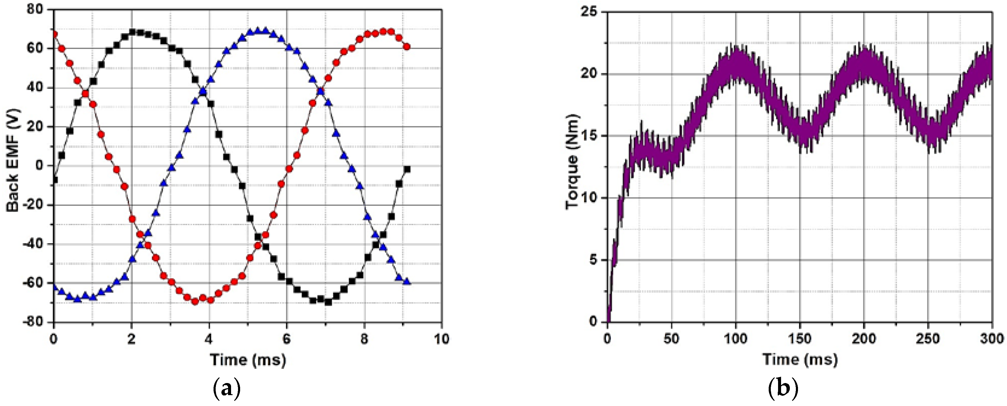
Figure 6.
(a) Flux density plot and (b) flux lines plot.

Figure 7.
Effect of variation of field winding turns on machine performance (a) torque; (b) torque ripple; (c) efficiency; and (d) power factor.
Figure 7.
Effect of variation of field winding turns on machine performance (a) torque; (b) torque ripple; (c) efficiency; and (d) power factor.
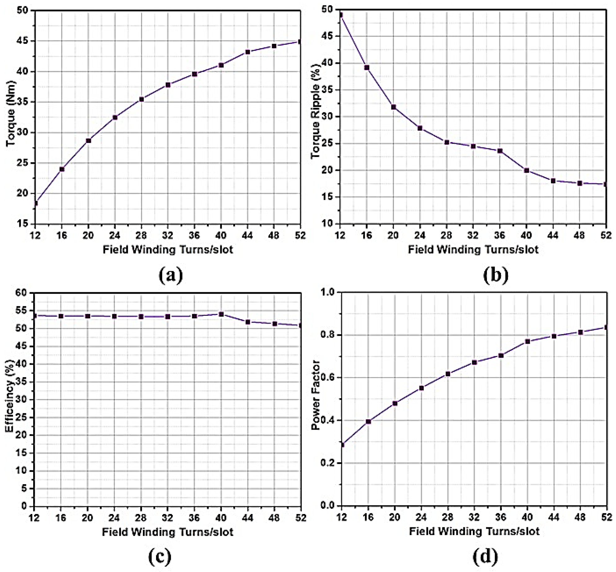
Figure 8.
Effect of variation of excitation winding turns on machine performance (a) torque; (b) torque ripple; (c) efficiency; and (d) power factor.
Figure 8.
Effect of variation of excitation winding turns on machine performance (a) torque; (b) torque ripple; (c) efficiency; and (d) power factor.
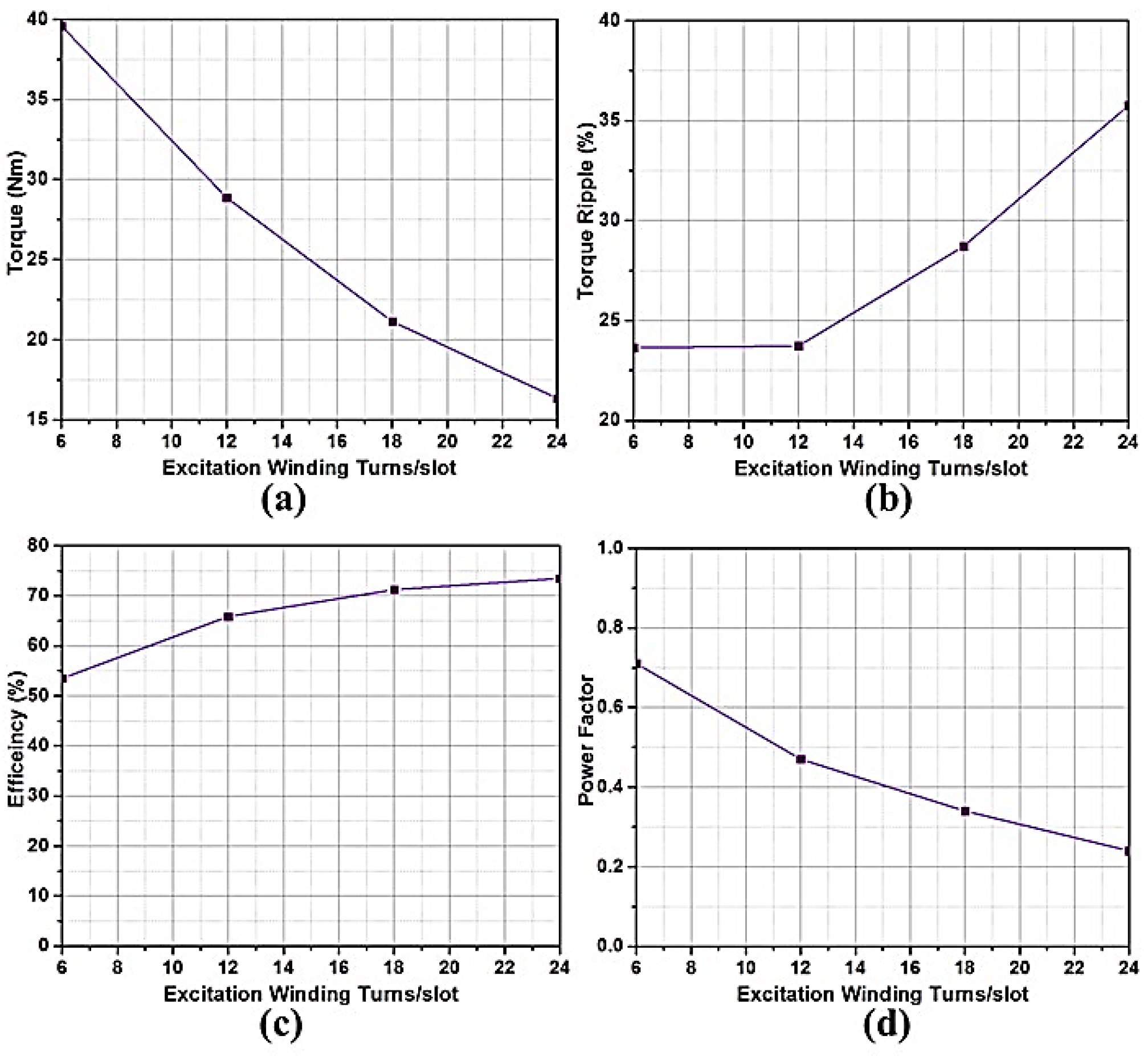
Figure 9.
Effect of variation of stator winding turns on machine performance (a) torque; (b) torque ripple; (c) efficiency; and (d) power factor.
Figure 9.
Effect of variation of stator winding turns on machine performance (a) torque; (b) torque ripple; (c) efficiency; and (d) power factor.

Figure 10.
Optimal design process.

Figure 11.
Optimal model performance (a) rotor currents and (b) electromagnetic torque.

Figure 12.
Optimal model (a) flux density plot and (b) flux lines plot.
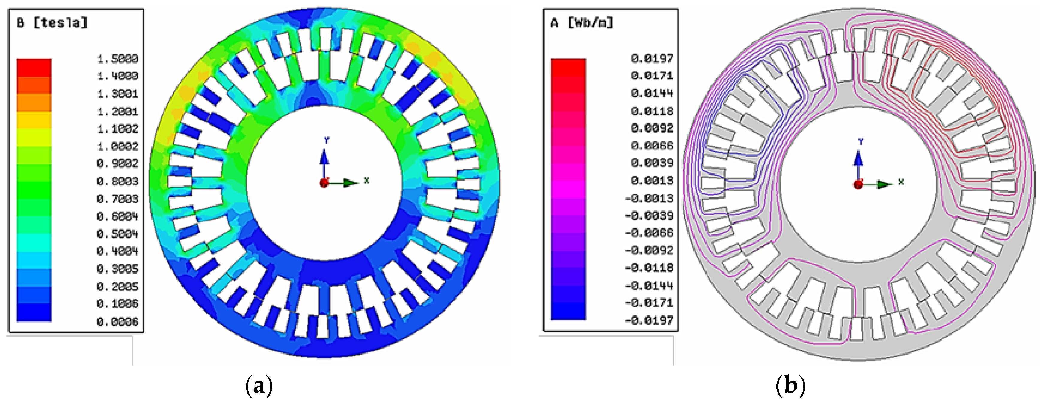
Figure 13.
Rotor field winding currents for different speeds.
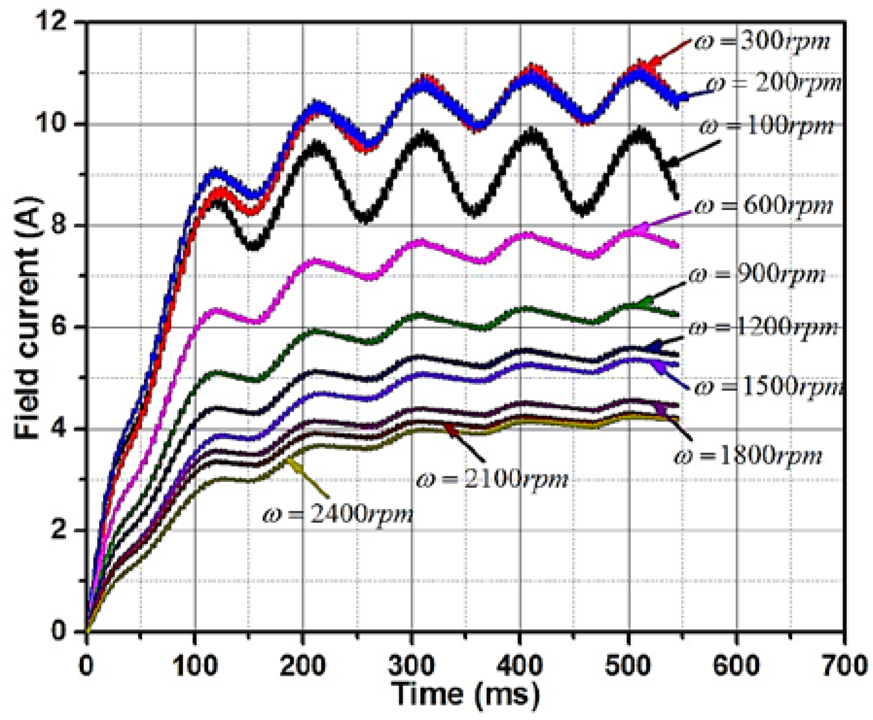
Figure 14.
2D model for equivalent permanent magnet vernier machine (PMVM).

Figure 15.
Back EMF comparison.

Figure 16.
Efficiency comparison of the BL-WRVM and PMVM.


Table 1.
Design parameters of the basic model of the brushless wound-rotor vernier machine (BL-WRVM).
Table 1.
Design parameters of the basic model of the brushless wound-rotor vernier machine (BL-WRVM).
| Parameter | Units | Vernier Machine |
|---|---|---|
| Stator Poles | - | 4 |
| Stator Slots | - | 24 |
| Rotor Field Poles | - | 44 |
| Rotor Slots | - | 44 |
| Operating speed | rpm | 300 |
| Stator outer diameter | mm | 238 |
| Stator inner diameter | mm | 140 |
| Air gap length | mm | 0.5 |
| Rotor inner diameter | mm | 239 |
| Rotor outer diameter | mm | 300 |
| Machine axial length | mm | 30 |
Table 2.
Performance of the basic model of the BL-WRVM.
| Parameter | Units | Vernier Machine (Basic Model) |
|---|---|---|
| Torque | Nm | 18.33 |
| Torque ripple | % | 49 |
| Efficiency | % | 55 |
| Power Factor | - | 0.28 |
Table 3.
Performance comparison of the basic and optimized models.
| Parameter | Units | BL-WRVM (Basic Model) | BL-WRVM (Optimized Model) | ||
|---|---|---|---|---|---|
| FEA | Algorithm | FEA | |||
| Design variable | Turns/slot | 6 | 8 | ||
| Turns/slot | 90 | 60 | |||
| Torque | - | Nm | 18.42 | 18.81 | 18.44 |
| Torque ripple | % | 49.0 | 22.34 | 23.25 | |
| Efficiency | % | 55.0 | 57.83 | 58.93 | |
| Power factor | - | 0.28 | 0.68 | 0.62 | |
Table 4.
Wide-Speed Performance of BL-WRVM.
| Parameter | 100 rpm | 200 rpm | 300 rpm | 600 rpm | 900 rpm | 1200 rpm | 1500 rpm | 1800 rpm | 2100 rpm | 2400 rpm |
|---|---|---|---|---|---|---|---|---|---|---|
| Input Current (A) | 1 | 1 | 1 | 0.67 | 0.54 | 0.46 | 0.39 | 0.37 | 0.35 | 0.31 |
| Field Current (A) | 9.09 | 10.63 | 10.56 | 7.68 | 6.05 | 5.49 | 5.26 | 4.47 | 4.23 | 4.17 |
| Torque (Nm) | 17.94 | 18.21 | 18.44 | 9.31 | 6.11 | 4.57 | 3.75 | 2.98 | 2.65 | 2.30 |
| Copper Loss (W) | 271.22 | 365.33 | 360.83 | 189.55 | 117.97 | 96.83 | 88.42 | 63.99 | 57.38 | 55.40 |
| Core Loss (W) | 11.03 | 24.6 | 43.06 | 62.67 | 78.67 | 95.16 | 118.05 | 125.47 | 146.19 | 166.43 |
| Efficiency (%) | 39.97 | 49.45 | 58.93 | 69.89 | 74.56 | 74.98 | 74.05 | 74.83 | 74.11 | 72.29 |
Table 5.
Wide-Speed Performance of PMVM.
| Parameter | 100 rpm | 200 rpm | 300 rpm | 600 rpm | 900 rpm | 1200 rpm | 1500 rpm | 1800 rpm | 2100 rpm | 2400 rpm |
|---|---|---|---|---|---|---|---|---|---|---|
| Core Loss (W) | 5.06 | 11.85 | 20.22 | 32.78 | 59.14 | 93 | 135.42 | 186.07 | 245 | 310.14 |
| Efficiency (%) | 90.69 | 93.54 | 94.29 | 92.57 | 88.92 | 84.62 | 79.17 | 74.44 | 69.42 | 64.13 |
© 2018 by the authors. Licensee MDPI, Basel, Switzerland. This article is an open access article distributed under the terms and conditions of the Creative Commons Attribution (CC BY) license (http://creativecommons.org/licenses/by/4.0/).
Share and Cite
MDPI and ACS Style
Ali, Q.; Hussain, A.; Baloch, N.; Kwon, B.I. Design and Optimization of a Brushless Wound-Rotor Vernier Machine. Energies 2018, 11, 317. https://doi.org/10.3390/en11020317
AMA Style
Ali Q, Hussain A, Baloch N, Kwon BI. Design and Optimization of a Brushless Wound-Rotor Vernier Machine. Energies. 2018; 11(2):317. https://doi.org/10.3390/en11020317
Chicago/Turabian StyleAli, Qasim, Asif Hussain, Noman Baloch, and Byung Il Kwon. 2018. "Design and Optimization of a Brushless Wound-Rotor Vernier Machine" Energies 11, no. 2: 317. https://doi.org/10.3390/en11020317
Note that from the first issue of 2016, this journal uses article numbers instead of page numbers. See further details here.