Article

Selective Harmonic Elimination in a Wide Modulation Range Using Modified Newton–Raphson and Pattern Generation Methods for a Multilevel Inverter

1
Department of Electrical Engineering, Qatar University, Doha Post Box No. 2713, Qatar
2
Department of Electrical Engineering, Aligarh Muslim University, Aligarh 202002, India
3
Department of Energy Technology, Aalborg University, 6700 Esbjerg, Denmark
*
Author to whom correspondence should be addressed.
Energies 2018, 11(2), 458; https://doi.org/10.3390/en11020458
Submission received: 19 January 2018 / Revised: 5 February 2018 / Accepted: 11 February 2018 / Published: 22 February 2018

Abstract

:
Considering the aim of having low switching losses, especially in medium-voltage and high-power converters, the pre-programmed pulse width modulation technique is very useful because the generated harmonic content can be known in advance and optimized. Among the different low switching frequency techniques, the Selective Harmonics Elimination (SHE) modulation method is most suitable because of its direct control over the harmonic spectrum. This paper proposes a method for obtaining multiple solutions for selectively eliminating specific harmonics in a wide range of modulation indices by using modified Newton–Raphson (NR) and pattern generation techniques. The different pattern generation and synthesis approach provide more degrees of freedom and a way to operate the converter in a wide range of modulation. The modified Newton–Raphson technique is not complex and ensures fast convergence on a solution. Moreover, multiple solutions are obtained by keeping a very small increase in the modulation index. In the previous methods, solutions were not obtainable at all modulation indices. In this paper, only exact solutions to the low-order harmonics elimination for Cascaded H-bridge inverter are reported for all modulation indices. Analytical and simulation results prove the robustness and correctness of the technique proposed in this paper.

1. Introduction

The performance of a VSC mostly depends on the type of PWM strategy chosen for its operation. The PWM schemes for power converters can be broadly classified as high switching frequency PWM, such as sine PWM; space vector PWM; and low switching frequency, such as Selective Harmonics Elimination (SHE), Space Vector Modulation (SVM), and selective harmonics mitigations (SHM) schemes [1,2,3,4,5,6,7,8,9,10]. The high switching frequency PWM schemes (in kHz) are used in applications where power quality is of more importance than switching losses (mainly low power applications). Whereas low switching frequency (50–800 Hz) [11,12]. PWM schemes are employed in medium-voltage, high-power voltage source converters, where switching losses arethe main constraint, along with power quality. Among the different low switching frequency techniques, SHE is a pre-programmed modulation method thatwas proposed to eliminate two lower-order harmonics by having additional switching angles in the square wave voltage waveform [13]. It was developed into a generalized meansof obtaining the desired voltage byselectively eliminating the lower-order harmonics [14]. The SHE PWM exhibits some distinct features in comparison to other PWM techniques such as: (i) low converter switching frequency, which contributes tothe reduction in switching losses and hence increases the efficiency and reliability of the converter; (ii) in SHE-PWM, unlike other PWM techniques, overmodulation is possible, which causes an increased utilization of the DC bus; (iii) selective elimination of lower-order harmonics results in high power quality and lower harmonic losses; (iv) high quality of output voltage and current also reduces the ripple in the DC link current and, therefore, a reduction in the size of the DC link filter components can be achieved.
Multilevel converters represent a very important topic in modern power electronics and many research groups are working on topologies, modulation techniques, and control algorithm strategies to improve the global behaviour of the system. In medium- and high-power applications, it is not good practice to use high switching frequencies because the thermal losses could damage the switching devices. Therefore, low switching frequency modulation techniques based on pre-computed PWM switching patterns can be very useful. The medium-voltage inverter operated with SHE normally has aquarter wave symmetrical stepped voltage waveform at output at fundamental frequency. However, several switchescan be done in one quarter of the cycle to obtain a better quality output waveform as it will eliminate harmonics but at the cost of higher switching losses. The biggest challenge in the implementation of the SHE-PWM technique is solving the set of trigonometric equations with the multiplicity of angles obtained after applying a Fourier series analysis of the output waveforms. These sets of equations are highly non-linear and transcendental in nature and may exhibit multiple solutions, a unique solution, or no solution in a different range of modulation index. The methods most commonly used to solve these equations are numerical methods, algebraic methods, and evolutionary-algorithm-based optimization methods. The numerical methods include the conventional Newton–Raphson (NR) algorithm [14] and sequential homotopy [15]. The algebraic methods introduced recently include resultant elimination theory [16,17] and Groebner bases with symmetric polynomials [18]. The evolutionary-algorithm-based optimization methods include random searching methods thatoptimize an objective function based on a genetic algorithm [19], modified species-based particle swarm optimization [20,21], the ant-colony-based algorithm [22], artificial neural network real-time angle generation [23], the colonial competitive algorithm [24], and the bee algorithm [25]. A universal method based on equal area criteria also introduced in [26] tries to solve the problem by having only four equations, irrespective of number of voltage levels. In numerical techniques, for fast and sure convergence, a good initial guess is necessary and finding multiple solutions is difficult and involves complicated calculations. Metaheuristic-based optimization methods may not converge onan exact solution of the equations but rather minimize an objective function and give an approximate solution with a particular initial guess. The solution tothis method is highly dependent on the formulation of the objective function and search space. Also, the solution depends on the parameter assumed in the algorithm and requiresexpert programming for getting reliable solutions. The limitations of numerical and metaheuristic methods can be overcome by algebraic methods thatcan provide all the solutions at a particular modulation index. However, because of the involvement of a high degree of polynomials, it is complicated and takes a lot oftime to evaluate all possible solutions.
In this paper, a pattern synthesis approach based on different voltage levels at different modulation rangesis proposed and investigated. The trigonometric transcendental equations obtained from different patterns have been solved using a modified NR method. The proposed modified NR method is not sensitive to the initial guesses as in the case of the conventional NR method. Moreover, the modified NR method is also capable of generating multiple solutions in amodulation range, which is not possible with conventional NR methods. Different patterns have been synthesized for an 11-level cascaded H-bridge; three-phase inverter and switching angles are computed in a wide range of modulation indices with multiple solutions. In the existing literature, the problem is aggravated when the modulation index is low and generally few solutions are obtained. This limitation is overcome in the proposed approach, which provides more flexibility and degrees of freedom and at least one solution forthe entire range of the modulation index.

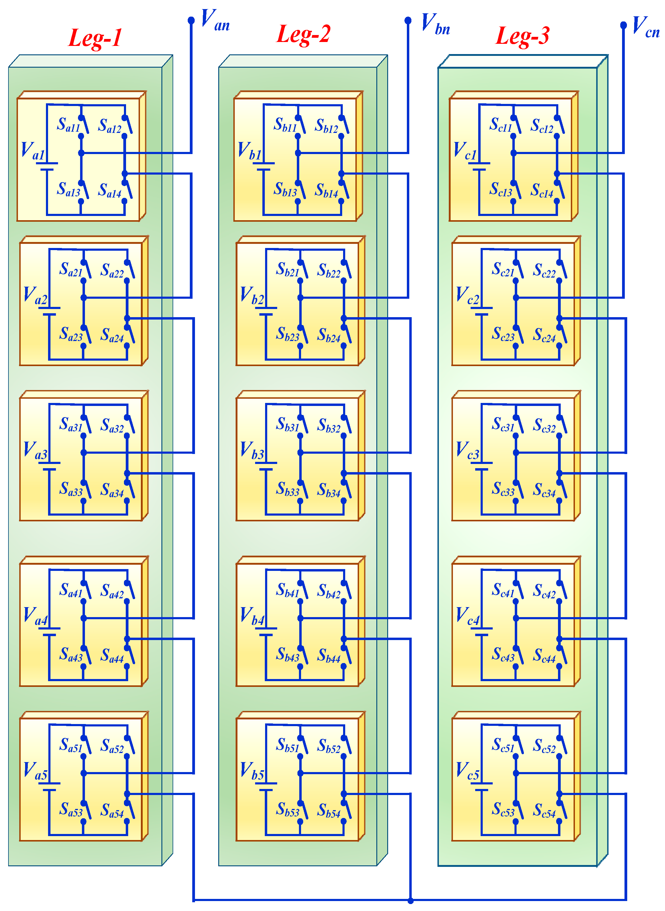
2. Eleven-Level Cascaded H-Bridge Inverter

The cascaded H-bridge multilevel inverter can have several H-bridge cells connected in cascades to obtain higher voltage and power at output with fewerrating power switches [27,28,29,30,31,32,33,34,35]. It consists of several separate DC sources to produce a stepped waveform very close to the sinusoidal voltage waveform with lesser THD. Its modular structure and circuit flexibility makes it more suitable for medium-voltage and high-power applications. Further the modulation method can be extendedfor more number of phases (>3) by simply increasing the number of legs horizontally.
In this paper a three-phase balanced system has been considered, which is mostly used in medium-voltage, high-power applications in industry. Figure 1 shows a three-phase H-bridge inverter with five separate DC sources in each leg connected in a cascade. The number of levels in the output voltage is given by 2N + 1, where N is the number of separate DC sources; since there are five separate DC sources here, it will be an 11-level inverter and its phase voltage is given by Van = (Va1 + Va2 + Va3 + Va4 + Va5). Each cell can generate three voltage levels of +Vdc, 0 and −Vdc at its terminal depending upon the switching states of power switches. The switching states and corresponding output from a cell areshown in Table 1. The main objective of the SHE-PWM technique is to obtain a desired output waveform very close to sinusoid and eliminate some undesired harmonics (usually lower-order harmonics) from the variable output voltage in a wide range of operations. In all the cell switches, SX1 (where X denotes the respective voltage source) and SX4 operate together, while SX2 and SX3 operate simultaneously but in a complementary way. To avoid direct short circuiting in the cell, some dead band is also provided, which is normally in the range of microseconds.

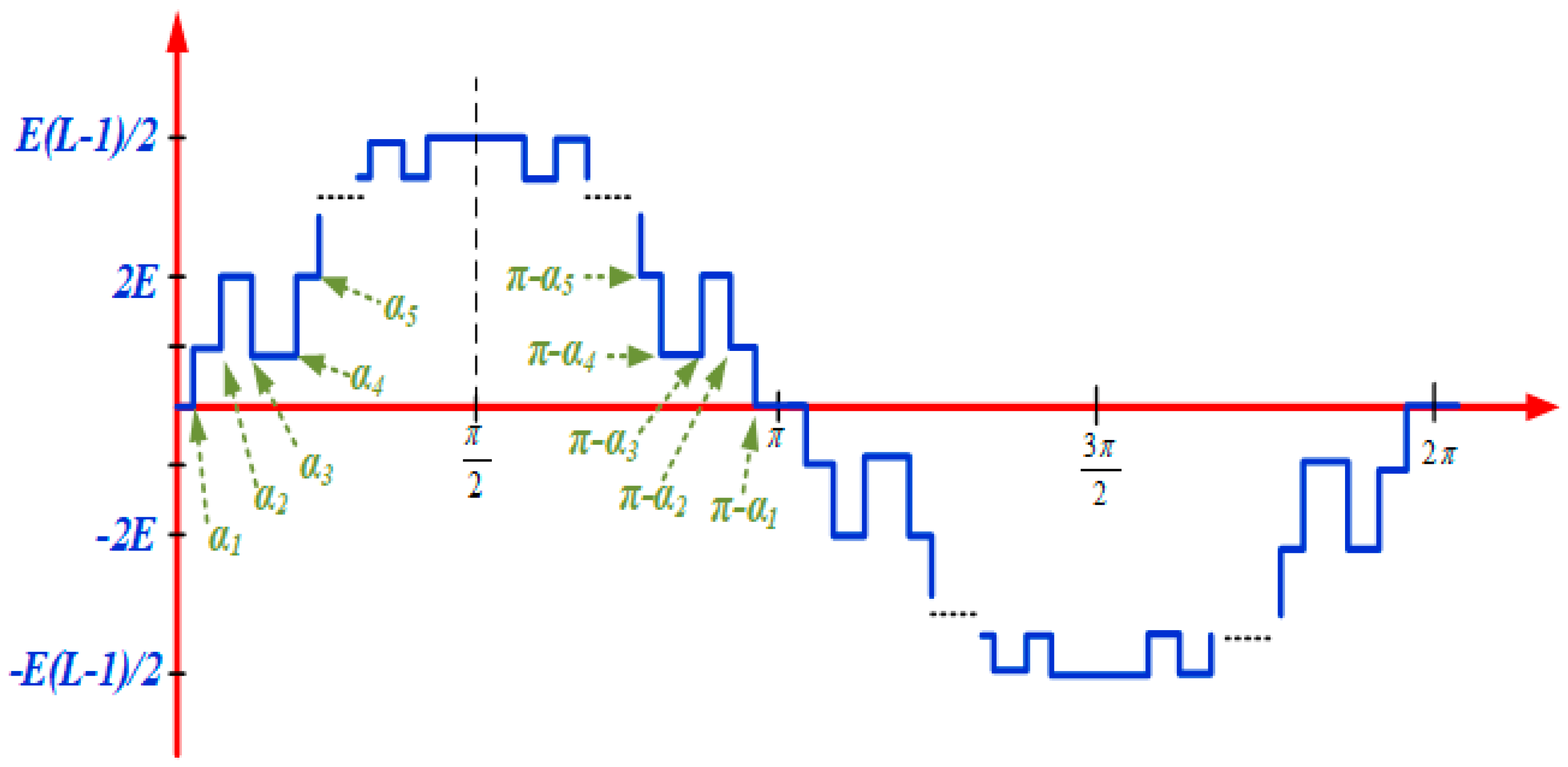
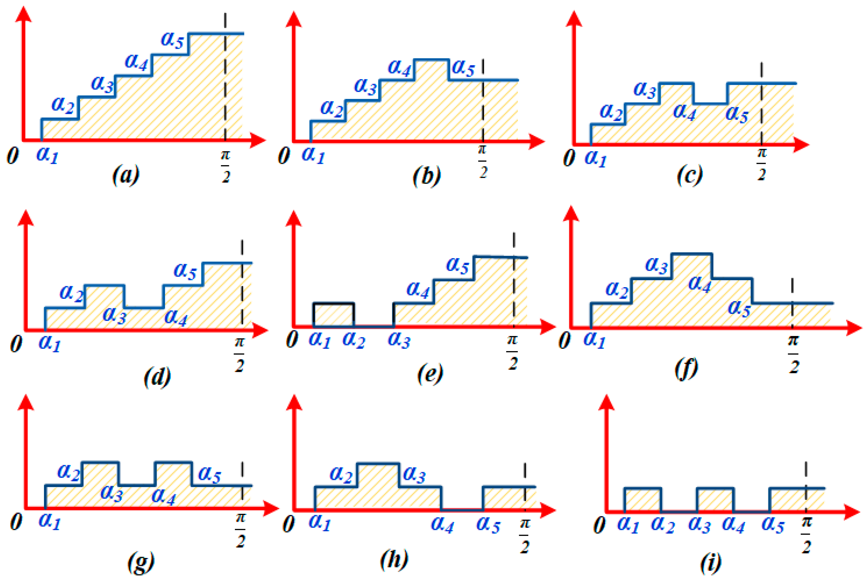
3. Problem Formulation and Mathematical Modelling

The AC output voltage of the cascaded H-bridge is given by the sum of voltages from different H-bridges connected in cascades. To analyse the output voltage waveform from the inverter, the Fourier series expansion technique is used. The general Fourier series expansion can be expressed as:
f ( t ) = a 0 + n = 1 a n cos ( n ω t ) + b n sin ( n ω t ) ,
where Fourier coefficients are given by:
a 0 = 1 T 0 T f ( t ) d t b n = 2 T 0 T f ( t ) sin ( n ω t ) d t b n = 2 T 0 T f ( t ) sin ( n ω t ) d t } .
The general L-level inverter output voltage waveform was generated inthe fundamental frequency switching scheme from the multilevel inverter by considering equal separate DC voltage. After applying the Fourier series theory to the output voltage waveform of a multilevel inverter, which has the odd quarter-wave symmetry shown in Figure 2, a0 = 0 and an = 0. Also, because of even wave symmetry, all even-numbered terms in bn coefficients will be zero. The third harmonics need not be considered for elimination because the triple harmonics automatically get cancelled in the line-to-line voltages for a balanced three-phase system and will not appear in final output waveforms. The Fourier series coefficients are obtained as in Equation (3):
b n = { 4 E n π k = 1 N cos ( n α k ) ,   for   odd   n 0 ,   for   even   n ,
where bn is the amplitude of the nth harmonics and N is the number of separate DC sources or maximum attainable level in the output waveform. Therefore, the phase to neutral output voltage can be expressed as:
V o u t = n = 1 [ 4 E n π k = 1 N cos ( n α k ) ]   sin ( n ω t ) .
In a more general form, the output voltage can be written as:
V o u t = n = 1 [ 4 E n π k = 1 N ± cos ( n α k ) ]   sin ( n ω t ) .
For the rising edge of αk, the sign will be “+” and for the falling edge of αk it will be “−”. Thus, the equation for the fundamental frequency switching control method can be expressed as:
V ( ω t ) = n = 1 , 3 , 5 4 E n π ( ± cos ( n α 1 ) ± cos ( n α 2 ) ± ± cos ( n α N ) ) sin ( n ω t ) .
Considering only rise edges, Equation (6) can be developedas follows:
k = 1 N cos α k M = 0 k = 1 N cos ( 5 α k ) = 0 k = 1 N cos ( n α k ) = 0 }
M = V 1 V 1 max = V 1 4 N E / π = m N
or the SHE equation can be formulated as
minimize   f ( α ) subject   to       g k ( α ) 0 , k = 1 , 2 , M       h t ( α ) = 0 , t = 1 , 2 , T       L i α i U i , i = 1 , 2 , N .
The feasible range of solutions in mathematical notation can be represented by
Ω = { α = [ α 1 , α 2 , α 3 , α N ] R N | g k ( α ) 0 , h t ( α ) = 0 , L i α i U i   i } .
Here the first four non-triple lower harmonics, i.e., 5th, 7th, 11th and 13th, areconsidered for elimination and the required fundamental voltage magnitude at the output is achieved. For linear operation of the converter, the modulation index M should be 0 < M < 1. For a cascaded multilevel inverter operated at fundamental frequency with five separate DC sources, a total, 25 = 32 different switching patterns are possible. Out of a total of 32 patterns, 16 are just a mirror image of thehorizontal axis and only nine patterns are useful for generating physically correct waveforms, as shown in Figure 3.

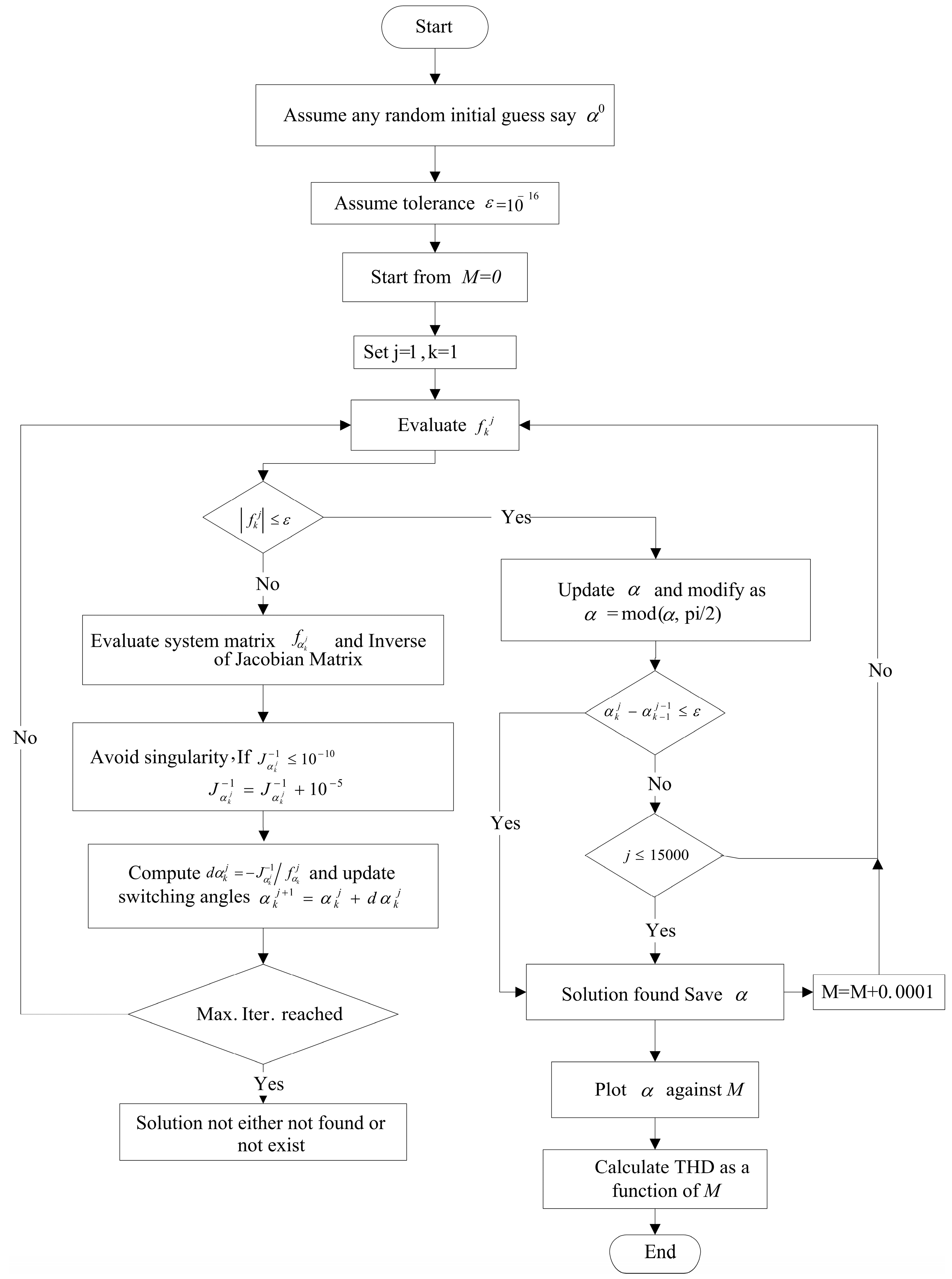
4. Modified NR Algorithm to Solve the SHE Problem

The Modified NR method begins with any random initial guess in the range 0 to (π/2) (assuming quarter wave odd symmetry in the PWM waveform) and generally converges at a zero of a given system of nonlinear equations. If there exists a solution, it usually runs for a large number of iterations. Here the algorithm is run in a discrete numbers of points, usually in very small steps of modulation index change (in this paper, modulation steps of 0.0001 areconsidered). The multiplicity of solutions in a particular range of modulation index is due to its convergence at different solution sets at different M in the neighbourhood. One can still decrease the step size to search for more solutions in some particular range of M. The flow chart is given in Figure 4.
This isexecuted repetitively in the complete range of the modulation index, i.e., from 0 to 1, to find multiple solutions for PWM with guaranteed convergence. The algorithm ensures all possible solutionsare generated, starting with a random initial guess. The THD for all solutions has been calculated at different modulation index using Equation (9); here harmonics of the order upto 200 are considered for the calculations:
% THD = [ n = 5 , 7 , 11 , 13 , 200 ( V n V 1 ) 2 ] × 100 .
Mathematical equations for PWM output waveforms have been developed. The modified NR method discussed in Section 4 is applied to evaluate the switching instants for the bidirectional power switches. The technique presented in this work was first tested on the well-known results available in the literature—for instance, the five-angle case for a three-phase system eliminating non-triple, low-order harmonics—and the results obtained arecompared. Some new switching angles were found by this method. For instance, at M = 0.55, for all rising edge cases, there were three sets of switching angles {34.46, 44.57, 54.24, 65.40, 78.04}, {19.75, 39.10, 56.52, 63.57, 88.20}, and {4.05, 37.30, 41.98, 79.31, 88.63}, for α1, α2, α3, α4, and α5. The third set obtained here is novel and may havebetter performance than the first two sets; in addition, it provides higher redundancy. It clearly reflects the robustness of the technique.
The selective solutions for the entire pattern shown in Figure 3 have been evaluated using the modified NR method and the results are shown for the different patterns in Figure 5. The switching instants for a particular pattern are obtained at output in the modulation range of 0 to 1 (in steps of 0.0001).
The total harmonics distortion, as a function of the modulation index for the entire pattern, is shown in Figure 6. It clearly shows that there is a wide variation in %THD for different solution sets and patterns. The result for switching angles shows multiple solutions, unique solutions, and no solution in different modulation ranges. When all the patterns are grouped together, a lot of solutions are available to operate the converter, even at a very low modulation index. Selecting a particular option from anumber of solutions is normally application-dependent. One can select a particular solution simply based on the lower THD obtained or by takinginto account the next low-order non-eliminated harmonics. Other criteria could be based on the minimum switching transition in order to further reduce the power losses in the switches. Based on optimal THD criteria, the optimum switching angles in different ranges of M for all possible patterns of Figure 3 have been given in Figure 6. The switching angles for the range of modulation index of the entire pattern aregiven and compared in Figure 7. It is evident that there are several options available to operate the inverter in different modulation ranges to obtain the desired performance. From the computational results, it is clear that at a higher modulation value the THD is better than at lower modulation. At a lower modulation range, one can utilize a high switchingfrequency technique like space vector PWM by operating power switches with hybrid PWM, which could be an active research area. The maximum error in the harmonics function evaluation and the harmonics profile for pattern ‘a’ are shown in Figure 8. It is evident from the figure that an accurate solution tothe SHE equation is obtained and the targeted harmonics are completely eliminated from the output waveform. This is one of the major advantages of utilizing the modified Newton Raphson technique tosolve SHE equations.
To validate the computational results for switching angles, a simulation is carried out in MATLAB/SIMULINK software tool R2017a (9.2.0.538062) for an 11-level, three-phase cascaded H-bridge inverter. The DC source for each H-bridge unit is considered 100 V. The simulation results cover the whole range of M for the entire pattern. Selected simulation resultsarepresented in Figure 9. The simulation results for phase voltage at modulation index, M = 0.6, are shown in Figure 9a, where all the H-bridge cells are producing +100 V at the output. In this case, in a quarter of a full output cycle, the SX1 and SX3 switches of the first, second, third, fourth, and fifth cells of the first leg are turned on at instant α1 = 26.65°, α2 = 43.95°, α3 = 51.56°, α4 = 62.43° and α5 = 72.54°, respectively, or at time instants of 1.48 ms, 2.44 ms, 2.86 ms, 3.46 ms, and 4.03 ms, respectively. Similarly, the switches SX2 and SX3 of the first, second, third, fourth, and fifth cells are turned ON at instant α1 = 206°, α2 = 223.95°, α3 = 231.56°, α4 = 242.43°, and α5 = 252.54°, respectively, or at time instants 11.48 ms, 12.44 ms, 12.86 ms, 13.46 ms, and 14.03 ms. The switches remain turned ON for a duration of 35.19%, 25.58%, 21.35%, 15.32%, and 9.70% of a full cycle, respectively. The simulation results obtained following asimilar procedure arein close agreement withthe analytical results. Hence it confirms the robustness and correctness of the technique adopted. It can be seen that the low order non-triple harmonics such as 5th, 7th, 11th, and 13th are eliminated from the line-to-line output voltage and the THD is very close to the calculated value.

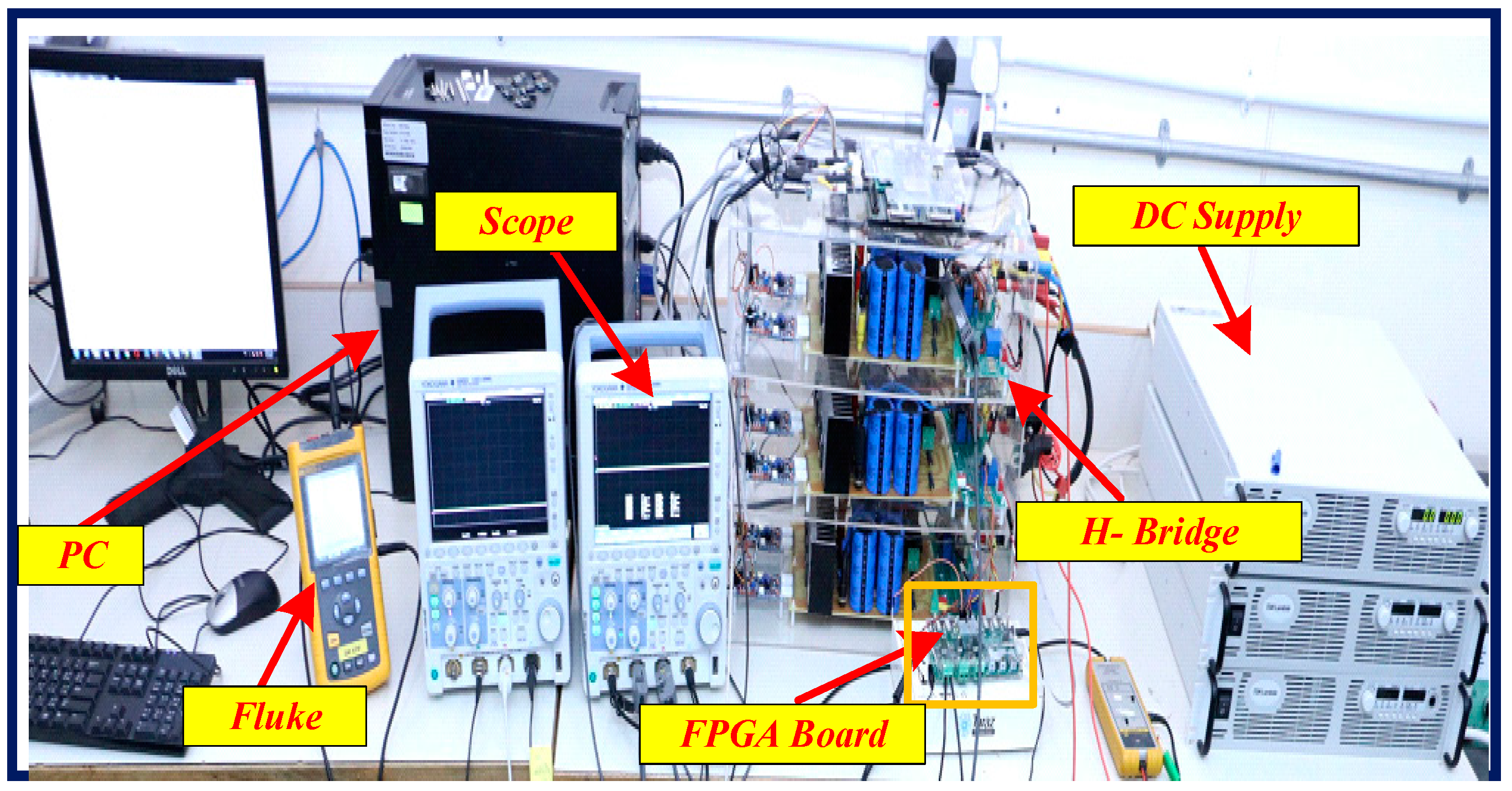
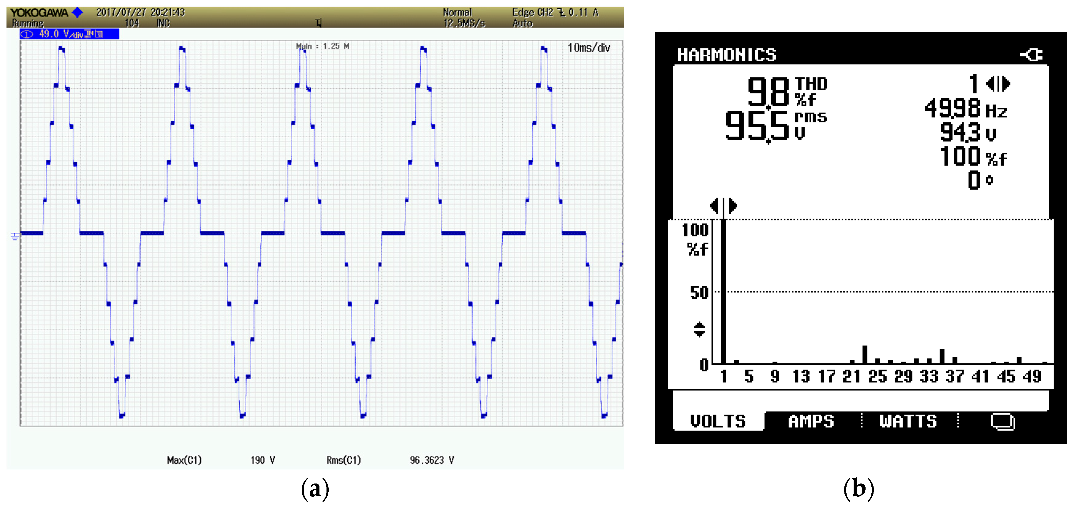
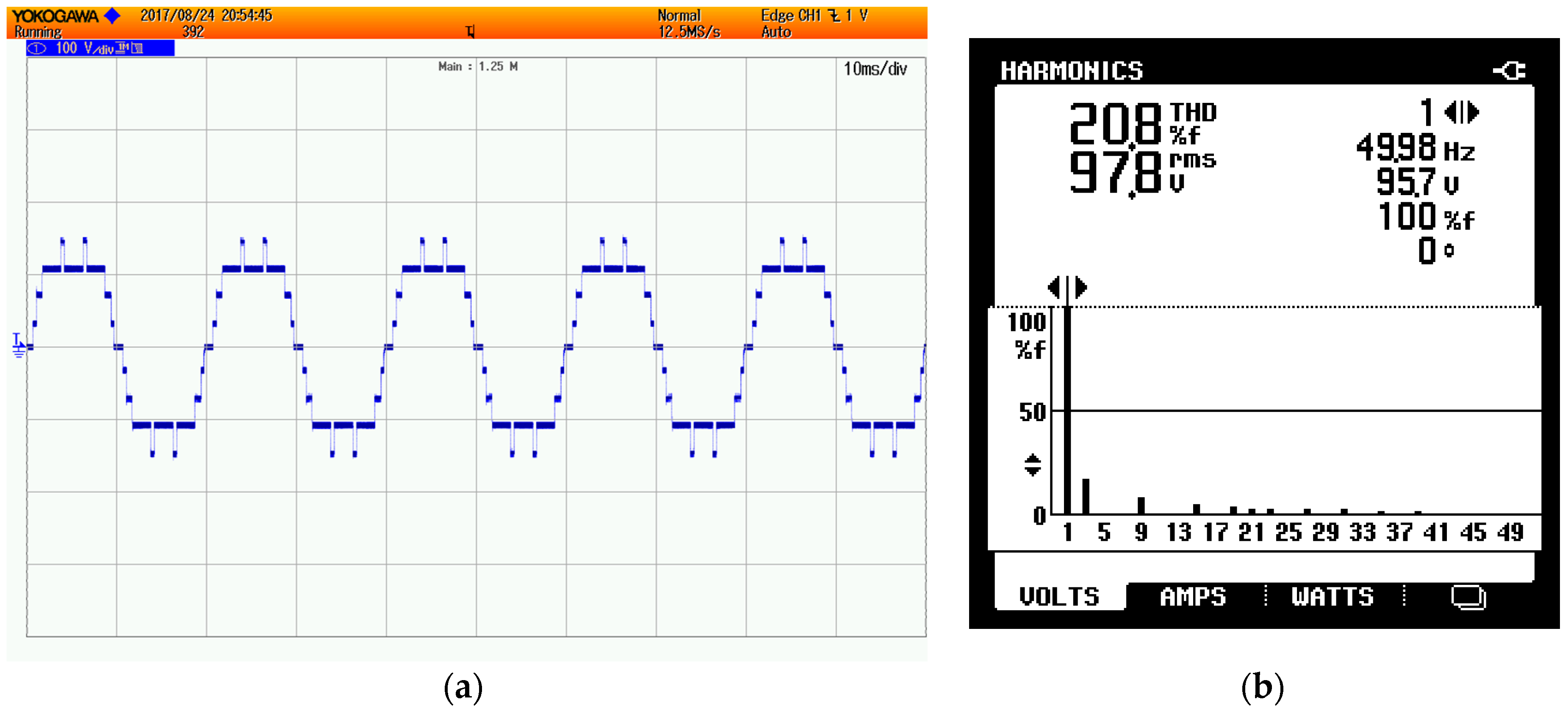
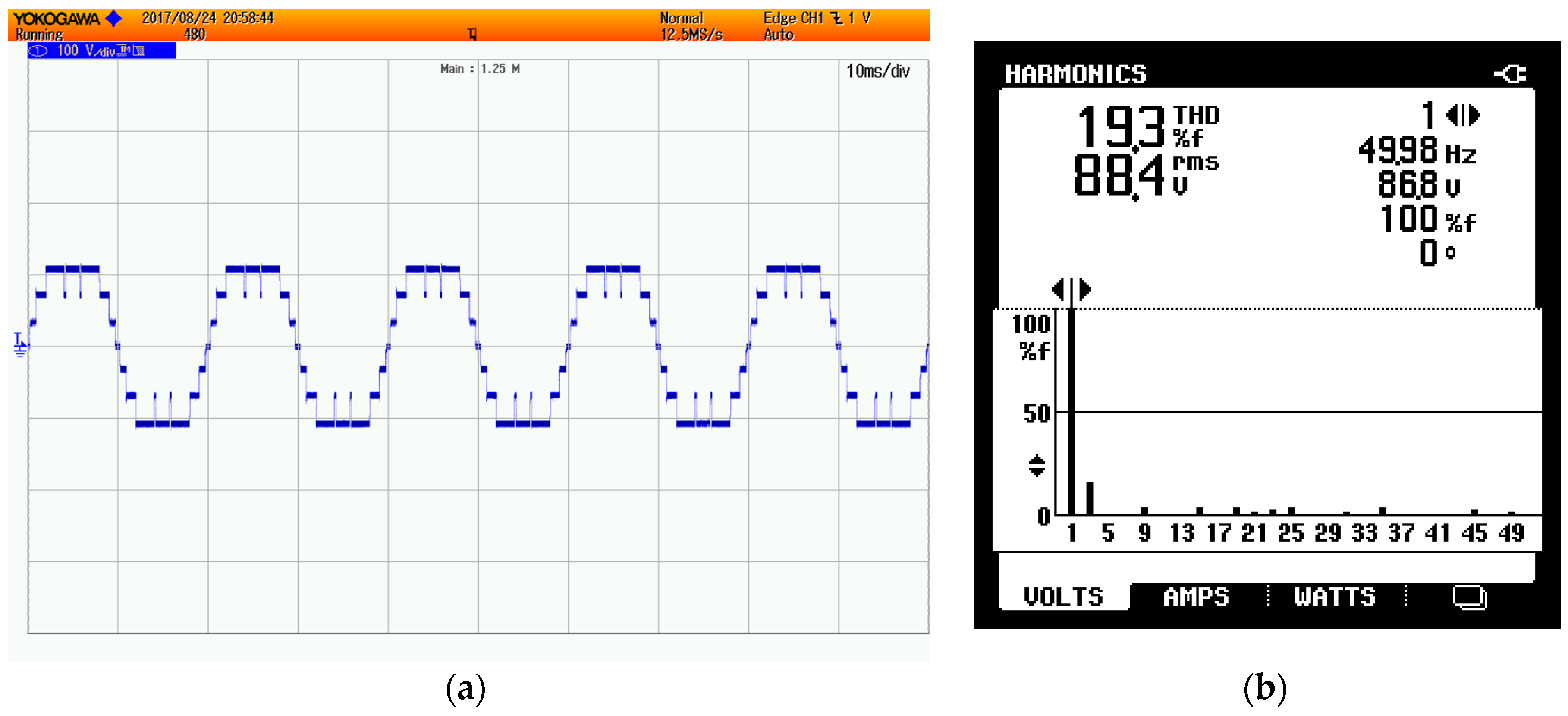
5. Hardware Setup and Experimental Results

The computational result is validated by a prototype developed in the laboratory. The switches of H-bridge inverter are bidirectional insulated gate bipolar transistors (IGBT) selected from Semikron SKM100GB12T4. The control code for harmonics elimination is built using Xilinx’s field-programmable gate array FPGA from VIRTEX-5 XC5VLX50T (Xilinx, San Jose, CA, USA). A harmonics spectrum analyser is also used in conjunction withthe scope for FFT analysis. The complete hardware setup is shown in Figure 10. The switching pulses from FPGA were given to high-speed IGBT gate drivers, which in turn supply a conditioned and proper signal to the IGBT switches.
The DC voltage for each cascaded H-bridge has been kept at 35 V. The first experiment has been carried out for pattern ‘a’ at modulation index M = 0.432 for corresponding switching angles of α 1 = 0.622 , α 2 = 0.833 , α 3 = 1.049 , α 4 = 1.313 , and α 5 = 1.561 . Figure 11 shows the output waveform and harmonics spectrum. The time axis is divided into10 ms/div, while the vertical axis is 49 V/div. The fft spectrum shown confirms that the targeted harmonics for elimination are completely eliminated from the output waveform.
Similarly, the hardware results for ‘b’ and ‘g’ are shown in Figure 12 and Figure 13, respectively. The FFT spectrum of these waveforms also shows that the targeted non-triple harmonics (5th, 7th, 11th, and 13th order) considered for elimination are completely absent. In asimilar fashion, experimental results can be obtained for the entire modulation range of different possible structures.
A LUT flip flop pair for this architecture represents one LUT paired with one flip flop within a slice. A control set is a unique combination of clock, reset, set, and enable signals for a registered element. The Figure 14 shows the design summary report for case “a”, which contains device utilization information.

6. Conclusions

In this paper, two different approaches have been proposed for obtaining multiple sets of solutions in a wide range of modulation indices. The modified NR approach ensures all possible solutions at a particular modulation index, whereas the pattern synthesizing approach ensures coverage of almost the whole range for modulation indices. Selected lower-order non-triple odd harmonics are considered for elimination from the output voltage. The multiple sets of solutions have been found in different ranges of the modulation index;whichset areoptimal is application-dependent. For instance, one can choose asolution based on optimum THD or one can select asolution based on minimum transition of power switches. From the results it is confirmed that at higher modulation indices the THD is low; however, at very low modulation indices the THD is very high, so further research can be done for hybrid PWM. However, insome modulation ranges (or in overmodulation), no solution was found. Selected simulation results are presented in this paper to confirm the validity of the theoretical and computational results.

Acknowledgments

This (publication, report, etc.) was made possible by NPRP grant # [X-033-2-007] from the Qatar National Research Fund (a member of Qatar Foundation).

Author Contributions

All authors contributed equally to the proposed research work in its final version to be decimation as full article.

Conflicts of Interest

The authors declare no conflict of interest.

References

  1. Wu, A.B. High-Power Converters and AC Drives; Wiley-IEEE Press: Hoboken, NJ, USA, 2006. [Google Scholar]
  2. Bharatiraja, C.; Babu, S.; Krishnakumar, V.; Munda, J.L.; Sanjeevikumar, P. Investigation of Slim type BLDC motor Drive with torque ripple minimization using Abridged Space-Vector PWM Control Method. Int. J. Power Electron. Drive Syst. 2017, 8, 593–600. [Google Scholar] [CrossRef]
  3. Bharatiraja, C.; Harish, S.; Munda, J.L.; Sanjeevikumar, P.; Kumar, M.S.; Bhati, V. A PWM Strategies for Diode Assisted NPC-MLI to Obtain Maximum Voltage Gain for EV Application. Int. J. Power Electron. Drive Syst. 2017, 8, 767–774. [Google Scholar] [CrossRef]
  4. Sanjeevikumar, P.; Grandi, G.; Ojo, J.O.; Blaabjerg, F. Direct Vector Controlled Six-Phase Asymmetrical Induction Motor with Power Balanced Space Vector PWM Multilevel Operation. Int. J. Power Energy Convers. 2016, 7, 57–83. [Google Scholar] [CrossRef]
  5. Subramaniam, U.; Arun Shankar, V.K.; Sanjeevikumar, P.; Kandanuru, H. Common Mode Voltage Regulation of Three Phase Three Level Neutral Point Clamped Inverter using SVPWM Technique. In Advances in Power Systems and Energy Management; Lecture Notes in Electrical Engineering; Springer Journal Publications: Singapore, 2018; Volume 436, pp. 367–376. [Google Scholar]
  6. Sanjeevikumar, P.; Blaabjerg, F.; Wheeler, P.; Fedák, V.; Duran, M.J.; Siano, P. A Novel Five-level Optimized Carrier Multilevel PWM Quad-Inverter Six-Phase Asymmetrical AC Drive. In Proceedings of the 2016 IEEE International Power Electronics and Motion Control Conference (PEMC), Varna, Bulgaria, 25–28 September 2016. [Google Scholar]
  7. Padmanaban, S.; Siano, P.; Ertas, A.H.; Selvamuthukumaran, R.; Maroti, P.K. Single-Phase Seven-Level Stack Multicell Converter Using Level Shifting SPWM Technique. In Proceedings of the 2016 IEEE 16th International Conference on Environment and Electrical Engineering (EEEIC), Florence, Italy, 7–10 June 2016. [Google Scholar]
  8. Pandav, K.M.; Mahajan, S.B.; Sanjeevikumar, P.; Badave, S.M.; Pachagade, R.M. 2.4 kW Three Phase Inverter for Aircraft Application- Hardware Implementation. In Advances in Power Systems and Energy Management; Lecture Notes in Electrical Engineering Book; Springer: Singapore, 2016. [Google Scholar]
  9. Padmanaban, S.; Blaabjerg, F.; Wheeler, P.W.; Ojo, J.O.; Maroti, P.K. A Novel Double Quad-Inverter Configuration for Multilevel Twelve-Phase Open-Winding Converter. In Proceedings of the 2016 IEEE 6th International Conference onPower Systems (ICPS), Delhi, India, 4–6 March 2016. [Google Scholar]
  10. Padmanaban, S.K.; Bhaskar, M.S.; Maroti, P.K.; Blaabjerg, F.; Siano, P.; Oleschuk, V. Hexuple-Inverter Configuration for Multilevel Nine-Phase Symmetrical Open-Winding Converter. In Proceedings of the IEEE International Conference on Power Electronics, Intelligent Control and Energy Systems (ICPEICES), Delhi, India, 4–6 July 2016. [Google Scholar]
  11. Abu-Rub, H.; Iqbal, A.; Guzinski, J. High Performance Control of AC Drives with Matlab/Simulink Models; John Wiley and Sons: Hoboken, NJ, USA, 2012. [Google Scholar]
  12. Hosseyni, A.; Trabelsi, R.; Iqbal, A.; Padmanaban, S.; Mimouni, M.F. An Improved Sensorless Sliding Mode Control/Adaptive Observer of a Five-Phase Permanent Magnet Synchronous Motor Drive. Int. J. Adv. Manuf. Technol. 2017, 93, 1029–1039. [Google Scholar] [CrossRef]
  13. Dahidah, M.S.; Konstantinou, G.; Agelidis, V.G. A Review of Multilevel Selective Harmonic Elimination PWM: Formulations, Solving Algorithms, Implementation and Applications. IEEE Trans. Power Electron. 2015, 30, 4091–4106. [Google Scholar] [CrossRef]
  14. Wei, Q.; Wu, B.; Xu, D.; Zargari, N.R. A Natural-Sampling-Based SVM Scheme for Current Source Converter with Superior Low-Order Harmonics Performance. IEEE Trans. Power Electron. 2016, 31, 6144–6154. [Google Scholar] [CrossRef]
  15. Feng, Z.; Guangzhen, Z.; Xuhui, W.; Li, Z. A novel implementation of harmonic elimination pulse width modulation technique. In Proceedings of the 2014 IEEE Conference and Expo Transportation Electrification Asia-Pacific (ITEC Asia-Pacific), Beijing, China, 31 August–3 September 2014. [Google Scholar]
  16. Chiasson, J.N.; Tolbert, L.M.; McKenzie, K.J.; Du, Z. A new approach to solving the harmonic elimination equations for a multilevel converter. In Proceedings of the 38th IAS Annual Meeting on Conference Record of the Industry Applications Conference, Salt Lake City, UT, USA, 12–16 October 2003; pp. 640–647. [Google Scholar]
  17. Yang, K.; Chen, L.; Zhang, J.; Hao, J.; Yu, W. Parallel resultant elimination algorithm to solve the selective harmonic elimination problem. IET Power Electron. 2016, 9, 71–80. [Google Scholar] [CrossRef]
  18. Yang, K.; Zhang, Q.; Yuan, R.; Yu, W.; Yuan, J.; Wang, J. Selective Harmonic Elimination with Groebner Bases and Symmetric Polynomials. IEEE Trans. Power Electron. 2016, 31, 2742–2752. [Google Scholar] [CrossRef]
  19. Ozpineci, B.; Tolbert, L.M.; Chiasson, J.N. Harmonic Optimization of Multilevel Converters Using Genetic Algorithms. IEEE Power Electron. Lett. 2005, 3, 92–95. [Google Scholar] [CrossRef]
  20. TarafdarHagh, M.; Taghizadeh, H.; Razi, K. Harmonic minimization in multilevel inverters using modified species-based particle swarm optimization. IEEE Trans. Power Electron. 2009, 24, 2259–2267. [Google Scholar]
  21. Taghizadeh, H.; Hagh, M.T. Harmonic Elimination of Cascade Multilevel Inverters with Nonequal DC Sources Using Particle Swarm Optimization. IEEE Trans. Ind. Electron. 2010, 57, 3678–3684. [Google Scholar] [CrossRef]
  22. Sundareswaran, S.; Jayant, K.; Shanavas, T.N. Inverter Harmonic Elimination through a Colony of Continuously Exploring Ants. IEEE Trans. Ind. Electron. 2007, 54, 2558–2565. [Google Scholar] [CrossRef]
  23. Filho, F.; Tolbert, L.M.; Cao, Y.; Ozpineci, B. Real-time selective harmonic minimization for multilevel inverters connected to solar panels using artificial neural network angle generation. IEEE Trans. Ind. Appl. 2011, 47, 2117–2124. [Google Scholar] [CrossRef]
  24. Etesami, M.H.; Farokhnia, N.; Fathi, S.H. Toward Harmonic Minimization in Multilevel Inverters. IEEE Trans. Ind. Inform. 2015, 11, 459–466. [Google Scholar]
  25. Kavousi, A.; Vahidi, B.; Salehi, R.; Bakhshizadeh, M.K.; Farokhnia, N.; Fathi, S.H. Application of the Bee Algorithm for Selective Harmonic Elimination Strategy in Multilevel Inverters. IEEE Trans. Power Electron. 2012, 27, 1689–1696. [Google Scholar] [CrossRef]
  26. Wang, J.; Ahmadi, D. A precise and practical harmonic elimination method for multilevel inverters. IEEE Trans. Ind. Appl. 2010, 46, 857–865. [Google Scholar] [CrossRef]
  27. Dahidah, M.S.; Agelidis, V.G. Selective Harmonic Elimination PWM Control for Cascaded Multilevel Voltage Source Converters: A Generalized Formula. IEEE Trans. Power Electron. 2008, 23, 1620–1630. [Google Scholar] [CrossRef]
  28. Napoles, J.; Leon, J.I.; Franquelo, L.G.; Portillo, R.; Aguirre, M.A. Selective harmonic mitigation technique for multilevel cascaded H-bridge converters. In Proceedings of the 2009 35th Annual Conference of IEEE Industrial Electronics, Porto, Portugal, 3–5 November 2009; pp. 806–811. [Google Scholar]
  29. Zhao, H.; Jin, T.; Wang, S.; Sun, L. A Real-Time Selective Harmonic Elimination Based on a Transient-Free Inner Closed-Loop Control for Cascaded Multilevel Inverters. IEEE Trans. Power Electron. 2016, 31, 1000–1014. [Google Scholar] [CrossRef]
  30. Aleenejad, M.; Mahmoudi, H.; Moamaei, P.; Ahmadi, R. A new fault-tolerant strategy based on a modified selective harmonic technique for three-phase multilevel converters with a single faulty cell. IEEE Trans. Power Electron. 2016, 31, 3141–3150. [Google Scholar] [CrossRef]
  31. Banaei, M.R.; Shayan, P.A. Solution for selective harmonic optimisation in diode-clamped inverters using radial basis function neural networks. IET Power Electron. 2014, 7, 1797–1804. [Google Scholar] [CrossRef]
  32. Massrur, H.R.; Niknam, T.; Mardaneh, M. Harmonic Elimination in Multilevel Inverters under Unbalanced Voltages and Switching Deviation Using a New Stochastic Strategy. IEEE Trans. Ind. Inform. 2016, 12, 716–725. [Google Scholar] [CrossRef]
  33. Grandi, G.; Sanjeevikumar, P.; Ostojic, D.; Rossi, C. Quad-inverter configuration for multi-phase multi-level ac motor drives. In Proceedings of the 2010 IEEE Region 8 International Conference on Computational Technologies in Electrical and Electronics Engineering (SIBIRCON), Irkutsk Listvyanka, Russia, 11–15 July 2010; pp. 631–638. [Google Scholar]
  34. Grandi, G.; Tani, A.; Sanjeevikumar, P.; Ostojic, D. Multi-phase multi-level ac motor drive based on four three-phase two-level inverters. In Proceedings of the 2010 International Symposium on Power Electronics Electrical Drives Automation and Motion (SPEEDAM), Pisa, Italy, 14–16 June 2010; pp. 1768–1775. [Google Scholar]
  35. Rasool, A.; Ozsoy, E.E.; Ahmad, F.; Sabanoviç, A.; Padmanaban, S. Disturbance-Observer Based Control of Voltage-Source-Converter under Unbalanced Voltage Conditions. World J. Eng. 2017, 14, 522–553. [Google Scholar] [CrossRef]
Figure 1. Eleven-level, three-phase cascaded H-bridge inverter.
Energies 11 00458 g001
Figure 2. Generalized quarter wave symmetrical L-level output voltage waveform.
Energies 11 00458 g002
Figure 3. Differentpattern synthesis switching transitions from the 11-level cascaded H-bridge inverter. (a) α 1 , α 2 , α 3 , α 4 , α 5 ; (b) α 1 , α 2 , α 3 , α 4 , α 5 ; (c) α 1 , α 2 , α 3 , α 4 , α 5 ; (d) α 1 , α 2 , α 3 , α 4 , α 5 ; (e) α 1 , α 2 , α 3 , α 4 , α 5 ; (f) α 1 , α 2 , α 3 , α 4 , α 5 ; (g) α 1 , α 2 , α 3 , α 4 , α 5 ; (h) α 1 , α 2 , α 3 , α 4 , α 5 ; (i) α 1 , α 2 , α 3 , α 4 , α 5 .
Energies 11 00458 g003
Figure 4. Flow chart of modified NR for solving SHE problem.
Energies 11 00458 g004
Figure 5. Switching angles (in radians) as function of modulation M for various switching transition (a) α 1 , α 2 , α 3 , α 4 , α 5 ; (b) α 1 , α 2 , α 3 , α 4 , α 5 ; (c) α 1 , α 2 , α 3 , α 4 , α 5 ; (d) α 1 , α 2 , α 3 , α 4 , α 5 ; (e) α 1 , α 2 , α 3 , α 4 , α 5 ; (f) α 1 , α 2 , α 3 , α 4 , α 5 ; (g) α 1 , α 2 , α 3 , α 4 , α 5 ; (h) α 1 , α 2 , α 3 , α 4 , α 5 ; (i) α 1 , α 2 , α 3 , α 4 , α 5 .
Energies 11 00458 g005
Figure 6. % Line THD for the entire pattern as a function of modulation index M.
Energies 11 00458 g006
Figure 7. Switching angle as a function of m for all the patterns.
Energies 11 00458 g007
Figure 8. (a) Maximum error in the function for pattern “a”; (b) harmonics profile at M = 0.845.
Energies 11 00458 g008
Figure 9. Simulation result for pattern ‘a’ at M = 0.6000 (a) Phase voltage; (b) line voltage; (c) harmonics spectrum.
Energies 11 00458 g009
Figure 10. Experimental setup.
Energies 11 00458 g010
Figure 11. Experimental results for pattern ‘a’ (a) output voltage waveform at M = 0.432; (b) FFT spectrum.
Energies 11 00458 g011
Figure 12. Experimental results of output voltage and THD of pattern of Figure 3b in (a,b) respectively.
Energies 11 00458 g012
Figure 13. Experimental results of output voltage and THD of pattern of Figure 3c in (a,b) respectively.
Energies 11 00458 g013
Figure 14. Summary report presenting FPGA devices’ utilization.
Energies 11 00458 g014
Table 1. Switching angles in different quadrants.
CaseSwitches’ StatesCell Output Voltage
i. ( 1 , 3 ) 0   and   ( 2 , 4 ) 0 0
ii. ( 1 , 3 ) 0   and   ( 2 , 4 ) 1 V dc
iii. ( 1 , 3 ) 1   and   ( 2 , 4 ) 0 + V dc
iv. ( 1 , 3 ) 1   and   ( 2 , 4 ) 1 0

