Reduction of Electricity Prices Using the Train to Grid (T2G) System in Urban Railway

1
Korea Testing Laboratory, Seoul 100744, Korea
2
Korea Railroad Research Institute, Uiwang 160161, Korea
3
College of Information and Communication Engineering, Sungkyunkwan University; Seoul 100744, Korea
*
Author to whom correspondence should be addressed.
†
The research reported in this study was conducted while Hyo-Sang Go was affiliated with Korea Railroad Research Institute.
Energies 2018, 11(3), 501; https://doi.org/10.3390/en11030501
Submission received: 8 December 2017
/
Revised: 19 January 2018
/
Accepted: 9 February 2018
/
Published: 27 February 2018
(This article belongs to the Special Issue Energy Management in Vehicle–Grid–Traffic Nexus)
Abstract
:Smart transportation technologies are being rapidly developed for enhancing the smart grid establishment. Such technologies are mostly focused on electric vehicles. However, the electric railroad has advantages in various aspects such as facility construction and utilization over an electric vehicle. Therefore, in this paper, we introduce the train-to-grid system using the electric railroads for the smart grid, and propose a reduction method for the electricity prices. The proposed method obtains actual data from the currently operating railroad systems. Furthermore, the number of trains for charging and discharging batteries is decided by using the time-of-use price and the number of railroad operations. The electricity prices are then determined by the energy consumption calculated using the number of trains used for charging and discharging and the capacity of the energy storage system in the trains. The proposed method is simulated using real data, and its superiority is verified by comparing its electric prices with the conventional electricity prices.
1. Introduction
Currently, efforts are being made for the realization of smart grids all over the world. Such an endeavor is the most visible in the following five main areas: smart power grids using PMU, EMS, and so on; smart renewable using renewable energy; smart transportation technologies using electric vehicles (EVs); smart consumers using AMI; and smart electric power services. This study focuses on smart transportation technologies.
For smart transportation, a technology using the large-capacity energy storage system (ESS) is currently being developed in the transportation industry. The EVs have been the focal point for employing this technology. The study of the distribution of the EVs using the battery technology and other relevant technologies has been performed. Further, the study on the charging of the EVs has been carried out. In [1,2,3], the infrastructure and planning of the charging stations have been discussed. In [4,5,6,7], the effects on the distribution system by the charging of the EVs have been discussed. In [8,9,10,11,12], the smart charging techniques that consider the pricing, the running pattern of the EV, and the power system operation have been discussed. The study on the reverse power transmission using the EVs, i.e., the vehicle-to-grid (V2G) system, has been performed. In [13,14,15], the coordination and the control between the V2G and renewable energy have been discussed. In [16,17,18], the power management and scheduling using the V2G system have been discussed. In [19,20,21], the control of charging and discharging for the utilization of the V2G system has been discussed. In [22], the effect of V2G on the power quality has been discussed. In [23,24], the frequency control strategies using V2G have been discussed. In [25], the reactive power control using V2G has been discussed. However, these studies have been focused only on the EV among the smart transportation technologies. In other words, the study on the wireless electric railroads using batteries for the smart transportation has received only limited attention in the recent years. Unlike EV, electric railroads usually have a strict schedule and larger capacity. Therefore, the results in the previous studies using the EVs cannot be applied to the electric railroads.
The railroad industry gives an impetus to the development of the electric railroads, transcending the level of the steam and diesel engines, for the efficient use of energy, as transportation means carrying large quantities of logistics and large numbers of passengers [26]. In the railroad industry, the introduction of the large-capacity ESS strives to establish an environment-friendly railroad system designed to enhance the efficiency of the electric power transmission and harmonize with the surrounding environment [27]. The European Rail Research Advisory Council (ERRAC) announced a railroad technology roadmap, “European railway energy roadmap: towards 2030”, emphasizing how significant it is to develop a zero-carbon and highly efficient energy storage technology for the future railway vehicles. The electric railroad industry is believed to reap more benefits than the industry of the EVs, thanks to their easier distribution. Some of the constraints faced during the distribution of an EV are as follows:
- (1)
- The EV needs to overcome the limitation of battery capacity and charging time.
- (2)
- To utilize the V2G system, the investments should be made in the infrastructure used for battery charging and discharging.
- (3)
- All drivers must obtain an approval for using the EV they own.
Unlike EVs, electric railroads do not require any investment in the infrastructure facilities required for battery charging and discharging. Further, the battery capacity in the electric railroads is 10–20 times higher than that in the EVs. The electric railroads are also equipped with the standalone power distribution and transmission facilities of their own. Additionally, the fact is that all the railway trains are corporate-owned, unlike the individually-owned EVs, and the railway vehicles are much easier to utilize. Despite these merits, very few research studies have been conducted on the train-to-grid (T2G) system using the electric railroads. In [28], the ESS with ultracaps on the railway board has been discussed. In [29], the flywheel ESS for traction has been discussed. In [30], the method to utilize regenerative energy for train scheduling and in an ESS has been proposed. In [31], the reduction method of the demand charge using an ESS in the DC railway has been proposed. In [32], the development and applications of the electric railway ESS have been discussed. In [33], the impact of ESS on a power system has been investigated under the urban railway load. However, these studies have not been considered by the T2G technology. Only a few studies have been discussed in the T2G system. Ref. [34] discussed that the power stored in the railway ESS should either be fed back to the power grid or stored on an ESS for later use. However, this study does not deal with the details of the T2G system. In [35,36], a company project called advanced energy rail storage (ARES) has been discussed. In this project, the power will be produced during train operations and the power produced will be provided to the grid or the storage in ESS. Currently, ARES is building a 50 MW project in Nevada with Valley Electric Association. This utility will provide an interconnection to California, where ARES will sell its ancillary service power. However, the details of this method have not been discussed. Further, the power provided will be used only as an ancillary service power and not for any other purpose.
To sum up the previous studies on the T2G system, the method and application of the T2G system have not been studied in various fields. Therefore, a novel contribution of this paper is the introduction of the T2G system and an application proposed for a T2G system on power system. As a representative case for the application of the T2G system, this paper proposes a method for reducing the electricity prices by decreasing the electric energy demand using this system.
The remainder of this paper is structured as follows. Section 2 introduces the T2G system. Section 3 describes the composition of the electricity prices for the urban railroads and the brief load quantity patterns of the Korean urban railroads. Section 4 discusses the method for reducing the electricity prices using the T2G system. Section 5 discusses the simulation results of the proposed method, and compares the conventional electricity prices for the Korean urban railroads in service with the electricity prices using the proposed method. Finally, the conclusions derived from our study are discussed in Section 6.
2. T2G System
2.1. Wireless Railway Vehicles
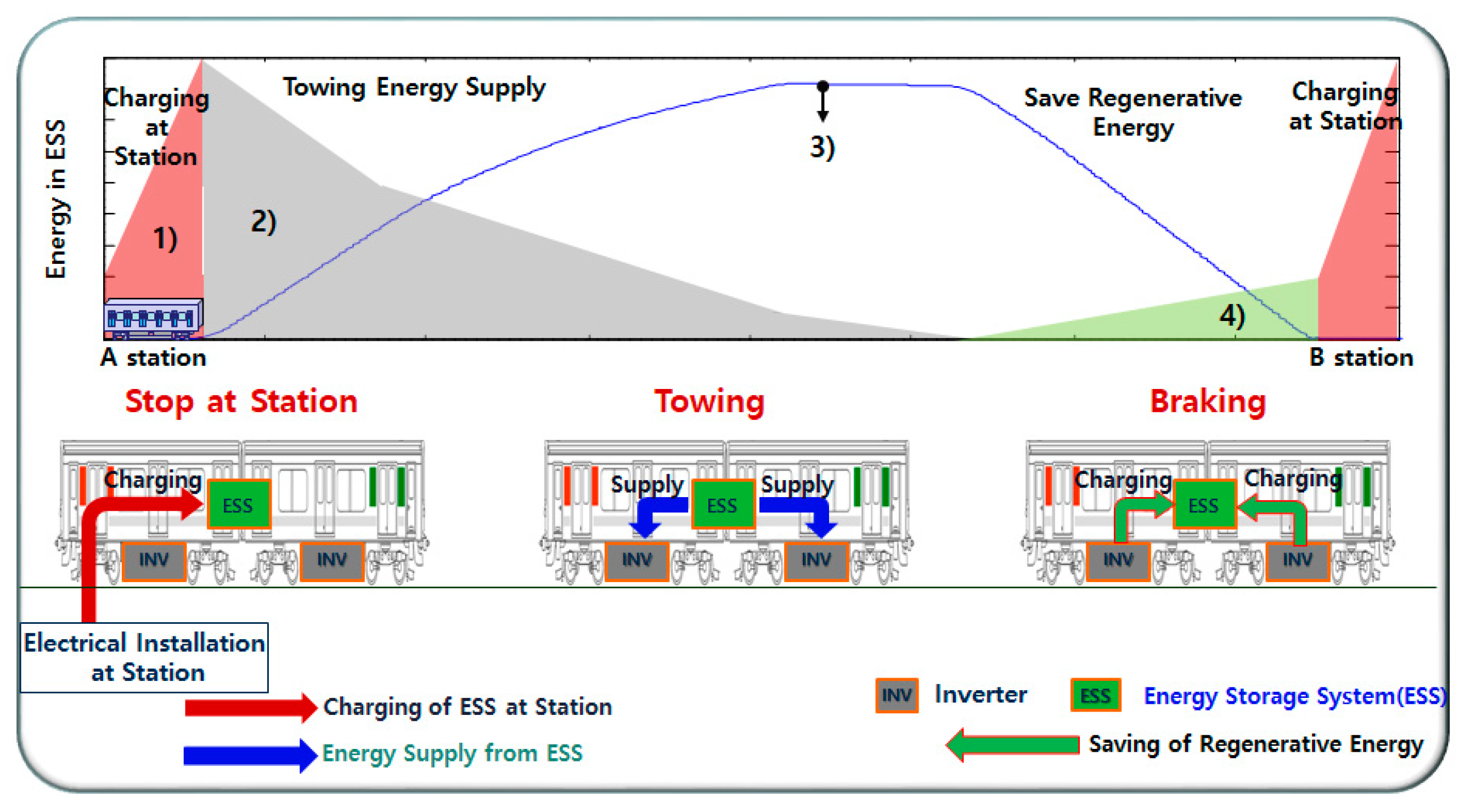
Across the globe, the advancement of the large-capacity battery technology has triggered specific studies on the wireless railway vehicles using the high-speed charging technology, instead of relying on the power supply of the overhead lines. Bombardier’s light-rail vehicles in Mannheim, Germany use the ESSs equipped with an electric double layer capacitor (EDLC) and utilize the method of charging the batteries from a DC overhead line voltage with 750 V. Germany’s Siemens is now carrying out a trial operation of its railway vehicles by using supercapacitors and employing the method of charging the batteries from a DC overhead line voltage with 750 V. Alstom successfully commissioned the hybrid light-rail vehicles using the Ni-MH batteries in Nice, France. In Korea, as shown in Figure 1, the Korea Railroad Research Institute (KRRI) strives to achieve the technologies that enable trains to run without trolley wires, while storing the necessary energy in its supercapacitor by high-speed charging, for the inter-station journey (within 20 s and at 1500 V DC). The high-speed charging occurs during a standstill at a station and the absorption of the regenerative braking energy [27]. Research and development are currently underway to enable a train to run up to 2 km without the overhead wires, and its testing is scheduled to begin in 2017, by mounting batteries on a real train (railway vehicles).
Figure 1 shows the charging and discharging of the ESS in the train. The ESS is charged when the train stops at the station. The charged energy is discharged to supply the power to the inverter during the operation of the train. The energy generated by the regenerative braking, to stop the train at the next station, is charged in the ESS. This process is represented as a graph in Figure 1. In Figure 1, (1), (2), and (4) shows the variation of energy in the ESS during the train’s operation from station A to station B. Figure 1 (1) shows the energy charged in the ESS when the train stops at the station. Figure 1 (2) shows that the energy in the ESS is used for the operation of the train. Figure 1 (4) shows the energy generated by the regenerative braking while stopping is used to charge the ESS. Further, Figure 1 (3) shows the variation of energy used for the operation of the train.
2.2. T2G System
The T2G system is similar to the more commonly known V2G system. Figure 2 illustrates the T2G system using the wireless railway vehicles. The T2G system exhibits a reverse power transmission from the batteries in a train to the electric power grid when the train is not operating. The T2G system uses the wireless railway vehicles. It means a system designed to transmit energy to the electric power grid using the energy stored in the ESS in the wireless train is on standby, i.e., is not presently operating. The wireless trains are the ones being operated with an ESS like that of an EV. The KRRI is currently undertaking the development of such vehicles [26,27].
Figure 3 shows the conventional power conversion equipment in an urban railroad station and the on-board power conversion device in a train. The 3-phase 22.9 kV voltage input into the power distribution facilities in the station is converted to the 3-phase 6.6 kV voltage through the step-down transformer, and this voltage passes through the diode rectifier, thereby generating 1500 V DC. The conventional power transformation facilities in the railroad stations are characterized by a unidirectional system in which the electric power is unilaterally supplied from the power distribution network to the train. Thus they have limitations in reversely transmitting the energy stored on-board to the power distribution network. To transmit the power stored in the ESS of a train to the electric power grid, it is necessary to set up an additional system for the reverse power transmission.
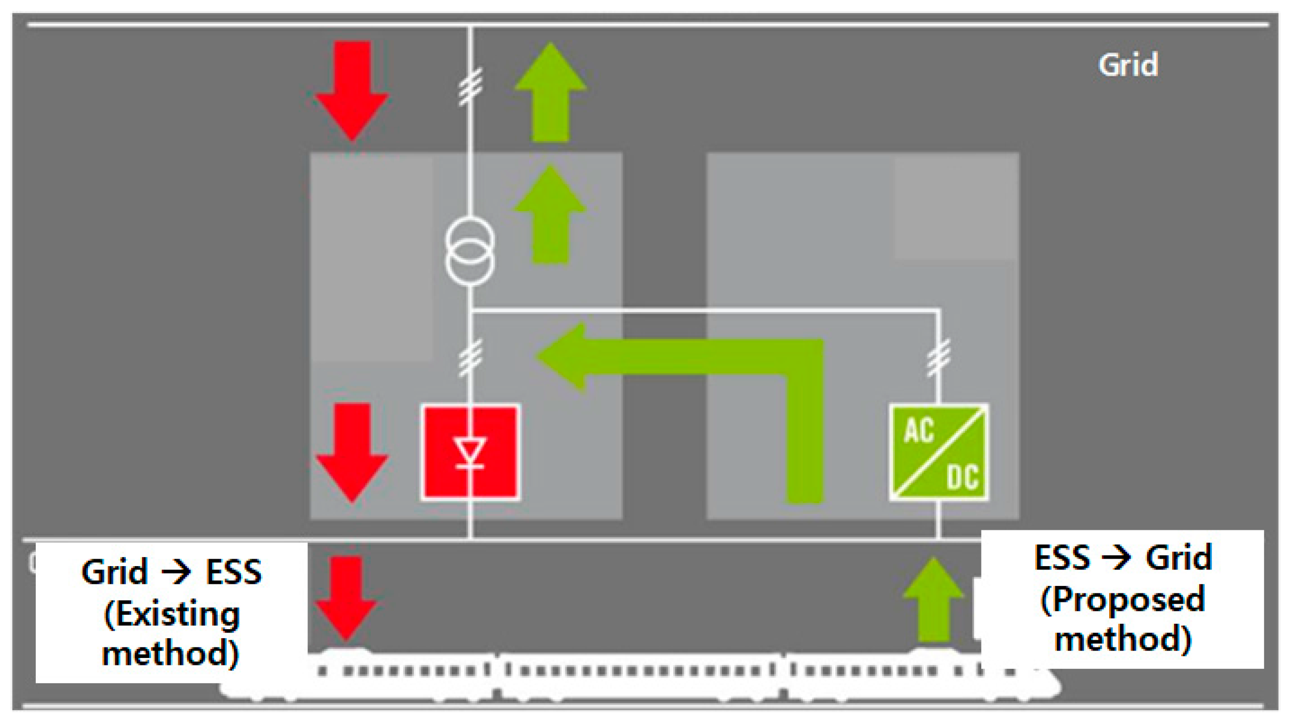
Figure 4 shows a system with power conversion facilities that are capable of bidirectional power supply in a railroad station using the T2G system. To utilize the conventional facilities and minimize any additional system installations, a DC/AC inverter for reverse power transmission has been set up at the diode rectifier as a bypass. This enables the system to transmit the electric power through the diode rectifier in the system operation, transmitting the electric power from the grid to the train. The direction of the power flow in this case is represented as a dash line in Figure 4. The power is supplied from grid to train through the diode rectifier. In the system operation of transmitting the sending electric power from the train to the grid, it operates to cut off the DC contact in the direction of the diode rectifier and reverse transmit the electric power through the inverter. The direction of the power flow in this case is represented as a solid line in Figure 4. The power from the train to the grid is supplied through the inverter.
2.3. Calculation of the ESS Capacity of a Wireless Train for High-Speed Charging
For a wireless train using an ESS, i.e., not the ones receiving the electric power from the overhead lines, it is crucial to estimate the ESS capacity. In this paper, the ESS capacity was estimated by applying the amount of electric power used by the Korean urban railroads. Table 1 shows the amounts of electric power consumed by the Urban Railroad Line No. 2, 3, and 4, which were measured by the Korean Urban Railroad Corporation.
Maxwell’s supercapacitor modules were used for the wireless train with the ESS designed in this paper. The supercapacitor modules were set up by connecting 18 capacitors in series. Each module had a voltage of 48.6 V and a capacitance of 165 F. The wireless railway vehicles currently being researched by the KRRI have 1500 VDC. Therefore, the 32 supercapacitor modules are connected in series, thereby setting them to 1500 VDC. The usable energy before the reverse power transmission is assumed to be 55% of the maximum amount of the charge stored.
- -
- Voltage of the 32 modules connected in series:
- -
- Supercapacitor capacitance of the 32 modules:
- -
- Maximum supercapacitor energy quantity of the 32 modules:
- -
- Maximum available supercapacitor energy quantity of the 32 modules:
Table 2 shows that the ESS capacity was estimated using the above calculations and the amount of energy. When a train runs for 1 km, the average energy consumption is about 25 kWh. The average distance between one railroad station and another station in Korea is about 2 km, and hence the average energy consumption between them is about 50 kWh. Therefore, in this paper, the maximum available amount of energy was set to 100 kWh considering the power reserve. Further, the available amount of energy for T2G was set to 60.31 kWh. The ESS capacity for the wireless railway vehicles for high-speed charging is presented in Table 2.
3. Composition of Electricity Prices for Korean Urban Railroads
The electricity prices for the Korean urban railroads are charged diversely based on the electricity prices publicly announced by the Korea Electric Power Corporation (KEPCO). KEPCO promulgates the electricity prices, divided into the various price segments according to the utilization areas, of use such as general, industrial, residential, educational, agricultural, and demand management purposes. The electricity prices are also calculated differently according to the season and the time-period classification. Therefore, each railroad company simulates various electricity pricing systems and then chooses the most favorable one. The railroad companies use industrial electric power. They can choose (A) or (B) for industrial electric power according to the size of their usage. The industrial electric power is classified into A, B, and C according to voltage sizes. Additionally, they select option I, II, or III according to the time of use and then choose and pay the lowest electricity prices. Table 3 shows the industrial electric power in the electricity pricing systems published by KEPCO. Table 4 shows the time periods classified by season and load capacity by KEPCO. The electricity prices, applicable to the subways of the Korean urban railroad, are charged by choosing the industrial electric power (B), high-voltage A, and option II [38].
The electricity prices applied by the Korea Urban Railroad Corporation are classified into the demand and energy charges. The demand charges are based on the highest power consumption among the electric power used for one year, whereas the energy charges are based on the hourly power consumption. Equation (1) shows a calculation method of the electricity price.
Electricity price = demand charge + energy charge
The demand charges are calculated based on the highest peak power in the 12 months of the previous year. The peak power means the highest of the electric power quantities used for 15 min between 12 a.m. and 11 p.m. The only method to save on demand charges is to reduce the highest peak power value in 12 months. Equation (2) shows the calculation method of the demand charge.
Energy charges are determined based on the electric power quantity consumed per hour by urban railroads and the time-of-use (TOU) pricing system. Equation (3) shows the calculation method of the energy charge. One method to reduce energy charges is by decreasing the power consumption when the TOU price is high.
Section 3 presents the composition of electricity prices for the Korean urban railroads. Based on this, Section 4 proposes a reduction method of electricity prices based on T2G system. The data shown in Table 3 and Table 4 can be used for the simulations of the proposed method. The assumptions and parameters used to simulate the proposed method are as follows:
- -
- The method to reduce both demand and energy charges will be proposed.
- -
- In simulations, the prices corresponding to the demand charge in Table 3 are substituted into in (6), which is the new calculation equation of the electricity prices based on the T2G system.
- -
- Because the simulations are performed using the summer data, the prices corresponding to the summer in the energy charge of Table 3 ar substituted into in (6).
- -
- The simulations are performed on 24 h basis. The classifications of the off-peak, mid-peak, and on-peak time among 24 h are presented in Table 4.
4. Reduction Method of Electricity Prices Using T2G
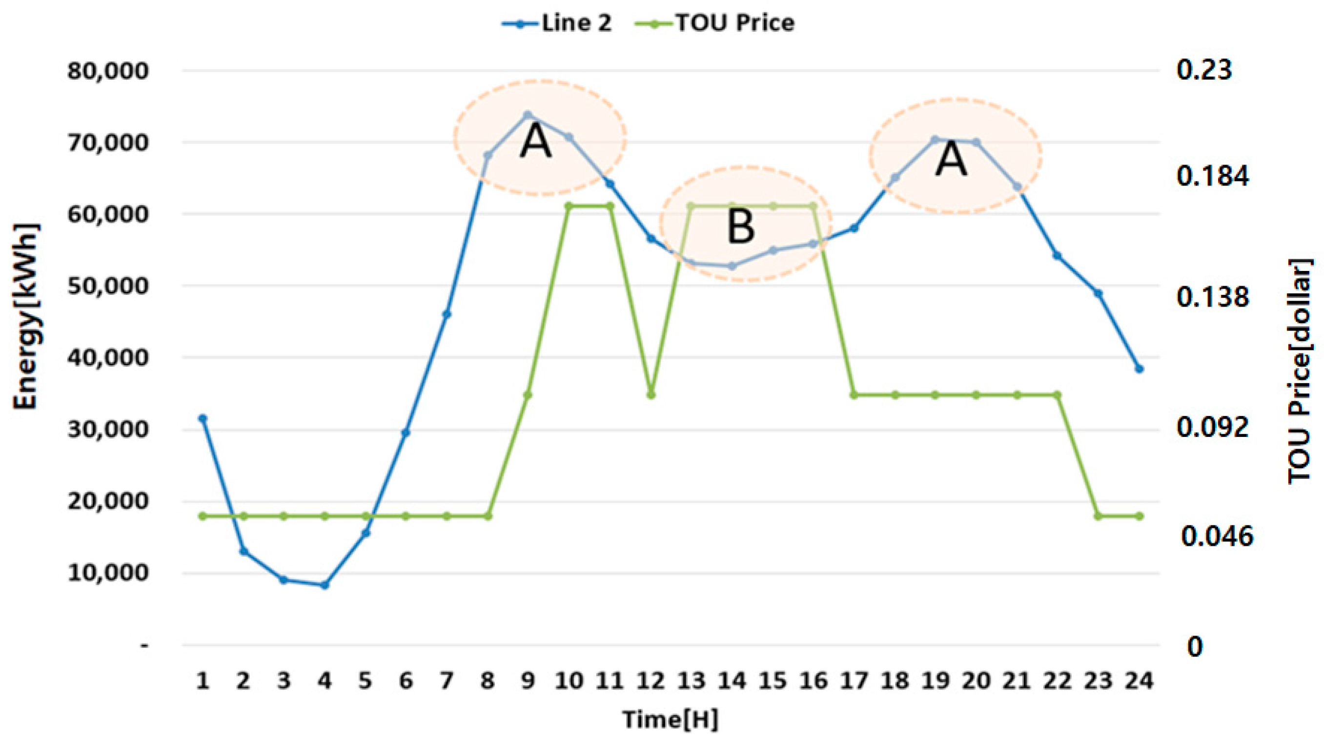
The hourly peak power consumption for the Korean urban railroads has a different time period from that of the highest TOU price as shown in Figure 5. Therefore, if the power consumption is controlled during the time period when the TOU price is at its highest, it is possible to reduce both the demand charge and the energy charge at the same time. In other words, by lowering the power quantity of area A and the power quantity of area B, as shown in Figure 5, the demand charge by decreasing the peak power quantity and the energy charge by decreasing the hourly power consumption can be reduced simultaneously. The composition of the electricity prices is classified into demand charges and energy charges. Accordingly, reducing both demand charges and energy charges is the most efficient method to decrease the electricity prices for the Korean urban railroads. Therefore, this paper proposes a method for simultaneously reducing both demand and energy charges by introducing the T2G system using the wireless railway vehicles.
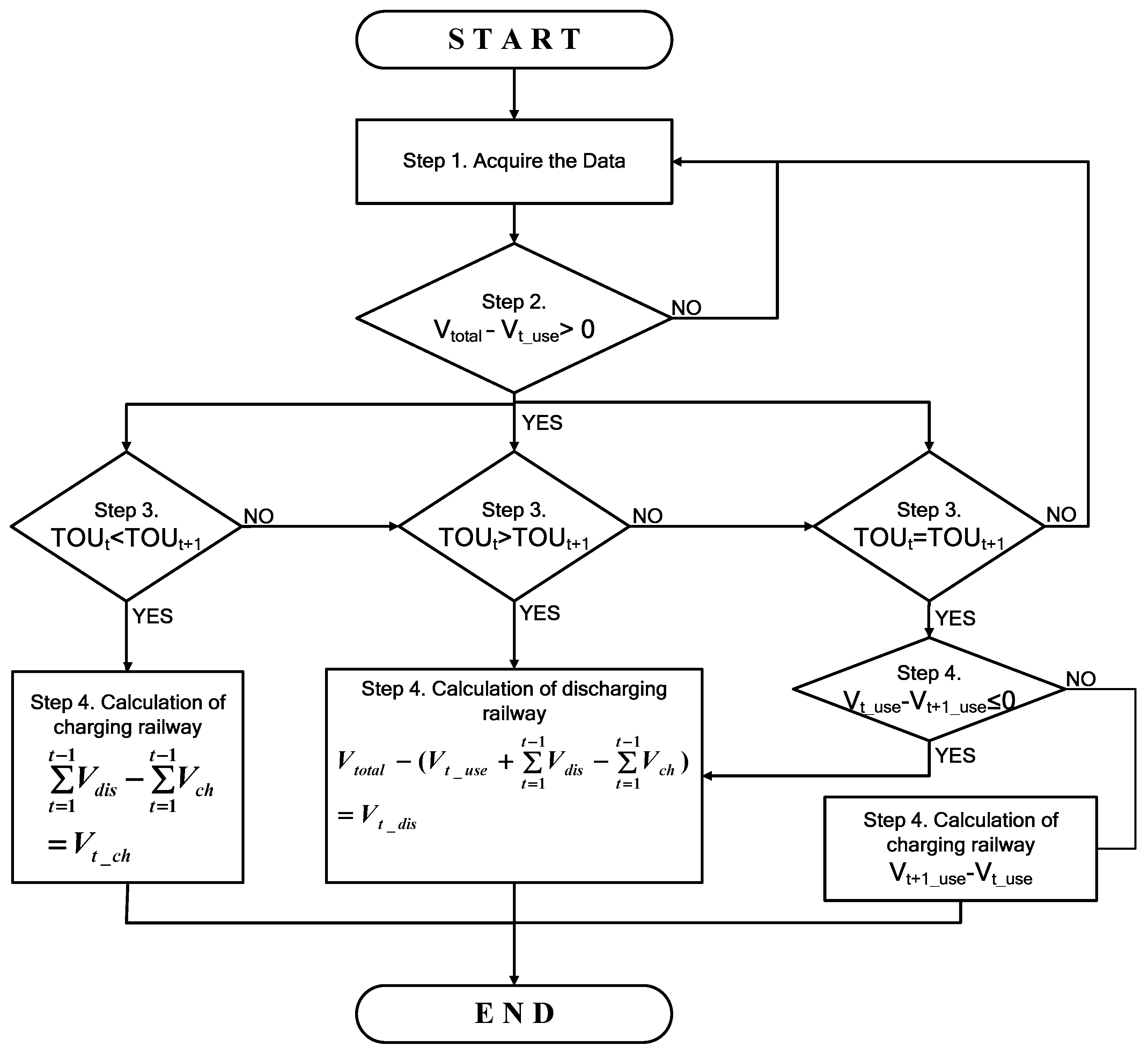
To utilize the T2G system, this paper proposed an algorithm to calculate the number of railway vehicles to battery charge or discharge through T2G as shown in Figure 6. The first step of the T2G algorithm is collecting the real data on the urban railroads (the total number of railway vehicles for operation, the number of railway vehicles for operation at each scheduled time, and TOU). The second step is to judge whether battery charging and discharging can be performed by comparing the total number of railway vehicles for operation (Vtotal) with the number of railway vehicles for the operation at each scheduled time (Vt_use). The third step is to determine the time for the battery charging and discharging (reverse power transmission) by comparing the electricity prices at the present time (t time) (TOUt) with the electricity prices at the next time (t + 1 time) (TOUt+1) by the means of the TOU prices. If TOUt+1 is higher than TOUt, it is set to charge the railways at the current time. If TOUt is more expensive than TOUt+1, it is set to discharge the railways at the current time. If the price is same, it is set to charge or discharge after confirming other conditions. The fourth step is to calculate the number of available railway vehicles for battery charging (power grid → vehicle ESS) and reverse power transmission (vehicle ESS → power grid) based on the TOU pricing system. If it is decided to charge the railways in step 3, the number of railways to be charged is determined by (4). The number of railways that must be charged at the current time can be calculated by subtracting the number of charged railways from the number of discharged railways until previous time. If it is decided to discharge the railways in step 3, the number of railways to be discharged is determined by (5). The number of railways that can be discharged is obtained by subtracting the number of railways operating at t time (Vt_use) and the number of railways that must be charged (Vt_ch) from the total number of railways (Vtotal). In case the same pricing system applies to both the t + 1 time and the t time in step 3, the railway vehicles currently running at the present time (t time) (Vt_use) and the railway vehicles scheduled to run at the next time (t + 1 time) (Vt+1_use) are compared to check for the possibility of battery charging and reverse power transmission. If Vt+1_use is greater than Vt_use, the number of railways to be charged is determined, since charging is necessary. If Vt+1_use is less than Vt_use, the number of railways to be discharged is determined
Equation (4) is the formula for calculating the number of railway vehicles that are charged during the time period when energy charges decrease. Equation (5) is the formula for calculating the number of railway vehicles available for use for the reverse power transmission during the time period when the energy charges increase. The number of railway vehicles undergoing battery charging and discharging during each time period is calculated using (4) and (5). Further, the electricity prices based on T2G are calculated using (6). The first term of (6) is intended to calculate the demand charge based on T2G, and the second term is designed to calculate the energy charge for each time period.
5. Simulation Results
The simulations were performed to verify the reduction method of electricity prices using T2G. Additionally, an experiment closer to reality was carried out by employing the real data on the Korean urban railroad Line No. 2, 3, and 4.
5.1. Number of Korean Urban Railway Vehicles Scheduled for Operation at Each Scheduled Time
In this paper, it is necessary to clarify the number of railway vehicles placed on standby in the station for the reverse power transmission using T2G. The Korea urban railroad sets the number of railway vehicles intended to start running at each scheduled time and operates railway vehicles accordingly. Therefore, the time schedules for the urban railroad lines were used to calculate the number of railway vehicles capable of the reverse power transmission using T2G. Table 5 shows the number of railway vehicles intended to run at each scheduled time in each urban railroad line. Most of the railway vehicles are seen to be scheduled to run during commuting hours, i.e., between 7 a.m. and 9 a.m. or between 5 p.m. and 7 p.m. A total of 88 railway vehicles are available for the operation according to the schedule in the Korean urban railroad Line No. 2; 49 railway vehicles in Line No. 3; and 47 railway vehicles in Line No. 4. The numbers of railway vehicles scheduled to be placed on standby in the station at each time can be calculated as the difference between total number of railway and that in Table 5 at each time.
5.2. Variations of Electric Energy Consumption in Each Korean Urban Railroad Line by the Proposed Method
The proposed method is designed to reduce both demand and energy charges. Therefore, the number of railway vehicles reverse transmitting the energy may be changed depending on the TOU price. Table 6 shows the number of railway vehicles in each urban railroad line for charging and discharging determined based on the T2G system and the TOU price. It displays not only the railway vehicles operated for T2G during the time period of 9–10 a.m. when the highest peak occurs, but also the ones operated for T2G according to the electricity prices during each time period.
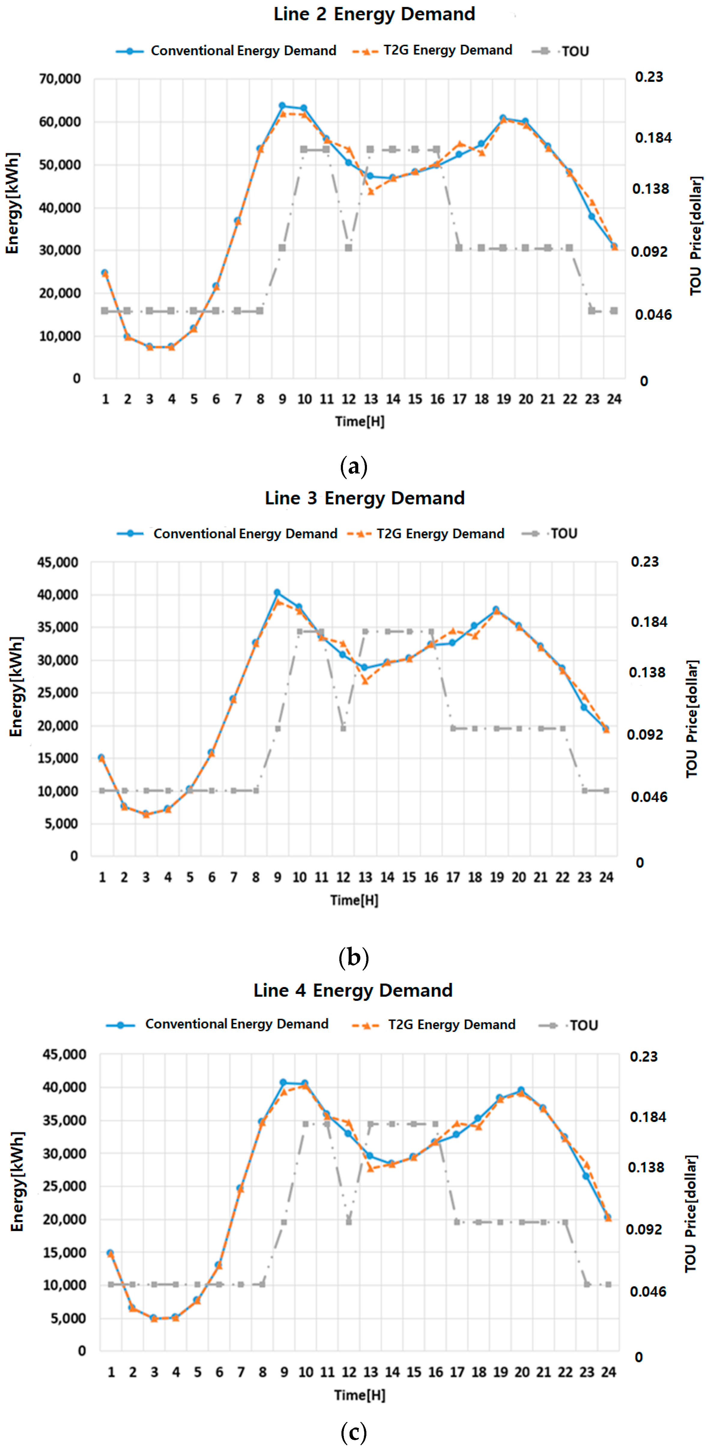
Table 7 and Figure 7 shows the conventional energy consumption and the energy consumption in the proposed method using T2G. Table 7 and Figure 7 also reveal that the highest peak energy in the proposed method decreases more compared to the one in the conventional energy demand and the energy consumption changes according to the real-time electricity prices. Additionally, by charging the railway vehicles at the time when electricity prices are relatively low, the energy consumption tends to increase during each time period when the TOU price is low and decreases during each time period when the TOU price is high.
5.3. Reduction of Electricity Prices by the Proposed Method
This paper calculated the electricity prices for August in 2016 using (1) and the real data on the power consumption of August in 2016. The electricity prices for the urban railroads at that time were calculated by dividing them into the demand charges and the energy charges. The demand charges were calculated using the highest peak power for each urban railroad line, and the energy charges were calculated by applying the TOU price and power quantity data. To establish the least favorable conditions, this paper used the power data of the day with the highest peak power in 2016. Therefore, the electricity prices of that day were calculated, and then they were converted to monthly electricity prices.
Table 8 show the electricity prices for August in 2016. This table shows the electricity prices calculated without using the reduction method of the electricity prices, and those calculated using the reduction method of the electricity prices by the proposed method for Urban Railroad Line No. 2, 3, and 4. The proposed method indicates that the electricity prices in Line No. 2, 3, and 4 are reduced by 0.87%, 0.74%, and 0.74%, respectively. The actual amounts by which the electricity prices were reduced are $30,176 for Line No. 2, $18,464 for Line No. 3, and $18,922 for Line No. 4. This means that $67,553 in the electricity prices can be approximately saved per month by implementing the proposed method of this research. If this monthly amount is converted to an annual amount, a significant amount of about $810,000 can be saved annually in the electricity bills. The reduction in the total annual electricity prices is evident, as seen in the following results: about $362,112 reduction for Line No. 2, about $221,568 for Line No. 3, and about $227,064 for Line No. 4. This is because the proposed method can allocate the power consumption by decreasing the power consumption when the TOU price is high and by charging batteries of railway vehicles when the TOU price is low.
To present the theoretical proof of simulation results for the performance of the proposed T2G system, this paper shows the calculation process of demand charge as an example.
- -
- ConditionsLine: No. 2, Time: 9
- -
- Conventional MethodEnergy consumption: 63,789 kWhDemand charge: 7.8 $/kWh × 63,789 kWh = $497,554
- -
- Proposed methodNumber of railway vehicles available for use for reverse power transmission: 31Energy Consumption: 63,789 kWh − 31 × 60.31 kWh = 61,919 kWhDemand charge: 7.8 $/kWh × 61,919 kWh = $482,968
To carry out the simulations using the data of one year, the data for one year are required. The data to be required are the total number of railway vehicles for operation in one year, the number of railway vehicles for operation at each scheduled time during one year, and TOU. It is practically impossible to obtain all this data. Therefore, in this paper, the simulations are performed using the data of August 2016 to verify the method proposed in this study. Even if the simulations are performed using all the data of one year, the reduction ratio of electricity prices compared with the conventional electricity prices is not expected to change significantly. The reasons are that first, the capacity of ESS in each railway is the same, and second, the number of railways under operation does not change from January to December. Therefore, the effectiveness of the proposed method using T2G can be verified with data of one month.
6. Conclusions
This paper introduces the T2G system using the wireless railway vehicles with a large-capacity ESS, and proposes the reduction method of the electricity prices using the T2G system. The electricity prices are calculated by the summation of the demand and energy charges. Therefore, this paper proposes the reduction method of the electricity prices by lowering both demand and energy charges. The proposed method is designed to reduce the electricity prices by decreasing the peak power and the hourly power consumption for the A and B parts marked in Figure 5. An algorithm for determining the number of railways to be charged or discharged is also proposed. The proposed algorithm determines charging or discharging based on TOU price change. If it is decided to charge, the number of railways to be charged is determined by (4), and if it is decided to discharge, the number of railways to be discharged is determined by (5). The change of total power consumption is calculated by the number of railways that are charged or discharged multiplied by the capacity of the ESS and then the electricity price is calculated.
To test the proposed method, the simulations are performed using real data on the Korean urban railroad Line No. 2, 3, and 4. Also, to verify the superiority of the proposed method, the simulation results are compared with the conventional electricity prices. The total electricity prices per month are decreased by 0.75% for Line No. 2, by 0.74% for Line No. 2, and by 0.74% for Line No. 4.
It presents that both demand and energy charges are decreased slightly. These results are from the characteristics of wireless railway vehicles capable of high-speed charging. The ESSs can only be utilized for power demand distribution, while the wireless railway vehicles are mainly for transportation without being employed solely for power demand distribution. Additionally, this paper did not address the power supplies by regenerative braking, one of the most prominent characteristics of wireless railway vehicles. Therefore, it is concluded that as the size of utilized power is inconsiderable, the electricity prices are presented to be decreased slightly.
By applying both the T2G system and the regenerative energy, more effective energy reduction can be achieved. However, this paper does not apply the regenerative energy to verify that the T2G system can reduce the energy used without using regenerative energy. The scheme using both the T2G system and the regenerative energy will be studied in the future.
This paper presents the applicability and efficiency of the T2G system for the management and operation of the power demand in the railroad industry. Two challenges to realize the proposed method should be considered. The first challenge is the cost problem. The electric installation should be additionally introduced between the train and the power grid. Further, the costs of batteries for trains should be considered. This will require a high cost. The second challenge is the impact on the power system during the discharging of railways. By the reverse power transmission from a train, the problems of power flow, power quality, protection, etc., may occur. Therefore, the impact on the power system should be investigated and the countermeasures for the same should be developed.
In future, we will study the practical applications of the T2G system considering these factors.
Acknowledgments
This research was supported by a grant from R&D Program of the Korea Railroad Research Institute, Republic of Korea.
Author Contributions
Hyo-Sang Go conceived and designed the idea. Hyo-Sang Go, In-Ho Cho, and Gil-Dong Kim performed the experiments and analyzed the data. Hyo-Sang Go and Chul-Hwan Kim wrote the paper.
Conflicts of Interest
The authors declare no conflict of interest
Nomenclature
| Basic charge | |
| Highest peak power in 12 months | |
| Number of months | |
| Electric rate per hour based on the TOU price | |
| Power consumption per hour | |
| Number of railway being used for reverse power transmission | |
| Number of railway being charged | |
| Number of railway being charged at t time | |
| Total number of railway | |
| Number of railway operating at t time | |
| Number of railway operating at next time | |
| Number of railway being used for reverse power transmission at t time | |
| Time-of-use at t time | |
| Time-of-use at next time | |
| Usable ESS capacity of wireless railway vehicles |
References
- Rahman, I.; Vasant, P.M.; Singh, B.S.M.; Abdullah-Al-Wadud, M.; Adan, N. Review of recent trends in optimization techniques for plug-in hybrid, and electric vehicle charging infrastructures. Renew. Sustain. Energy Rev. 2016, 58, 1039–1047. [Google Scholar] [CrossRef]
- Gan, L.; Topcu, U.; Low, S.H. Optimal decentralized protocol for electric vehicle charging. IEEE Trans. Power Syst. 2013, 28, 940–951. [Google Scholar] [CrossRef]
- Liu, Z.; Wen, F.; Ledwich, G. Optimal planning of electric-vehicle charging stations in distribution systems. IEEE Trans. Power Deliv. 2013, 28, 102–110. [Google Scholar] [CrossRef]
- Leou, R.-C.; Su, C.-L.; Lu, C.-N. Stochastic analyses of electric vehicle charging impacts on distribution network. IEEE Trans. Power Syst. 2014, 29, 1055–1063. [Google Scholar] [CrossRef]
- Mohamed, A.; Salehi, V.; Ma, T. Real-time energy management algorithm for plug-in hybrid electric vehicle charging parks involving sustainable energy. IEEE Trans. Sustain. Energy 2014, 5, 577–586. [Google Scholar] [CrossRef]
- Veldman, E.; Verzijlbergh, R.A. Distribution grid impacts of smart electric vehicle charging from different perspectives. IEEE Trans. Smart Grid 2014, 6, 333–342. [Google Scholar] [CrossRef]
- De Hoog, J.; Alpcan, T.; Brazil, M.; Thomas, D.A.; Mareels, I. A market mechanism for Electric Vehicle charging under network constraints. IEEE Trans. Smart Grid 2016, 7, 827–836. [Google Scholar] [CrossRef]
- Li, R.; Wu, Q.; Oren, S.S. Distribution locational marginal pricing for optimal electric vehicle charging management. IEEE Trans. Power Syst. 2014, 29, 203–211. [Google Scholar] [CrossRef]
- Kim, J.-H.; Kim, C.-H. Smart EVs Charging Scheme for Load Leveling Considering ToU Price and Actual Data. J. Electr. Eng. Technol. 2017, 12, 1–10. [Google Scholar] [CrossRef]
- Go, H.-S.; Ryu, J.-H.; Kim, J.; Kim, G.-D.; Kim, C.-H. New Prediction of the Number of Charging Electric Vehicles Using Transformation Matrix and Monte-Carlo Method. J. Electr. Eng. Technol. 2017, 12, 451–458. [Google Scholar] [CrossRef]
- Amini, M.H.; Kargarian, A.; Karabasoglu, O. ARIMA-based decoupled time series forecasting of electric vehicle charging demand for stochastic power system operation. Electr. Power Syst. Res. 2016, 140, 378–390. [Google Scholar] [CrossRef]
- Melhorn, A.C.; McKenna, K.; Keane, A.; Flynn, D.; Dimitrovski, A. Autonomous plug and play electric vehicle charging scenarios including reactive power provision: A probabilistic load flow analysis. IET Gener. Transm. Distrib. 2017, 11, 768–775. [Google Scholar] [CrossRef]
- Vachirasricirikul, S.; Ngamroo, I. Robust LFC in a smart grid with wind power penetration by coordinated V2G control and frequency controller. IEEE Trans. Smart Grid 2014, 5, 371–380. [Google Scholar] [CrossRef]
- Kavousi-Fard, A.; Niknam, T.; Fotuhi-Firuzabad, M. Stochastic reconfiguration and optimal coordination of V2G plug-in electric vehicles considering correlated wind power generation. IEEE Trans. Sustain. Energy 2015, 6, 822–830. [Google Scholar] [CrossRef]
- Alam, M.J.E.; Muttaqi, K.M.; Sutanto, D. Effective utilization of available PEV battery capacity for mitigation of solar PV impact and grid support with integrated V2G functionality. IEEE Trans. Smart Grid 2016, 7, 1562–1571. [Google Scholar] [CrossRef]
- Kumar, K.N.; Sivaneasan, B.; Cheah, P.H.; So, P.L.; Wang, D.Z.W. V2G capacity estimation using dynamic EV scheduling. IEEE Trans. Smart Grid 2014, 5, 1051–1060. [Google Scholar] [CrossRef]
- Christian Chukwu, U.C.; Mahajan, S.M. Real-time management of power systems with V2G facility for smart-grid applications. IEEE Trans. Sustain. Energy 2014, 5, 558–566. [Google Scholar] [CrossRef]
- Mendes, P.R.C.; Valver deIsorna, L.; Bordons, C.; Normey-Rico, J.E. Energy management of an experimental microgrid coupled to a V2G system. J. Power Sources 2016, 327, 702–713. [Google Scholar] [CrossRef]
- Tang, Y.; Zhong, J.; Bollen, M. Aggregated optimal charging and vehicle-to-grid control for electric vehicles under large electric vehicle population. IET Gener. Trans. Distrib. 2016, 10, 2012–2018. [Google Scholar] [CrossRef]
- Karfopoulos, E.L.; Hatziargyriou, N.D. Distributed coordination of electric vehicles providing V2G services. IEEE Trans. Power Syst. 2016, 31, 329–338. [Google Scholar] [CrossRef]
- Tan, K.M.; Ramachandaramurthy, V.K.; Yong, J.Y. Integration of electric vehicles in smart grid: A review on vehicle to grid technologies and optimization techniques. Renew. Sustain. Energy Rev. 2016, 53, 720–732. [Google Scholar] [CrossRef]
- Go, H.S.; Kim, D.-U.; Kim, J.-H.; Lee, S.-J.; Kim, S.-K.; Kim, E.-S.; Kim, C.-H. A Study on Voltage Sag Considering Real-Time Traffic Volume of Electric Vehicles in South Korea. J. Electr. Eng. Technol. 2015, 10, 1492–1501. [Google Scholar] [CrossRef]
- Peng, C.; Zou, J.; Lian, L.; Li, L. An optimal dispatching strategy for V2G aggregator participating in supplementary frequency regulation considering EV driving demand and aggregator’s benefits. Appl. Energy 2017, 190, 591–599. [Google Scholar] [CrossRef]
- Lam, A.Y.S.; Leung, K.-C.; Li, V. Capacity estimation for vehicle-to-grid frequency regulation services with smart charging mechanism. IEEE Trans. Smart Grid 2016, 7, 156–166. [Google Scholar] [CrossRef]
- Manbachi, M.; Farhangi, H.; Palizban, A.; Arzanpour, S. A novel Volt-VAR Optimization engine for smart distribution networks utilizing Vehicle to Grid dispatch. Int. J. Electr. Power Energy Syst. 2016, 74, 238–251. [Google Scholar] [CrossRef]
- Go, H.-S.; Cho, I.-H.; Ryu, J.-H.; Kim, G.-D. Study of Electric Charge Saving Plan Using High-speed Charging Wireless Railway System. J. Korean Soc. Railw. 2017, 20, 31–42. [Google Scholar] [CrossRef]
- Kim, G.-D.; Lee, J.-M.; Han, Y.-J.; Ryu, J.-H. Development of Wireless Train Power Supply Technology Using 1MW—Class High Speed Electric Power Charge Storage; Korea Railroad Research Institute: Uiwang, Korea, 2015. [Google Scholar]
- Steiner, M.; Klohr, M.; Pagiela, S. Energy storage system with ultracaps on board of railway vehicles. In Proceedings of the European Conference on Power Electronics and Applications, Aalborg, Denmark, 2–5 September 2007. [Google Scholar]
- Richardson, M.B. Flywheel energy storage system for traction application. In Proceedings of the International Conference on Power Electronics, Machines, and Drives, Sante Fe, NM, USA, 4–7 June 2002. [Google Scholar]
- Kampeerawat, W.; Koseki, T. A strategy for utilization of regenerative energy in urban railway system by application of smart train scheduling and wayside energy storage system. Energy Procedia 2017, 138, 795–800. [Google Scholar] [CrossRef]
- Roch-DupréÁlvaro, D.; López-López, J.; Pecharromán, R.R.; Cucala, A.P.; Fernández-Cardador, A. Analysis of the demand charge in DC railway systems and reduction of its economic impact with Energy Storage Systems. Int. J. Electr. Power Energy Syst. 2017, 93, 459–467. [Google Scholar] [CrossRef]
- Ratniyomchai, T.; Hillmansen, S.; Tricoli, P. Recent developments and applications of energy storage devices in electrified railways. IET Electr. Syst. Transp. 2014, 4, 9–20. [Google Scholar] [CrossRef]
- Kim, H.; Heo, J.-H.; Park, J.-Y.; Yoon, Y.T. Impact of Battery Energy Storage System Operation Strategy on Power System: An Urban Railway Load Case under a Time-of-Use Tariff. Energies 2017, 10, 68. [Google Scholar] [CrossRef]
- Ghaviha, N.; Campillo, J.; Bohlin, M.; Dahlquist, E. Review of Application of Energy Storage Devices in Railway Transportation. Energy Procedia 2017, 105, 4561–4568. [Google Scholar] [CrossRef]
- Using Trains to Send Power to the Grid. Available online: https://www.asme.org/engineering-topics/articles/energy/using-trains-send-power-grid (accessed on 19 February 2018).
- Available online: https://www.aresnorthamerica.com/article/8957-railway-solution-for-grid-scale-energy-storage (accessed on 19 February 2018).
- Available online: http://www.seoulmetro.co.kr (accessed on 19 February 2018).
- Available online: http://www.kepco.co.kr (accessed on 19 February 2018).
Figure 1.
Wireless railway vehicles using the high-speed charging technology.

Figure 2.
T2G system using wireless railway vehicles.

Figure 3.
Conventional transforming substation.
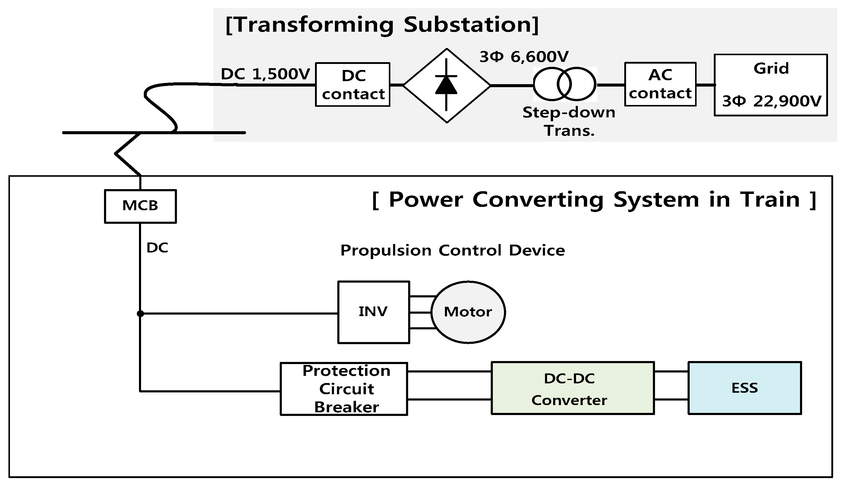
Figure 4.
Proposed transforming substation for T2G.
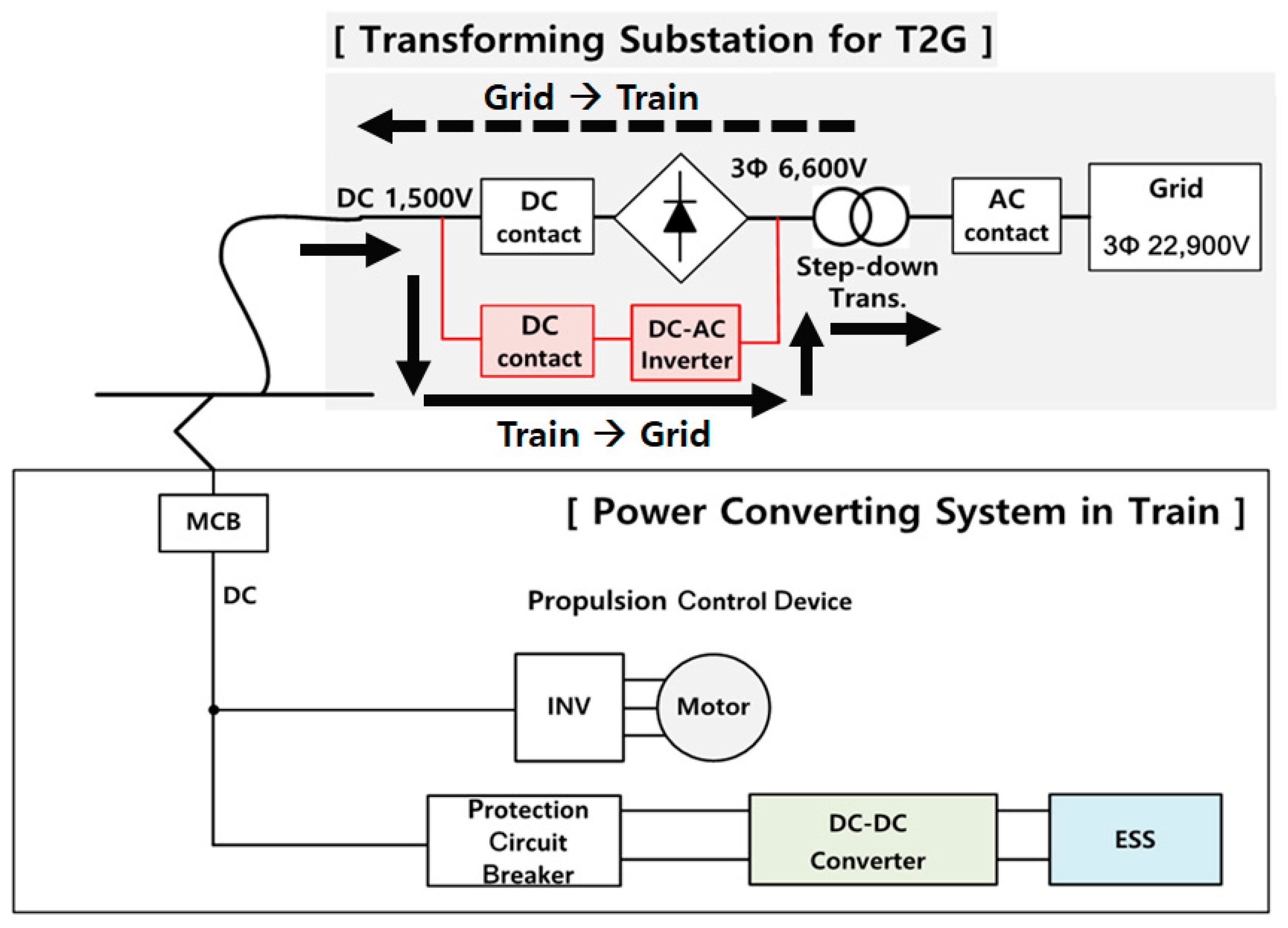
Figure 5.
Energy demand and electricity price (TOU price) of Line 2.

Figure 6.
Algorithm to calculate the number of railway vehicles to battery charge or discharge through T2G.
Figure 6.
Algorithm to calculate the number of railway vehicles to battery charge or discharge through T2G.

Figure 7.
Energy demand at the conventional and proposed method. (a) Energy demand and electricity price in Line 2; (b) energy demand and electricity price in Line 3; (c) energy demand and electricity price in Line 4.
Figure 7.
Energy demand at the conventional and proposed method. (a) Energy demand and electricity price in Line 2; (b) energy demand and electricity price in Line 3; (c) energy demand and electricity price in Line 4.

Table 1.
Energy consumption of the urban railroads [37].
Table 1.
Energy consumption of the urban railroads [37].
| Item | Line 2 | Line 3 | Line 4 | Note |
|---|---|---|---|---|
| Number of trains | 10 | 10 | 10 | - |
| Distance | 48.8 km | 38.2 km | 31.7 km | - |
| Energy consumption | 1220 kWh | 955 kWh | 793 kWh | Energy required for one-way |
Table 2.
ESS capacity of the wireless railway vehicles [26].
Table 2.
ESS capacity of the wireless railway vehicles [26].
| Item | Value |
|---|---|
| Maximum Energy Capacity | 109.65 kWh |
| Available Energy Capacity | 60.31 kWh |
| Voltage | 1555 V DC |
Table 3.
Charging fee for the railway vehicles [38].
Table 3.
Charging fee for the railway vehicles [38].
| Classification | Demand Charge ($/kWh) | Energy Charge ($/kWh) | ||||
|---|---|---|---|---|---|---|
| Time | Summer | Spring/Fall | Winter | |||
| High-Voltage A | Option II | 7.8 | Off-Peak | 0.053 | 0.053 | 0.059 |
| Mid-Peak | 0.102 | 0.074 | 0.102 | |||
| On-Peak | 0.179 | 0.102 | 0.156 | |||
Table 4.
Season and time-period classification [38].
Table 4.
Season and time-period classification [38].
| Classification | Summer (June, July, August) | Spring (March, April, May)/ Fall (September, October) | Winter (November, December, January, February) |
|---|---|---|---|
| Off-Peak | 23:00~09:00 | 23:00~09:00 | 23:00~09:00 |
| Mid-Peak | 09:00~10:00 | 09:00~10:00 | 09:00~10:00 |
| 12:00~13:00 | 12:00~13:00 | 12:00~17:00 | |
| 17:00~23:00 | 17:00~23:00 | 20:00~22:00 | |
| On-Peak | 10:00~12:00 13:00~17:00 | 10:00~12:00 13:00~17:00 | 10:00~12:00 17:00~20:00 22:00~23:00 |
Table 5.
Number of railways scheduled for the operation at each scheduled time.
| Time | Line 2 | Line 3 | Line 4 | Time | Line 2 | Line 3 | Line 4 |
|---|---|---|---|---|---|---|---|
| 1 | - | - | - | 13 | 32 | 16 | 17 |
| 2 | - | - | - | 14 | 32 | 17 | 17 |
| 3 | - | - | - | 15 | 33 | 16 | 16 |
| 4 | - | - | - | 16 | 41 | 17 | 17 |
| 5 | 25 | 5 | 4 | 17 | 52 | 24 | 20 |
| 6 | 44 | 20 | 17 | 18 | 55 | 27 | 27 |
| 7 | 60 | 27 | 26 | 19 | 50 | 25 | 25 |
| 8 | 63 | 33 | 32 | 20 | 39 | 23 | 20 |
| 9 | 57 | 29 | 25 | 21 | 33 | 21 | 19 |
| 10 | 36 | 21 | 20 | 22 | 30 | 18 | 15 |
| 11 | 33 | 18 | 16 | 23 | 24 | 13 | 13 |
| 12 | 32 | 16 | 16 | 24 | 12 | 10 | 6 |
Table 6.
Number of railway vehicles able to be charged and discharged.
| Time | Discharging | Charging | Time | Discharging | Charging | ||||||||
|---|---|---|---|---|---|---|---|---|---|---|---|---|---|
| 2 | 3 | 4 | 2 | 3 | 4 | 2 | 3 | 4 | 2 | 3 | 4 | ||
| 1 | - | - | - | - | - | - | 13 | 56 | 33 | 30 | - | - | - |
| 2 | - | - | - | - | - | - | 14 | - | - | - | - | 1 | - |
| 3 | - | - | - | - | - | - | 15 | - | 1 | 1 | 1 | - | - |
| 4 | - | - | - | - | - | - | 16 | - | - | - | 8 | 1 | 1 |
| 5 | - | - | - | - | - | - | 17 | - | - | - | 47 | 32 | 30 |
| 6 | - | - | - | - | - | - | 18 | 33 | 22 | 20 | - | - | - |
| 7 | - | - | - | - | - | - | 19 | 5 | 2 | 2 | - | - | - |
| 8 | - | - | - | - | - | - | 20 | 11 | 2 | 5 | - | - | - |
| 9 | 31 | 20 | 22 | - | - | - | 21 | 6 | 2 | 1 | - | - | - |
| 10 | 21 | 8 | 5 | - | - | - | 22 | 3 | 3 | 4 | - | - | - |
| 11 | 3 | 3 | 4 | - | - | - | 23 | - | - | - | 58 | 31 | 32 |
| 12 | - | - | - | 55 | 31 | 31 | 24 | - | - | - | - | - | - |
Table 7.
Energy consumption at conventional and proposed method.
| Time | Conventional Energy Consumption (kWh) | Energy Consumption in Proposed Method (kWh) | ||||
|---|---|---|---|---|---|---|
| Line 2 | Line 3 | Line 4 | Line 2 | Line 3 | Line 4 | |
| 1 | 24,684 | 14,957 | 14,855 | 24,684 | 14,957 | 14,855 |
| 2 | 9706 | 7591 | 6488 | 9706 | 7591 | 6488 |
| 3 | 7413 | 6413 | 5023 | 7413 | 6413 | 5023 |
| 4 | 7401 | 7252 | 5080 | 7401 | 7252 | 5080 |
| 5 | 11,766 | 10,163 | 7687 | 11,766 | 10,163 | 7687 |
| 6 | 21,566 | 15,728 | 13,036 | 21,566 | 15,728 | 13,036 |
| 7 | 36,834 | 23,994 | 24,607 | 36,834 | 23,994 | 24,607 |
| 8 | 53,674 | 32,586 | 34,753 | 53,674 | 32,586 | 34,753 |
| 9 | 63,789 | 40,185 | 40,698 | 61,919 | 38,979 | 39,371 |
| 10 | 63,092 | 37,994 | 40,530 | 61,826 | 37,511 | 40,229 |
| 11 | 56,026 | 33,640 | 35,816 | 55,846 | 33,459 | 35,574 |
| 12 | 50,408 | 30,767 | 32,857 | 53,725 | 32,637 | 34,727 |
| 13 | 47,238 | 28,855 | 29,481 | 43,861 | 26,865 | 27,671 |
| 14 | 46,925 | 29,605 | 28,350 | 46,925 | 29,665 | 28,350 |
| 15 | 48,310 | 30,242 | 29,435 | 48,370 | 30,181 | 29,375 |
| 16 | 49,801 | 32,364 | 31,658 | 50,283 | 32,424 | 31,718 |
| 17 | 52,230 | 32,538 | 32,778 | 55,065 | 34,468 | 34,587 |
| 18 | 54,865 | 35,114 | 35,234 | 52,875 | 33,787 | 34,028 |
| 19 | 60,840 | 37,688 | 38,345 | 60,539 | 37,568 | 38,225 |
| 20 | 59,984 | 35,165 | 39,470 | 59,320 | 35,045 | 39,168 |
| 21 | 54,258 | 32,080 | 36,816 | 53,896 | 31,960 | 36,755 |
| 22 | 48,150 | 28,616 | 32,440 | 47,969 | 28,435 | 32,199 |
| 23 | 37,772 | 22,629 | 26,401 | 41,270 | 24,498 | 28,331 |
| 24 | 30,759 | 19,478 | 20,250 | 30,759 | 19,478 | 20,250 |
Table 8.
Electricity Prices of Korea Urban Railway Line 2, 3, and 4.
| Line | Case | Demand Charge ($) | Energy Charge ($) | Total Electricity Price ($) | Reduction Ratio |
|---|---|---|---|---|---|
| Line 2 | Base | 497,554 | 3,530,352 | 4,027,906 | - |
| Proposed method | 482,968 | 3,514,762 | 3,997,730 | 30,176 ($) (0.75% ↓) | |
| Line 3 | Base | 313,349 | 2,193,828 | 2,507,177 | - |
| Proposed method | 303,944 | 2,184,769 | 2,488,713 | 18,464 ($) (0.74% ↓) | |
| Line 4 | Base | 317,346 | 2,256,044 | 2,573,390 | - |
| Proposed method | 307,001 | 2,247,467 | 2,554,468 | 18,922 ($) (0.74% ↓) |
© 2018 by the authors. Licensee MDPI, Basel, Switzerland. This article is an open access article distributed under the terms and conditions of the Creative Commons Attribution (CC BY) license (http://creativecommons.org/licenses/by/4.0/).
Share and Cite
MDPI and ACS Style
Go, H.-S.; Cho, I.-H.; Kim, G.-D.; Kim, C.-H. Reduction of Electricity Prices Using the Train to Grid (T2G) System in Urban Railway. Energies 2018, 11, 501. https://doi.org/10.3390/en11030501
AMA Style
Go H-S, Cho I-H, Kim G-D, Kim C-H. Reduction of Electricity Prices Using the Train to Grid (T2G) System in Urban Railway. Energies. 2018; 11(3):501. https://doi.org/10.3390/en11030501
Chicago/Turabian StyleGo, Hyo-Sang, In-Ho Cho, Gil-Dong Kim, and Chul-Hwan Kim. 2018. "Reduction of Electricity Prices Using the Train to Grid (T2G) System in Urban Railway" Energies 11, no. 3: 501. https://doi.org/10.3390/en11030501
Note that from the first issue of 2016, this journal uses article numbers instead of page numbers. See further details here.