Energy Management Strategy for Micro-Grids with PV-Battery Systems and Electric Vehicles
by
 , and
, and
Jose Luis Torres-Moreno
* ,
,
Antonio Gimenez-Fernandez
,
Manuel Perez-Garcia
and
Francisco Rodriguez
Automatic Control, Robotics and Mechatronics Research Group, Solar Energy Research Center Joint UAL-PSA CIEMAT (CIESOL), University of Almeria, 04120 Almeria, Spain
*
Author to whom correspondence should be addressed.
Energies 2018, 11(3), 522; https://doi.org/10.3390/en11030522
Submission received: 27 December 2017
/
Revised: 29 January 2018
/
Accepted: 26 February 2018
/
Published: 28 February 2018
(This article belongs to the Section A: Sustainable Energy)
Abstract
:This paper analyzes the impact of photovoltaic (PV) systems on storage and electric vehicles in micro-grids. As these kinds of systems are becoming increasingly popular in the residential sector, the development of a new generation of equipment, such as more efficient batteries or solar panels, makes further study necessary. These systems are especially interesting in commercial or office buildings, since they have a more repetitive daily pattern of electricity consumption, which usually occurs within the maximum solar radiation hours. Based on this need, a novel control strategy aimed at efficiently managing this kind of micro-grid is proposed. The core of this strategy is a rule-based controller managing the power flows between the grid and the batteries of both the PV system and the electric vehicle. Through experimental data and simulations, this strategy was tested under different scenarios. The selected testbed consisted of the laboratory of a research center, which could be easily scalable to the entire building. Results showed the benefits of using an electric vehicle as an active agent in energy balance, leading to a reduction of the energetic costs of a micro-grid.

1. Introduction
The use of renewable energy in industrial frameworks has been investigated in recent years. Pollution and the depletion of fossil resources has motivated the development of new techniques to satisfy the increasing global demand for energy. Among the renewable energy resources, solar and wind energy are becoming more popular. These resources have traditionally been exploited by large public or private companies due to the need for high investments in expensive infrastructures. However, numerous individual heat and electricity consumers are now interested in playing an important role not only in the use of renewable energies, but also in their production. These kinds of consumers, also referred to as prosumers [1], are often motivated by the awareness of sustainability and the environment. This trend relies on the production of electricity in both residential and commercial buildings, generally by means of PV energy in micro-grids. Thus, by installing household rooftop solar panels, it is possible to produce electricity that is directly consumed and sold in cases of excess of production.
With the appearance of new trends in the production and consumption of electricity, the development of optimal energy management strategies according to new regulatory policies is an emerging field of research. These strategies may be evaluated by using indicators such as self-consumption or self-efficiency, which report the amount of energy directly consumed in a building incorporating a grid-connected PV system. It is possible to find substantial research aimed at maximizing the energy self-consumption in buildings. A review of the PV self-consumption in residential buildings is presented in [2], where energy storage and load management were presented as the main strategies for increasing self-consumption. The latest developments in battery technology have enabled their use in residential houses. In [3], self-consumption was quantified for a PV system with a home battery. Due to different electricity taxes, market tariffs, and stochastic consumption and production in Europe, that paper did not ensure that the battery was to be profitable in today’s market. However, increasing electricity prices and the expected decrease in battery prices suggest that energy storage could be a profitable option in the near future, even in Northern Europe. A methodology for sizing residential PV battery systems was proposed in [4], and a control algorithm for these kinds of systems were proposed in [5,6]. Both works dealt with the limitations in the power flows between the PV system, the public electrical gird, and batteries. In combination with energy storage, intelligent load management may address important improvements in the self-consumption of buildings [7,8]. This strategy basically consists of scheduling the controllable loads to match the hours with the maximum production of solar energy. In commercial and office buildings where the loads and solar energy production occur at the same time, it is likely to reach high self-consumption [9]. However, in houses whose occupants spend the central part of the day outside, a mismatch between production and consumption occurs. In this scenario, active demand-side management (DSM) allows the improvement of self-consumption by selecting when a water heater, a washing machine, or other programmable appliances should start working.
Taking into account the concepts of energy storage and DSM, the plug-in electric vehicle (EV) arises as a crucial agent in the energy management of residential and office buildings. In addition to the reduction of transportation costs and CO2 emissions, these kinds of vehicles may considerably increase self-consumption [10,11,12]. In [13], the energy management of a residential with vehicle-to-grid (V2G) system and renewable energy was implemented by means of a rule-based controller. The proposed strategy revealed through simulations that a scheme with V2G may reduce peak energy consumption, ensuring a better battery state of charge (SOC). A similar problem was studied in [14], where stochastic load models based on Markov-chains were used to simulate household electricity demand and achieved a considerable increase in self-consumption.
The aim of this work was the experimental assessment of energy management strategies in a real environment involving an office building, a PV system with storage and a plug-in electric vehicle. The interconnection of these elements comprised a novel experimental micro-grid where an energy management strategy must be implemented. The strategy must ensure that: (i) it is compatible with the commercial hardware used, (ii) the sample time is low enough to avoid the depletion of the batteries whereas the power balance is achieved even if the electric vehicle unexpectedly departs, and (iii) it is computationally fast enough to be executed in real-time even in a low power consumption single-board computer (SBC). The first idea was to design a strategy based on model predictive control (MPC) with the cost of the power consumed from the public grid as an objective function. However, the computational time of the resolution of the optimization problem may be longer than 60 s. In [15], a MPC is applied to a micro-grid composed of renewable energy sources and electric energy storage with a sample time of 10 min, without obtaining large decreases of operating costs in comparison to a rule-based control, especially when the forecasting errors increase. The rule-based control takes advantage of its low computational costs, allowing it to be implemented in real time with a sample period not longer than 60 s, as demanded by the micro-grid under study. For this reason, the proposed strategy in this paper addressed a rule-based control whose outputs were related to a series of relays connecting the different power sources. Although this work only dealt with a single laboratory, the proposed methodology is applicable to the entire building. The rest of the paper is organized as follows: Section 2 describes the attached problem. In Section 3, the methodology carried out in this work is presented. Section 4 deals with the conducted experiments and conclusions are provided in Section 5.
2. The Attached Problem
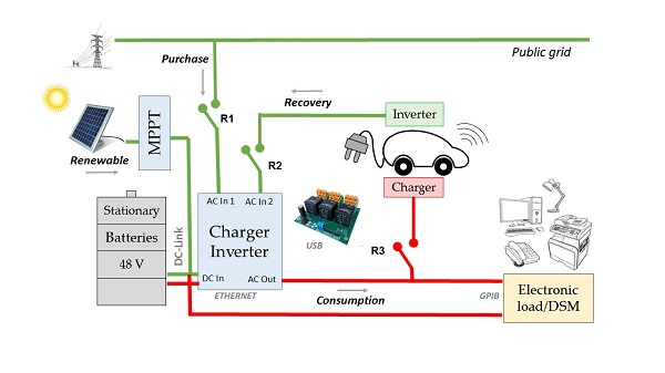
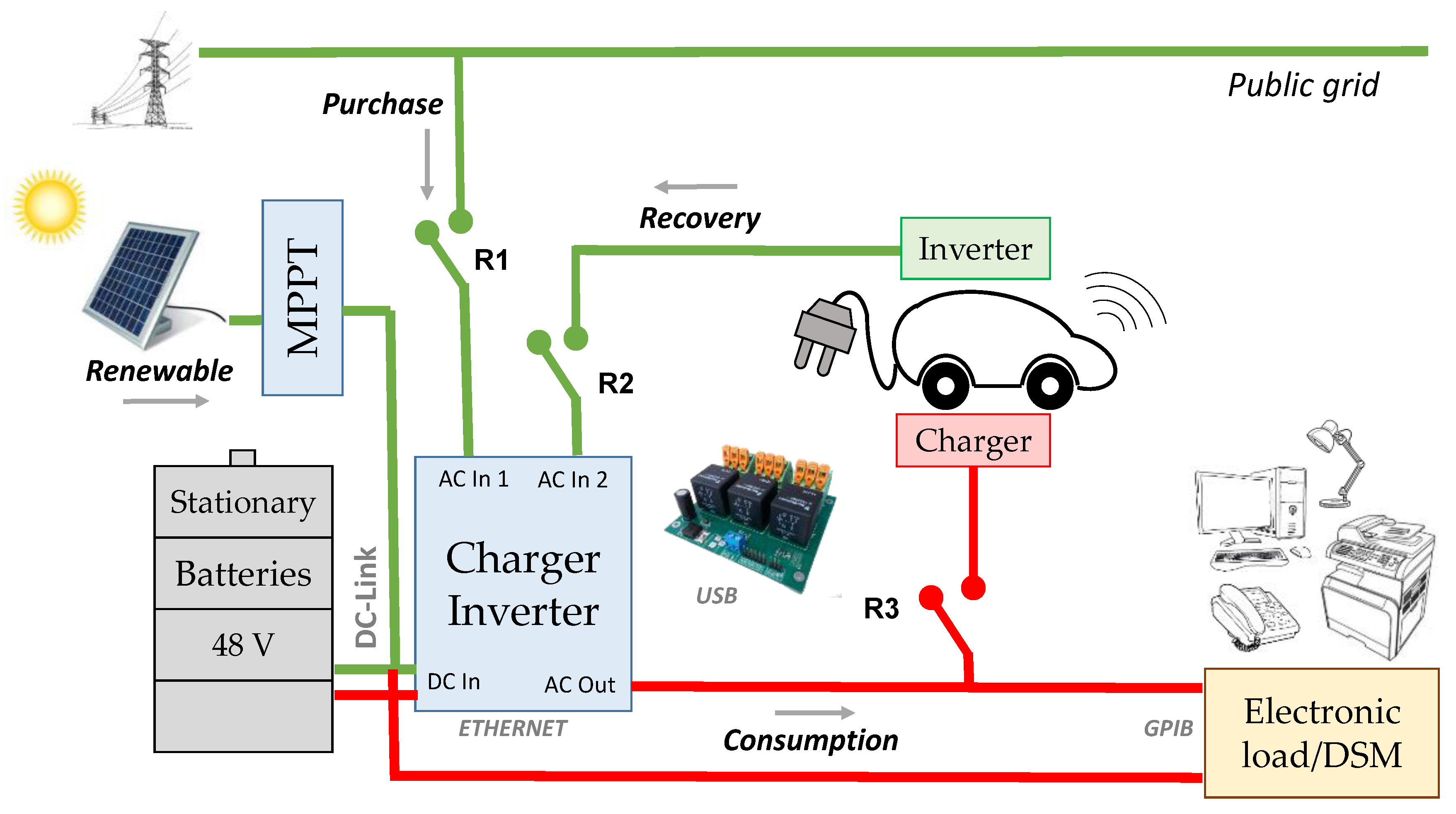
The smart micro-grids with PV systems that have appeared in previous works can adopt several configurations, such as grid-tied or off-grid [16], and with or without storage. In the present work, an office building with a PV-battery system and EV was considered. This configuration differs from a stand-alone installation, since it is not totally independent of the public grid. However, the power obtained from the public grid can be minimized, and partial disconnections from the public grid will be addressed. According to [5], a DC-Link layout is used, which means that the battery is connected before the DC/AC converter, as depicted in Figure 1. As can be seen, the input power is represented by means of green bonds, and belongs to the energy from the public grid, the solar panels, the electric vehicle, and the batteries. On the other hand, the red bonds represent the output power, which is the power that the charger/inverter employs in balancing the demand and charging the batteries.
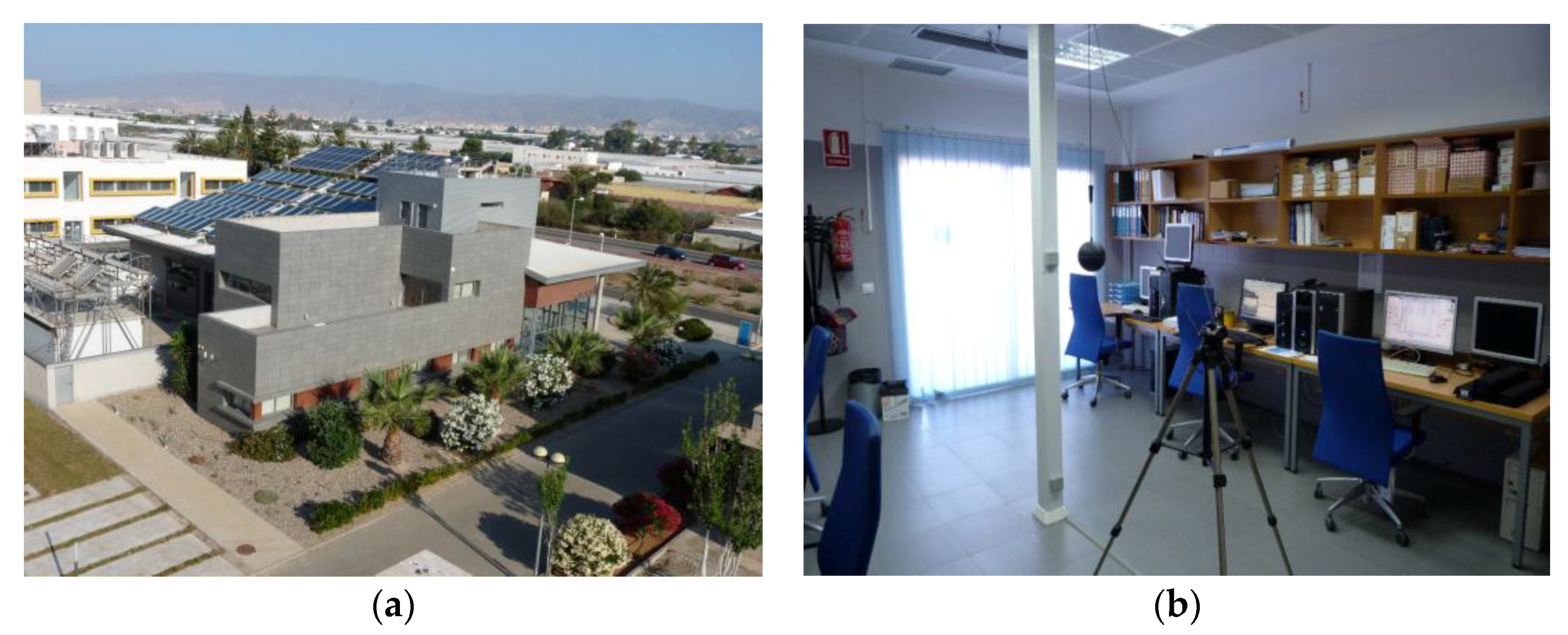
The analyzed case-study corresponded to a micro-grid integrated in the center for solar energy research (CIESOL) building, a bioclimatic building designed to research renewable energies (Figure 2a) located at the University of Almeria (Almeria, Spain) 36.83 N, 2.40 W. This placement, with an annual average sunshine duration of almost 3000 h, is very suitable for solar energy applications and the CIESOL building counts with both active solar heating and cooling [17]. In addition to on-going efforts in analyzing and characterizing the overall power consumption of the building [18,19], this work aimed to control and optimize the building parts power management by a conscious design and operation of micro-grids to be scaled-up to an integrated building scheme. To achieve this, first, a laboratory on the first floor of the building was selected (Figure 2b) as the reference case for operating a micro-grid consisting of a dedicated photovoltaic and storage facility where the EV was also considered as part of the proposed configuration. Hence, the energy demand corresponded to the use of computers, artificial lighting, and other laboratory instruments, and thanks to previous work, normalized profiles of the laboratory consumption were available [20].
The normalized electric load patterns, represented by the block electronic load/DSM in Figure 1, were reproduced by an electronic programmable load. This ensured the repeatability of the experiments, without interfering in the normal operation of the laboratory. The electronic load was connected to the output of the charger/inverter, which could be connected or disconnected from the public grid by means of a relay referred to as R1 in Figure 1. In parallel to the electronic load, another power line fed an EV charging station controlled by a second relay (R2 in Figure 1). Finally, another power line connected to the inverter’s second AC input enabled an EV to inject energy to the micro-grid when needed by acting on a third (R3 in Figure 1). More details about the micro-grid comprising the testbed are provided in Section 4.
The attached problem consists of minimizing electricity costs as a consequence of the energy consumed from the public grid in a normal working week. For this purpose, an energy management strategy was implemented. This strategy relies on a rule-based controller, which determines the state of the R1, R2, and R3 relays, depending on the criteria of PV production, instant consumption, the SOC of batteries, or the cost of electricity.
3. Methodology
3.1. A Low Scale Micro-Grid as Testbed
To analyze the attached problem, we designed a micro-grid including a solar power source, a stationary battery pack, and an electronic load (Figure 3a), as well as an electric vehicle (Figure 3b). The core of the micro-grid was a model Quattro charger/inverter manufactured by Victron Energy (Victron Energy, Almere Haven, The Netherlands), which can retrieve power from four different sources separately, and provide power by means of both a DC current, a DC, and an AC power bus. Henceforth, it will be referred to as input power when the charger/inverter is receiving energy, and output power when the charger/inverter is providing energy to the loads. Four solar panels (model REC260 PE) with a nominal power of 260 Wp were used. Two pairs of series-connected panels in parallel fed the maximum power point tracker (MPPT) (model 85/150, Victron Energy, Almere Haven, The Netherlands). The output of the MPPT controller addressed a DC bus connecting a pack of batteries, a DC electronic load, and the charger/inverter. The battery pack was the model B-Box 5.0 of the Build Your Dreams (BYD) manufacturer (BYD, Shenzhen, China), which can deliver up to 5 kW with a capacity of 4.90 kWh. The AC electronic load was a Chroma model 63800, with a maximum power of 4.5 kW. The charger/inverter provided an AC power bus that both the electric vehicle and the AC electronic load were connected to. The electric vehicle featured a 4.8 kW DC motor, and was powered by a pack of eight batteries (model 6V-GEL, Trojan Battery Company, Santa Fe Springs, CA, USA). This vehicle is used for research purposes, and more information about its characteristics is provided in [21].
A key idea of this work consisted of ensuring the repeatability and automatization of the controllable variables affecting the experiments. Consumption data were collected to find a typical pattern of demand that could be easily reproduced by the electronic load. Under this scenario, how an accurate energy management strategy can minimize the amount of energy provided by the public grid can be studied. For this purpose, a rule-based controller was designed, which determined the state of three binary variables. The first variable is related to the first relay, which allows—or not—taking energy from the public grid. The second variable enables the recovery energy from the vehicle by means of another relay. Finally, the vehicle starts re-charging whenever the last of the three binary variables is on, by means of the third relay. The control law determines how long each of the three relays is closed and the hour of the day at which this occurs.
Regarding communications, the different elements of the micro-grid were interconnected as follows: First, the solar charger, the batteries, and the charger/inverter communicated by means of a proprietary bus and a control unit, which published the dataset to a private web. For this specific purpose it was not necessary to install any sensor or develop supervisory control and data acquisition (SCADA) like that proposed in [22]. Among all the reported data, the developed control algorithm selected those related to the available and demanded power as well as the stationary batteries SOC. For this purpose, the main function was called a json library, which was able to log-in and retrieve the data provided by the control unit. Besides these components, a personal computer (PC) was in charge of managing the electronic load by means of a General Purpose Interface Bus (GPIB). This computer also performed the DSM tasks and communicated with the computer running the main control loop by means of a local server using the Transmission Control Protocol/ Internet Protocol (TCP/IP). In addition, this computer was responsible for taking the control actions via USB signals to a specific purpose board of relays. As another important agent, the electric vehicle must be interconnected with the control loop. For this purpose, Secure Shell (SSH) communications were established with a local server thanks to the campus wireless network. In this way, the control loop was able to obtain the vehicle’s SOC and the distance travelled at each time step, among other variables.
3.2. Power Balance Formulation
As mentioned before, the proposed control strategy aimed to efficiently manage the energy exchanges between the elements of the micro-grid under study. For this purpose, the selected strategy must accomplish the instantaneous power balance at each time step [23]. Mathematically, it can be expressed that the sum of the power from the different sources must be equal to the output power:
where Pgrid_i represents the power consumed from the public grid at time I, PPV_i is the power produced by the solar panels; Pstat_i the power from the stationary batteries; PEV_i is the power from the batteries of the electric vehicle; Cload_i is the power demanded in the laboratory; Cstat_i is the charging power of the stationary batteries; CEV_i is the charging power of the electric vehicle; and Cfeed_i is the feed-in power. Note that R1, R2, and R3 are binary variables that represent the state of the relays 1, 2, and 3, respectively. Their value is 1 when the relays are closed, and 0 otherwise.
Maximum power from the public grid: The power consumed from the grid is limited to a maximum value (Pgrid_max) when relay R1 is closed. Otherwise, there is no consumption from the public grid:
Maximum power exchange between the electric vehicle and the micro-grid: The power consumed from the electric vehicle in mode V2G (PEV_i) when R2 is closed is limited to a maximum value PEV_max. Similarly, the charging power (CEV_i) must be equal to or less than a threshold value CEV_max when R3 is closed.
Maximum discharge and charge power of the stationary batteries: The power provided by the batteries must be equal to or less than the threshold value Pstat_max. Similarly, the maximum power for charging the stationary batteries must be equal to or less than Cstat_max:
States of Charge: The state of charge of the stationary batteries (SOCstat_i) and the electric vehicle’s batteries (SOCEV_i) must be between certain limits:
Incompatibilities: The first of the next two equations ensures that there is no consumption from the public grid and electric vehicle simultaneously, and the second that the vehicle is not charging and discharging at the same time:
The proposed rule-based control system described in the next section was able to ensure the power balance accomplishing all these constraints, leading to a solution across the control horizon that, although not guaranteed to be optimal, addressed a good performance.
3.3. Rule-Based Controller
The problem under study is characterized by the use of equipment for the exchange of power between the micro-grid and both the stationary and electric vehicle batteries without the ability to regulate in real time the amount of energy to be received or delivered by each battery. Instead, these values, as in the majority found in the market, can be set to a fixed parameter with the use of manual switches, or in some cases, firmware programmers. Then, the control action is defined by the binary variables R1, R2, and R3, corresponding to the relays mentioned in previous sections, in contrast with other kinds of controllers as the used in, where the power flows from the batteries and the micro-grid are treated as continuous variables, and hence in practice, more sophisticated and complex power converters should be used.
The proposed algorithm, which involves the power balance problem described in Section 3.2 and characterized by Equations (1)–(10), is represented by Figure 4. This algorithm was implemented in a MATLAB script that collected all available data at every time step about the power produced or demanded by each component as well as the state of charge of the batteries. Given the low rate of change of these last variables, the step size of the control algorithm was 60 s. At the same time, this step size ensured the power balance and battery preservation, even considering that the electric vehicle may unexpectedly depart from the micro-grid. Depending on whether there was an excess of solar energy, the following sequence of stages may occur:
The first case leads to Stage 1 (as labeled in Figure 4), where the excess of solar energy was first used to charge the stationary batteries, as long as its SOC remained as per Equation (7). This power flow was limited by the parameter Cstat_max, according to Equation (6), whose value was set for the charger/inverter to not damage the batteries. After that, in Stage 2, a similar process occurred for the electric vehicle. The remaining power after charging the stationary batteries, if available, may be used to charge the electric vehicle batteries by closing R3 when its SOC is below SOCEV_max (Equation (8)), at a maximum power of CEV_max, according to Equation (4). The remaining power, when available, is used as feed-in power (C_feed). In all stages of this case, the relays R1 and R2 were open.
The second case, which occurred when there was not an excess of solar energy, led to Stage 1′. At this stage, the needed power was provided by the stationary batteries if the SOC was above SOCstat_min, in accordance Equation (7), and at a maximum power of Pstat_max (Equation (5)). If the power demand could not be provided completely by the stationary batteries because it was greater than Pstat_max, or the SOC was not above SOCstat_min, it would be attempted to balance it at Stage 2′, following the same criteria. Hence, if the demanded power was lower than PEV_max (Equation (3)) and the SOC of the electric vehicle batteries was above SOCEV_min (Equation (8)), relay R2 closed to enable energy recovery from the electric vehicle. Finally, in Stage 3′, if there was not enough power to satisfy the demand after considering the contribution of the solar panels, the stationary batteries and the electric vehicle, R1 closed to obtain power from the public grid, up to the maximum value Pgrid_max imposed by Equation (2). In addition, R2 opened according to Equation (9), since it is preferable to charge the vehicle at night. In all stages of this case, relay R3 was open. It is worth pointing out that, on the one hand, the exchange of power between the electric vehicle may only occur during working hours. This is controlled by a variable (is EV in the flowchart) that determines whether the electric vehicle is plugged in or not. On the other hand, the value of SOCEV_min has to be high enough to enable, at least, a return trip.
4. Experimental Results
4.1. First Experiment: Monitorization of One Working Day
This experiment consisted of monitoring the power flows which took place in the micro-grid for an ordinary operation day in autumn. The experiment started at midnight, with both the electric vehicle and the stationary batteries fully charged. The load profile belonged to the typical demands of a small office. Hence, the demand was low at night, and reached its maximum during the working hours. Regarding the electric vehicle, a round trip was performed during the day. The first one occurred at 7:30 a.m., with a distance of 20 km. The second trip was performed at 19:30 p.m., with the same distance. The evolution of power flows and state of charge of the batteries is depicted in Figure 5.
As can be seen, the stationary batteries provided energy for the nocturnal consumption of the supervisory devices. Between 7:30 and 8:00 a.m., as the electric vehicle arrived, their batteries depleted until the vehicle was parked and connected to the micro-grid. At this moment, no power exchange between the vehicle and the micro-grid was required, so relays R2 and R3 remained open. Once the activity in the laboratory started, the load increased up to 800 W. This power was delivered by the stationary batteries and, at a low level, by the PV panels. From 10:00 a.m., the solar energy reached its greatest potential. This energy itself was able to satisfy the electricity demand for some period of time. The stationary battery SOC was close to its minimum and started recharging when the solar energy exceeded the load. At 1:30 p.m., when the load decreased drastically, this recharging power reached 600 W, allowing their SOC to increase to 70%. However, this value drastically decreased again at 5:00 p.m. due to the restart of laboratory activity and the absence of solar energy. Once the workday ended, the electric vehicle started the return trip, while its SOC decreased to 72%. At the end of the day, the stationary batteries were nearly depleted.
It is worth pointing out that the pattern of solar energy production and consumption may be reproduced for a typical working week due to the atmospheric stability in Almeria, and the repetitive tasks carried out in the laboratory [20]. Next, experiments were conducted following these assumptions.
4.2. Second Experiment: Energy Management for a Working Week
Taking into account the data obtained in the first experiment, the proposed energy management strategy was tested under several scenarios by means of simulation.
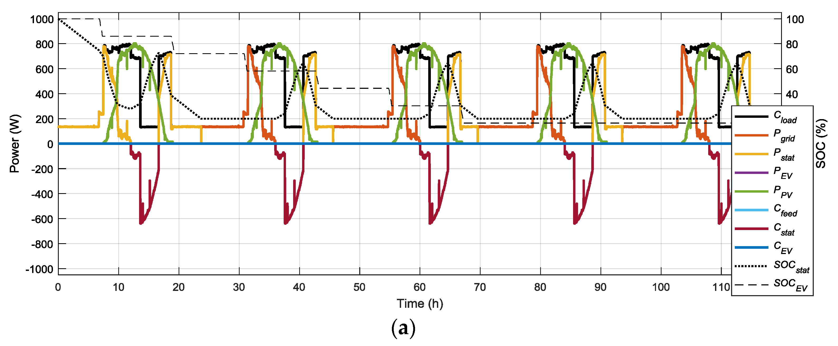
Scenario 1: The stationary and vehicle’s batteries are uniquely recharged by solar energy, and V2G option is not allowed.
This scenario is the same that was used for the one-day test. Hence, at the end of the first day, the stationary batteries were depleted, and relay R1 was switched to enable consumption from the public grid. The total amount of energy from the grid at the end of the week (Egrid) was 11,725 Wh. On the other hand, the electric vehicle could perform only three round trips given that recharge from the grid was not allowed. Results of this experiment are shown in Figure 6a.
Scenario 2: Stationary batteries are uniquely recharged by solar energy, and the V2G option is allowed as well as charging the electric vehicle at night.
Under these conditions, an important decrease of the energy consumed from the public grid in the laboratory was addressed, due to the V2G option. However, the energy consumed at home must also be considered. Since the electric vehicle could be recharged at home, it could deliver energy when the stationary batteries and PV energy together were not enough to cover the demand in the laboratory. Despite the losses at the charging and discharging of batteries, this option may be profitable if the costs of electricity at night are much lower than during the day. Since the electric vehicle is charged on the second and fourth nights, it can perform the five round trips. At the end of the working week, its SOC was 46%, while the stationary batteries were depleted. Results of this experiment are shown in Figure 6b.
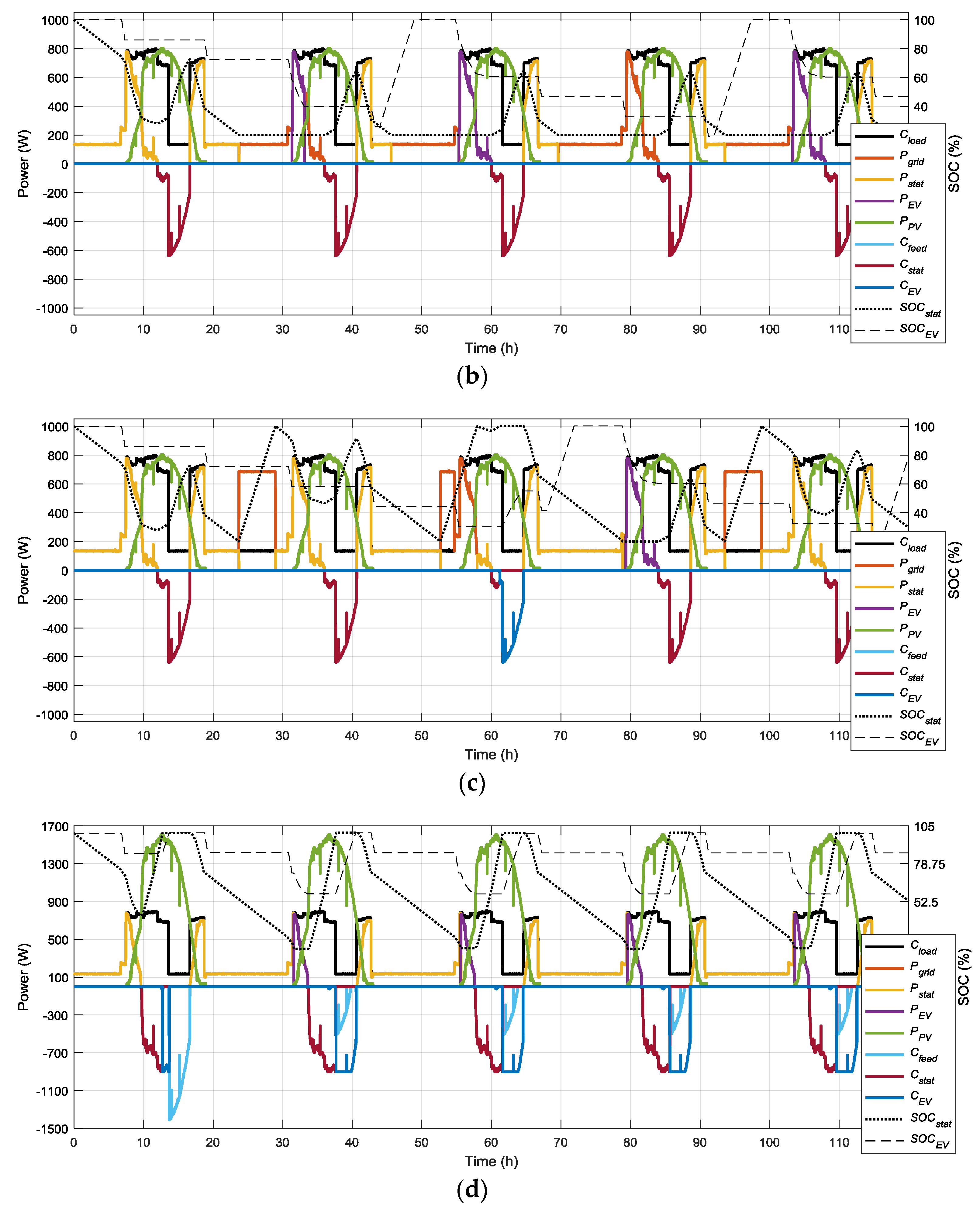
Scenario 3: Stationary batteries and electric vehicle can be charged from the public grid at night, as well as the V2G option.
Under these conditions, the amount of energy consumed at home for charging the electric vehicle (EEV) was reduced. This was due to the apparition of periods where the stationary batteries were fully charged and there was an excess of solar energy that could be used to charge the vehicle’s batteries. The consumption from the public grid in the laboratory increased, but this consumption was addressed at night, with the possible profits mentioned before. The stationary and electric vehicle states of charge at the end of the working week were 26% and 79%, respectively. Results of this experiment are shown in Figure 6c.
Scenario 4: Another array of PV panels is installed, allowing the stationary batteries and electric vehicle to be charged from the public grid at night, as well as the V2G option.
The nominal power of the PV system increased from 1 kWp to 2 kWp, which enabled the micro-grid to operate without taking energy from the public grid. At the end of the working week, the stationary and electric vehicle states of charge were 53% and 86%, respectively. These levels were high enough to start a new cycle under similar conditions. An economic study of the economic impact of the investment considered in this scenario was beyond the scope of this paper. However, methodologies to study this kind of investments are provided in [24]. Results of this experiment are shown in Figure 6d. In Table 1, the results of the different scenarios considered in this experiment are summarized.
5. Conclusions
In this paper, a novel strategy was proposed for the energy management of micro-grids with PV-battery systems and electric vehicles. This strategy implemented a rule-based controller aimed at reducing the consumption of electricity from the public grid for a given load, with a sample time of 60 s and ensuring power balance at each time step. As a testbed, it considered the load demanded by a laboratory during standard working days. By means of a set of three relays, the controller could establish priorities between the use of different sources. Thus, the PV energy was used first. Next, the stationary batteries provided the necessary energy when the solar energy itself was not enough to satisfy the demand. In cases when the demand was greater than the sum of the photovoltaic and stationary batteries energy, the electric vehicle may act as an extra source, referred to as V2G. Finally, as a last option, energy from the public grid was consumed. On the other hand, stationary batteries were first charged in cases of excess PV energy, and the electric vehicle was a second choice. According to the framework of this study, feed-in energy was the least desirable option. Through experimental data and simulations, we demonstrated the suitability of the proposed strategy for efficient management of these kinds of systems. This methodology can be easily adjusted to larger-scale grids, as the entire office building integrating the laboratory under study. The application to other smart-grids, with several electric cars addressing different trips, and the application of different kinds of controllers arise as future work.
Acknowledgments
This work was funded by the National R+D+i Plan Projects DPI2014-56364-C2-1-R and DPI2017-85007-R of the Spanish Ministry of Economy, Industry, and Competitiveness and ERDF funds.
Author Contributions
Jose Luis Torres-Moreno designed the methodology. Francisco Rodriguez built the testbed. Antonio Gimenez-Fernandez conducted the experiments. Manuel Perez-Garcia analyzed the results. Jose Luis Torres-Moreno and Antonio Gimenez-Fernandez wrote the paper.
Conflicts of Interest
The authors declare no conflict of interest.
References
- Gray, M.K.; Morsi, W.G. On the role of prosumers owning rooftop solar photovoltaic in reducing the impact on transformer’s aging due to plug-in electric vehicles charging. Electr. Power Syst. Res. 2017, 143, 563–572. [Google Scholar] [CrossRef]
- Luthander, R.; Widén, J.; Nilsson, D.; Palm, J. Photovoltaic self-consumption in buildings: A review. Appl. Energy 2015, 142, 80–94. [Google Scholar] [CrossRef]
- Quoilin, S.; Kavvadias, K.; Mercier, A.; Pappone, I.; Zucker, A. Quantifying self-consumption linked to solar home battery systems: Statistical analysis and economic assessment. Appl. Energy 2016, 182, 58–67. [Google Scholar] [CrossRef]
- Weniger, J.; Tjaden, T.; Quaschning, V. Sizing of residential PV battery systems. Energy Procedia 2014, 46, 78–87. [Google Scholar] [CrossRef]
- Riesen, Y.; Ballif, C.; Wyrsch, N. Control algorithm for a residential photovoltaic system with storage. Appl. Energy 2017, 202, 78–87. [Google Scholar] [CrossRef]
- Solano, J.C.; Olivieri, L.; Caamaño-Martín, E. Assessing the potential of PV hybrid systems to cover HVAC loads in a grid-connected residential building through intelligent control. Appl. Energy 2017, 206, 249–266. [Google Scholar] [CrossRef]
- Castillo-Cagigal, M.; Caamaño-Martín, E.; Matallanas, E.; Masa-Bote, D.; Gutiérrez, A.; Monasterio-Huelin, F.; Jiménez-Leube, J. PV self-consumption optimization with storage and Active DSM for the residential sector. Sol. Energy 2011, 85, 2338–2348. [Google Scholar] [CrossRef] [Green Version]
- Lorenzi, G.; Silva, C.A.S. Comparing demand response and battery storage to optimize self-consumption in PV systems. Appl. Energy 2016, 180, 524–535. [Google Scholar] [CrossRef]
- Martín-Chivelet, N.; Montero-Gómez, D. Optimizing photovoltaic self-consumption in office buildings. Energy Build. 2017, 150, 71–80. [Google Scholar] [CrossRef]
- Van der Kam, M.; van Sark, W. Smart charging of electric vehicles with photovoltaic power and vehicle-to-grid technology in a microgrid; a case study. Appl. Energy 2015, 152, 20–30. [Google Scholar] [CrossRef]
- Colmenar-Santos, A.; de Palacio-Rodriguez, C.; Rosales-Asensio, E.; Borge-Diez, D. Estimating the benefits of vehicle-to-home in islands: The case of the Canary Islands. Energy 2017, 134, 311–322. [Google Scholar] [CrossRef]
- Wu, X.; Hu, X.; Teng, Y.; Qian, S.; Cheng, R. Optimal integration of a hybrid solar-battery power source into smart home nanogrid with plug-in electric vehicle. J. Power Sources 2017, 363, 277–283. [Google Scholar] [CrossRef]
- Khoucha, F.; Benbouzid, M.; Amirat, Y.; Kheloui, A. Integrated Energy Management of a Plug-in Electric Vehicle in Residential Distribution Systems with Renewables. In Proceedings of the 2015 IEEE 24th International Symposium on Industrial Electronics (ISIE), Buzios, Brazil, 3–5 June 2015; IEEE: Piscataway, NJ, USA, 2015; pp. 775–780. [Google Scholar]
- Munkhammar, J.; Grahn, P.; Widén, J. Quantifying self-consumption of on-site photovoltaic power generation in households with electric vehicle home charging. Sol. Energy 2013, 97, 208–216. [Google Scholar] [CrossRef]
- Kanwar, A.; Rodríguez, D.I.H.; Appen, J.V.; Braun, M. A Comparative Study of Optimization- and Rule-Based Control for Microgrid Operation. In Proceedings of the Power and Energy Student Summit, Dortmund, Germany, 13–14 January 2015; pp. 1–6. [Google Scholar]
- Ogunjuyigbe, A.S.O.; Ayodele, T.R.; Monyei, C.G. An intelligent load manager for PV powered off-grid residential houses. Energy Sustain. Dev. 2015, 26, 34–42. [Google Scholar] [CrossRef]
- Rosiek, S.; Batlles, F.J. Renewable energy solutions for building cooling, heating and power system installed in an institutional building: Case study in southern Spain. Renew. Sustain. Energy Rev. 2013, 26, 147–168. [Google Scholar] [CrossRef]
- Khosravani, H.R.; Del, M.; Castilla, M.; Berenguel, M.; Ruano, A.E.; Ferreira, P.M. A Comparison of Energy Consumption Prediction Models Based on Neural Networks of a Bioclimatic Building. Energies 2016, 9, 57. [Google Scholar] [CrossRef]
- Mena, R.; Rodríguez, F.; Castilla, M.; Arahal, M.R. A prediction model based on neural networks for the energy consumption of a bioclimatic building. Energy Build. 2014, 82, 142–155. [Google Scholar] [CrossRef]
- Alamin, Y.I.; Castilla, M.; Alvarez, J.D.; Ruano, A.E.; Perez, M. Mathematical modelling of the electric load profile of a low energy laboratory building in Spain. In Proceedings of the 11th ISES EuroSun Conference on Sorlar Energy for Bulidings and Industry, Palma, Spanish, 11–14 October 2016; pp. 11–14. [Google Scholar]
- Torres-Moreno, J.-L.; Blanco, J.-L.; Bellone, M.; Rodriguez, F.; Gimenez-Fernandez, A.; Reina, G. A proposed software framework aimed at energy-efficient autonomous driving of electric vehicles. In Lecture Notes in Artificial Intelligence, Proceedings of the International Conference on Simulation, Modelling, and Programming for Autonomous Robots (SIMPAR 2014), Bergamo, Italy, 20–23 October 2014; Springer: Berlin, Germany, 2014; Volume 8810. [Google Scholar]
- Moreno-Garcia, I.; Palacios-Garcia, E.; Pallares-Lopez, V.; Santiago, I.; Gonzalez-Redondo, M.; Varo-Martinez, M.; Real-Calvo, R. Real-Time Monitoring System for a Utility-Scale Photovoltaic Power Plant. Sensors 2016, 16, 770. [Google Scholar] [CrossRef] [PubMed]
- Zerkaoui, S.; Hajjaji, A.E.L.; Bosche, J. On-line Control Strategy for Instantaneous Power Management of Hybrid Power System Based on Dynamic Fuzzy Logic Controller. In Proceedings of the 2012 7th IEEE Conference on Industrial Electronics and Applications (ICIEA), Singapore, 18–20 July 2011; pp. 1130–1136. [Google Scholar]
- Hoppmann, J.; Volland, J.; Schmidt, T.S.; Hoffmann, V.H. The economic viability of battery storage for residential solar photovoltaic systems—A review and a simulation model. Renew. Sustain. Energy Rev. 2014, 39, 1101–1118. [Google Scholar] [CrossRef]
Figure 1.
The micro-grid under study, comprising a photovoltaic system with storage, an electric vehicle, and a Demand-Side Management (DSM) system reproduced by a programmable electronic load. In the middle, a relay board controls R1, R2, and R3.
Figure 1.
The micro-grid under study, comprising a photovoltaic system with storage, an electric vehicle, and a Demand-Side Management (DSM) system reproduced by a programmable electronic load. In the middle, a relay board controls R1, R2, and R3.

Figure 2.
Center for solar energy research (CIESOL) building (a) and the laboratory under study (b).
Figure 2.
Center for solar energy research (CIESOL) building (a) and the laboratory under study (b).

Figure 3.
Experimental testbed. (a) PV-Battery system and electronic loads. (b) Electric vehicle.
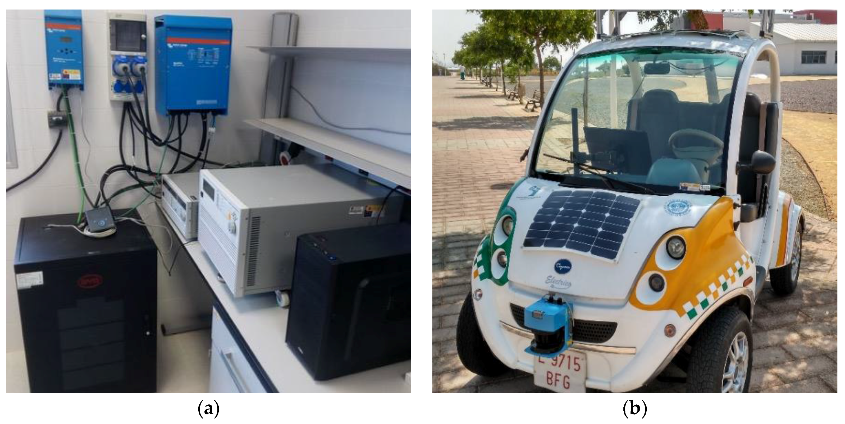
Figure 4.
Control algorithm flowchart.

Figure 5.
Power flows and batteries’ SOC for one day.
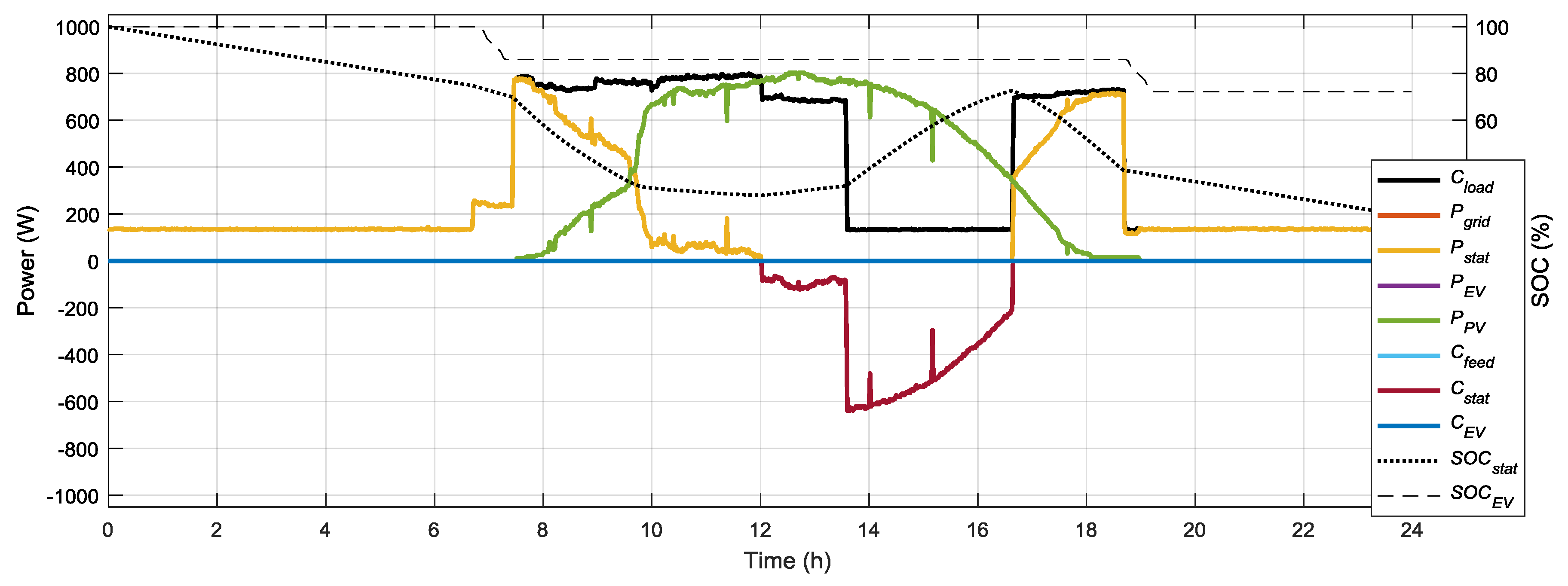
Figure 6.
Power flows and batteries’ SOC for five days. (a) Only solar charge of batteries. (b) EV batteries charge from grid and V2G allowed. (c) Stationary and EV battery charge from grid and V2G allowed. (d) Double solar power installed.
Figure 6.
Power flows and batteries’ SOC for five days. (a) Only solar charge of batteries. (b) EV batteries charge from grid and V2G allowed. (c) Stationary and EV battery charge from grid and V2G allowed. (d) Double solar power installed.


Table 1.
Summary of the results of experiment 2 for each scenario.
| Scenario | Egird (kWh) | EEV (kWh) | Round Trips | Final SOCstat (%) | Final SOCEV (%) |
|---|---|---|---|---|---|
| 1 | 11.724 | 0 | 3 | 20 | 16 |
| 2 | 7.556 | 9.315 | 5 | 20 | 47 |
| 3 | 10.223 | 7.133 | 5 | 26 | 79 |
| 4 | 0 | 0 | 5 | 53 | 86 |
© 2018 by the authors. Licensee MDPI, Basel, Switzerland. This article is an open access article distributed under the terms and conditions of the Creative Commons Attribution (CC BY) license (http://creativecommons.org/licenses/by/4.0/).
Share and Cite
MDPI and ACS Style
Torres-Moreno, J.L.; Gimenez-Fernandez, A.; Perez-Garcia, M.; Rodriguez, F. Energy Management Strategy for Micro-Grids with PV-Battery Systems and Electric Vehicles. Energies 2018, 11, 522. https://doi.org/10.3390/en11030522
AMA Style
Torres-Moreno JL, Gimenez-Fernandez A, Perez-Garcia M, Rodriguez F. Energy Management Strategy for Micro-Grids with PV-Battery Systems and Electric Vehicles. Energies. 2018; 11(3):522. https://doi.org/10.3390/en11030522
Chicago/Turabian StyleTorres-Moreno, Jose Luis, Antonio Gimenez-Fernandez, Manuel Perez-Garcia, and Francisco Rodriguez. 2018. "Energy Management Strategy for Micro-Grids with PV-Battery Systems and Electric Vehicles" Energies 11, no. 3: 522. https://doi.org/10.3390/en11030522
Note that from the first issue of 2016, this journal uses article numbers instead of page numbers. See further details here.