Dynamic Wireless Power Transfer for Logistic Robots
by
 , , and
Marojahan Tampubolon
1 ,
,
Laskar Pamungkas
1,
Huang-Jen Chiu
1,*, 
Yu-Chen Liu
2 and
Yao-Ching Hsieh
3 1
Department of Electronic and Computer Engineering, National Taiwan University of Science and Technology, Taipei 10607, Taiwan
2
Department of Electrical Engineering, National I-lan University, Yilan 206, Taiwan
3
Department of Electrical Engineering, National Sun Yat-Sen University, Kaohsiung 80424, Taiwan
*
Author to whom correspondence should be addressed.
Energies 2018, 11(3), 527; https://doi.org/10.3390/en11030527
Submission received: 16 January 2018
/
Revised: 26 February 2018
/
Accepted: 27 February 2018
/
Published: 28 February 2018
(This article belongs to the Special Issue Power Electronics in DC-Microgrid Systems)
Abstract
:The prospect of using robots in warehouses or supply chain processes is increasing due to the growth of the online retail market. This logistic robot is available in the market and uses a battery as energy storage device. However, this battery is large and heavy. Therefore, it needs a long recharging time. Dynamic Wireless Power Transfer (DWPT) can be an alternative to the conventional charging system because of its safety and flexibility that enables in motion charging. DWPT reduces the battery requirement size and capacity. Hence the stored energy can be used effectively for load transportation. A compensation with an inductor and two capacitors in the transmitter side, and a series connected capacitor in the receiver side which is named LCC-S compensation type has the capability to maintain the transmitter current with a fixed frequency operation. It provides less variation of the output voltage in response to the load variation. Moreover, the compensation of the receiver side uses only a single series capacitor which is low-cost. The analysis, modeling, and design procedures are discussed in this paper as well as the hardware implementation and verification of a 1.5 kW maximum power DWPT. The experiment shows the capability of the proposed system and shows maximum efficiency can reach 91.02%.
1. Introduction
Information technology has shaped the form of the market in this recent years. The conventional market has been changing progressively in the online market. According to the prediction of Forrester Research cited in a DHL report, online retail in Europe grows by 10% year-on-year. China market will be equal to the combined market of France, Germany, Japan, the United Kingdom, and the United States by 2020 [1]. Logistic robots represent an emerging trend in online retail or supply chain companies because they can work more efficiently, effectively, and accurately. A logistic robot should be autonomous and able to replace humans in several parts of the process, such as the selection, packing, and delivery of the products. According to a report published by Bloomberg [2]. Amazon has approximately 30,000 Kiva robots in its warehouses across the globe which will be increasing in the future. A logistic robot should be flexible such that it is not powered by a wired power supply but using a rechargeable energy storage device. The amount of stored energy in a battery is proportional to the size and the weight of the battery. Besides the larger size and heavier weight, to have more stored energy lead to a longer operational hour and charging time. As a case, LocusBots [3] has an unloaded weight of 36 kg and a maximum payload of 46 kg. Thus, this robot uses its energy approximately 45% of its energy to carry its body, which could be a drawback. However, using a smaller battery also lead to a frequent recharging process which is inconvenient for the user.
Wireless power transfer (WPT) can be a solution to the previously mentioned problems because it is flexible, safe, and free of dust/dirt, and enables in motion charging system [4,5,6]. It should be noted that this benefit can be obtained if the system has been conformed to the existed regulation such IEEE Std C95.1™-2005 for safety level. More comprehensive study about the Electromagnetic Compatibility (EMC) and shielding method for WPT have been published in [7,8]. The WPT technology has very wide applications such as for Medical Implants [9,10], Unmanned Aerial Vehicles (AUV) [11,12], and transportation system like Tram [13]. The in-motion-charging feature enables the use of a small battery, which is lightweight without causing anxiety about running out of power, and frequent docking. The in-motion charging system in which the charging process is in progress while the receiver is moving is only possible if the Dynamic Wireless Power Transfer (DWPT) is applied. However, DWPT is subjected to the variation of the load and the coupling coefficient. Thus, the charging system should be able to respond robustly to these variations. Some developments in DWPT have been published in the recent years. In [14,15] the authors focused on the control method of the DWPT and used the Series-Series (SS) compensation in their studies. The SS compensation has a simple topology, an independent load, and against frequency. However, as discussed in [16], the independent coupling coefficient frequency only available for symmetric compensator in which the resonant condition of the transmitter and receiver is similar and at a certain value of the load. In another word, the frequency cannot be maintained constant for various coupling coefficient and load. By contrast, another type of compensator that consists an inductor, two capacitors in the transmitter side, and a series connected capacitor in the receiver side which is named the LCC-S or LCC-C compensation topology provides a constant transmitter coil current, and a robust power characteristic against coupling coefficient variation if the design is optimized [17]. This characteristic makes LCC-S compensation suitable for DWPT.
This study extends the application of the LCC-S compensated DWPT for a logistic robot that requires a smaller and lighter receiver part. The contribution of this includes the study of the LCC-S topology with a segmented lumped coil which is more practical for DWPT compared to a single symmetric coil as studied in [17]. This proposed topology has less sensitivity to load variation, and more predictable behavior against the mutual coupling variation. The independent load transmitter coils current characteristic also can limit the maximum voltage stress of the compensator capacitor. In addition to the contribution, the presented analysis, practical design guideline may be useful for the implementation of the system in near future. We also expect that this study could encourage the idea of using DWPT for logistic robot application that could be a promising technology in this decade. In the subsequent sections, the analysis, modeling, design, hardware implementation, and testing procedures will be discussed.
2. Analysis and Characteristic of LCC-S DWPT
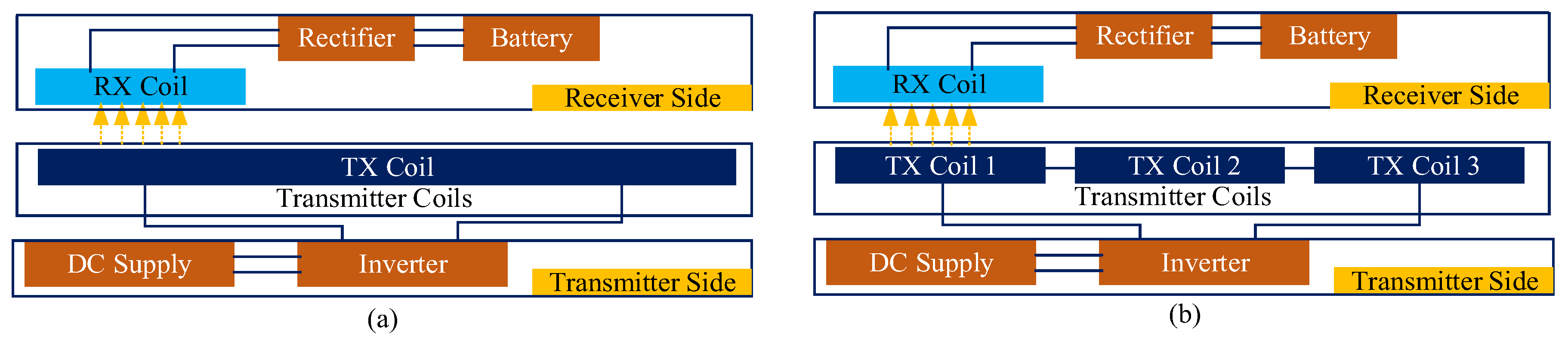
A complete system of a DWPT consists of AC-DC converter, inverter, resonant compensation circuit of the primary and secondary side, transmitter and receiver coil, rectifier, and post-regulator stage if needed. The AC-DC converter is necessary to convert the AC voltage from the utility AC grid to the DWPT system to serve as the power factor corrector (PFC). The inverter provides the square AC voltage to the compensation circuit and again reconverted to DC voltage by the rectifier, and in some cases, it is connected to the post regulator converter. Figure 1 illustrates two types of transmitter coil configuration. It can be either a long single track, as depictured in Figure 1a, or a segmented lumped coil, as depictured in Figure 1b. The utilization of a long single track transmitter has been reported in [18] under a platform called Roadway Powered Electric Vehicle (RPEV).
This configuration has a more robust coupling coefficient variation, but it suffers from the small coupling and stray magnetic field. In contrary, the segmented lumped coils suffer from the coupling variation, such that system has to be optimized to have the robust power transfer against the coupling coefficient. In this study, a segmented lumped transmitter is selected and optimization is implemented by optimizing the compensator design.
The analysis in this section only focuses on the DC-DC stage. Therefore, the output of AC-DC voltage is represented as the DC input voltage (Vin(DC)). Figure 2 shows that compensator consists of a series resonant inductor (Lpr), a parallel resonant capacitor (Cpp), a series capacitor in the transmitter (Cps), and a series capacitor in the receiver side (Css). This is why it’s named as the LCC-S or LCC-C DWPT. A segmented three lumped coils can be considered as a transmitter inductor (Lp) as expressed in (1). Mutual inductance (M) between the transmitter and receiver is expressed in (2), wherein k is the coupling coefficient. In this section, the analysis of the system is based on the AC analysis by means first harmonic approximation (FHA). We also have presented this analysis for a static WTP system in [19]. In this method, only the fundamental frequency is considered [10]. All of the components are assumed ideal for simplicity.
Based on the FHA, the square wave inverter voltage can be expressed as (3) followed by its magnitude r.m.s value in (4). The output AC voltage and equivalent AC load also can be converted from the output DC voltage and DC load as expressed in (5) and (6) respectively. From (4) and (5) we know that the magnitude gain of the DC-DC stage voltage is equal to the magnitude gain of compensator circuit. Therefore, the behavior of the system can be analyzed by analyzing the compensator circuit.
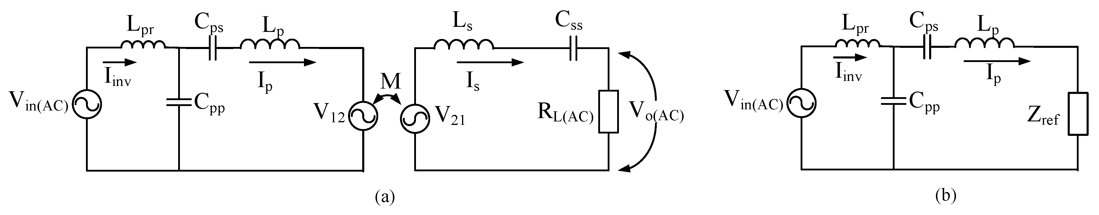
An AC equivalent circuit of the compensator parameter is depicted in Figure 3a. As expressed in (1), the transmitter inductor can be modeled as a single inductor by assuming that the coupling coefficient between each lumped coil of the transmitter can be ignored. The circulating current in the transmitter induces the magnetic field to the receiver coil and vice versa that generates the induced voltage at both side coils as expressed in (7). Equation (8) expresses the impedance of the receiver side (Zs) which can be reflected to the transmitter side as Zref as shown in (9). By doing so, the circuit can be simplified as illustrated in Figure 3b.
The current of the primary coil can be obtained by applying Kirchhoff’s law as shown in (10). Since the inverter current (Iinv) is the total current flow through Cpp (ICpp) and transmitter (Ip), (10) can be modified become (11). If the switching frequency is equal to then (12) is valid and the impedance of the LC resonant can be eliminated. Thus, the relationship between the primary current and the AC input voltage is written in (13). It shows that the primary coil current (Ip) is independent of load variation and can be maintained constant by maintaining the inverter output voltage and the switching frequency constant [20].
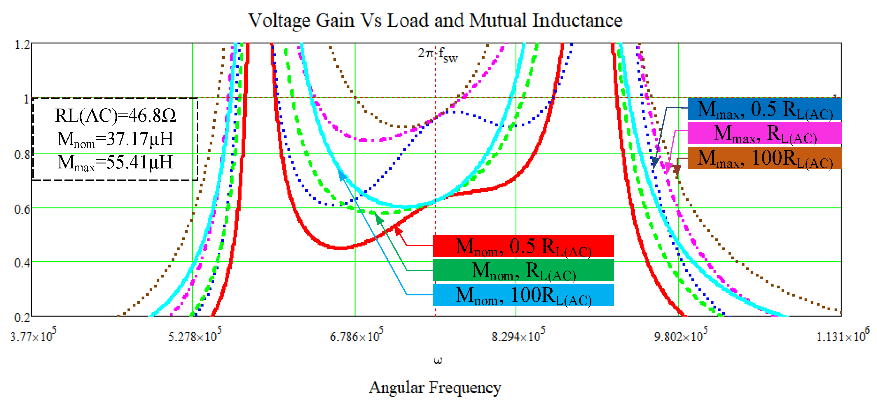
The voltage gain characteristic of the LCC-S WPT is very important to understand how the circuit works and how to control the system. The fundamental resonant angular frequency is selected to be ωo. The input impedance of DWPT, Zin, is expressed in (14) and the output to input voltage gain can be derived result in (15). The plots of the gain curve for various loads and mutual inductances in Figure 4 is based on the Table 1 parameters. These parameters can be selected freely depends on the desired design. However, in this paper, the selected parameters are same as the used parameters for hardware implementation. Figure 4 provides the information that the voltage gain of the DWPT system varies with the operation frequency, load, and mutual inductance. In terms of the load variation, this WPT has an independent load voltage gain at the designed frequency for a same mutual inductance. However, the variation of mutual inductance is proportional to the variation of voltage gain. Based on the presented curves, we can also see that the independent load frequency does not change with a different mutual coupling. This characteristic could be used to predict the output voltage if the system works at a fixed frequency. These curves contain information about the capacitive and inductive region which is useful to determine the Zero Voltage Switching (ZVS) and Zero Current Switching (ZCS) region. The ZVS transition frequency range is in the negative slope frequency range and ZCS transition frequency is in the range of positive slope frequency. However, the operation with switching frequency far from the independent load frequency could result in a lower efficiency due to the higher circulating current of the compensation loop.
3. Coils and Compensation Design
3.1. Coils Design
Many parameters, such as inductance, capacitance, resistance, and coupling coefficient, should be considered in designing the coils for WPT [21]. For DWPT, the receiver side in every designed position of the receiver should have optimum transferred power. The power transferred to the receiver is related to the mutual inductance between the transmitter and receiver sides which is affected by the self-inductance and coupling coefficient of the coils. Equation (2) shows that mutual inductance can be increased either by increasing the self-inductance of the coils or increasing the coupling coefficient of the coils. The Coupling coefficient can be increased by optimizing shape/dimension of the coil, increasing size, and utilizing a magnetic material to guide the magnetic field. In [22], the author stated that the solenoid coil with H-shaped magnetic exhibits a superior misalignment performance compared to the circular coil. However, it results in a larger and heavier coil. For a logistic robot, the air gap and coil size requirement are smaller compared to the Electric Vehicles. Therefore, a smaller size coil should be enough for this application. A coil that is not perfectly rectangular and not perfectly circular named as semi-rectangular coil shape as shown in Figure 5 was selected in this research because it is simple, low cost, and lightweight. The inner area of the coil must be left empty to avoid the eddy current effect due to the magnetic field path. Ferrite bars were used to guide the magnetic field. The best practice of the magnetic bar placement is to follow the coil area. However, in this experiment, due to the hardware and tools limitation, some part of the coil area is not covered by the ferrite bar. The resistance of the coils must be considered in the design to minimize the contribution of losses (PLp) due to the DC resistance of the coil (RLp) as expressed in (16). This resistance is related to the material, length and diameter of the wire used to build the coils. Increasing the self-inductance does not always result in the better efficiency because it could increase the DC resistance of the coil. The coils basically carry the high-frequency AC current, therefore, the skin effect is also considered and the Litz wire is used to solve this issue. In this study, the transmitter consists of three identical semi-rectangular coils and a single coil in the receiver. The important values that we have to obtain are the minimum (kmin) and maximum (kmax) coupling coefficients to define the nominal coupling coefficient (knom) as expressed in (17). The minimum and maximum coupling coefficients are measured when the receiver coil is in the middle of two transmitter coils and at the center point of a transmitter coil respectively. The parameters in Table 2 are based on the 6 cm distance between transmitter and receiver which is a reasonable distance for logistic robot application.
3.2. Compensation Circuit Design
The compensation components of the LCC-S should be carefully designed to ensure the optimum performance of the WPT system. The design steps are presented as follows:
Determine the specification of the system
This includes rating power (Po), Input and output voltage, and switching frequency (fsw). In selecting the switching frequency, a designer should aware of the requirement of the industry. In case of logistic robot, a standardized frequency operation has not existed yet. Therefore, converter size, power density, efficiency and cost are the main factors that need to be considered. Once the parameters have been determined, the output current can be determined by and secondary current calculated by .
Determine the coil parameters and receiver resonant capacitor
The values of the receiver parameters and the resonant capacitor can be determined by using the selected frequency, and a pickup value of either the resonant capacitor or the receiver self-inductance. Use (18) to calculate required Css or Ls.
Calculate the parallel resonant capacitor of transmitter side
The value of the optimum current of transmitter coil (Ipop) should be determined firstly by (19) and use the obtained value to calculate the Cpp value. It should be noted, this process might need to do the iterative calculation to have a suitable capacitor value that available in the market.
Determine the series resonant capacitor and resonant inductor of the transmitter side
The operation frequency and determined transmitter coil inductance can be inserted into (21) to determine the series resonant capacitance (Cps). The determined value of both Cps, and Lpr, must satisfy . Table 3 shows the compensator that has been used in this study.
4. Simulation and Experimental Verifications
Simulation and hardware implementation are discussed in this section. It includes the testing procedure at the various loads and coupling coefficients due to the misalignment of the coils.
4.1. Simulation
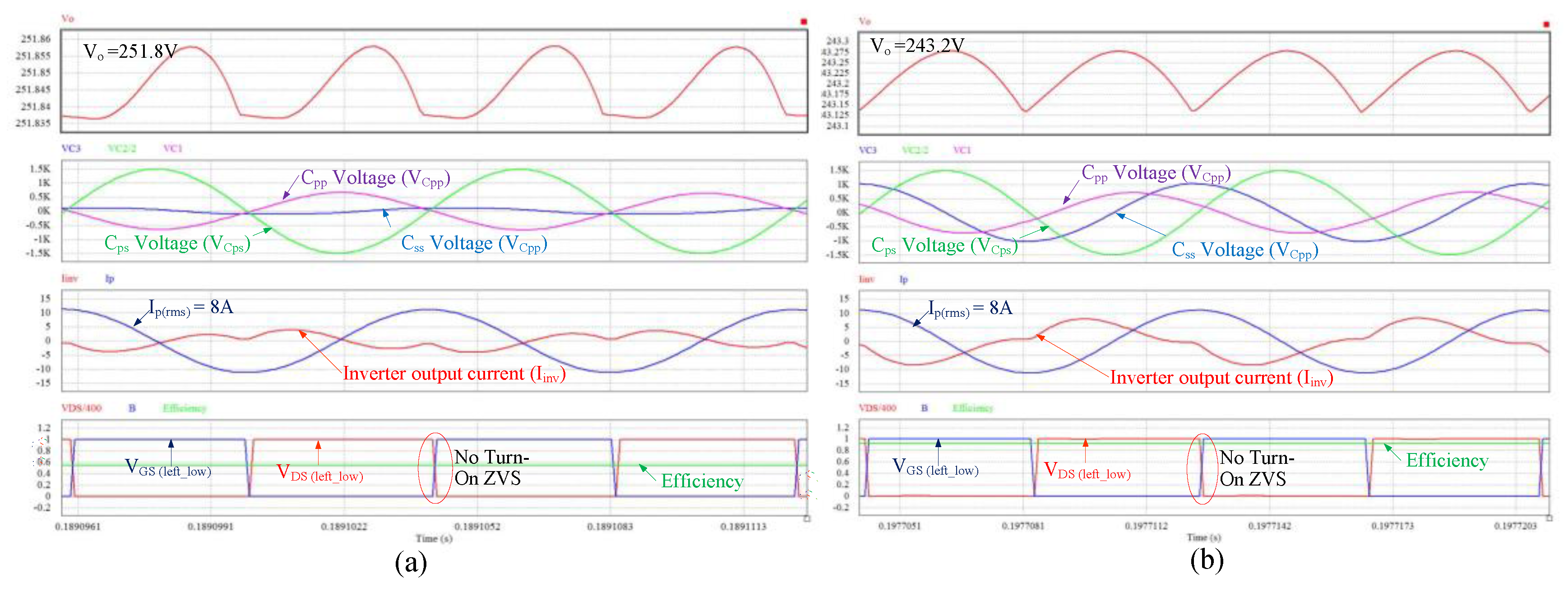
PSIM software has been used to simulate and evaluate the performance of the DWPT. The simulation included the parasitic components of the MOSFET and compensation ESR and has been conducted for a fixed frequency, various loads, and various mutual inductance conditions. Parameters in Table 1 and Table 2 were used for this simulation. The purpose is to verify the system before the real hardware is implemented. Figure 6 presents some key-waveforms of the simulation that include the output voltage, primary series capacitor voltage stress, transmitter current and efficiency of the selected case. The summary of the simulation result is also presented in Table 4. The result shows that the transmitter current is constant that results in a constant voltage stress of the primary series capacitor (Cps). The output voltage variation for the same coupling coefficient (k) occurs because of the voltage drop due to the presence of parasitic resistance.
4.2. Hardware Implementation
An inverter and a rectifier have been built and tested to verify the performance of the proposed DWPT. The input rating is set as 400 V, and the output power at the fully aligned condition is set to 1.5 kW. The MOSFET and diode used in this study are FCH072N60F and C3D10060, respectively. The voltage rating of the compensation capacitor should be carefully selected. For the LCC-S compensation type, the highest voltage stress occurs in the primary series resonant capacitor. The maximum voltage stress in the simulation is approximately 3 kV as shown in Table 4. For safety reasons, two film capacitors with 3 kV voltage rating are connected in series. The inductance value of the resonant inductance cannot be changed because the parallel resonant capacitor has been determined based on the desired transmitter current. However, a small inductance is preferred to avoid a large size of the compensation circuit. The value of this inductance can only be changed to vary the switching frequency range of the DWPT system. In this study, an inductor is constructed using the Litz wire and ETD 4949 core. The dynamic LCC-S WPT consisted of moveable and static parts to simulate the transmitter, which is static, and the receiver, which is moveable. We simulated the robot movement with only a moving receiver coil on a designed track. The experimental setup is shown in Figure 7.
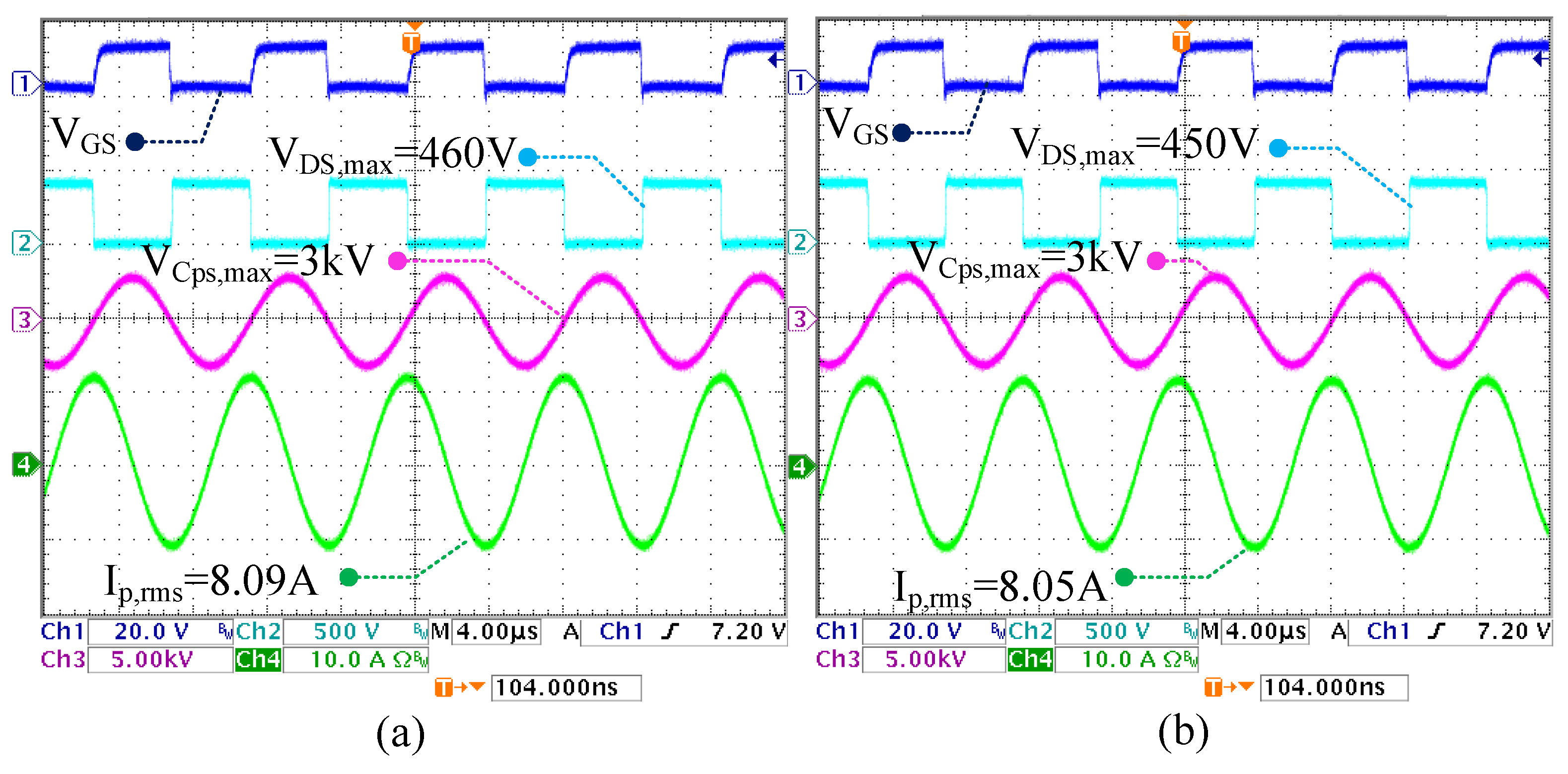
4.3. Performance at the Maximum Coupling Coefficient
The experiment has been conducted for various loads at a fixed frequency. In this condition, the receiver coil is fully aligned with one of the transmitter coils. The key waveforms are shown in Figure 8. From the waveforms, we can see that the coil current is constant for 100 W to 1.5 kW output power. In terms of efficiency, the system achieved the maximum efficiency of 91.02% at 1.5 kW rated power.
4.4. Dynamic Performance
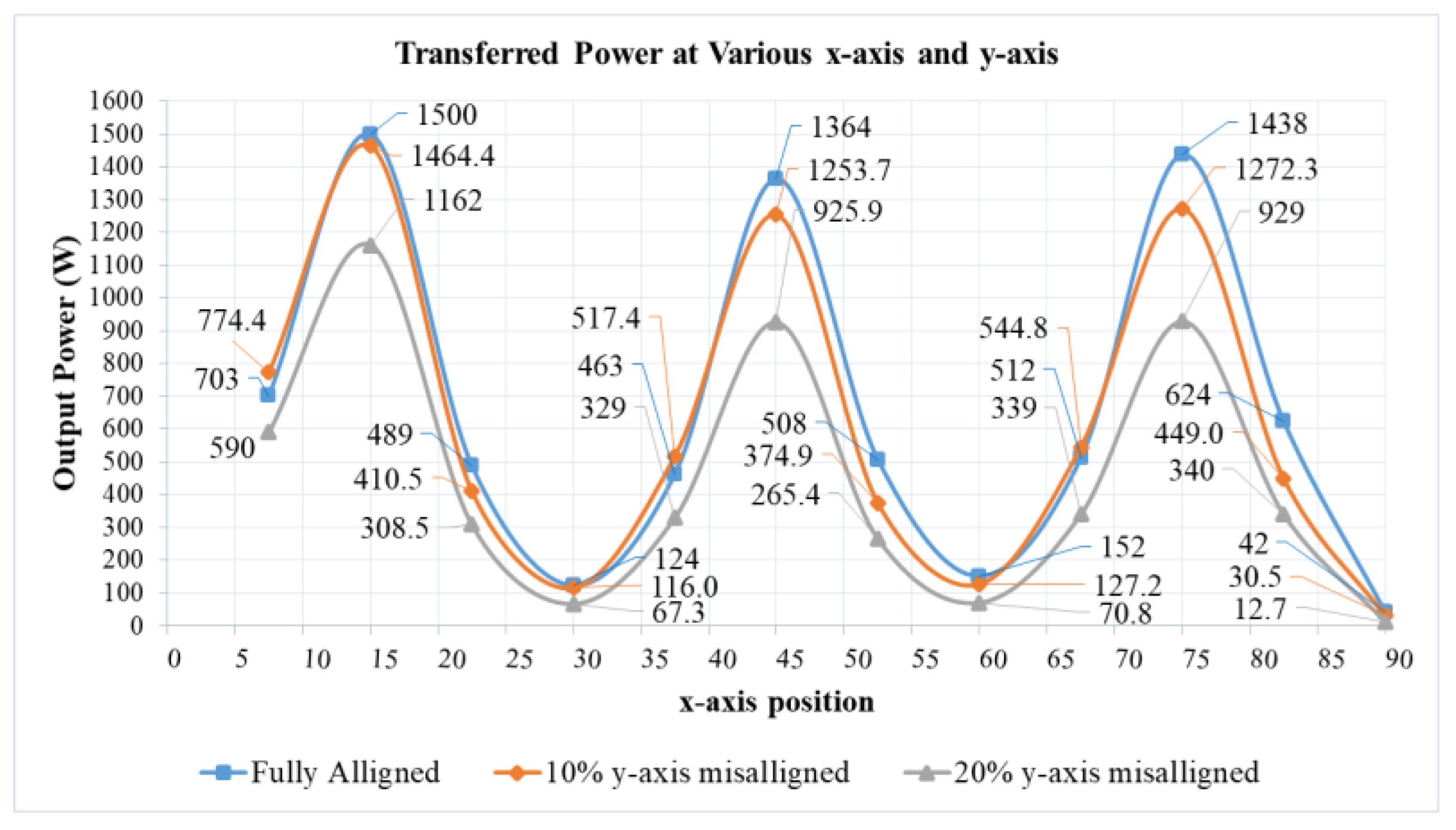
In this test, the receiver side moves along the rail that referred the x-axis with 0.7 cm/s velocity. This movement creates the variation of mutual inductance and coupling coefficient. The testing has been done with a constant resistance load with three y-axis (vertical) misalignment conditions. Originally, the receiver coil has no vertical misalignment with the transmitter coil (fully aligned).
Then, the receiver is misaligned 10% and 20% to to the y-axis. The measurement of the output power and efficiency are presented in Figure 9 and Figure 10 respectively. The transferred power varies depending on the position of the receiver coil. There are three peaks of the power and the efficiency curve that occur exactly at the x-axis center of the transmitter coil. Maximum power is obtained at x = 15 cm with an efficiency of 91.02%. The averaged efficiency over the x-axis at full-aligned, 10% misaligned, and 20% misaligned are 74.51%, 72.33%, and 65.53% respectively. The power and efficiency at x = 45 cm, which is exactly in the middle of the three transmitter coils, has less transferred power than that at x = 15 cm or x = 75 cm. The reason for this issue is because of the magnetic flux interaction of the middle coil with the other two coils (left and right). The direction of the current is reversed to each other in the neighborhood coils that cancel out the magnetic flux. The average output power variation at the fully aligned position to 10% and 20% y-axis misaligned is 7.31% and 24.6% respectively, while the average efficiency variation of the correspondent position is 0.7% and 3.4%.
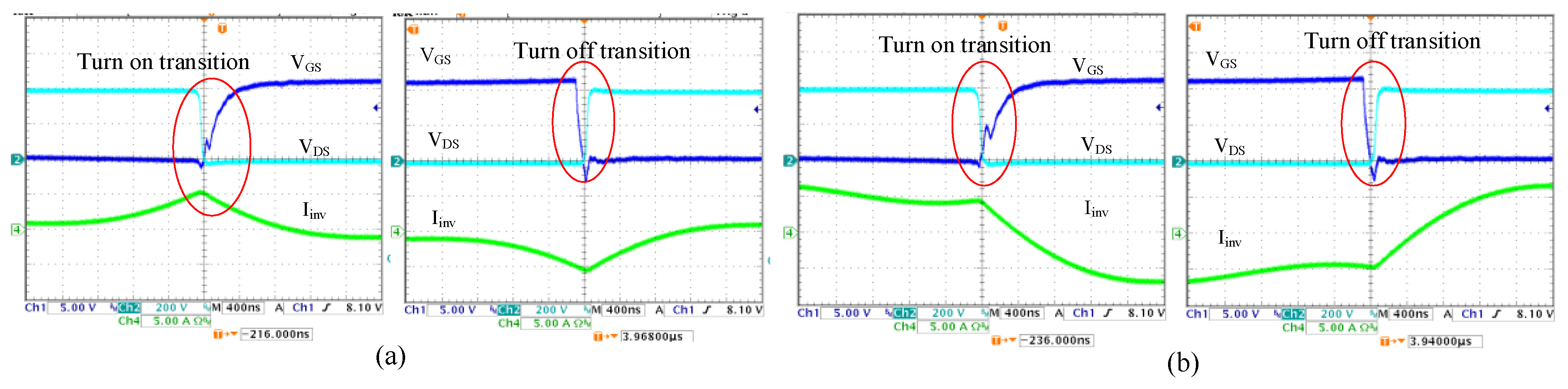
4.5. Zero-Voltage Switching Transition
Zero-voltage switching transition is essential to increase the efficiency and to minimize the electromagnetic interference. Figure 11 shows the switching transition condition at 150 W and 1.5 kW output power. Both waveforms show that the boundary ZVS condition is achieved. This finding is related to the gain curve illustrated in Figure 4, which shows that the switching frequency at 120 kHz does not result the boundary ZVS condition. By contrast, reducing the switching frequency could reach the boundary ZVS condition, which was achieved in this experiment. The selection of the component and switching frequency has an important role in achieving soft switching.
5. Conclusions
This paper has presented the theoretical analysis, simulation, and hardware design considerations of the dynamic LCC-S DWPT. The system has been successfully implemented with small coils and tested with various variables at a fixed frequency. Generally, the results are consistent with the theoretical and simulation results that show that the proposed topology can be used for DWPT system, particularly for the logistic robot charging system. The maximum efficiency achieved 91.02% at 1.5 kW fully aligned position. The proposed topology also has a robust output voltage response to the load variations, even with coupling coefficient variation. Closed loop control and post regulator stage can be added to regulate the output voltage. The results also showed that the transmitter current could be maintained constant if the input voltage and frequency were maintained. As for switching transition, the boundary ZVS condition could be achieved by slightly decreasing the switching frequency.
Acknowledgments
The authors would like to acknowledge the financial support of the Ministry of Science and Technology of Taiwan through grant number NSC 103-2221-E-011-064-MY3.
Author Contributions
Marojahan Tampubolon designed, debugged the system, and wrote the paper; Laskar Pamungkas built some part of hardware and performed the experiment. Huang-Jen Chiu, Yu-Chen Liu, and Yao-Ching Hsieh provided all material for experiment, supervised the design, analysis, experiment, and editing the paper.
Conflicts of Interest
The authors declare no conflict of interest.
References
- Bonkenburg, T. Robotics in Logistics: A DPDHL Perspective on Implications and Use Cases for the Logistics Industry; DHL Customer Solutions & Innovation: Bonn, Germany, 2016; p. 4. [Google Scholar]
- Bhasin, K.; Clark, P. How Amazon Triggered a Robot Arms Race. Available online: http://fromm.usfca.edu/Spring2017Handouts/Levy%20Week%203.4.pdf (accessed on 27 July 2017).
- Robotics, L. Collaborative, Autonomous Robots That Just Work. Available online: http://www.locusrobotics.com/features/autonomous-robots/ (accessed on 25 July 2017).
- Boys, J.T.; Covic, G.A.; Green, A.W. Stability and control of inductively coupled power transfer systems. IEE Proc. Electr. Power Appl. 2000, 147, 37–43. [Google Scholar] [CrossRef]
- Covic, G.A.; Boys, J.T. Modern Trends in Inductive Power Transfer for Transportation Applications. IEEE J. Emerg. Sel. Top. Power Electr. 2013, 1, 28–41. [Google Scholar] [CrossRef]
- Li, T.; Wang, X.; Zheng, S.; Liu, C. An Efficient Topology for Wireless Power Transfer over a Wide Range of Loading Conditions. Energies 2018, 11, 141. [Google Scholar] [CrossRef]
- Obayashi, S.; Tsukahara, H. EMC Issues on Wireless Power Transfer. In Proceedings of the 2014 International Symposium on Electromagnetic Compatibility, Tokyo, Japan, 12–16 May 2014; IEICE: Tokyo, Japan, 2014; pp. 601–604. [Google Scholar]
- Wen, F.; Huang, X. Optimal Magnetic Field Shielding Method by Metallic Sheets in Wireless Power Transfer System. Energies 2016, 9, 733. [Google Scholar] [CrossRef]
- Suzuki, S.-N.; Ishihara, M.; Kobayashi, Y. The Improvement of the Noninvasive Power-Supply System Using Magnetic Coupling for Medical Implants. IEEE Trans. Magn. 2011, 47, 2811–2814. [Google Scholar] [CrossRef]
- Lu, Y.; Ma, D. Wireless Power Transfer System Architectures for Portable or Implantable Applications. Energies 2016, 9, 1087. [Google Scholar] [CrossRef]
- Junaid, A.; Konoiko, A.; Zweiri, Y.; Sahinkaya, M.; Seneviratne, L. Autonomous Wireless Self-Charging for Multi-Rotor Unmanned Aerial Vehicles. Energies 2017, 10, 803. [Google Scholar] [CrossRef]
- Campi, T.; Cruciani, S.; Feliziani, M. Wireless Power Transfer Technology Applied to an Autonomous Electric UAV with a Small Secondary Coil. Energies 2018, 11, 352. [Google Scholar] [CrossRef]
- Lee, S.-H.; Kim, J.-H.; Lee, J.-H. Development of a 60 kHz, 180 kW, Over 85% Efficiency Inductive Power Transfer System for a Tram. Energies 2016, 9, 1075. [Google Scholar] [CrossRef]
- Kobayashi, D.; Imura, T.; Hori, Y. Real-time coupling coefficient estimation and maximum efficiency control on dynamic wireless power transfer using secondary DC-DC converter. In Proceedings of the IECON 2015—41st Annual Conference of the IEEE Industrial Electronics Society, Yokohama, Japan, 9–12 November 2015; pp. 004650–004655. [Google Scholar]
- Lovison, G.; Imura, T.; Hori, Y. Secondary-side-only simultaneous power and efficiency control by online mutual inductance estimation for dynamic wireless power transfer. In Proceedings of the IECON 2016—42nd Annual Conference of the IEEE Industrial Electronics Society, Florence, Italy, 23–26 October 2016; pp. 4553–4558. [Google Scholar]
- Angelis, A.D.; Dionigi, M.; Wang, Q.; Che, W.; Mastri, F.; Monti, G. Resonant inductive wireless power transfer links operating in a coupling-independent regime: Theory and experiments. In Proceedings of the 2017 IEEE International Instrumentation and Measurement Technology Conference (I2MTC), Torino, Italy, 22–25 May 2017; pp. 1–6. [Google Scholar]
- Feng, H.; Cai, T.; Duan, S.; Zhao, J.; Zhang, X.; Chen, C. An LCC-Compensated Resonant Converter Optimized for Robust Reaction to Large Coupling Variation in Dynamic Wireless Power Transfer. IEEE Trans. Ind. Electr. 2016, 63, 6591–6601. [Google Scholar] [CrossRef]
- Systems Control Technology, Inc. Roadway Powered Electric Vehicle Project Track Construction And Testing Program Phase 3D; Systems Control Technology, Inc.: Palo Alto, CA, USA, 1994. [Google Scholar]
- Chou, C.-Y.; Tampubolon, M.; Lin, J.-Y.; Hsieh, Y.-C.; Chiu, H.-J. Study on LCC-C Wireless Power Transfer. In Proceedings of the 2017 IEEE Wireless Power Transfer Conference (WPTC), Taipei, Taiwan, 10–12 May 2017; pp. 1–4. [Google Scholar]
- Pantic, Z.; Bai, S.; Lukic, S.M. ZCS LCC Compensated Resonant Inverter for Inductive-Power-Transfer Application. IEEE Trans. Ind. Electr. 2011, 58, 3500–3510. [Google Scholar] [CrossRef]
- Waters, B.H.; Mahoney, B.J.; Lee, G.; Smith, J.R. Optimal coil size ratios for wireless power transfer applications. In Proceedings of the 2014 IEEE International Symposium on Circuits and Systems (ISCAS), Melbourne, Australia, 1–5 June 2014; pp. 2045–2048. [Google Scholar]
- Fujita, T.; Yasuda, T.; Akagi, H. A Dynamic Wireless Power Transfer System Applicable to a Stationary System. IEEE Trans. Ind. Appl. 2017, 53, 3748–3757. [Google Scholar] [CrossRef]
Figure 1.
The system architecture of the Dynamic Wireless Power Transfer (DWPT) (a) with a single track; (b) with segmented lumped coils.
Figure 1.
The system architecture of the Dynamic Wireless Power Transfer (DWPT) (a) with a single track; (b) with segmented lumped coils.

Figure 2.
Schematic of WPT with LCC-S Compensation.
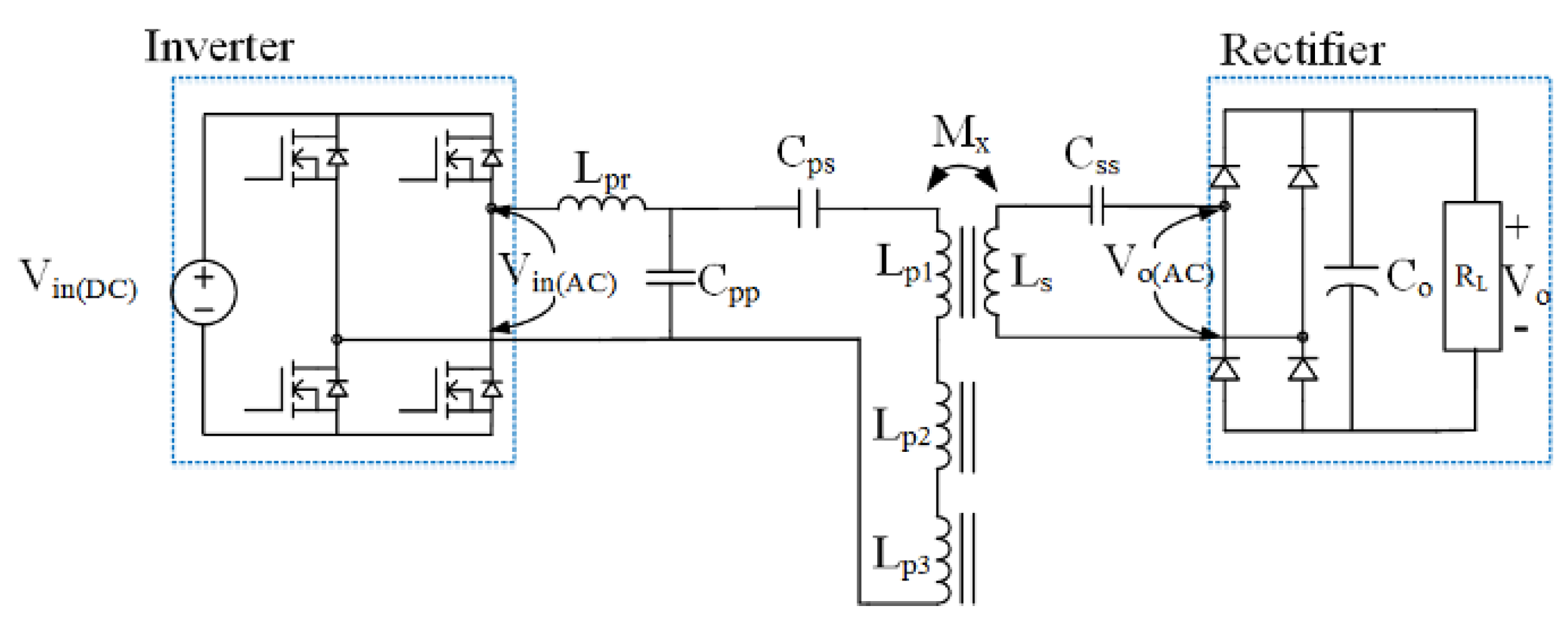
Figure 3.
AC Modeling of LCC-S WPT (a) with the induced voltage and (b) with the reflected impedance.
Figure 3.
AC Modeling of LCC-S WPT (a) with the induced voltage and (b) with the reflected impedance.

Figure 4.
Gain curve characteristic of LCC-S compensated DWPT for various load and mutual inductance conditions.
Figure 4.
Gain curve characteristic of LCC-S compensated DWPT for various load and mutual inductance conditions.

Figure 5.
Semi-rectangular coil of the DWPT.
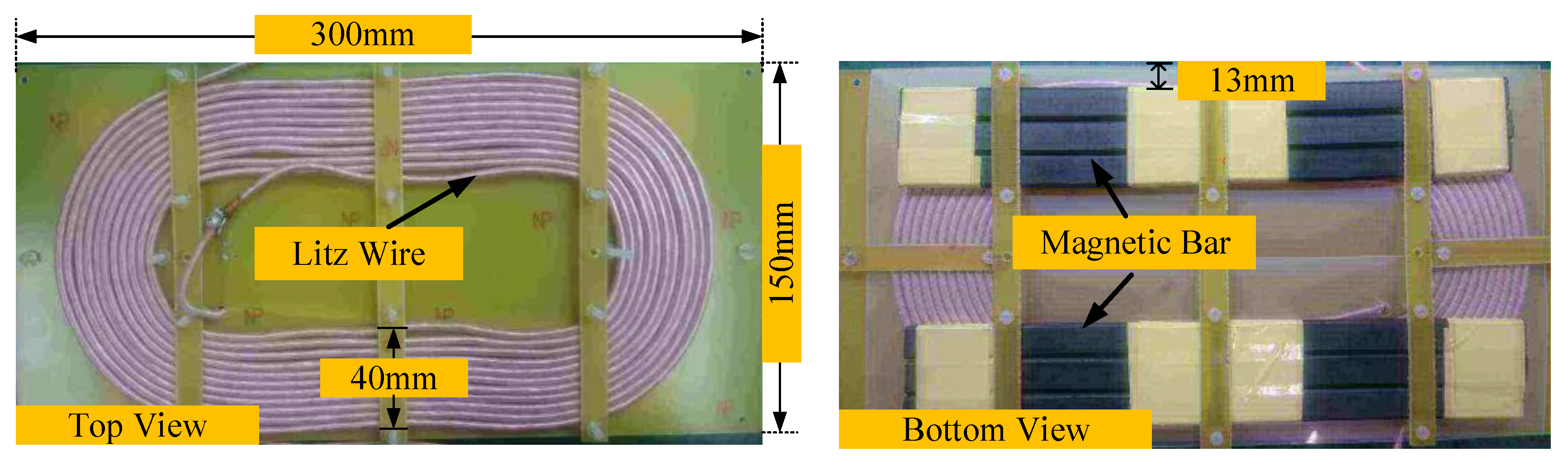
Figure 6.
Simulation of dynamic WPT at nominal coupling coefficient at (a) 150 W (b) 1.5 kW.

Figure 7.
Experimental setup of DWPT with LCC-S compensation.
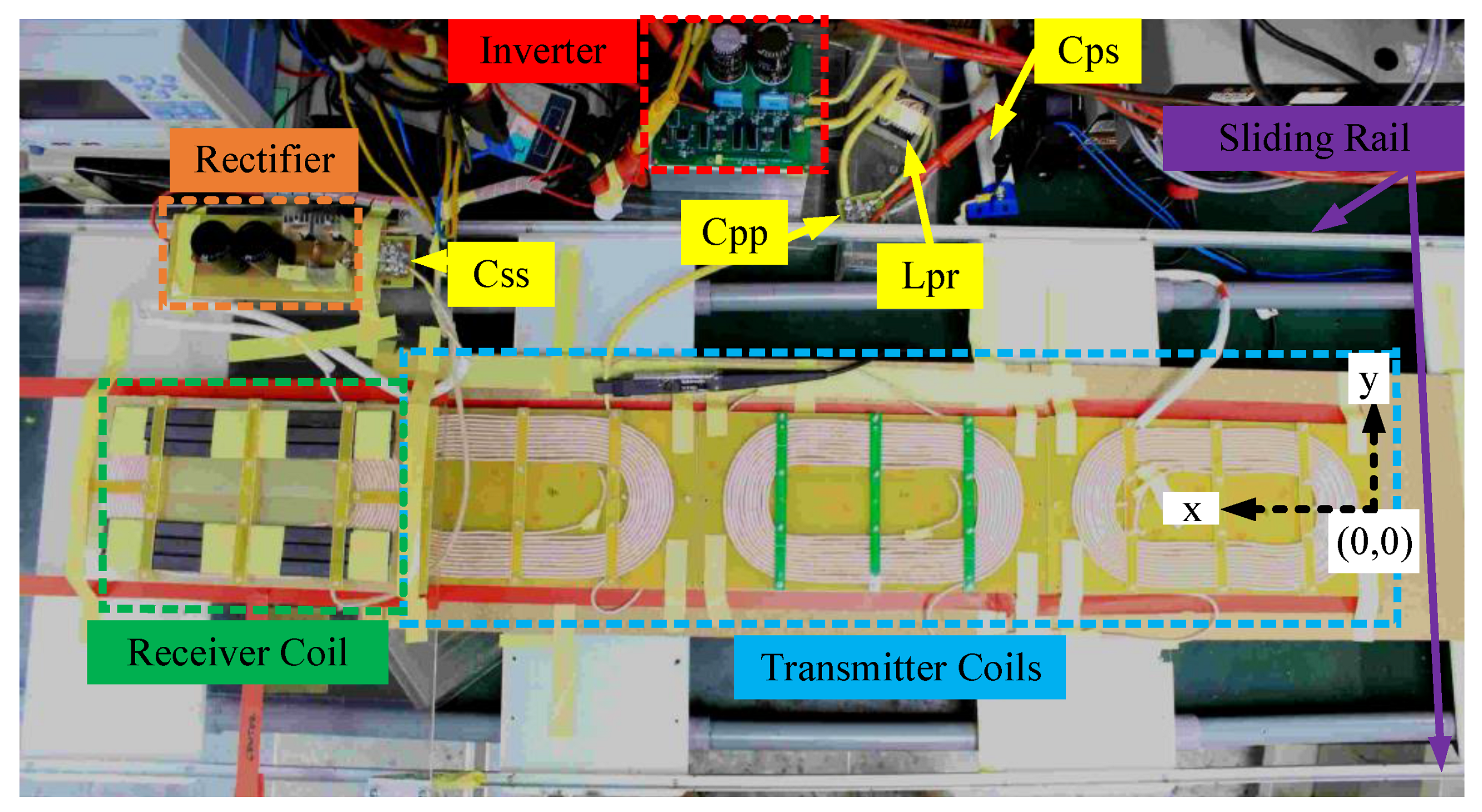
Figure 8.
Key-waveforms of LCC-S compensation dynamic WPT at maximum coupling coefficient with various loads. (a) Po = 150 W (b) Po = 1.5 kW.
Figure 8.
Key-waveforms of LCC-S compensation dynamic WPT at maximum coupling coefficient with various loads. (a) Po = 150 W (b) Po = 1.5 kW.

Figure 9.
The measurement of transferred power of LCC-S DWPT under the various x-axis position and y-axis misalignment.
Figure 9.
The measurement of transferred power of LCC-S DWPT under the various x-axis position and y-axis misalignment.

Figure 10.
The measurement of efficiency of LCC-S DWPT under the various x-axis position and y-axis misalignment.
Figure 10.
The measurement of efficiency of LCC-S DWPT under the various x-axis position and y-axis misalignment.
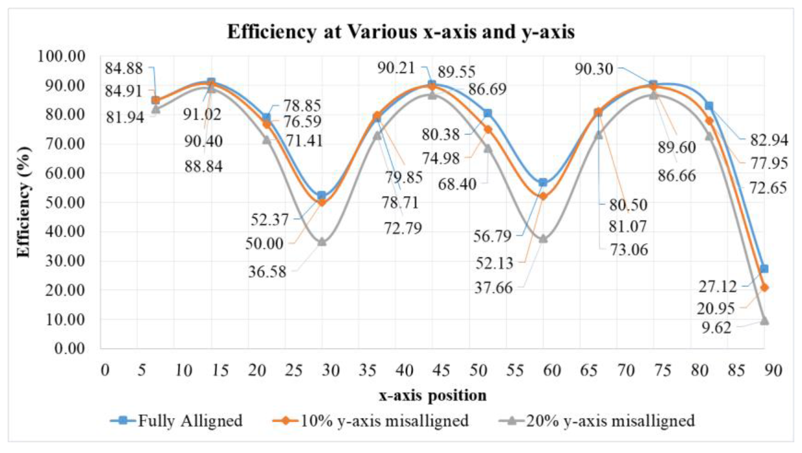
Figure 11.
Zero switching transition at (a) 150 W (b) 1.5 kW.

Table 1.
Parameters of the LCC-S WPT.
| Components | Units | Values |
|---|---|---|
| Transmitter inductance (Lp) | µH | 410.4 |
| Receiver inductance (Ls) | µH | 143.9 |
| Mutual inductance (M) | µH | 24.93 |
| Series resonant inductor (Lpr) | µH | 60 |
| Parallel primary resonant capacitor (Cpp) | nF | 29.4 |
| Series primary resonant capacitor (Cps) | nF | 5 |
| Series primary resonant capacitor (Css) | nF | 12.2 |
| AC equivalent output resistance (RL(AC)) | Ω | 48.634 |
Table 2.
Parameters of constructed coil.
| Parameters | Units | Values |
|---|---|---|
| Self-inductance of transmitter coil 1 Lp1 | µH | 137.3 |
| Self-inductance of transmitter coil 2 Lp2 | µH | 143.3 |
| Self-inductance of transmitter coil 3 Lp3 | µH | 141.4 |
| Self-inductance of receiver coil 4 Ls | µH | 143.9 |
| Total transmitter inductance Lp | µH | 410.4 |
| Minimum coupling coefficient (kmin) | - | 0.102 |
| Maximum coupling coefficient (kmax) | - | 0.228 |
| Nominal coupling coefficient (knom) | - | 0.153 |
| DC resistance/coil | mΩ | 50 |
| Number of turn/coil | - | 22 |
| Ferrite bar size | mm | 14 × 5 × 120 |
Table 3.
Compensator components parameters.
| Component | Unit | Value | ESR |
|---|---|---|---|
| Primary Series Resonant Inductor (Lp) | µH | 60 | 6 mΩ |
| Primary Series Resonant Capacitor (Cps) | nF | 5 | 15 mΩ |
| Primary Parallel Resonant Capacitor (Cpp) | nF | 29.4 | 19 mΩ |
| Secondary Series Resonant Capacitor (Css) | nF | 12.2 | 9.7 mΩ |
| Designed Switching Frequency (fsw) | kHz | 120 | |
Table 4.
Simulation result at various coupling coefficient condition.
| k | Power (W) | Vo (V) | VC2,max (kV) | Ip,rms (A) | η (%) |
|---|---|---|---|---|---|
| 0.1026 | 150 | 165.5 | 2.99 | 8.08 | 59.7 |
| 1500 | 151.15 | 2.98 | 8.1 | 87.29 | |
| 0.153 | 150 | 251.8 | 2.99 | 8.1 | 56.4 |
| 1500 | 243.2 | 2.98 | 8 | 92.2 | |
| 0.228 | 150 | 393 | 2.99 | 8.05 | 48.1 |
| 1500 | 367.2 | 2.99 | 8.06 | 92.6 |
© 2018 by the authors. Licensee MDPI, Basel, Switzerland. This article is an open access article distributed under the terms and conditions of the Creative Commons Attribution (CC BY) license (http://creativecommons.org/licenses/by/4.0/).
Share and Cite
MDPI and ACS Style
Tampubolon, M.; Pamungkas, L.; Chiu, H.-J.; Liu, Y.-C.; Hsieh, Y.-C. Dynamic Wireless Power Transfer for Logistic Robots. Energies 2018, 11, 527. https://doi.org/10.3390/en11030527
AMA Style
Tampubolon M, Pamungkas L, Chiu H-J, Liu Y-C, Hsieh Y-C. Dynamic Wireless Power Transfer for Logistic Robots. Energies. 2018; 11(3):527. https://doi.org/10.3390/en11030527
Chicago/Turabian StyleTampubolon, Marojahan, Laskar Pamungkas, Huang-Jen Chiu, Yu-Chen Liu, and Yao-Ching Hsieh. 2018. "Dynamic Wireless Power Transfer for Logistic Robots" Energies 11, no. 3: 527. https://doi.org/10.3390/en11030527
Note that from the first issue of 2016, this journal uses article numbers instead of page numbers. See further details here.