Impact of Coil Misalignment in Data Transmission over the Inductive Link of an EV Wireless Charger


1
Department of Electrical Engineering, University of Málaga, 29016 Málaga, Spain
2
Power Electronics, Machines and Power System, Aston University, Birmingham B4 7ET, UK
*
Author to whom correspondence should be addressed.
Energies 2018, 11(3), 538; https://doi.org/10.3390/en11030538
Submission received: 18 January 2018
/
Revised: 23 February 2018
/
Accepted: 26 February 2018
/
Published: 2 March 2018
(This article belongs to the Section I: Energy Fundamentals and Conversion)
Abstract
:The penetration rate of electric vehicles (EVs) will experience a relative increment in the future, so easy to use ways to recharge will be demanded. In this sense, wireless charging represents a safe charging method that minimises user intervention. In a similar way to conductive charge, wireless charging requires some information exchange between the charger primary side and secondary side (battery) for safety and operational reasons. Thus, wireless chargers depend on a communication system for their controlled and correct operation. This paper analysed the communication performance of a wireless EV charger in which the communiction device is part of the wireless power transfer system. Particularly, this work studies how the communication system reacts to power coil displacements, which commonly occur in their conventional performance. The results show that the compensation topology selected to ensure the resonant operation clearly impacts on the communication performance. In particular, the theoretical model and the simulation results demonstrate that the asymmetrical compensation topologies are more stable in terms of the wireless communication channel capacity.
1. Introduction
Wireless charging is now a reality and a wide range of commercial low-power products are equipped with this technology [1]. In addition to common mobile phone devices and some biomedical electronics, the commodity of use associated with wireless power transfer also makes it attractive for medium power devices (kW level). In this range, electric vehicles (EVs) are clear candidates that could benefit from the wireless power transfer, to charge their batteries in a safer and easier way. Inductively Coupled Power Transfer (ICPT) technology is the most mature mechanism applied to the wireless charge of EVs [2]. It basically consists of a pair of loosely coupled coils. The one in the pavement (referred as the primary side) is excited with a time-varying current, which induces a voltage in the secondary coil, that is, the coil placed in the EV chassis. This voltage is employed to charge the battery that is connected to the secondary coil [3]. To enhance the power transfer, reactive components (typically named compensation networks) are added to both coils. Power converters are also inserted in the chargers to ensure a high-frequency magnetic field [4].
The adequate operation of the EV wireless chargers requires some mechanisms that control the correct current and/or voltage, which are provided to the battery once permitted. Thus, the primary and the secondary side need some information exchange [5] (e.g., some billing information or some electrical status about the battery). This information does not only occur during the charge, but it can also occur with no charge. For instance, in a V2G (Vehicle-to-Grid) scenario, the vehicle and the grid need to exchange some data about prices or the battery State-Of-Charge (SOC) to decide whether it is convenient or not to perform a charge or a discharge [6].
For this information exchange, wired communication is advised against, as it will eliminate the main benefits reported by the wireless chargers. Several wireless-based communication techniques have been proposed as alternatives. The more straightforward strategy consists of opting for some commercial wireless modules, which could be inserted in the primary and secondary sides. Coordination between the modules and some security drawbacks are the main concerns which could make this solution inoperative [7]. To obtain more reliable communication, these solutions can be complemented, or even avoided, by using the same wireless link that is involved with the wireless charger.
Several papers have been published regarding the use of the coils for the simultaneous transmission of data and power in EV wireless chargers. In [8], the authors designed a scheme where both data and power are transmitted at the same time. Specifically, data and power are generated at different frequencies (1.6 MHz and 22.4 kHz, respectively). A similar scheme was published in [9]. Both schemes are complex to implement, as they have to add high-frequency data communication modules, extra coils and filters to separate the power and data processing accordingly. As demonstrated in [10,11], additional costs can be avoided if the power converters employed to create the high-frequency signal generate the data signal too. According to this strategy, data and power are transmitted at the same frequency. The work in [10] included experimental results which show how this kind of combination is feasible for a 700-W wireless charger operating at 22 kHz. In fact, the spectrum of the data signal is centered at the frequency in which the wireless charger resonates. On the other hand, the data protocol is based on the BFSK (Binary Frequency Shift Keying).
As demonstrated in [10], when the data and the power are transmitted at the same frequency, a data protocol needs to then be designed. To do so, some features of the wireless link over the inductive channel need to be characterised. Among these characteristics, it is necessary to know the communication capacity of the link, which limits the bit rate that the wireless channel can support. In contrast to other wireless communication schemes, the inductive link involved in ICPT technology is based on near-field transmissions. Moreover, it is specially designed to maximise the efficiency of power transfer on specific conditions, such as the coil positions and their relative distances [12]. This design goal differs from the one employed in traditional wireless communication systems, which aim to maximise the power transfer with an efficiency equal to 50%.
The conditions assumed in the design process do not always hold during the operation of the wireless chargers. In fact, it is expected that there will be an increased number of scenarios where coil misalignments will be present. This is due to the promotion of the use of wireless charge while the vehicle is moving (dynamic charge) or temporally stopped due to traffic signals (stationary charge) [13]. The effect of coil misalignment has already been studied in regard to power transfer, but the analysis regarding its impact on the communication channel is still missing [14].
This paper analyses the capacity of the wireless channel created between the two power coils. In particular, it is based on the scheme proposed in [10] where both data and power signals are transmitted at the same frequency in order to avoid filters, high-frequency communication modules and extra coils to couple the data to the power circuits. Specifically, it studies how this parameter, which represents an upper bond for the data bit rate, is affected by usual coil misalignments (vertical and/or horizontal). The study is carried out for different compensation topologies in order to derive conclusions about the impact of the compensation networks’ selections for wireless data transfer. Some previous works have addressed the capacity of an inductive link [15,16]. However, in these works the coils were intended for low power applications, so the systems have characteristics that cannot be applied to EV wireless chargers. Firstly, they assume that both coils share the same topology (number of turns and dimensions). In an EV, the coil in the pavement is usually bigger than the one in the car in order to improve the coil misalignment behavior [2]. In addition, they work under the assumption that the coupling between the coils is so weak that the primary current is not affected by the impedance reflected from the secondary side. As shown in [17], this assumption is not valid for EV wireless chargers. Moreover, low power applications relay on a Series–Series compensation network, but other matching topologies can be found in EV wireless chargers [18,19]. Thus, in contrast to [15,16] this paper extends the study of the capacity offered by an inductive link with the following main contributions:
- (1).
- The coils are realistic for EV applications in terms of their dimensions and size.
- (2).
- Four types of compensation networks are considered, as Series–Series is not the only option considered in EV wireless chargers.
- (3).
- The reflected impedance is not neglected when deriving the electrical magnitudes affecting the computation of the channel capacity.
- (4).
- The vertical, horizontal and joint vertical and horizontal types of misalignments are analysed.
This study is based on a theoretical approach for each of the four single-resonant compensation networks. The theoretical models have been compared with simulation results, which show good agreement. For all the types of tested misalignments, the Series–Series compensation network was revealed to be the topology with the lowest stability in terms of variations of its channel capacity. In contrast, the asymmetrical topologies (series-parallel and parallel-series) were the compensation networks demonstrating better tolerance to coil misalignment from the communication point of view.
The rest of the paper is organised as follows: Section 2 overviews the structure of wireless chargers for electric vehicles. Section 3 presents the theoretical model used to compute the capacity of the wireless channel offered by the inductive link when considering misalignments and different compensation topologies. Section 4 presents and studies the results obtained by the developed model for a typically-designed EV wireless charger. The model is contrasted with some simulation results, showing a good agreement. Finally, Section 5 presents the main conclusions of our work.
2. Overview of a Wireless EV Charger
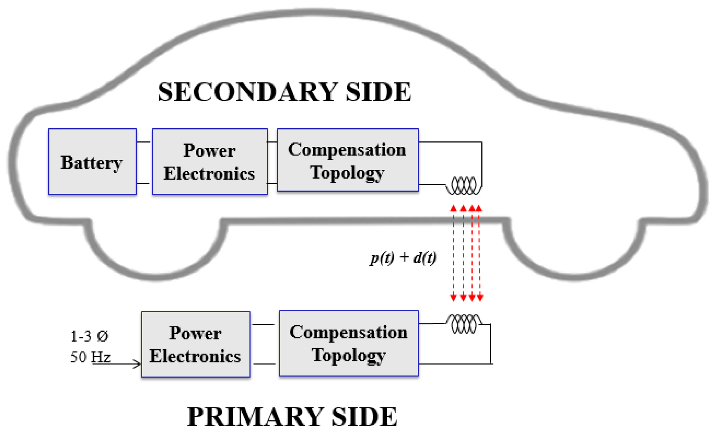
The structure of an ICPT wireless charger for an EV is illustrated in Figure 1.
In this scheme, the inductive link formed by the EV wireless charger is used to transfer the power () and the data (), as done in [8,9,10]. The core of the charger is the pair of coils. When a time-varying current traverses the primary coil, a magnetic field is then generated, according to Ampère’s law. On the other hand, when this magnetic field is present in the secondary coil, a voltage is induced in this element, as expressed by Faraday’s law. The induced voltage depends on the strength of the magnetic field and how much of the magnetic flux traverses the secondary coil. Thus, the relative distance between the coils as well as their misalignment have an impact on the induced voltage. In a lumped equivalent circuit, this phenomenon is modelled with the coupling factor () or the related mutual inductance (.
In order to have reasonably-sized coils, the magnetic field involved in this process is in the frequency range of 20–100 kHz [4]. This implies that the current injected to the primary coil must be in the aforementioned frequency range. The frequency conversion from the one provided by the grid (50–60 Hz) to the one required is performed by power converters, which are installed in the primary and the secondary sides. Therefore, the EV wireless charger depends on an inverter in the primary side and a rectifier in the secondary side. The topology of the inverter differs according to the power requirements [20].
The works in [10] and in [8] incorporated a data signal into the inductive link. In particular, the work in [10] incorporated one switch connected to the coil, to transmit the information. Both data and power signals were transmitted at the same frequency in order to avoid additional components, such as filters or extra coils. These elements are necessary to couple the data signal to the power one when both are generated at different frequencies.
Other components of the EV wireless chargers are the compensation networks. These are reactive elements that help to ensure resonant operation when a predetermined set of conditions holds (e.g., the relative position between the coils). Although more complex compensation topologies [19,21] exist, the single-resonant ones are the most common due to their simplicity. In these schemes, a primary capacitor () is installed on the primary side and a secondary capacitor () is also placed on the secondary side. The single-resonant compensation topologies are referred to as Series–Series (SS), Series–Parallel (SP), Parallel–Series (PS) and Parallel–Parallel (PP). The first term refers to the type of connection between the primary coil and the capacitor installed on this side. On the other hand, the second term in this nomenclature describes the connection between the secondary coil and the secondary capacitor.
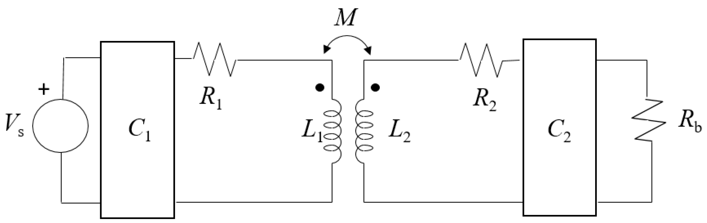
The values of the capacitors depend on the topology and the relative positions of the coils. In the design process, a certain distance between the coils is assumed so that a specific mutual inductance (Mi) is utilised during the computation of and . An equivalent circuit, as shown in Figure 2, can be used to determine the correct capacitors.
and represent the Equivalent Series Resistances (ESR) of the coils, whereas stands for the equivalent resistance of the battery. can be the data or the power signal. In our study, corresponds to the information source.
As previously stated, the goal of introducing the capacitors is to allow the system to operate under resonant conditions. When this condition holds, the input impedance seen by the source should have a null imaginary part. The works in [22,23] show how the values of the capacitors are computed in order to verify this condition under specific relative positions between the coils. Firstly, is computed to resonate with the secondary coil at the resonant operational frequency (). The value of does not depend on the compensation topology. Then, the impedance reflected from the secondary to the primary side is obtained. With the use of the reflected impedance, it is possible to derive the impedance seen by the source by analyzing a non-coupled circuit, which depends on the compensation topology. is designed so that the imaginary part of the impedance seen by the source is null. The equations in Table 1 show how the capacitors are computed for each single-resonant compensation topology.
It is important to note that the process for defining the values of the capacitors only focuses on obtaining an input impedance with a null reactance. Thus, it does not force impedance matching as conventional communication systems do, because communication systems and wireless power transfer chargers are designed based on two different goals. The goal of a wireless power transfer system is to perform transmission efficiently [24]. In contrast, the impedance matching strategy followed by communication systems derives the maximum power transmission but with an efficiency equal to 50%.
As can be observed, the appropriate values for the capacitor, , depend on the coils’ relative placements, which are modeled by . The charger is constructed by imposing design conditions, such as the distance between the coils. However, these conditions may not hold because of coil misalignments. The consequences of this effect are explained in the next section.
3. Theoretical Analysis of the Coil Misalignment Effects on the Wireless Channel Capacity
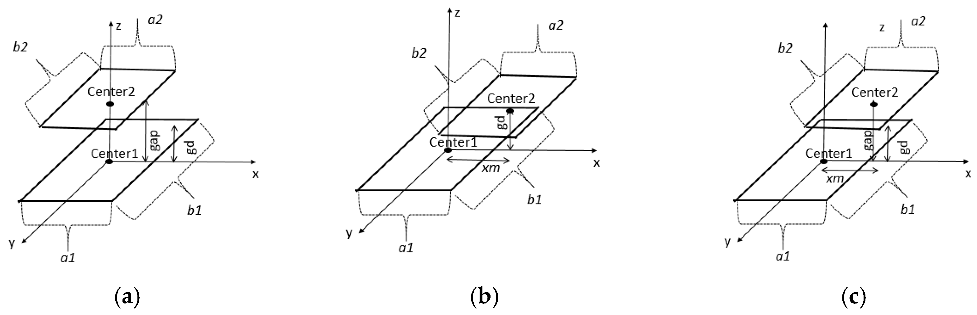
Coil misalignment refers to the condition in which the two elements do not keep a relative distance equal to the one considered in the design process for any part constituting them. There are three main types of misalignments: vertical, horizontal and joint vertical–horizontal. Figure 3 illustrates these misalignments for square coils, but it is also valid for other kind of coil. As in practical EV wireless charger implementations, the primary coil (with dimensions ) is bigger than the secondary coil, which has a size equal to .
In vertical misalignment, the centers of the two coils ( and ) are placed in a line perpendicular to the planes where the primary and the secondary coils are. In the design process of the coils to determine their features (numbers of turns, the dimensions, the cable section, etc.), the centers of the coils are assumed to be separated at a distance equal to the gap of the design process (gd). However, when vertical misalignment happens, this separation () is modified. This could be greater or smaller than the gap of the design process (). Conversely, in horizontal misalignment, the minimum distance between the center and the plane of the opposite coil is the . However, the centers are not aligned and the separation between and the reflection of in the plane of the primary coil are . Finally, it is possible to have the two misalignments, as illustrated in Figure 3c.
The promotion of wireless chargers and their extended use in dynamic or stationary scenarios [13] inevitably imposes coil misalignments in most cases. Thus, it is necessary to analyse the performance of the wireless charger taking into account this circumstance. As previously explained, coil misalignment provokes changes in the magnetic flux that the coils concatenate. As a consequence, the mutual inductance and the induced voltage in the secondary coil are altered [25]. This variation impacts the performances of the power transfer and the communication system. Concerning the effects on the power transfer, [14] demonstrated that the compensation networks have a relevant influence on the capability to cope with coil misalignments. However, extension of this previous analysis is required to determine the consequences for communication performance.
The appropriateness of a system to transfer data can be quantified by its channel capacity. This parameter represents the limit of the bit rate that a data source should generate with advanced modulation techniques. According to the Shannon–Hartley theorem, this magnitude is computed as:
where and correspond to the channel bandwidth and the power perceived in the receiver, respectively. The bandwidth is defined as the double the difference between the central frequency and the frequency at which the power is half of the power received at the central frequency. The central frequency corresponds to the resonant frequency in the ICPT system. As in [15], this work assumes that there is Additive White Gaussian Noise in the channel with a power density equal to . Under this assumption, we consider that the system operates in a separate mode for the power and the data transmission.
An EV wireless charger operating at realistic conditions could suffer from coil misalignments, which will impact on both and . Consequently, the capacity is altered by these conditions. Thus, the capacity, B and depend on the concatenated magnetic flux, that is, on the mutual inductance (). The previous equation is expressed as:
where and are the functions that relate to the power received at the load and the system bandwidth to the mutual inductance. These two functions depend on the compensation topology, , which can be any of the single-resonant compensation networks explained in Section 2. Thus, can stand for SS, SP, PP or PP.
In order to derive and , a circuit-based analysis is conducted for each of the single-resonant topologies. The equivalent circuit used for the analysis is represented in Figure 2.
By using Kirchhoff’s laws, it is possible to obtain for the four compensation topologies (Equations (3)–(6)).
As can be observed, for the four compensation topologies, the dependence with is not simple.
Alternatively, a closed-form equation for is not easy to obtain without incurring simplifications. Thus, it is numerically computed in this study.
4. Analysis of the Results
Due to the difficulties of obtaining a closed-expression for , a numerical-based approximation for this parameter was performed. Then, the previous equations were employed to study the capability of the compensation networks to offer a stable inductive channel, in terms of their capacity for different types of misalignments. To validate the previous model, a set of simulations in PSIM (11, Power Simulation Technology, Rockville, MD, USA) was conducted with the equivalent circuit of the ICPT system. In this simulation tool, the power delivered to the battery and the bandwidth can be derived. To obtain the bandwidth, the frequency of the source is changed so that it concludes when the voltage at a particular load is half of the voltage of this element at the resonant frequency.
For the present study, an EV wireless charger was analysed, which has been designed with typical design procedures so that the conclusions derived in this work can be valid for other similar prototypes. The main features of the charger are listed in Table 2. The charger works at 85 kHz, as recommended by SAE TIR J2954. Regarding the communication system, the source provides a 1 V sinusoidal signal, which is modelled by in the equivalent circuit represented in Figure 2.
The mutual inductance depends on the relative distance between the two coils. It can be computed for any coil configuration by means of the equation expressed in [26]. Some specific values for at specific relative positions are listed in Table 2 too.
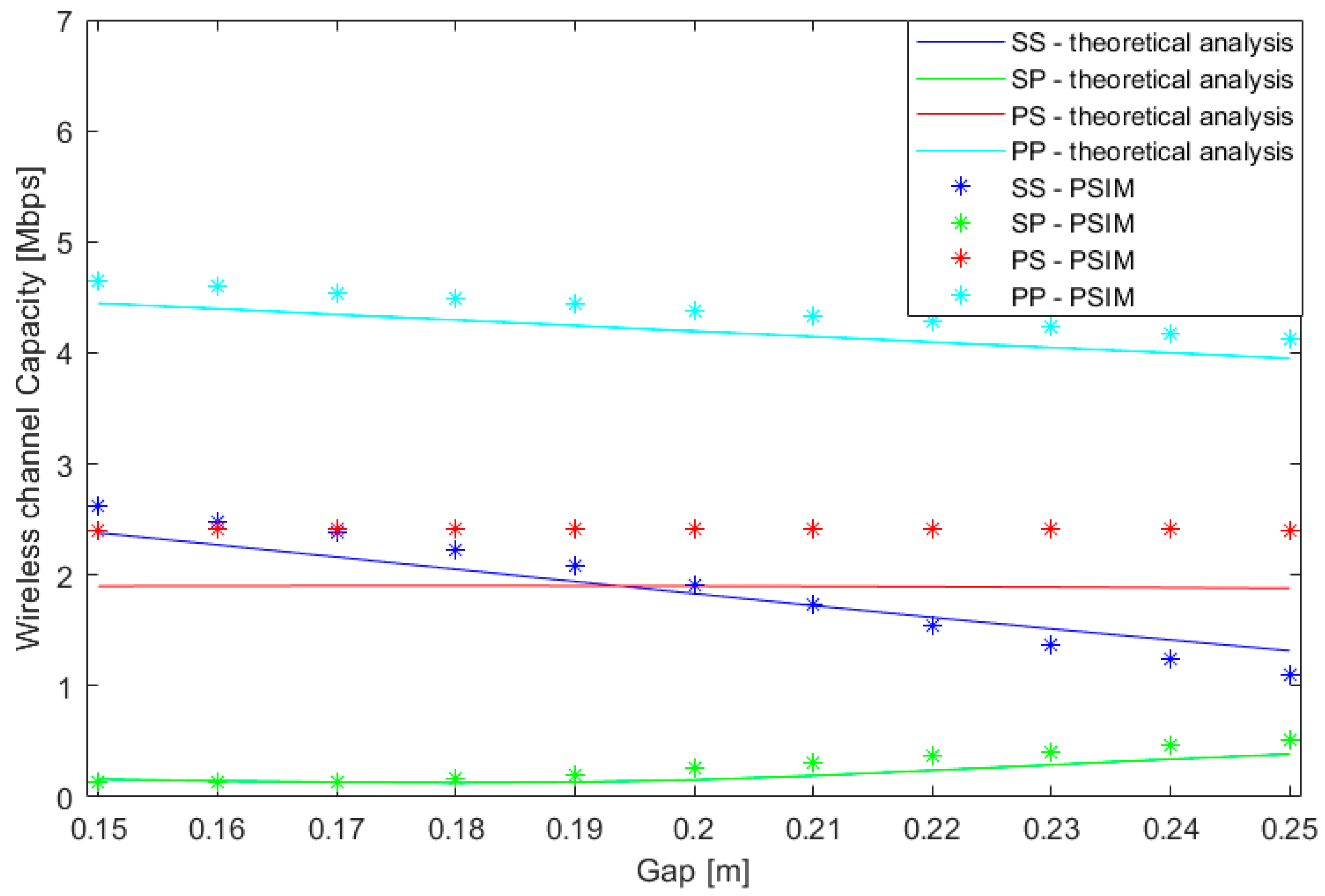
Figure 4, Figure 5 and Figure 6 show the results for each misalignment separately. The lines correspond to the numerical solution of the theoretical model exposed in Section 3. This was solved in a MATLAB (R2017b, Mathworks, Natick, MA, USA) environment. In contrast, the points represent the results obtained by simulations in PSIM. In particular, this tool simulates the electrical features of the four circuits under analysis. For the central frequency, 85 kHz, the root-mean-square value of the voltage is computed. Then, the frequency of the signal is manually varied in order to obtain the cutoff frequency, that is, the frequency at which the voltage at the load decreases by .
It can be observed that both solutions show the same type of variation with misalignment. However, it can be noticed that there some differences between the theoretical model and the simulation results. This is due to the fact that the two methods (theoretical model and PSIM) lead to approximated solutions. Firstly, in MATLAB we have developed a code to obtain the bandwidth in the theoretical model. In particular, the proposed method computes the cutoff-frequency as the one in which the power load divided by the load delivered at the operational frequency is between 0.48 and 0.52 W. The exact cutoff-frequency should be the one in which this ratio is 0.50, but extensive computation resources may be required for this determination. On the other hand, PSIM results are based on the root-mean-square computation of the voltage at the load. This parameter is affected by the transient period, so no exact solutions are derived from this tool either.
When a misalignment occurs, the separation between the coils is not the one assumed in the design process. This will affect the flux concatenated by both coils, which can be measured by . As a consequence, and and the corresponding channel capacity will change.
Observing the results, the first important conclusion is that the PP topology offers the highest communication capacity. This is due to the fact that this topology is the only one that is not working at the maximum power transfer. In the other three compensation topologies, at the operational frequency there is a peak in the power transfer to the load. Consequently, they are affected by the Q-factor imposed by the circuit. This reduces the bandwidth of the circuits and, in turn, the capacity of the wireless channel. In contrast, the PP compensation topology, even when designed according to [22], does not lead to a peak in the delivered power at 85 kHz. Thus, the diminution of the power delivered to the load is less severe if we compare it with the other ones. However, the power delivered to the load is significantly lower than in the other topologies.
The difference in the positions of the maximum frequencies at which the power delivered to the load is maximum is explained by the fact that the design goal in EV wireless chargers is to maximise the efficiency [24] and not the power transfer (as communication systems do).
On the other hand, the results demonstrate that the capacity of the wireless channel strongly varies with different relative positions between the coils for the Series–Series and the Parallel–Parallel compensation topologies. Specifically, for vertical misalignments, an increment in the gap of 5 cm leads to a 50% reduction in the capacity of the SS topology. This change implies nearly a 10% reduction in the channel capacity for the PP compensation network. Conversely, the variations in capacity due to vertical misalignments are much less severe for the Series–Parallel and Parallel–Series topologies.
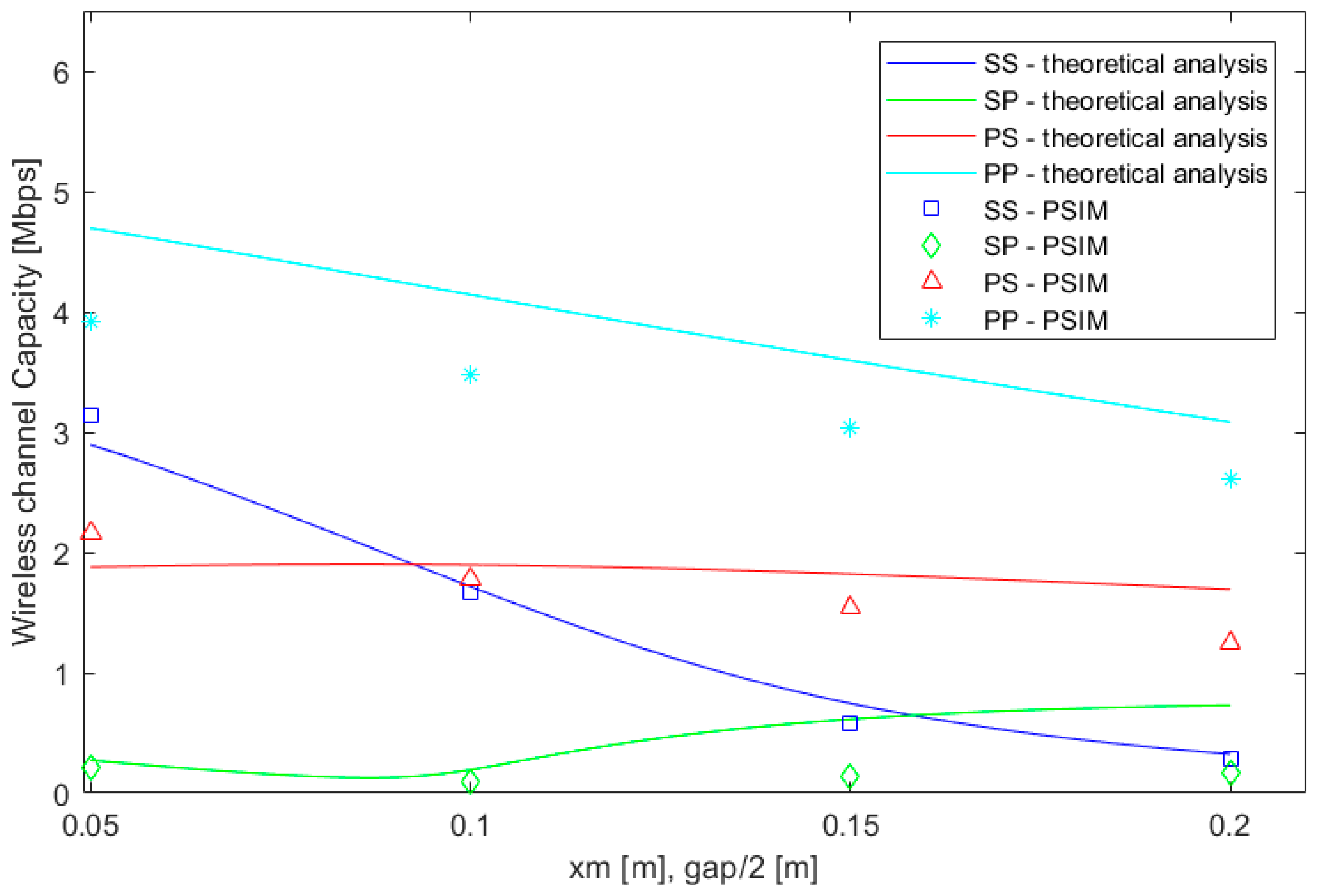
The communication capacity is less sensitive to horizontal misalignments. In Figure 5, it can be observed that the effects are practically unnoticeable when the misalignment parameter, , is less than 30 cm. For the joint vertical and horizontal misalignments, the effects are revealed with a shorter distance (), as the increase in the separation between the coils reduces the magnetic flux traversing the secondary coil earlier.
In conclusion, these results indicate that the communication channel capacity is more sensitive to vertical misalignment than to horizontal displacement. The variations in the channel capacity cannot be neglected, especially when symmetrical compensation networks are used in the charger. Consequently, the data rate of the source should be carefully selected and spread-spectrum techniques, such as the one proposed in [11], may not be suitable because of coil misalignment.
5. Conclusions
The inductive link offered by a wireless charger has been used in some recent papers as the communication channel for the transmission of data. This work has studied how the communication capacity of the wireless channel is altered by coil misalignments, which are typical in EV wireless chargers. We have formulated a theoretical model to analyse this impact for three types of coil misalignments and the four uni-resonant compensation topologies. The model has been contrasted with the simulation results of an EV wireless charger prototype. The theoretical model and the simulation results demonstrate that the capacity offered by the inductive link greatly depends on the coil displacements for the SS and PP topologies. In contrast, the asymmetrical topologies were shown to be less sensitive to these circumstances. Modulation information techniques should take into account this behavior in order to transmit data efficiently.
Acknowledgments
This work has been partially funded by José Castillejo Mobility Grant CAS 17-00318 of the Spanish Ministry of Education, Culture and Sports.
Author Contributions
The research problem addressed by the paper was identified by the three authors. Alicia Triviño-Cabrera proposed the methodology and conducted the simulation study. The simulation results were reviewed and analysed by the three authors. Alicia Triviño-Cabrera and Zhengyu Lin wrote the paper. José A. Aguado coordinate the complete work.
Conflicts of Interest
The authors declare no conflict of interest.
References
- Riehl, P.S.; Satyamoorthy, A.; Akram, H.; Yen, Y.-C.; Yang, J.-C.; Juan, B.; Lee, C.; Lin, F.; Muratov, V.; Plumb, W.; et al. Wireless Power Systems for Mobile Devices Supporting Inductive and Resonant Operating Modes. IEEE Trans. Microw. Theory Tech. 2015, 63, 780–790. [Google Scholar] [CrossRef]
- Kalwar, K.; Saad, M.; Mekhilef, A. Inductively coupled power transfer (ICPT) for electric vehicle charging—A review. Renew. Sustain. Energy Rev. 2015, 47, 462–475. [Google Scholar] [CrossRef]
- Wang, Z.; Wei, X. Design Considerations for Wireless Charging Systems with an Analysis of Batteries. Energies 2015, 8, 10664–10683. [Google Scholar] [CrossRef]
- Triviño-Cabrera, A.; Aguado, J.; González, J.M. Analytical characterisation of magnetic field generated by ICPT wireless charger. Electron. Lett. 2017, 53, 871–873. [Google Scholar] [CrossRef]
- Niyato, D.; Hoang, D.T.; Wang, P.; Han, Z. Cyber Insurance for Plug-In Electric Vehicle Charging in Vehicle-to-Grid Systems. IEEE Netw. 2017, 31, 38–46. [Google Scholar] [CrossRef]
- Shaukat, N.; Khan, B.; Ali, S.M.; Mehmood, C.A.; Khan, J.; Farid, U.; Majid, M.; Anwar, S.M.; Jawad, M.; Ullah, Z. A survey on electric vehicle transportation within smart grid system. Renew. Sustain. Energy Rev. 2018, 81, 1329–1349. [Google Scholar] [CrossRef]
- Zou, Y.; Zhu, J.; Wang, X.; Hanzo, L. A Survey on Wireless Security: Technical Challenges, Recent Advances, and Future Trends. Proc. IEEE 2016, 104, 1727–1765. [Google Scholar] [CrossRef]
- Wu, J.; Zhao, C.; Lin, Z.; Du, J.; Hu, Y.; He, X. Wireless Power and Data Transfer via a Common Inductive Link Using Frequency Division Multiplexing. IEEE Trans. Ind. Electron. 2015, 62, 7810–7820. [Google Scholar] [CrossRef]
- Sun, Y.; Yan, P.-X.; Wang, Z.-H.; Luan, Y.-Y. The Parallel Transmission of Power and Data with the Shared Channel for an Inductive Power Transfer System. IEEE Trans. Power Electron. 2016, 31, 5495–5502. [Google Scholar] [CrossRef]
- Huang, C.-C.; Lin, C.-L.; Wu, Y.-K. Simultaneous Wireless Power/Data Transfer for Electric Vehicle Charging. IEEE Trans. Ind. Electron. 2017, 64, 682–690. [Google Scholar] [CrossRef]
- De Angelis, A.; Carbone, P.; Sisinni, E.; Flammini, A. Performance Assessment of Chirp-Based Time Dissemination and Data Communications in Inductively Coupled Links. IEEE Trans. Instrum. Meas. 2017, 66, 1–9. [Google Scholar] [CrossRef]
- Huang, R.; Zhang, B. Frequency, Impedance Characteristics and HF Converters of Two-Coil and Four-Coil Wireless Power Transfer. IEEE J. Emerg. Sel. Top. Power Electron. 2015, 3, 177–183. [Google Scholar] [CrossRef]
- García-Vázquez, C.; Llorens-Iborra, F.; Fernández-Ramírez, L.; Sánchez-Sain, H.; Jurado, F. Comparative study of dynamic wireless charging of electric vehicles in motorway, highway and urban stretches. Energy 2017, 137, 42–57. [Google Scholar] [CrossRef]
- Sampath, J.P.K.; Alphones, A.; Vilathgamuwa, D.M. Figure of Merit for the Optimization of Wireless Power Transfer System against Misalignment Tolerance. IEEE Trans. Power Electron. 2017, 32, 4359–4369. [Google Scholar] [CrossRef]
- Lee, K.; Cho, D.-H. Maximizing the Capacity of Magnetic Induction Communication for Embedded Sensor Networks in Strongly and Loosely Coupled Regions. IEEE Trans. Magn. 2013, 49, 5055–5062. [Google Scholar] [CrossRef]
- Gulbahar, B. A Communication Theoretical Analysis of Multiple-Access Channel Capacity in Magneto-Inductive Wireless Networks. IEEE Trans. Commun. 2017, 65, 2594–2607. [Google Scholar] [CrossRef]
- Azad, U.; Jing, H.C.; Wang, Y.E. Link Budget and Capacity Performance of Inductively Coupled Resonant Loops. IEEE Trans. Antennas Propag. 2012, 60, 2453–2461. [Google Scholar] [CrossRef]
- Ortego-Isasa, I.; Benli, K.P.; Casado, F.; Sancho, J.I.; Valderas, D. Topology Analysis of Wireless Power Transfer Systems Manufactured Via Inkjet Printing Technology. IEEE Trans. Ind. Electron. 2017, 64, 7749–7757. [Google Scholar] [CrossRef]
- Zhang, W.; Mi, C.C. Compensation Topologies of High-Power Wireless Power Transfer Systems. IEEE Trans. Veh. Technol. 2016, 65, 4768–4778. [Google Scholar] [CrossRef]
- Jiang, C.; Chau, K.T.; Liu, C.; Lee, C.H.T. An Overview of Resonant Circuits for Wireless Power Transfer. Energies 2017, 10, 894. [Google Scholar] [CrossRef]
- Lu, X.; Wang, P.; Niyato, D.; Kim, D.I.; Han, Z. Wireless Charging Technologies: Fundamentals, Standards, and Network Applications. IEEE Commun. Surv. Tutor. 2016, 18, 1413–1452. [Google Scholar] [CrossRef]
- Wang, C.-S.; Covic, G.A.; Stielau, O.H. Power Transfer Capability and Bifurcation Phenomena of Loosely Coupled Inductive Power Transfer Systems. IEEE Trans. Ind. Electron. 2004, 51, 148–157. [Google Scholar] [CrossRef]
- Villa, J.L.; Sallan, J.; Osorio, J.F.S.; Llombart, A. High-Misalignment Tolerant Compensation Topology for ICPT Systems. IEEE Trans. Ind. Electron. 2012, 59, 945–951. [Google Scholar] [CrossRef]
- Xiao, C.; Liu, Y.; Cheng, D.; Wei, K. New Insight of Maximum Transferred Power by Matching Capacitance of a Wireless Power Transfer System. Energies 2017, 10, 688. [Google Scholar]
- Dehui, W.; Qisheng, S.; Xiaohong, W.; Fan, Y. Analytical Model of Mutual Coupling between Rectangular Spiral Coils with Lateral Misalignment for Wireless Power Applications. Available online: http://digital-library.theiet.org/content/journals/10.1049/iet-pel.2017.0470 (accessed on 28 February 2018).
- Joy, E.R.; Dalal, A.; Kumar, P. Accurate Computation of Mutual Inductance of Two Air Core Square Coils with Lateral and Angular Misalignments in a Flat Planar Surface. IEEE Trans. Magn. 2014, 50, 1–9. [Google Scholar] [CrossRef]
Figure 1.
Structure of an Inductively Coupled Power Transfer (ICPT) wireless charger for electric vehicles (EV).
Figure 1.
Structure of an Inductively Coupled Power Transfer (ICPT) wireless charger for electric vehicles (EV).

Figure 2.
Equivalent circuit of an ICPT system.

Figure 3.
Illustration of the types of coil misalignments that may occur in an EV wireless charger: (a) vertical misalignment; (b) horizontal misalignment; (c) vertical and horizontal misalignment.
Figure 3.
Illustration of the types of coil misalignments that may occur in an EV wireless charger: (a) vertical misalignment; (b) horizontal misalignment; (c) vertical and horizontal misalignment.

Figure 4.
Variations in the wireless channel capacity due to vertical misalignments. SS, Series–Series; SP, Series–Parallel; PP, Parallel–Parallel; PS, Parallel–Series; PSIM (Power Simulation Technology).
Figure 4.
Variations in the wireless channel capacity due to vertical misalignments. SS, Series–Series; SP, Series–Parallel; PP, Parallel–Parallel; PS, Parallel–Series; PSIM (Power Simulation Technology).

Figure 5.
Variations in the wireless channel capacity due to horizontal misalignments.
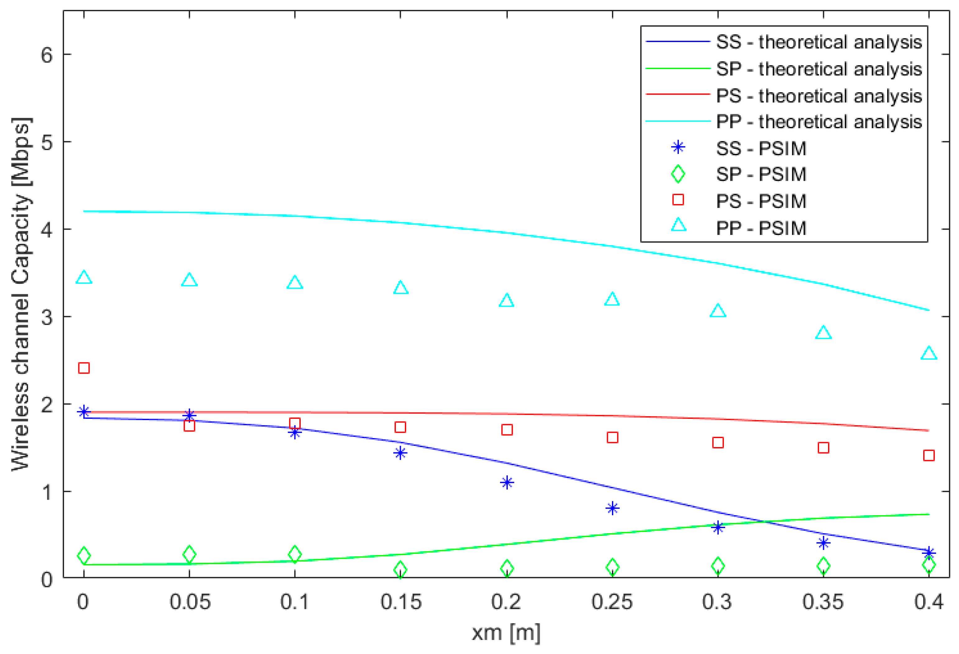
Figure 6.
Variations in the wireless channel capacity due to vertical and horizontal misalignments.

Table 1.
Values of the capacitors in the single-resonant compensation topologies.
| Topology | ||
|---|---|---|
| Series–Series | ||
| Series–Parallel | ||
| Parallel–Series | ||
| Parallel–Parallel |
Table 2.
Characteristics of the EV wireless charger.
| Parameter | Value |
|---|---|
| Output | 3.7 kW @ 300 V |
| f [kHz] | 85 |
| N1 [number of turns in the primary coil] | 11 |
| N2 [number of turns in the secondary coil] | 14 |
| a1 × b1 [m2] | 0.75 × 0.75 |
| a2 × b2 [m2] | 0.5 × 0.5 |
| gd [m] | 0.2 |
| L1 [µH] | 240.5 |
| L2 [µH] | 230.6 |
| R1 [mΩ] | 196 |
| R2 [mΩ] | 143 |
| Rb [Ω] | 30 |
| C2 [nF] | 15.20 |
| C1 [nF] @ SS | 14.57 |
| C1 [nF] @ SP | 15.02 |
| C1 [nF] @ PS | 15.02 |
| C1 [nF] @ PP | 14.36 |
| M [µH] @ gap = 15 cm, xm = 0 cm | 49.78 |
| M [µH] @ gap = 20 cm, xm = 0 cm | 40.8 |
| M [µH] @ gap = 25 cm, xm = 0 cm | 33.38 |
| M [µH] @ xm = 5 cm, gap = gd | 40.39 |
| M [µH] @ xm = 10 cm, gap = gd | 39.07 |
| M [µH] @ xm = 15 cm, gap = gd | 36.72 |
| M [µH] @ xm = 5 cm, gap = 10 cm | 59.9 |
| M [µH] @ xm = 10 cm, gap = 20 cm | 39.07 |
© 2018 by the authors. Licensee MDPI, Basel, Switzerland. This article is an open access article distributed under the terms and conditions of the Creative Commons Attribution (CC BY) license (http://creativecommons.org/licenses/by/4.0/).
Share and Cite
MDPI and ACS Style
Triviño-Cabrera, A.; Lin, Z.; Aguado, J.A. Impact of Coil Misalignment in Data Transmission over the Inductive Link of an EV Wireless Charger. Energies 2018, 11, 538. https://doi.org/10.3390/en11030538
AMA Style
Triviño-Cabrera A, Lin Z, Aguado JA. Impact of Coil Misalignment in Data Transmission over the Inductive Link of an EV Wireless Charger. Energies. 2018; 11(3):538. https://doi.org/10.3390/en11030538
Chicago/Turabian StyleTriviño-Cabrera, Alicia, Zhengyu Lin, and José A. Aguado. 2018. "Impact of Coil Misalignment in Data Transmission over the Inductive Link of an EV Wireless Charger" Energies 11, no. 3: 538. https://doi.org/10.3390/en11030538
Note that from the first issue of 2016, this journal uses article numbers instead of page numbers. See further details here.