Modeling and Experimentation of New Thermoelectric Cooler–Thermoelectric Generator Module


1
Laboratory of Low Emission Vehicle, Beijing Institute of Technology, Beijing 100081, China
2
Algerian Space Agency, Algiers 16000, Algeria
3
Laboratory of Power Machinery and Engineering, Beijing Institute of Technology, Beijing 100081, China
*
Author to whom correspondence should be addressed.
Energies 2018, 11(3), 576; https://doi.org/10.3390/en11030576
Submission received: 23 January 2018
/
Revised: 1 March 2018
/
Accepted: 2 March 2018
/
Published: 7 March 2018
(This article belongs to the Special Issue Emerging Power Electronics Technologies for Power Systems and Machine Drives)
Abstract
:In this work, a modeling and experimental study of a new thermoelectric cooler–thermoelectric generator (TEC-TEG) module is investigated. The studied module is composed of TEC, TEG and total system heatsink, all connected thermally in series. An input voltage (1–5 V) passes through the TEC where the electrons by means of Peltier effect entrain the heat from the upper side of the module to the lower one creating temperature difference; TEG plays the role of a partial heatsink for the TEC by transferring this waste heat to the total system heatsink and converting an amount of this heat into electricity by a phenomenon called Seebeck effect, of the thermoelectric modules. The performance of the TEG as partial heatsink of TEC at different input voltages is demonstrated theoretically using the modeling software COMSOL Multiphysics. Moreover, the experiment validates the simulation result which smooths the path for a new manufacturing thermoelectric cascade model for the cooling and the immediate electric power generation.
1. Introduction
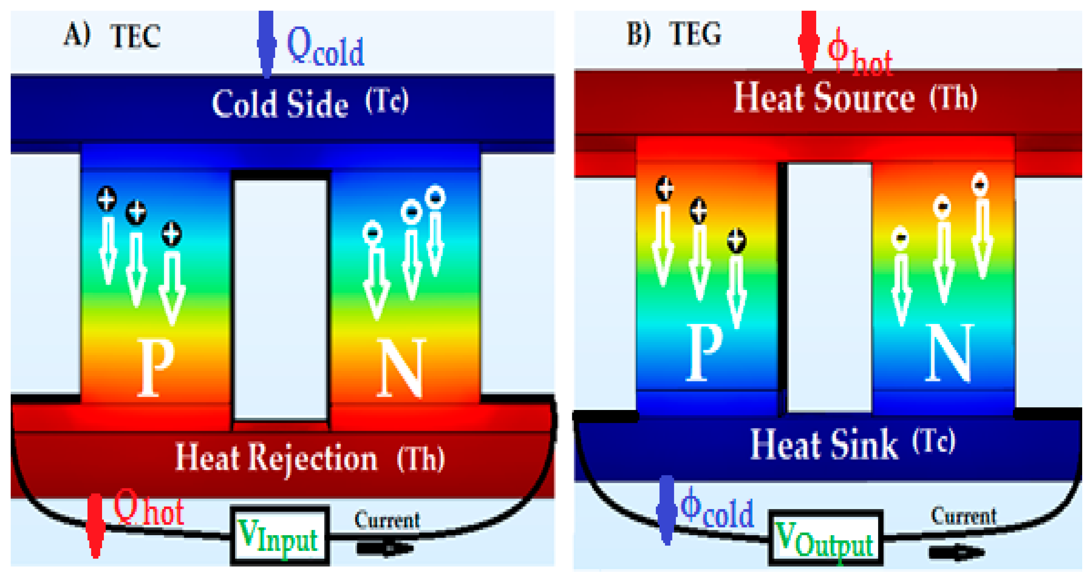
Due to the necessity of cooling in several fields such as electronics [1,2,3,4], automotive [5], and photovoltaic [6,7], thermoelectric coolers (TEC) have become widespread in the last decades. Thermoelectric coolers contain a number (N) of n-p thermoelectric doped couples made of semiconductor material inserted between two thermally conducting and electrically insulating ceramic plates [7]. The conversion efficiency of thermoelectric materials is governed by a dimensionless factor called the figure of merit (ZT), which is defined as , where S,, T and k are Seebeck coefficient, electrical conductivity, operating temperature and the thermal conductivity of the material, respectively [8]. Practically, when direct current flows from n-type material to p-type material in a TEC, it provokes a heat transfer from a side called the cold side with a temperature Tcold, to the other side known as the hot side of the device with a temperature Thot, where the absorbed heat from the cold side and the rejected heat at the hot side are, respectively, Qcold and Qhot, as shown in Figure 1A. This phenomenon is called the Peltier effect [9]. The cooling efficiency of the thermoelectric coolers is also known as the coefficient of performance (COP) and governed by Equation (1) with (Tave = (Tcold + Thot)/2) as follows [8]:
Oppositely to Peltier effect, the thermoelectric generator (TEG) produces electric energy by means of Seebeck effect, via applying temperature gradient (ΔT) on the cold (Tcold) and hot side (Thot) of the module [6,7,10]. Figure 1B describes the working principle of TEG. Similar to TEC, TEG is a compact device with a noiseless simple design that has no moving organs [11]; it has been used generally in the industry as waste heat remedy [9], in vehicles [5,6,7,8,9,10], buildings (houses, restaurants, etc.), and concentrated photovoltaic systems [12,13,14]. The electric power generation efficiency of the thermoelectric generators is governed by Equation (2) as follows [8]:
The efficiency of thermoelectric generators and the coefficient of performance of thermoelectric coolers are the major challenges of the thermoelectric modules, which is why some research [15,16,17] has been carried out to expand the thermoelectric materials figure of merit (ZT) by maximizing Seebeck coefficient S [18,19] and the electric conductivity σ, minimizing the thermal conductivity k [20,21] of thermoelectric materials, and diminishing the manufacturing cost of the TEM [22,23]. However, remarkable progress has been made in the last decades in thermoelectric field since the first encounter of Seebeck effect; therefore, we can divide thermoelectric materials based on the figure of merit value into three generations [8]. The first generation is from 1960 to 1990 for the materials with a figure of merit value of about (ZT = 1.0) and a maximum efficiency of 5% [24,25]. The second generation proceeded until 2010, during which the efficiency value is about 11–15% with ZT value of about 1.8 [26]. The third generation includes research on new approaches and different concepts thet have been carried since 2010 until now, on bulk thermoelectric to enlarge the figure of merit to ZT ≥ 2.0 with efficiency reaching 20% [27].
In this paper, we have combined equally, the cooling capability and electrical energy generation of thermoelectric materials to fit into one module. Furthermore, our module consists of two components, TEC and TEG. TEC is used for cooling by transferring the heat from its cold side to the hot side by means of Seebeck effect; TEG plays the role of a remedy device by converting the waste heat of the hot side of TEC into electrical energy by means of Peltier effect. The combination of thermoelectric coolers and thermoelectric generators is novel and such module has been used in the photovoltaic application under different sun concentration ratio in a previous study [7]. Modeling and finite element method is used to examine the cooling behavior and the electrical power generation of TEC-TEG module at different electrical potential using COMSOL Multiphysics software.
2. Modeling and Experimentations
2.1. COMSOL Finite Element Model
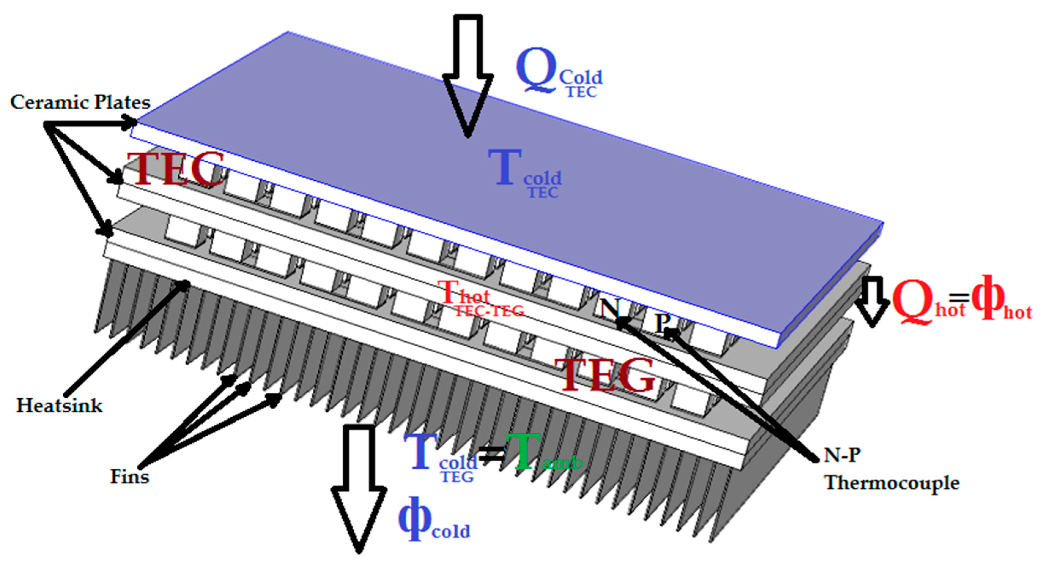
The design of the TEC-TEG module using COMSOL Multiphysics software (COMSOL Group, version 5.2.0.220, Stockholm, Sweden) is shown in Figure 2. Theoretically, an external direct electrical potential (1–5 V) passes through the proposed thermally insulated module (except the TEG’s cold side (lower side) which is kept at ambient temperature Tcold (TEG) = Tamb) for the purpose of studying the cooling ability of TEC. A heat flow Qcold (TEC) is absorbed from the upper side of TEC and transferred to the contact point of the two modules where is located the highest temperature of the system Thot (TEC-TEG) = Tmax. However, as the cooling capacity and power generation of thermoelectric modules depend on the temperature difference between the module sides, TEG will be a remedy device of the TEC, by converting a portion of its waste heat Qhot into electric power. The materials properties used for simulation and design parameters are in Table 1 and Table 2, respectively; the value of Seebeck coefficient, electrical conductivity and thermal conductivity can be found in Reference [7].
The steady state finite element model computes the temperature and the electric potential values corresponding to spatial coordinates only; the governing equations that analyze the thermoelectric device behavior are the heat flow described in Equation (3), and the continuity of electric charge in Equation (4) [28], where both are coupled by constitutive Equations (5) and (6) as follow:
where , C, T, t, , , , , , , , and are the density, specific heat capacity, absolute temperature, time, heat generation rate per unit of volume, heat flux vector, electric current intensity vector, electric field intensity vector, electric permittivity matrix, Peltier coefficient matrix, thermal conductivity matrix, electric conductivity matrix, and Seebeck coefficient matrix, respectively.
The electric field can be derived from an electric scalar potential φ, as shown in Equation (7):
Under a steady state condition and by substituting Equations (5)–(7) into Equations (3) and (4), we get the thermoelectric system Equations (8) and (9), where they can be transformed into finite element equations to solve the temperature T and the electric potential :
To get the emitted heat from the hot side Qhot, and the absorbed heat at the cold side Qcold by TEC device, Equations (10) and (11) are the differential equations solution at the junction, in which S, Tcold, Thot, ITEC, RTEC, and kTEC, are Seebeck coefficient of the module, cold and hot side temperature, electric current, total electric resistance, thermal conductivity of the TEC module, correspondently.
The heat input фhot and output фcold of TEG are determined by Equations (12) and (13), where kTEG, RTEG and ITEG are, respectively, the thermal conductivity, total resistance, and generated current of the thermoelectric generator module:
2.2. Experimental Settlement
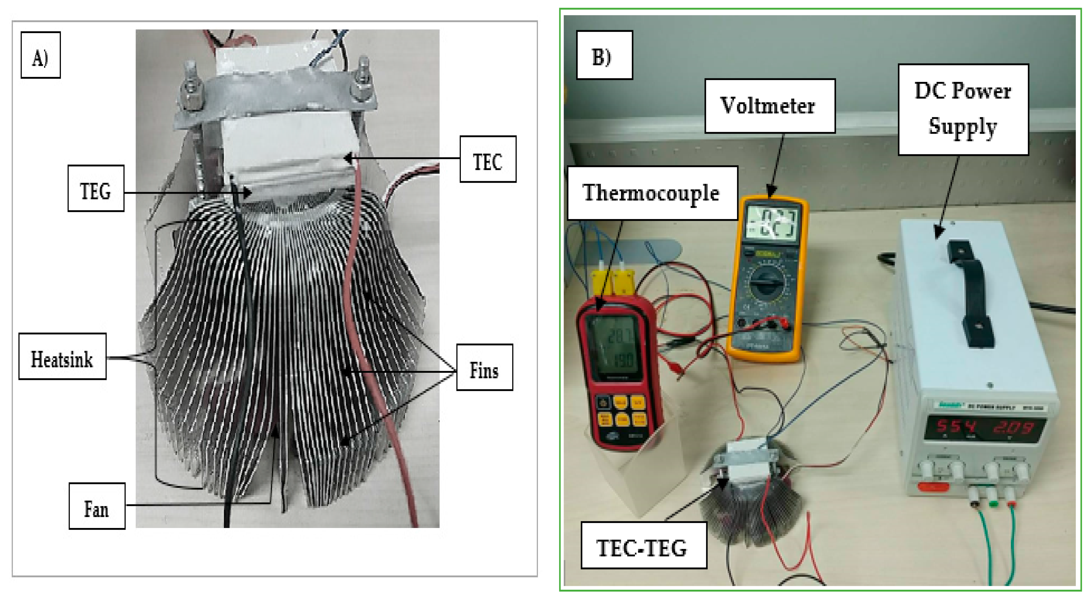
In experimentation, the system is based on Figure 3 and governed by Equations (3)–(13). The TEC-TEG module is well illustrated in Figure 3A and the whole system with the measuring equipment in Figure 3B. Furthermore, a CP12706 TEC (Hebei IT, Shanghai, China) module with dimensions (40 × 40 × 3.92 mm³) and internal resistance of 2.07 Ω, is settled at different voltages value (1–5 V), to examine the cooling behavior by measuring the temperature Tcold(TEC) on the cold side in every case.
A Thermocouple of K type (Thermometer GM1312 made by BENETECH company, Shenzhen, China) is used for that purpose and similarly to measure the temperature value Thot (TEC-TEG) at the contact point between the TEC and TEG.
TEC is connected thermally in series with TEG, as shown in Figure 3. However, the TEG used is also a CP12706 model with the same dimensions and parameters, but used for the electric power generation purpose. In addition, the thermoelectric generator is connected to a copper heatsink with a temperature (Theatsink) for the aim of cooling the whole TEC-TEG module (Heatsink temperature it is constant and equal to 301 K.
3. Simulation and Experimental Results
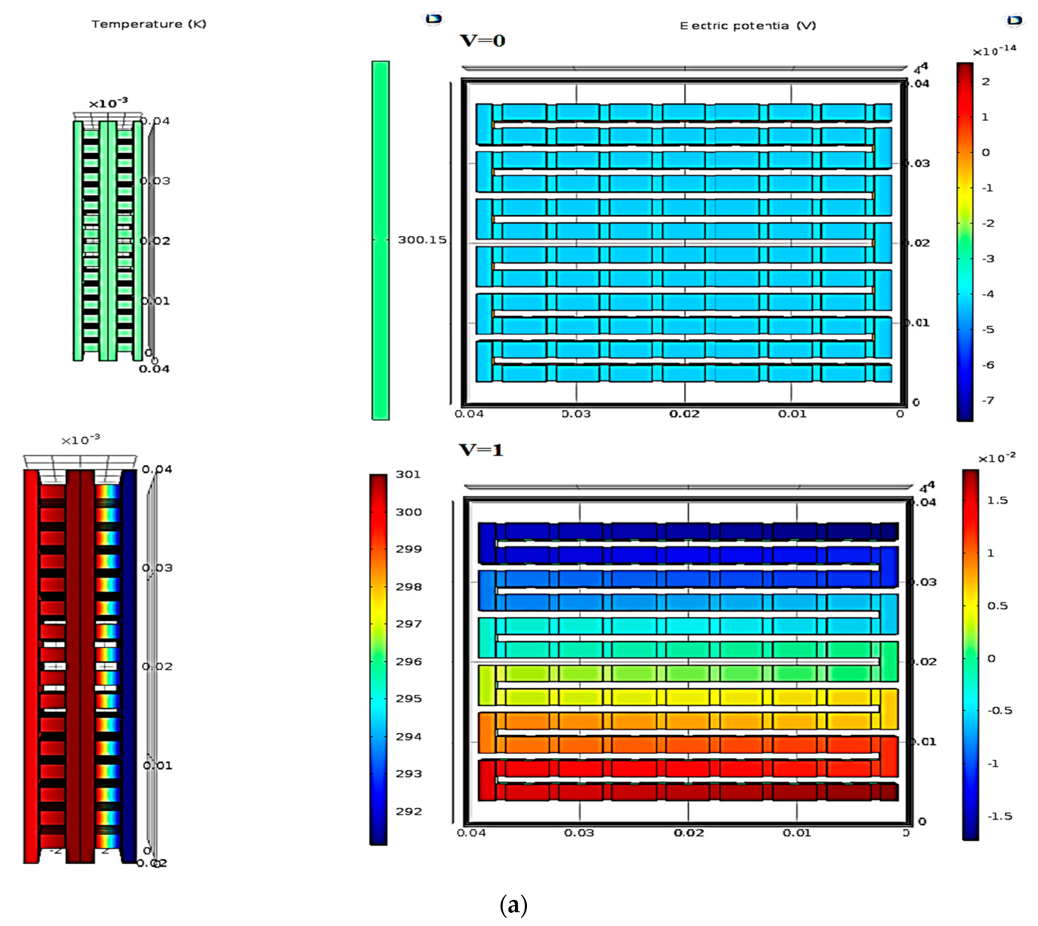
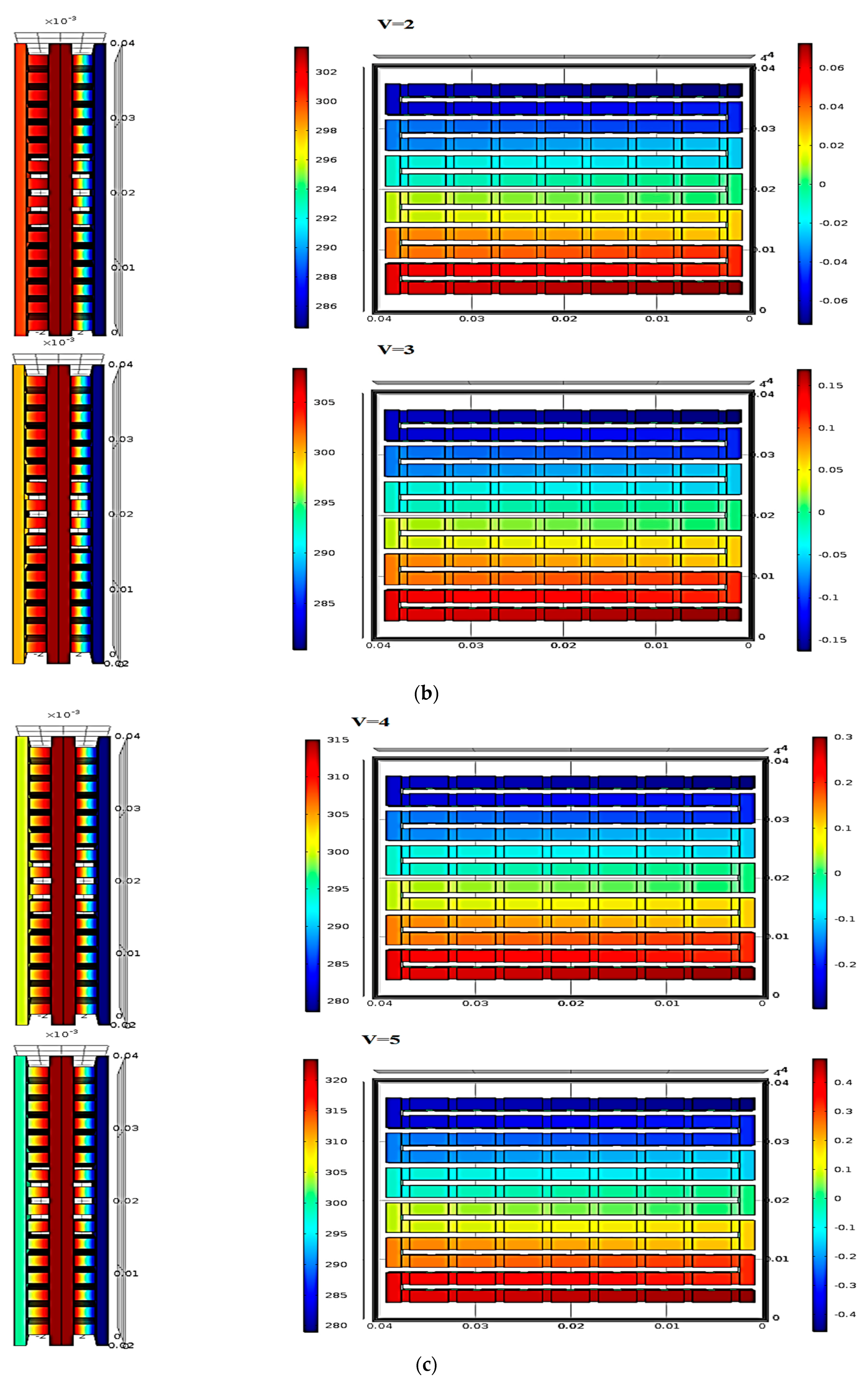
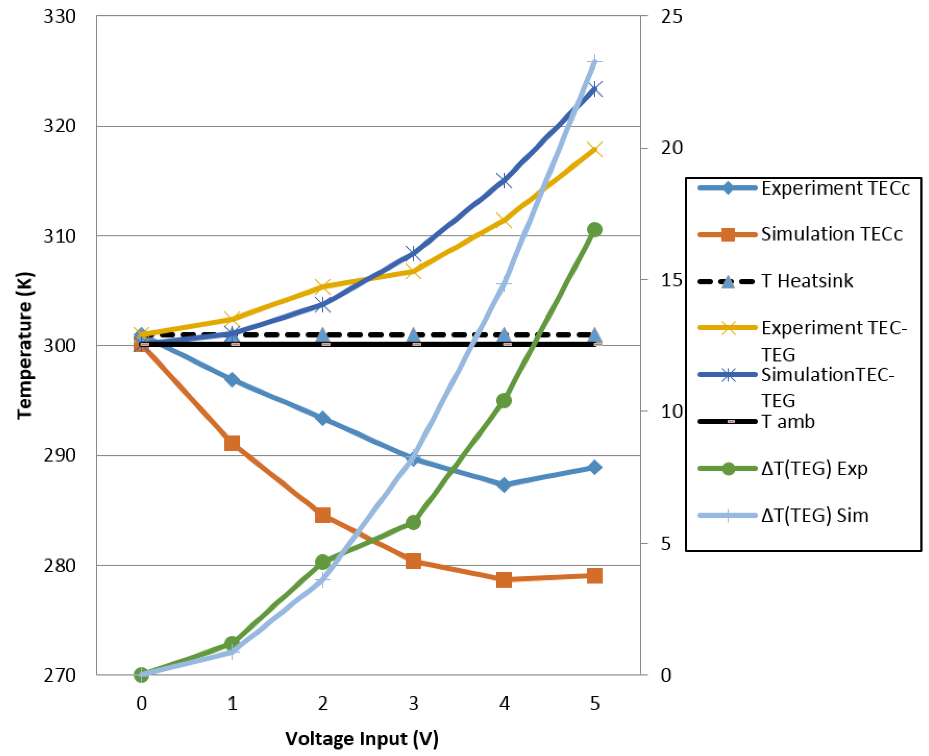
The experimental and simulation results of TEC’s cold side temperature at different voltages input (1–5 V) is shown in Figure 5. The graph shows the cooling behavior of the module at different electric voltage input; as expected the temperature of the cold side of TEC decreases in simulation, from the ambient temperature (Tamb = 300.15 K) to 291.11 K at an input voltage equal to 1 V. The TEC cold side temperature decreases dramatically reaching its lowest temperature, which equals to 278.63 K at 4 V. Because of overheating due to the intensification of Joule heat, a slight increase in temperature reaching 279 K at input voltage of 5 V is noticed. (The COMSOL Multiphysics simulation results of the temperature contours of TEC-TEG module at every TEC’s voltage input (1–5 V) is shown in Figure 4).
However, the experiment validates the simulation results where TEC’s cold side temperature decreases from the ambient temperature (301 K) to 296.9 K at input voltage equals to 1 V. Besides, the TEC’s cold side temperature decreases continually to reach the lowest temperature value of 287.3 K at input voltage of 4 V, but it increases again at input voltage of 5 V reaching 288.9 K.
Figure 5 shows the influence of the input voltage of TEC on the temperature difference between the cold and hot side of TEG (∆T) in both simulation and experiment. The temperature difference ∆T is directly proportional to the TEC’s input voltages, where it increases in simulation from 0 K at 0 V to 0.88 K at 1 V and reaches a maximum of 16.9 K at voltage input equal to 5 V. Similar to simulation, the temperature difference ∆T increases from 0 K at input voltage of 0 V to reach the maximum of 23.27 K at 5 V input voltage in the experiment. Slight difference in simulation and experimental results is noticed, due to predefined geometrical parameters and material properties used for simulation and the module used for experiment.
Figure 4 describes, at different voltages input, the temperature propagation from the cold side of the thermoelectric cooler to the hot side of the thermoelectric generator, and from this latter side to the heatsink which is maintained at ambient temperature (Tamb = 300.15 K). The current flows through TEC at voltage input of 1 V, transfers an amount of heat from its cold side to the contact side of TEC and TEG and increases its temperature to 301.03 K. With increasing the input voltage of TEC to be 2 V, 3 V, 4 V and 5 V, the TEC-TEG contact side temperature increases to about 303.76 K, 308.41 K, 315 K and 323.42 K, respectively.
Figure 5 shows simulation and experimental results comparison of TEC-TEG contact side temperature at different TEC’s voltages input results. Moreover, the temperature at TEC-TEG contact side is proportional to the input voltage in both simulation and experiment. From an input voltage of 0 V to 1 V, 2 V, 3 V, 4 V and 5 V, the temperature increases from 301 K to 302.40 K, 305.3 K, 306.8 K, 311.4 K and 317.90 K, respectively.
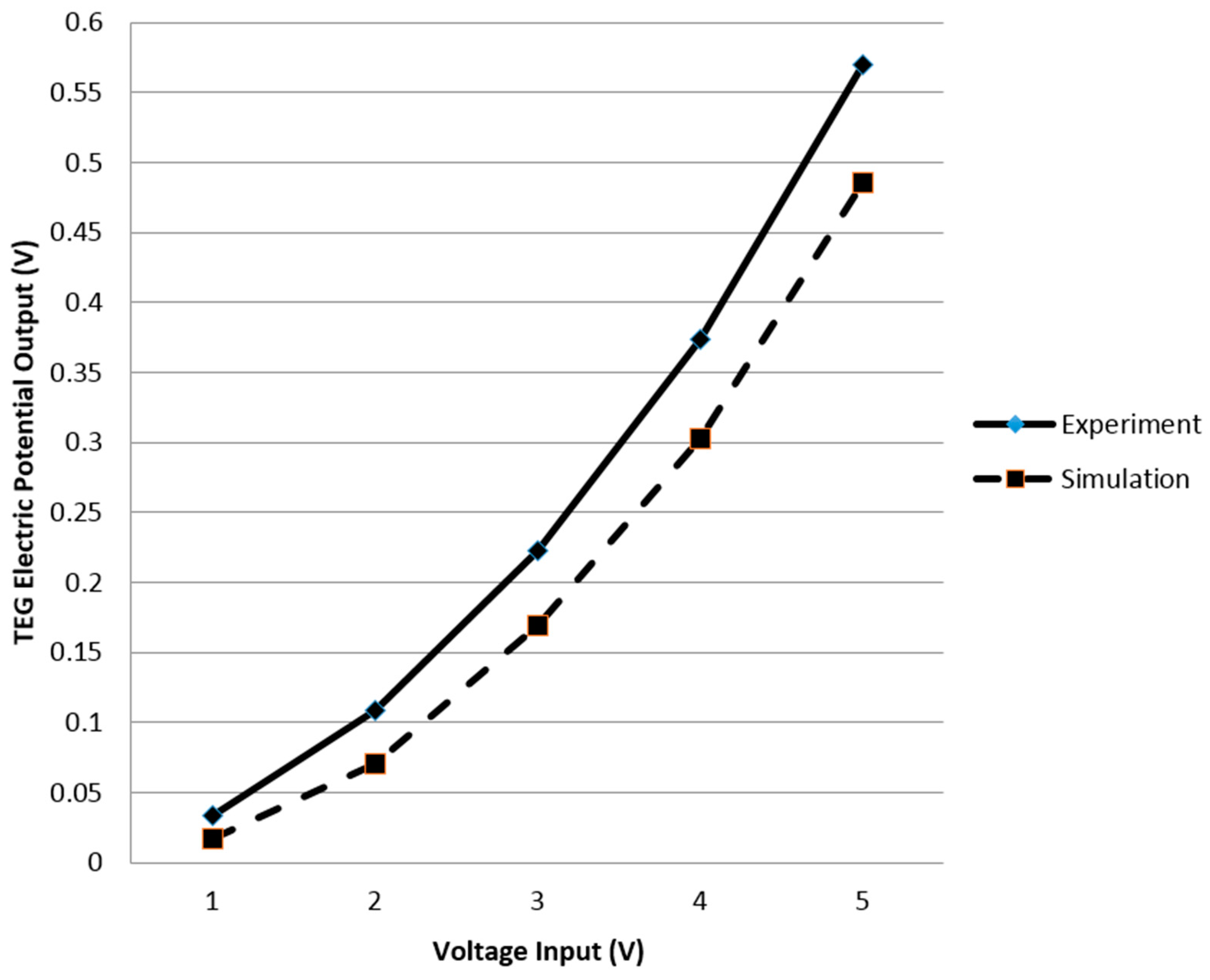
Results of TEG potential generated in simulation are shown in Figure 4 where the generated potential of thermoelectric generated is equal to 0 V at input voltage of 0 V (no electric potential generated). By increasing the TEC’s voltage input to 1 V, 2 V, 3 V, 4 V and 5 V, the electric potential generated by TEG increases reaching values of about 0.02 V, 0.07 V, 0.17 V, 0.30 V and a maximum of 0.50 V, respectively. Figure 6 shows the comparison between the electric potential generated by TEG at different TEC input voltages without load in simulation and experiment. TEG potential output is directly proportional to TEC’s input voltage in both, simulation and experiment; therefore, the obtained results of the TEG electric potential generated in experiment are similar to the one of simulation. Moreover, TEG electric potential generated at input voltage of 1 V in experiment is equal to 0.03 V and it increases at input voltage of TEC of 2 V, 3 V, 4 V and 5 V to about 0.11 V, 0.22 V, 0.4 V and a maximum of 0.60 V. Slight difference between simulation and experiment result is noticed because of the experimental conditions and the simulation boundary conditions.
4. Conclusions
Thermoelectric devices are environmentally friendly for either power generation or cooling purposes; therefore, in this work, TEC-TEG module was investigated via simulation and experiment. Our module contains TEC, TEG and total copper heatsink attached thermally in series; the cooling behavior of TEC and TEG’s electric power generation is examined. The electrical potential generation of TEG increases with increasing the voltage input of TEC to reach about 0.5 V at an input voltage of 5 V. Furthermore, when direct electric current passes through TEC, it transfers an amount of heat from the cold side to the hot side of the module, where the cold side of the thermoelectric cooler reaches a minimum temperature of 278.63 K and 287.3 K in simulation and experiment, respectively, at TEC’s input voltage of 4 V. Moreover, results in this study show the influence of the TEC’s input voltage on the temperature difference between the hot and cold side of the TEG which is important to maximize the electric potential generated by the TEG. The temperature difference between TEG’s sides is directly proportional to the TEC’s input voltages where the maximum temperature difference is about 17 K and 23 K at an input voltage of 5 V in experiment and simulation, respectively. Design and results of this work show the significance of using thermoelectric generators as partial heatsink and remedy device for thermoelectric coolers, even without an additional external thermal load. This study paves the way for new thermoelectric modules that can be directed to manufacturing for both cooling and electric power generation.
Acknowledgments
This work was supported by Laboratory of Low Emission Vehicle of Beijing Institute of Technology, Beijing, China; and the Algerian Space Agency, Algeria.
Author Contributions
All authors contributed to this work. Khaled Teffah carried out the modeling and calculations. Xiao-long Mou and Khaled Teffah provided the original idea and analyzed the simulation results. Youtong Zhang and Khaled Teffah supplied the original data of case study and revised the manuscript. All authors have read and approved the final manuscript.
Conflicts of Interest
The authors declare no conflict of interest.
References
- Mahajan, R.; Chiu, C.-P.; Chrysler, G. Cooling a microprocessor chip. Proc. IEEE 2006, 94, 1476–1486. [Google Scholar] [CrossRef]
- Prasher, R.S.; Chang, J.-Y.; Sauciuc, I.; Narasimhan, S.; Chau, D.; Chrysler, G.; Myers, A.; Prstic, S.; Hu, C. Nano and Micro Technology-Based Next-Generation Package-Level Cooling Solutions. Intel Technol. J. 2005, 9, 285–296. [Google Scholar] [CrossRef]
- Simons, R.; Chu, R. Application of thermoelectric cooling to electronic equipment: A review and analysis. In Proceedings of the Sixteenth Annual IEEE Semiconductor Thermal Measurement and Management Symposium, San Jose, CA, USA, 23 March 2000; pp. 1–9. [Google Scholar]
- Abramzon, B. Numerical Optimization of the Thermoelectric Cooling Systems. In Proceedings of the 9th AIAA/ASME Joint Thermophysics and Heat Transfer Conference, Fluid Dynamics and Co-located Conferences, San Francisco, CA, USA, 5–8 June 2006; p. 3414. [Google Scholar] [CrossRef]
- Yang, J.; Stabler, F.R. Automotive applications of thermoelectric materials. J. Electron. Mater. 2009, 38, 1245–1251. [Google Scholar]
- Lamba, R.; Kaushik, S. Modeling and performance analysis of a concentrated photovoltaic–thermoelectric hybrid power generation system. Energy Convers. Manag. 2016, 115, 288–298. [Google Scholar] [CrossRef]
- Teffah, K.; Zhang, Y. Modeling and experimental research of hybrid PV-thermoelectric system for high concentrated solar energy conversion. Sol. Energy 2017, 157, 10–19. [Google Scholar]
- Zhang, X.; Zhao, L.-D. Thermoelectric materials: Energy conversion between heat and electricity. J. Materiom. 2015, 1, 92–105. [Google Scholar] [CrossRef]
- Riffat, S.B.; Ma, X. Thermoelectrics: A review of present and potential applications. Appl. Therm. Eng. 2003, 23, 913–935. [Google Scholar] [CrossRef]
- Kiflemariam, R.; Lin, C.-X.; Moosavi, R. Numerical simulation, parametric study and optimization of thermoelectric generators for self-cooling of devices. In Proceedings of the 11th AIAA/ASME Joint Thermophysics and Heat Transfer Conference, Atlanta, GA, USA, 16–20 June 2014; American Institute of Aeronautics and Astronautics: Reston, VA, USA, 2014. [Google Scholar]
- Zhang, Z.; Qiu, J.; Wang, S. Roll-to-roll printing of flexible thin-film organic thermoelectric devices. Manuf. Lett. 2016, 8, 6–10. [Google Scholar]
- Chávez-Urbiola, E.; Vorobiev, Y.V.; Bulat, L. Solar hybrid systems with thermoelectric generators. Sol. Energy 2012, 86, 369–378. [Google Scholar] [CrossRef]
- Beeri, O.; Rotem, O.; Hazan, E.; Katz, E.A.; Braun, A.; Gelbstein, Y. Hybrid photovoltaic-thermoelectric system for concentrated solar energy conversion: Experimental realization and modeling. J. Appl. Phys. 2015, 118, 115104. [Google Scholar] [CrossRef]
- Benghanem, M.; Al-Mashraqi, A.; Daffallah, K. Performance of solar cells using thermoelectric module in hot sites. Renew. Energy 2016, 89, 51–59. [Google Scholar] [CrossRef]
- Majumdar, A. Thermoelectricity in semiconductor nanostructures. Science 2004, 303, 777–778. [Google Scholar] [CrossRef] [PubMed]
- Shakouri, A. Nanoscale thermal transport and microrefrigerators on a chip. Proc. IEEE 2006, 94, 1613–1638. [Google Scholar] [CrossRef]
- Poudel, B.; Hao, Q.; Ma, Y.; Lan, Y.; Minnich, A.; Yu, B.; Yan, X.; Wang, D.; Muto, A.; Vashaee, D.; et al. High-thermoelectric performance of nanostructured bismuth antimony telluride bulk alloys. Science 2008, 320, 634–638. [Google Scholar] [CrossRef] [PubMed]
- Heremans, J.P.; Jovovic, V.; Toberer, E.S.; Saramat, A.; Kurosaki, K.; Charoenphakdee, A.; Yamanaka, S.; Snyder, G.J. Enhancement of thermoelectric efficiency in PbTe by distortion of the electronic density of states. Science 2008, 321, 554–557. [Google Scholar] [CrossRef] [PubMed]
- Heremans, J.P.; Wiendlocha, B.; Chamoire, A.M. Resonant levels in bulk thermoelectric semiconductors. Energy Environ. Sci. 2012, 5, 5510–5530. [Google Scholar] [CrossRef]
- Lan, Y.; Minnich, A.J.; Chen, G.; Ren, Z. Enhancement of thermoelectric figure-of-merit by a bulk nanostructuring approach. Adv. Funct. Mater. 2010, 20, 357–376. [Google Scholar] [CrossRef]
- Zebarjadi, M.; Esfarjani, K.; Dresselhaus, M.; Ren, Z.; Chen, G. Perspectives on thermoelectrics: From fundamentals to device applications. Energy Environ. Sci. 2012, 5, 5147–5162. [Google Scholar] [CrossRef]
- Francioso, L.; de Pascali, C.; Farella, I.; Martucci, C.; Cretì, P.; Siciliano, P.; Perrone, A. Flexible thermoelectric generator for ambient assisted living wearable biometric sensors. J. Power Sources 2011, 196, 3239–3243. [Google Scholar] [CrossRef]
- Chen, X.; Lin, B.; Chen, J. The parametric optimum design of a new combined system of semiconductor thermoelectric devices. Appl. Energy 2006, 83, 681–686. [Google Scholar] [CrossRef]
- Heremans, J.P.; Dresselhaus, M.S.; Bell, L.E.; Morelli, D.T. When thermoelectrics reached the nanoscale. Nat. Nanotechnol. 2013, 8, 471–473. [Google Scholar] [CrossRef] [PubMed]
- Hicks, L.; Dresselhaus, M.S. Thermoelectric figure of merit of a one-dimensional conductor. Phys. Rev. B 1993, 47, 16631. [Google Scholar] [CrossRef]
- Hsu, K.F.; Loo, S.; Guo, F.; Chen, W.; Dyck, J.S.; Uher, C.; Hogan, T.; Polychroniadis, E.; Kanatzidis, M.G. Cubic AgPbmSbTe2+m: Bulk thermoelectric materials with high figure of merit. Science 2004, 303, 818–821. [Google Scholar] [CrossRef] [PubMed]
- Pei, Y.; Shi, X.; LaLonde, A.; Wang, H.; Chen, L.; Snyder, G.J. Convergence of electronic bands for high performance bulk thermoelectrics. Nature 2011, 473, 66–69. [Google Scholar] [CrossRef] [PubMed]
- Seetawan, T.; Seetawan, U.; Ratchasin, A.; Srichai, S.; Singsoog, K.; Namhongsa, W.; Ruttanapun, C.; Siridejachai, S. Analysis of thermoelectric generator by finite element method. Procedia Eng. 2012, 32, 1006–1011. [Google Scholar] [CrossRef]
Figure 1.
Working principle of: (A) thermoelectric cooler; and (B) thermoelectric generator.

Figure 2.
3D view of the TEC-TEG module using COMSOL Multiphysics.

Figure 3.
(A) TEC-TEG module illustration; and (B) laboratory equipment set-up to measure TEC-TEG cooling and voltage potential generation.
Figure 3.
(A) TEC-TEG module illustration; and (B) laboratory equipment set-up to measure TEC-TEG cooling and voltage potential generation.

Figure 4.
Temperature contour of TEC-TEG and TEG’s electric potential at different TEC’s voltage input: (a) V = 0 and V = 1; (b) V = 2 and V = 3; (c) V = 4 and V = 5.
Figure 4.
Temperature contour of TEC-TEG and TEG’s electric potential at different TEC’s voltage input: (a) V = 0 and V = 1; (b) V = 2 and V = 3; (c) V = 4 and V = 5.


Figure 5.
TEC’s cold side (TECc) and TEC-TEG contact side temperature and temperature difference (∆T) between TEG’s sides at different TEC’s voltage input.
Figure 5.
TEC’s cold side (TECc) and TEC-TEG contact side temperature and temperature difference (∆T) between TEG’s sides at different TEC’s voltage input.

Figure 6.
Electrical potential generated by TEG at different TEC voltage input.


Table 1.
Material proprieties of the hybrid model (From COMSOL Multiphysics).
| Proprieties | Heat Capacity Cp (J/kg·K) | Density (kg/m³) | Seebeck Coefficient (V/K) | Electrical Conductivity (S/m) | Thermal Conductivity (W/m·K) | |
|---|---|---|---|---|---|---|
| Material | ||||||
| P-n thermocouple (Bi2Te3) | 154 | 7700 | ±S(T) | σ(T) | K(T) | |
| Conductors (Copper) | 385 | 8960 | / | 5.998 × 10⁷ | 400 | |
| Ceramic plate (Tungsten) | 132 | 17,800 | / | / | 175 | |
Table 2.
Geometrical used parameters for TEC/TEG.
| Design Parameters | Value |
|---|---|
| TEC/TEG length (mm) | 40.1 |
| TEC/TEG width (mm) | 40.1 |
| TEC/TEG height (mm) | 4 |
| Ceramics thickness (mm) | 1 |
| Conductor thickness (µm) | 100 |
| Leg length (mm) | 2 |
| Leg width (mm) | 1.5 |
| Leg height (mm) | 1.8 |
| Pitch (mm) | 0.9 |
| number of Thermocouples (N) | 60 |
© 2018 by the authors. Licensee MDPI, Basel, Switzerland. This article is an open access article distributed under the terms and conditions of the Creative Commons Attribution (CC BY) license (http://creativecommons.org/licenses/by/4.0/).
Share and Cite
MDPI and ACS Style
Teffah, K.; Zhang, Y.; Mou, X.-l. Modeling and Experimentation of New Thermoelectric Cooler–Thermoelectric Generator Module. Energies 2018, 11, 576. https://doi.org/10.3390/en11030576
AMA Style
Teffah K, Zhang Y, Mou X-l. Modeling and Experimentation of New Thermoelectric Cooler–Thermoelectric Generator Module. Energies. 2018; 11(3):576. https://doi.org/10.3390/en11030576
Chicago/Turabian StyleTeffah, Khaled, Youtong Zhang, and Xiao-long Mou. 2018. "Modeling and Experimentation of New Thermoelectric Cooler–Thermoelectric Generator Module" Energies 11, no. 3: 576. https://doi.org/10.3390/en11030576
Note that from the first issue of 2016, this journal uses article numbers instead of page numbers. See further details here.