Co-Combustion of Low-Rank Coal with Woody Biomass and Miscanthus: An Experimental Study

1
Department for Strategic Development, JP Elektroprivreda BiH d.d.-Sarajevo—Power utility, Vilsonovo setaliste 15, 71000 Sarajevo, Bosnia and Herzegovina
2
Faculty of Mechanical Engineering, University of Sarajevo, Vilsonovo setaliste 9, 71000 Sarajevo, Bosnia and Herzegovina
*
Author to whom correspondence should be addressed.
Energies 2018, 11(3), 601; https://doi.org/10.3390/en11030601
Submission received: 9 February 2018
/
Revised: 19 February 2018
/
Accepted: 23 February 2018
/
Published: 9 March 2018
(This article belongs to the Special Issue Selected Papers from SDEWES 2017: The 12th Conference on Sustainable Development of Energy, Water and Environment Systems)
Abstract
:This paper presents a research on ash-related problems and emissions during co-firing low-rank Bosnian coals with different kinds of biomass; in this case woody sawdust and herbaceous energy crops Miscanthus. An entrained-flow drop tube furnace was used for the tests, varying fuel portions at a high co-firing ratio up to 30%wt woody sawdust and 10%wt Miscanthus in a fuel blend. The tests were supposed to optimize the process temperature, air distribution (including OFA) and fuel distributions (reburning) as function of SO2 and NOx emissions as well as efficiency of combustion process estimated through the ash deposits behaviors, CO emissions and unburnt. The results for 12 co-firing fuel combinations impose a reasonable expectation that the coal/biomass/Miscanthus blends could be successfully run under certain conditions not producing any serious ash-related problems. SO2 emissions were slightly higher when higher content of woody biomass was used. Oppositely, higher Miscanthus percentage in the fuel mix slightly decreases SO2 emissions. NOx emissions generally decrease with an increase of biomass co-firing rate. The study suggests that co-firing Bosnian coals with woody sawdust and Miscanthus shows promise at higher co-firing ratios for pulverized combustion, giving some directions for further works in co-firing similar multi-fuel combinations.
1. Introduction—Specific Objectives and State-of-the-Art
Transition of traditional fossil-fueled power stations into multi-fuel power plants is ongoing. Multi-fuel operation of coal-fired power stations, running different kinds of biomass in co-firing with coal, is nowadays aimed to provide fuel mix diversity to reduce CO2 emissions, improve security of supply and reduce operational costs by fuel cost optimization. In the last decade, significant progress was made in biomass co-firing in coal-fired power stations, [1]. Over 250 units worldwide have either tested or demonstrated biomass co-firing or are currently co-firing on a commercial basis, as reported by KEMA (Arnhem, The Netherlands), [2]. Coal is often replaced with up to 30% of biomass by weight in pulverized coal (PC) fueled power stations. Most of these projects refer to co-firing of biomass with high-rank coal (both bituminous and anthracite), (e.g., [3]), while projects with biomass co-firing with low-rank sub-bituminous coal, brown coal or lignite are more scarce, like the project involving Greek lignite reported by Kakaras, [4]. Furthermore, progress is made in application of different types of biomass, [5], such as municipal solid waste (solid recovered fuel—SRF or refuse derived fuel—RDF, including its gasification), or even co-firing with sewage sludge, see [6,7]. Examples of biomass co-firing can be found in other industries as well, such as the cement industry, [8].
Nevertheless, research, development and demonstration projects and technologies which include combination different types of biomass co-fired with coal should be investigated, to achieve sustainable solution for future solid-based power plants. Over the last decade many research studies have been conducted to investigate the phenomenon of biomass co-firing, but only few of them included a multi-fuel concept. Wang et al. (2014) used a drop tube furnace to assess the combustion behavior and ash properties of several renewable fuels, like rice husk, straw, coffee husk, pine and waste derived fuels, [9]. Kupka et al. (2008) investigated the ash deposits formation during co-firing coal with sewage sludge, saw-dust and refuse derived fuels in a drop tube furnace, to optimize biomass co-firing blends, [10]. Williams et al. (2012) investigated the pollutants emissions from solid biomass fuel combustion, [11]. A combination of fuels can give rise to positive or negative synergy effects, of which the interactions among S, Cl, K, Al and Si are the best known, and may give rise to or prevent deposits on tubes, as reported in [12], or may have an influence on the formation of dioxins, see [13]. Furthermore, biomass can be successfully used for reburning in order to reduce NOx emissions [14].
Although different types of energy crops have been recognized as significant energy resource in future low carbon society, co-firing energy crops with other types of biomass or coal have not been widely, if at all, investigated so far.
This work presents an experimental study on co-firing Bosnian low-rank coal with woody biomass and herbaceous energy crop Miscanthus, by a multi-fuel pulverized combustion concept. Emissions and ash-related problems were already investigated in case of Bosnian low rank coal, also in co-firing Bosnian low rank coal with waste woody biomass, see [12,15], where some specific benefits and synergy effects of biomass co-firing with that coal type have been observed. The same coal type, used in co-firing with biomass and natural gas, was subject of research into reburning, see [14]. A novelty of the work can be assigned to the fact that paper, as pioneering, deals with investigation of possibility to use mix of low-rank coal, woody biomass and energy crops Miscantus, for direct PF co-firing, at different and high biomass co-firing rate. The results and findings in the next sections answer the question whether such a multi-fuel system can be beneficial, while giving directions for further research in the field.
2. Experimental
2.1. Test Methodology and Fuel Test Matrix
An electrically heated entrained PF flow Lab-scale furnace was used for the tests, varying fuel portions in a fuel blend with up to 30%wt woody sawdust and 10%wt of Miscanthus. The purpose of the tests is to optimize the process temperature, air distribution including OFA, and fuel portions and distributions including reburning, as functions of emissions of NOx and SO2 as well as combustion process efficiency estimated through the ash deposits behaviors, CO emissions and unburnt. For all six basic fuels, namely four basic coal blends: TET5-100%, TET7-100%, TEK6-100% and TEK8-100%, and two biomass types: WB-100% (woody sawdust) and M-100% (Miscanthus), chemical analysis of fuel (F-CA), ash chemical composition (A-CA) and ash fusion test (AFT) were performed. For each of the 12 co-firing tests, analyses of ash deposit (D), slag (S) and fly ash (FA) have been carried out as specified in Table 1.
2.2. Fuel Types, Sampling and Preparation
Coal sampling and transport. Coal samples have been prepared in Tuzla Thermal power plant, namely mix of lignite and brown coal—TET5 and mix of lignite—TET7 and in Kakanj Thermal power plant, namely brown coal mix TEK6 and brown coal mix TEK8. Approximately 30 kg of each coal are prepared for the lab-scale tests. The coal samples were taken in pulverized form, capturing the coal dust from the channel behind the mill, to have realistic test fuel size distribution which fully corresponding to real situation in large boiler.
Biomass sampling and transport. The forest residues (waste woody biomass—small size wood residue of low quality, which cannot be used for other purposes) have been collected in the forestry in the region of Middle Bosnia and East Bosnia, by potential supplier of the waste woody biomass. The wood chips have been made from these forest residues, beech and spruce, and after they have been mixed at approximate ratio 50:50%wt, chipped and then pulverized in the laboratory mill. Use of such a waste wood residues have double positive GHG effect: prevent formation of CH4 while improve forest sink effect, in parallel with reducing CO2 emission from coal-fueled power station which running in biomass co-firing.
Miscanthus. The Miscanthus test samples have been taken from the trial field of Miscanthus in Butmir (Bosnia) in November 2015. The chips from Miscanthus have been made from these samples in February 2016 and they have been pulverized in the laboratory mill. There is a plan of EPBiH power utility to grow Mischantus for carbon sequestration in post-mining area on its coalmines and then to use it in a mix of fuels in its Tuzla and Kakanj coal-based power stations, which would have double positive carbon sink effect.
2.3. Fuel Analysis
Before the lab scale tests, all analyses have been done for all fuels from the fuel matrix. The basic characteristics of the mixed coals from TPP Tuzla (TET5—Unit 5 of TPP Tuzla, TET7—new Unit 7 of TPP Tuzla), from TPP Kakanj (TEK6—Unit 6 of TPP Kakanj, and TEK8—new Unit 8 of TPP Kakanj) and from the different biomass are shown in the Table 2. Table 2 depicts trend for the respective characteristics to give an impression about possible changes in the fuel composition.
For the components of fuel matrix: TET5, TET7, TEK6, TEK8, WB (woody biomass, i.e., mix of beech and spruce at 50:50%wt) and M (Miscanthus), proximate and ultimate analyses, including particle size distribution, ash chemical analysis and ash fusion test have been done.
2.4. Lab-Scale Furnace Used
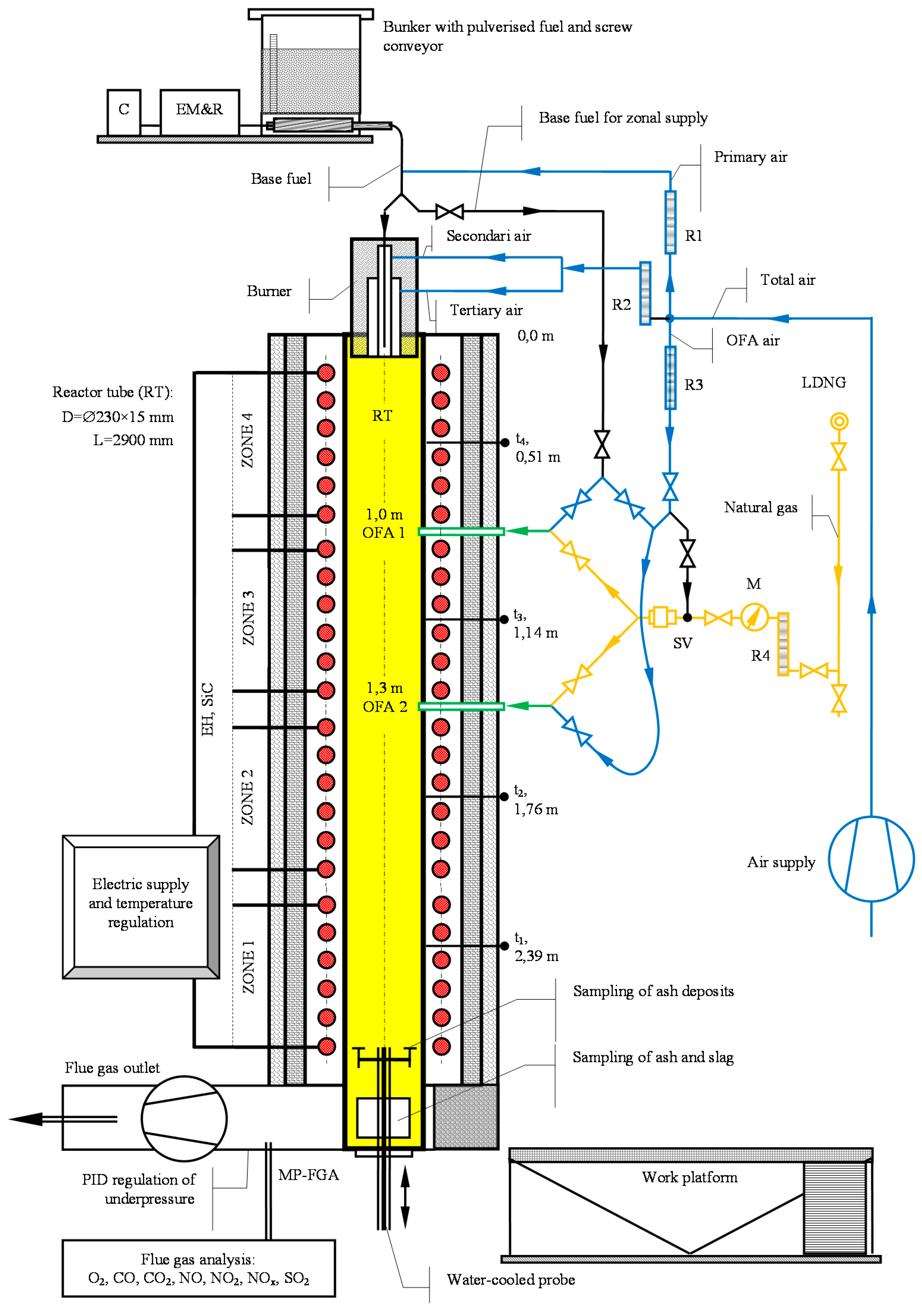
The lab-scale furnace is comprised of a 3 m length alumina-silicate ceramic tube, with a diameter of 230/200 mm, where combustion takes place, surrounded by SiC stick-type electric heaters and three-layer insulation, Figure 1. The temperature of the reaction zone is controlled by a programmable logic controller (PLC) with thyristor units for each of the four heating zones, allowing the process temperature to be varied at will across the range from ambient to 1560 °C.
The maximum power of the electrical heaters used to maintain temperature in the reaction tube is 70 kW, while nominal or thermal power of the furnace is 20 kW. Pulverized fuel is fed into the furnace by means of a volumetric feeder, mounted above the reactor. The feeder is equipped with a speed controller, allowing mass flow in the range of 0.25–5 kg/h. Air for combustion, coming from the air blower, is divided into carrier air (primary air), secondary air, tertiary air, and over fire air (OFA). The first three air portions are fed into the furnace over the swirl burner settled on the top of the reactor, so the air-fuel particle mixture flows downward, [12,14,15]. The excess air ratio was adjusted by tuning the air flow in each airline, at a constant fuel flow. The ceramic probes for collecting ash deposit were attached to a water-cooled lance probe, which could be moved along the reaction tube axis and set at the desired position, Figure 1.
2.5. Components Test Demonstration
Different kind of fuels were used; coal, woody biomass and energy crops miscanthus—processed to appropriate particle size by a laboratory hammer mill. Particle size distribusion of the fules is given in Table 2.
Test parameters to be used are basically as follows:
- TET 5 based fuels (1–3): t = 1250 °C, OFA, (PFC dry),
- TET 7 based fuels (4–6): t = 1250 °C, OFA, (PFC dry),
- TEK 6 based fuels (7–9): t = 1450 °C, OFA, (PFC slag tap),
- TEK 8 based fuels (10–12): t = 1250 °C, OFA, (PFC dry).
Excess air ration is corresponding to the real situation in boilers of power units in Tuzla and Kakanj TPP. Total excess air ratio is set at 1.15–1.2 at furnace outlet, while in first stage of combustion (on burner) is set to be at 0.95. Ratio of primary and secondary/tertiary air is adjusted on swirl burner for optimal air staging in primary zone i.e., optimal NOx and CO ratio. Thus, in all tests, optimized NOx and CO emissions were provided if primary (carrier) air portion was set at 1.50 mn3/h providing primary air ratio to be between 0.30 and 0.33. For air staging in the furnace, OFA varied from 0 to 0.30 of the overall amount of combustion air. Depending on fuel and excess air ratio used, total airflow rate was between 4.2 and 4.5 mn3/h, while flue gas flow rate was between 4.5 and 5.0 mn3/h.
Fuel thermal load is kept at same thermal input (approximately 5 kWth) in all the runs to provide comparison of the results. Depending on the fuel and excess air used, the total airflow rate is identified. The primary (carrier) air flow rate is set at 1.50 mn3/h for all the runs, with the rest of the air is divided into secondary and tertiary portions, approximately at a ratio of 2.5:1. So, primary/secondary/tertiary/OFA ratio is comparable with real situation in Tuzla TPP and Kakanj TPP. During the tests, ceramic probes are set 2 m away from the top of the burner (see Figure 1). After about 120 min of test running and ash collecting, the ceramic probes with ash deposits are carefully removed for further analysis of the deposits.
Emissions of NO, NO2, SO2 and CO are measured by a 350XL instrument (TESTO, Lenzkirch, Germany).
2.6. Experimental Uncertainties—Assessment of Applicability and Reliability of the Results
Experimental study relies on lab-scale tests in pulverized fuel (PF) furnace, performed according to good-laboratory practice procedure, as well as some of standard techniques like SEM, AFT, Oxide determination (Chemical composition analysis) etc. To better understanding the combustion mechanism while mixing the fuels, basic experiments have to be done using the TG, FTIR or GCMS, which is already planned by authors.
With regard to performed lab-scale tests, the results presented here are valid for cross flow around the tubes of the heat exchangers and for refractory combustion chamber walls, in terms of the real situation in large boiler. For vertical walls with parallel particle flow, the ceramic probes for ash collection should be set at an appropriate angle to the particle flow. Furthermore, it should be noted that, as a result of combustion, the coal particle temperature can be higher than that of the furnace wall, with potential implications for the ash transformation and deposition processes, [12]. Specific particle size distribution was used during the tests, as given in Table 2, as well as specific air distribution, as described in previous section. Finally, regarding the run time of 120 min, it should be stressed that it was the initial stage of slagging that was being examined during these tests.
Concering the type of testing procedure used, it should be noted that such lab-scale tests are not yet considered standard testing procedure, although many laboratories worldwide do use them, including TU Clausthal [10], IVD Stuttgart [16] and the University of Newcastle [17]. This type of testing procedure is accompanied by standard ancillary techniques for sample preparation, see e.g., [10], or standard chemical techniques that provide useful information, e.g., AFT or Oxide determination. These chemical techniques are, however, imperfect slagging or fouling predictors, and testing by experimental facility is advisable, as it provides a more reliable evaluation of the slagging/fouling propensity of the given fuels [17].
With regard to measurement of emissions, the measurement error is estimated for the NO emissions and SO2 emissions. Flue gas temperature is measured at the point in the partially insulated outlet tube where the gas sample is taken for emissions measurement. The processes in the flue gas line is frozen; there is no post combustion from the reactor to the TESTO 350XL instrument.
The aforementioned facts should be taken into account in considering the results presented here.
3. Results and Discussion
3.1. Combustion Efficiency
For biomass co-firing Tuzla coal blends TET5 and TET7 with woody biomass and Miscanthus, it can be noticed that the increase of the unburnt carbon content (UBC) in the ash deposits collected in Lab-scale furnace is only minor, from 0.0% to 0.04%. However, in the slag collected at the bottom of the furnace, the UBC is increased from 0.45% at 15% biomass co-firing, over 3.58% at 20% biomass co-firing to 6.92% at 25% biomass co-firing with TET7 coal. This implies that attention has to be paid to the combustion when co-firing above 15% of biomass with Tuzla coals at similar process conditions as used here, in order to keep combustion efficiency at an acceptable level.
For biomass co-firing with Kakanj coal TEK8, the increase of the unburnt carbon content (UBC) in the ash deposits collected in Lab-scale furnace is only minor, 0.0 to 0.02%. However, in the slag collected at the bottom of the furnace, the UBC is increased from 4.7% at 15% biomass co-firing, to over 8.48% at 25% biomass co-firing. This implies that attention has to be paid to the combustion when co-firing above 15% of biomass with coal at similar process conditions as used here, to keep combustion efficiency at an acceptable level.
3.2. Slagging
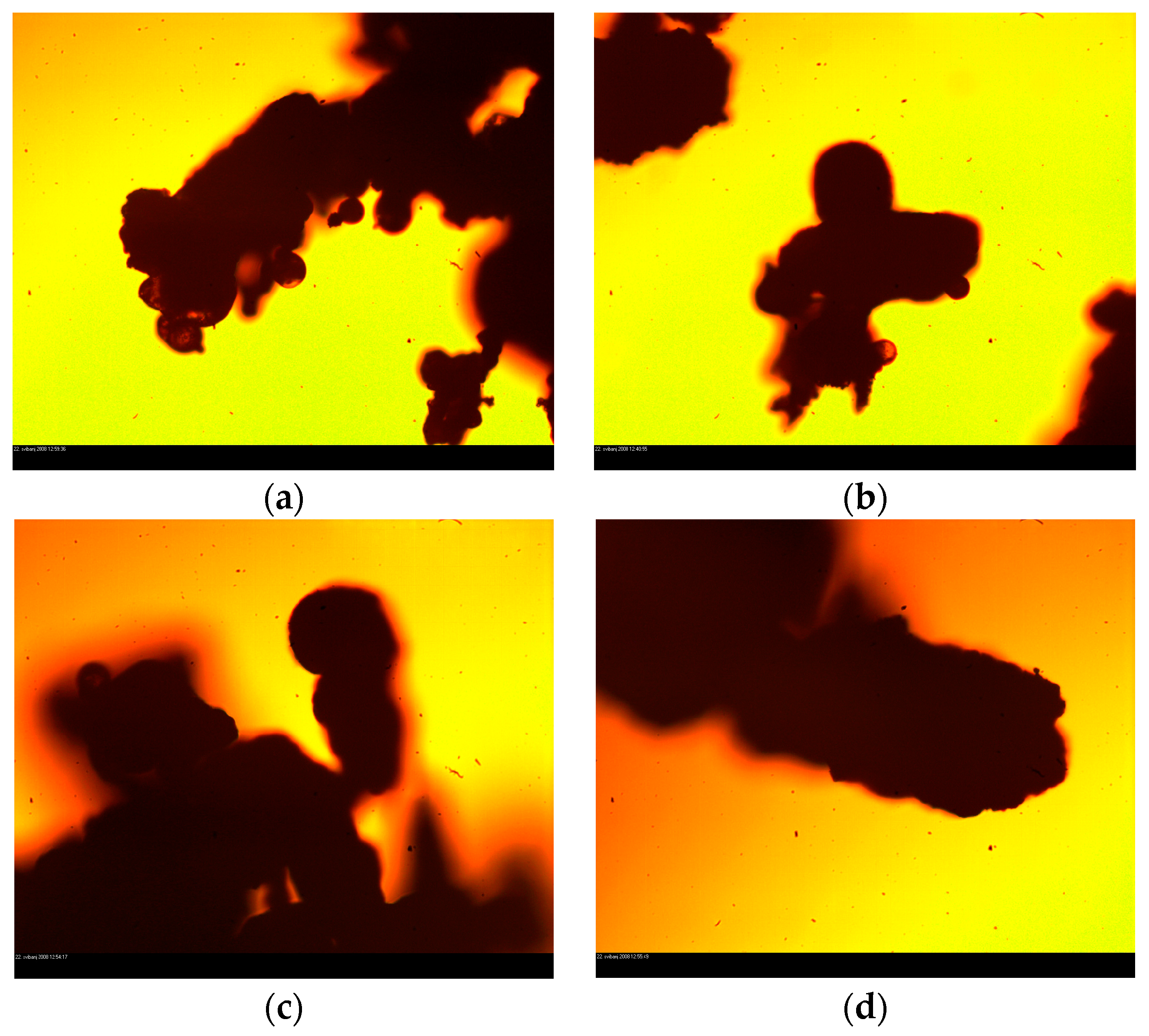
Evaluation of ash deposits is supported by visuals observation of the deposits (photographically and by microscope), as well as by chemical analysis of the deposits and deposition rate determination. So, multi-criteria assessment of slagging/deposition propensity has been applied, a method as reported in detail in [18]. Powdered, soft, hard and molten data points expressing different types of deposits can be identified, see for example in Figure 2 SEM images of ash deposits for different fuels. For coal alone ash deposits, see Figure 2a,b, one can notice melted ash spheres, indicating beginning of developed process of melting already at temperature of 1250 °C. It should be noted that melting is particularly expressed for ash deposit of mix of brown coal—Figure 2a, the coal which is more inclined to slagging than tested mix of lignite. This corresponded well with ash melting temperatures of the tested coal, see Table 2. From other side, one can notice that with adding woody biomass to mix of lignite, ash deposits becoming less melted, meaning the slagging propensity decreases, Figure 2c,d.
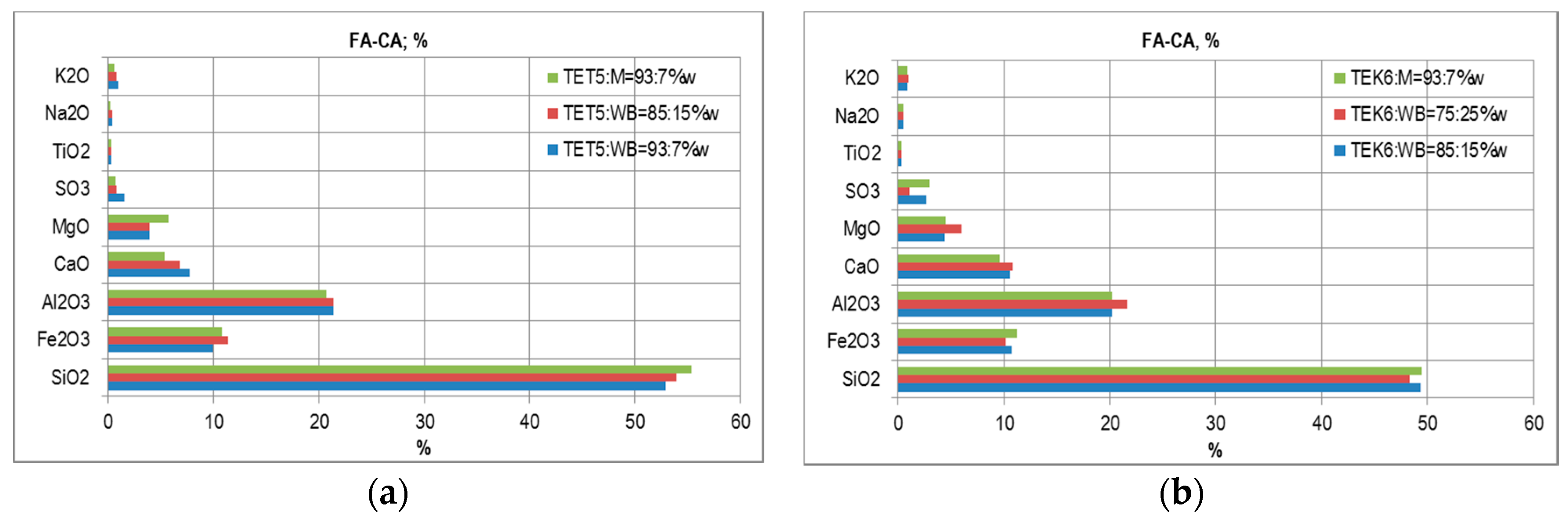
For all of the tested fuels, ash deposition rate can be determined as a mass of the deposit divided by the deposition area and time of deposition. Furthermore, oxide determination and Ash Fusion Test (AFT) of the deposits, fly ash or slag are also done to provide information on alkali metals distribution as a function of the type of fuel and the process temperature, as well as to investigate ash fusion behaviors. Oxide determination of fly ash for selected co-firing mixtures are given in Figure 3.
Based on the above presented multi-criteria assessment of ash deposits characteristics, final evaluation of slagging and fouling propensity for the given fuel and process conditions, is expressed in the following terms:
- Low slagging/fouling,
- Moderate slagging/fouling,
- Strong slagging/fouling,
- Very strong slagging/fouling.
Following aforementioned procedure, based on the presented results, evaluation of slagging for 12 co-firing regimes conducted is given in Table 3.
3.3. Emissions
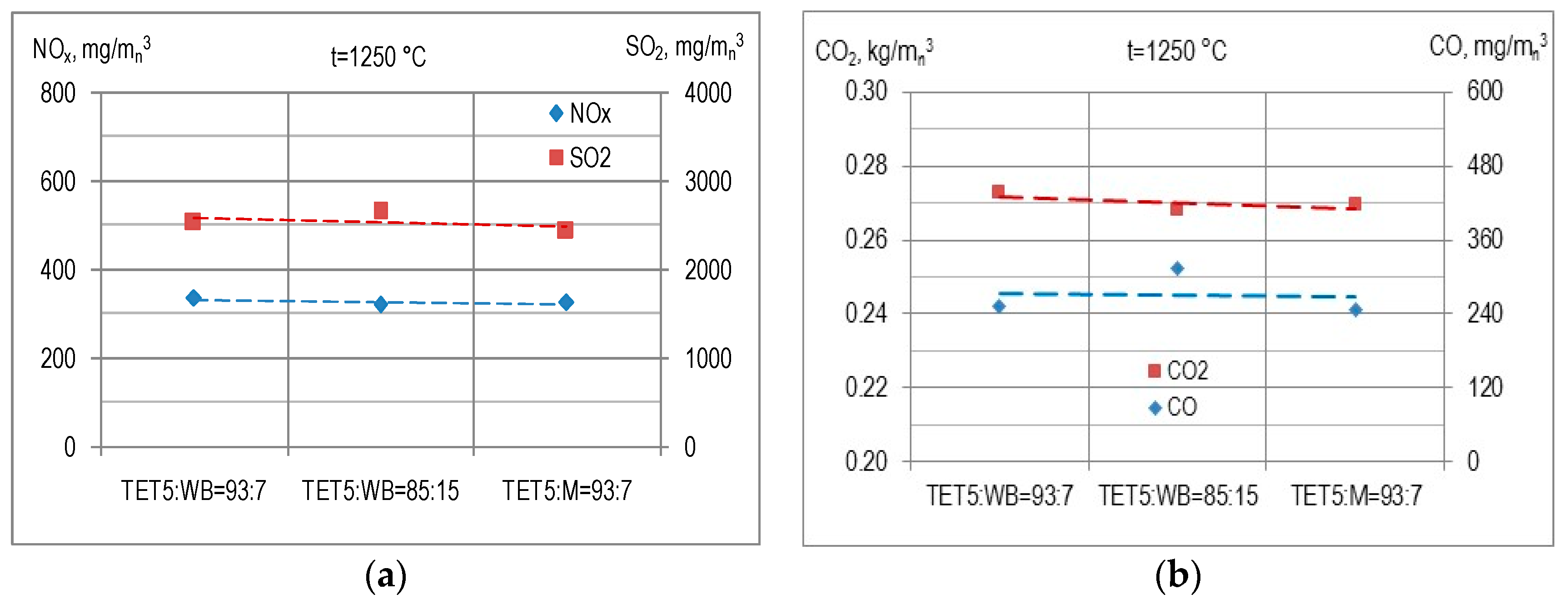
In Figure 4a, results of NOx and SO2 emissions during biomass co-firing with coal TET5 (lignite) are presented. Considering temperature of combustion of 1250 °C and sulphur content in the basic coal blend TET5 (S = 1.65%), SO2 emissions are at expected level of 2500 mg/mn3 at 6% O2 dry, which is comparable with SO2 emissions on Tuzla power plant Unit 5. It can be noticed a slightly higher emissions of SO2 when higher content of biomass is used, while Miscanthus slightly decreases SO2 emissions as compared to woody biomass.
Regarding NOx emissions, it can be noticed that those emissions are between 310 and 330 mg/mn3 at 6% O2 dry, with a quite slight variation between three fuels tested. At this, a bit lower NOx emissions have been recorded for biomass co-firing blend TET5:WB = 85:15 as compared to other two fuels. The same level of NOx emissions are on Tuzla power plant Unit 5 equipped with modern jet fuels in two rows and OFA system with ration between primary/secondary air against over fire air portion at 95:5—the same as used in these tests.
Higher CO emissions, as expected, have been recorded when co-firing coal TET5 with 15%wt of biomass as compared to 5% co-firing, see Figure 4b. This co-relates also with a bit lower NOx emissions in case of 15% co-firing, as shown in Figure 4a, which is phenomenon of NOx and CO correlation also reported by Wang [19], Li [20] and Rozendal [21]. During all co-firing test runs, lower NOx emissions were measured at the lower process temperatures, at the air staging and reburning, that is also reported in [20,21,22]. Despite of general decrease of NOx emissions recorded at higher biomass co-firing ratio, it was not, however, possible to identify clearly the correlation between the biomass content in the co-firing blend and NOx emissions during the tests.
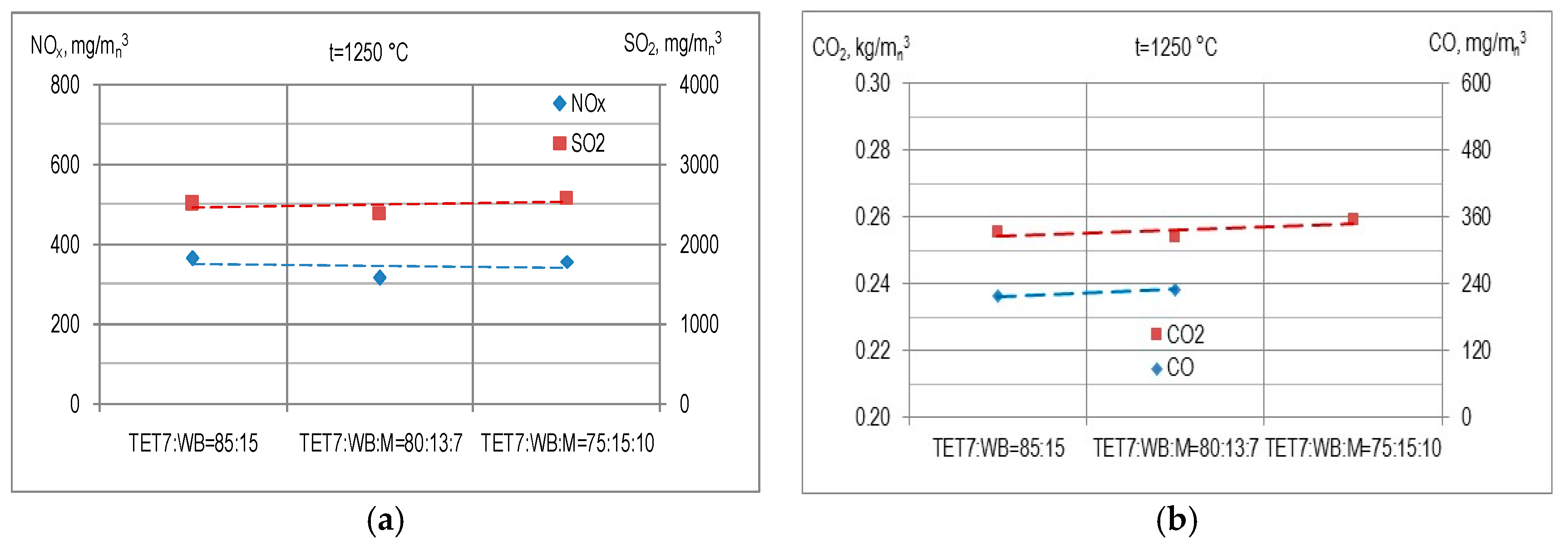
In Figure 5a, results of NOx and SO2 emissions during biomass co-firing with coal TET7 are presented. Considering temperature of combustion of 1250 °C and sulphur content in the basic coal blend TET7 (S = 1.57%), SO2 emissions are at expected level of 2500 mg/mn3 at 6% O2 dry, which is comparable with SO2 emissions for biomass co-firing with coal blend TET5. It can be noticed that slightly higher emissions of SO2 result when 25%wt of biomass is used as compared to 15% or 20% biomass co-firing. At this, it seems that miscanthus again slightly decreases SO2 emissions as compared when woody biomass is used.
Regarding NOx emissions, it can be noticed that emissions are now ranging between 310 and 375 mg/mn3 at 6% O2 dry, with a bit wider variation between three fuels tested as compared to biomass co-firing with coal blend TET5. This can be explained with higher percentages of biomass being used in this case. At this, a bit lower NOx emissions have been recorded for 20% biomass co-firing as compared to other two fuels.
Higher CO emissions, as expected, have been recorded when co-firing coal TET7 with 20%wt of biomass as compared to 15% co-firing, see Figure 5b. This co-relates also with a bit lower NOx emissions in case of 20% co-firing, see Figure 5a. A bit lower CO2 emissions are recorded, at level of 0.26 kg/mn3 as compared to case of TET5 based biomass co-firing (0.27 kg/mn3), see Figure 4b.
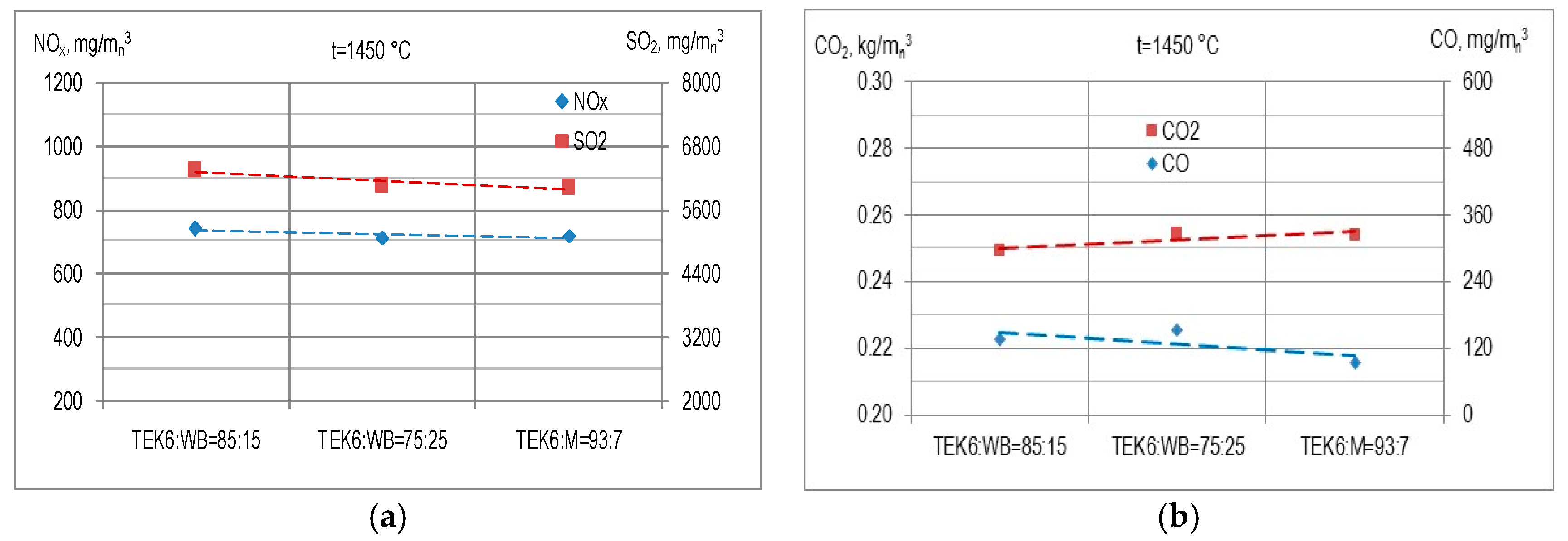
In Figure 6a, results of NOx and SO2 emissions during biomass co-firing with coal TEK6 are presented, at temperature of combustion of 1450 °C. Considering that high process temperature and consequently lower bounding of sulphur to the alkalis from the ash, as well as pretty high Sulphur content in the basic coal blend TEK6 (S = 2.46%), SO2 emissions are at expected level ranging from 6000 to 6400 mg/mn3 at 6% O2 dry. This is some lower emissions of SO2 as compared with SO2 emissions in regular operation of Kakanj Unit 6 where SO2 emissions are in the range of 7000–8000 mg/mn3 at 6% O2 dry. At this, 25% biomass co-firing reduces SO2 emissions as compared to 15% biomass co-firing, while it seems that Miscanthus again slightly decreases SO2 emissions as compared when woody biomass is used.
Regarding NOx emissions, it can be noticed that emissions are now in the range between 700 and 730 mg/mn3 at 6% O2 dry, which is slightly lower as compared to the NOx emission at Kakanj Unit 6 (750–850 mg/mn3 at 6% O2 dry) where the same swirl type burner as well 5% OFA ration is used as on Lab-scale furnace. This can suggest that biomass co-firing slightly decreased NOx emissions as compared to situation when coal alone is used.
Lower CO emissions (at 150 mg/mn3 at 6% O2 dry), as expected due to higher process temperature applied, have been recorded in this case as compared to biomass co-firing at lower temperature of 1250 °C. In the same time, lower CO emission is recorded when lower biomass percentage was used, see Figure 6b. This trend suits well to the trend of NOx emissions for the same fuel. A bit lower CO2 emissions are recorded (0.25 kg/mn3) as compared to TET5 and TET7 biomass co-firing, due to more convenient C/H ratio and higher calorific value of fuel in case of TEK6 biomass co-firing.
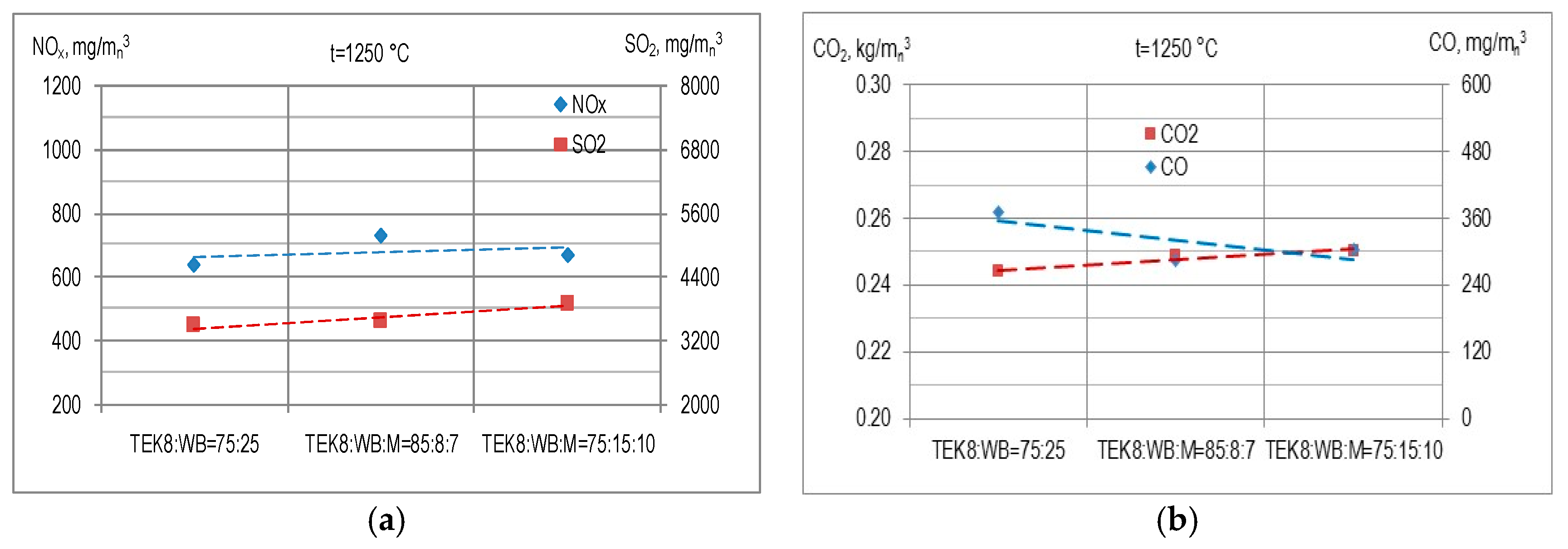
In Figure 7a, results of NOx and SO2 emissions during biomass co-firing with coal TEK8 are presented, at temperature of combustion of 1250 °C. Considering specifically high content of the Sulphur in this fuel (S = 2.47%) and a lower process temperature with consequently better bounding of Sulphur to the alkalis from the ash, SO2 emissions are at expected level ranging from 3500 to 4100 mg/mn3 at 6% O2 dry. This is much lower emissions of SO2 as compared with SO2 emissions in regular operation of Kakanj Unit 6 where SO2 emissions are in the range of 7000–8000 mg/mn3 at 6% O2 dry, at a process temperature of 1450 °C.
Regarding NOx emissions, it can be noticed that emissions are in the range between 630 and 710 mg/mn3 at 6% O2 dry, which is lower as compared to the NOx emission at Kakanj Unit 6 (750–850 mg/mn3 at 6% O2 dry) or in case of biomass co-firing with coal TEK8, due to lower process temperature used here. Additionally, it can be noticed that NOx emissions are lower for 25% biomass co-firing than in case 15% co-firing. This can suggest that an increase in biomass share produced slightly decreasing of NOx emissions in case of biomass co-firing with coal TEK8.
Double CO emissions, as expected due to lower process temperature applied, have been recorded in this case as compared to biomass co-firing for the similar coal and higher temperature of 1450 °C (case of biomass co-firing with TEK6). In the same time, lower CO emission is recorded when lower biomass percentage was used—case of 15% biomass co-firing, as compared to other two fuels with 25% biomass co-firing, see Figure 7b. This trend suits quite well to the trend of NOx emissions for the same fuel.
4. Conclusions
The given experimental results do show that there is reasonable expectation that tested coal/woody biomass/Miscanthus blends could be successfully co-fired in real operating conditions of PC Large Boiler, not producing any serious ash-related problem. Low or low-to-medium slagging propensity was noticed for all 12 co-firing case, at usual PC process temperature 1250 °C. The increase of the unburnt carbon content (UBC) in the ash deposits collected in Lab-scale furnace when increasing co-firing rate from 0.0 to 0.3 is only minor. However, in the slag collected at the bottom of the furnace, the UBC is increased for 0.15 and 0.2 biomass co-firing which implies that attention has to be paid to the combustion organization when co-firing above 15% of biomass at similar process conditions as used here, in order to keep combustion efficiency at an acceptable level.
In regard with emissions issue, it can be concluded that the results from performed biomass co-firing tests give some ground for optimism for achieving additional benefits, in particular for the co-firing with Miscanthus. While SO2 emissions have been at expected level, it can be noticed a slightly higher emissions of SO2 when higher content of biomass is used, while Miscanthus slightly decreases SO2 emissions as compared to woody biomass. That is in good correlation with the gas temperature recorded during the tests, which related to phenomenon of Sulphur capture rate, considering an identified increasing of gas temperature when higher woody biomass was used, while higher Miscanthus co-firing rate decreased the gas temperature. Regarding NOx emissions, both for biomass co-firing with lignite and brown coal, it can be noticed slight variations of NOx emissions between the tested fuels, with generally lower emissions when biomass co-firing rate was increased. Higher CO emissions, as expected, have been recorded in co-firing coal with higher share of biomass, as compared to lower biomass co-firing rate. This co-relates also with a bit lower NOx emissions in case of higher biomass co-firing rate.
The results suggest that woody sawdust and Miscanthus co-firing with Bosnian low rank coal types shows promising effects at higher ratios for pulverized combustion.
Acknowledgments
Authors aknowladge with thanks to EPBiH power utility and VPC GmbH for their kind cooperation and support.
Author Contributions
Nihad Hodzic and Anes Kazagic conceived and designed the experiments; Nihad Hodzic and Sadjit Metovic performed the experiments; Nihad Hodzic, Sadjit Metovic and Anes Kazagic analyzed the data; Nihad Hodzic and Sadjit Metovic contributed reagents/materials/analysis tools; Anes Kazagic wrote the paper.
Conflicts of Interest
The authors declare no conflict of interest.
References
- Kazagic, A.; Hodzic, N.; Metovic, S. Experimental Study on Co-Firing Low-Rank Coal and Woody Biomass with Harbacus Energy Crops Miscanthus in a Drop Tube Furnace. In Proceedings of the International Conference on Sustainable Development of Energy, Water and Environmental Systems—11th SDEWES, Dubrovnik, Croatia, 4–8 October 2017. [Google Scholar]
- KEMA. Technical status of biomass co-firing. In Proceedings of the IEA Bioenergy Task 32, Arnhem, The Netherlands, 11 August 2009. [Google Scholar]
- Lei, K.; Ye, B.; Cao, J.; Zhang, R.; Liu, D. Combustion Characteristics of Single Particles from Bituminous Coal and Pine Sawdust in O2/N2, O2/CO2, and O2/H2O Atmospheres. Energies 2017, 10, 1695. [Google Scholar] [CrossRef]
- Kakaras, E. Low emission co-combustion of different waste wood species and lignite derived products in industrial power plants. In Proceedings of the XXXII Krafwerkstechnisches Colloquium: Nutzung Schwieriger Brennstoffe in Kraftwerken, Dresden, Germany, 24–25 October 2000; pp. 37–46. [Google Scholar]
- Aziz, M.; Budianto, D.; Oda, T. Computational Fluid Dynamic Analysis of Co-Firing of Palm Kernel Shell and Coal. Energies 2016, 9, 137. [Google Scholar] [CrossRef]
- Wischnewski, R.; Werther, J.; Heidenhof, N. Synergy Effects of the Co-combustion of Biomass and Sewage Sludge with Coal in the CFB Combustor of Stadtwerke Duisburg AG. VGB PowerTech 2006, 86, 63–70. [Google Scholar]
- Chen, W.; Wang, F.; Kanhar, A.H. Sludge Acts as a Catalyst for Coal during the Co-Combustion Process Investigated by Thermogravimetric Analysis. Energies 2017, 10, 1993. [Google Scholar] [CrossRef]
- Mikulcic, H.; von Berg, E.; Vujanovic, M.; Duic, N. Numerical Study of Co-firing Pulverized Coal and Biomass inside a Cement Calciner. Waste Manag. Res. 2014, 32, 661–669. [Google Scholar] [CrossRef] [PubMed] [Green Version]
- Wang, G.; Silva, R.B.; Azevedo, J.L.T.; Martins-Dias, S.; Costa, M. Evaluation of the combustion behaviour and ash characteristics of biomass waste derived fuels, pine and coal in a drop tube furnace. Fuel 2014, 117, 809–824. [Google Scholar] [CrossRef]
- Kupka, T.; Mancini, M.; Irmer, M.; Weber, R. Investigation of ash deposit formation during co-firing of coal with sewage sludge, saw-dust and refuse derived fuel. Fuel 2008, 87, 2824–2837. [Google Scholar] [CrossRef]
- Williams, A.; Jones, J.M.; Ma, L.; Pourkashanian, M. Pollutants from the combustion of solid biomass fuels. Prog. Energy Combust. Sci. 2012, 38, 113–137. [Google Scholar] [CrossRef]
- Kazagic, A.; Smajevic, I. Synergy Effects of Co-firing of Woody Biomass with Bosnian Coal. Energy 2009, 34, 699–707. [Google Scholar] [CrossRef]
- Leckner, B. Co-Combustion: A Summary of Technology. Therm. Sci. 2007, 11, 5–40. [Google Scholar] [CrossRef]
- Hodzic, N.; Kazagic, A.; Smajevic, I. Influence of multiple air staging and reburning on NOx emissions during co-firing of low rank brown coal with woody biomass and natural gas. Appl. Energy 2016, 168, 38–47. [Google Scholar] [CrossRef]
- Kazagic, A.; Smajevic, I. Experimental investigation of ash behaviour and emissions during combustion of Bosnian coal and biomass. Energy 2007, 32, 2006–2016. [Google Scholar] [CrossRef]
- Maier, J.; Kluger, F.; Spliethoff, H.; Hein, K.R.G. Particle and emission behavior of raw and predried lignite in a 20 kW and in a 500 kW test facility. In Proceedings of the 23rd International Conference on Coal Utilization & Fuel Systems, Clearwater, FL, USA, 9–13 March 1998. [Google Scholar]
- Wall, T.F.; Juniper, L.; Lowe, A. State-of-the-Art Review of Ash Behaviour in Coal-Fired Furnaces; ACARP Project C9055; The University of Newcastle: Callaghan, Australia, 2001. [Google Scholar]
- Smajević, I.; Kazagić, A. Evaluation of Ash Deposits during Experimental Investigation of Co-firing of Bosnian Coal with Wooden Biomass. In Proceedings of the Tagungsband, Kunftiges Brennstoff- und Technologieportfolio in der Kraftwerkstechnik, 40. Kraftwerkstechnisches Kolloquium, Dresden, Germany, 14–15 October 2008; pp. 238–249. [Google Scholar]
- Wang, X.; Tan, H.; Niu, Y.; Pourkashanian, M.; Ma, L.; Chen, E.; Liu, Y.; Liu, Z. Experimental investigation on biomass co-firing in a 300 MW pulverized coal-fired utility furnace in China. Proc. Combust. Inst. 2011, 33, 2725–2733. [Google Scholar] [CrossRef]
- Li, S.; Xu, T.; Hui, S.; Wei, X. NOx emission and thermal efficiency of a 300 MWe utility boiler retrofitted by air staging. Appl. Energy 2009, 86, 1797–1803. [Google Scholar] [CrossRef]
- Rozendaal, M. Impact of Coal Quality on NOx Emissions from Power Plants. Ph.D. Thesis, Delft University of Technology, Delft, The Netherlands, 1999. [Google Scholar]
- Wang, Y.; Wang, X.; Hu, Z.; Li, Y.; Deng, S.; Niu, B.; Tan, H. NO Emissions and Combustion Efficiency during Biomass Co-firing and Air-staging. BioResources 2015, 10, 3987–3998. [Google Scholar]
Figure 1.
Principal scheme of the experimental furnace; C—speed controller of fuel supply, EM&R—electric motor and gearbox, RT—reaction tube, Ri—flow meters measuring the flow of air and natural gas, EH—SiC electric heaters arranged in four zones/levels, LDNG—laboratory distribution of natural gas, SV—safety valve with integrated flame arrester, M—manometer, MP-FGA—measuring point/flue gas analysis.

Figure 2.
SEM images of ash deposits during co-firing of lignite mixture TET7 with woody biomass; (a) coal TEK6, (b) coal TET5, (c) TET5:WB = 93:7%wt, (d) TET5:WB = 85:15%wt.
Figure 2.
SEM images of ash deposits during co-firing of lignite mixture TET7 with woody biomass; (a) coal TEK6, (b) coal TET5, (c) TET5:WB = 93:7%wt, (d) TET5:WB = 85:15%wt.

Figure 3.
Fly ash—chemical analysis (FA-CA) for selected co-firing regimes (a) biomass co-firing with lignite TET5, (b) biomass co-firing with brown coal TEK6.
Figure 3.
Fly ash—chemical analysis (FA-CA) for selected co-firing regimes (a) biomass co-firing with lignite TET5, (b) biomass co-firing with brown coal TEK6.

Figure 4.
Emissions for different biomass co-firing with coal TET5, (a) NOx and SO2 emissions (b) CO and CO2 emissions.
Figure 4.
Emissions for different biomass co-firing with coal TET5, (a) NOx and SO2 emissions (b) CO and CO2 emissions.

Figure 5.
Emissions for different biomass co-firing with coal TET7, (a) NOx and SO2 emissions (b) CO and CO2 emissions.
Figure 5.
Emissions for different biomass co-firing with coal TET7, (a) NOx and SO2 emissions (b) CO and CO2 emissions.

Figure 6.
Emissions for different biomass co-firing with coal TEK6, (a) NOx and SO2 emissions (b) CO and CO2 emissions.
Figure 6.
Emissions for different biomass co-firing with coal TEK6, (a) NOx and SO2 emissions (b) CO and CO2 emissions.

Figure 7.
Emissions for different biomass co-firing with coal TEK8, (a) NOx and SO2 emissions (b) CO and CO2 emissions.
Figure 7.
Emissions for different biomass co-firing with coal TEK8, (a) NOx and SO2 emissions (b) CO and CO2 emissions.


Table 1.
Fuel test matrix, temperatures and air ratio used, scope of chemical analyses performed.
| No. | Temperature, °C | 1250 | 1450 | |
|---|---|---|---|---|
| λ1/λ | 0.95/1.20 | 0.95/1.20 | ||
| Fuel Combinations | 1 | 2 | ||
| TET | 1. | TET5:WB = 93:7%wt | F-CA, A-CA, AFT D-UBC S-CA + AFT FA-CA + AFT | |
| 2. | TET5:WB = 85:15%wt | |||
| 3. | TET5:M = 93:7%wt | |||
| 4. | TET7:WB = 85:15%wt | F-CA, A-CA, AFT D-CA S-UBC | ||
| 5. | TET7:WB:M = 80:13:7%wt | |||
| 6. | TET7:WB:M = 75:15:10%wt | |||
| TEK | 7. | TEK6:WB = 85:15%wt | F-CA, A-CA, AFT D-UBC S-CA + AFT FA-CA + AFT | |
| 8. | TEK6:WB = 75:25%wt | |||
| 9. | TEK6:M = 93:7%wt | |||
| 10. | TEK8:WB = 75:25%wt | F-CA, A-CA, AFT D-CA S-UBC | ||
| 11. | TEK8:WB:M = 85:8:7%wt | |||
| 12. | TEK8:WB:M = 75:15:10%wt |
Table 2.
The basic characteristics of the mixed coals from TPP Tuzla, TPP Kakanj and different biomass.
Table 2.
The basic characteristics of the mixed coals from TPP Tuzla, TPP Kakanj and different biomass.
| Item | TET5 | TET7 | TEK6 | TEK8 | B100 | S100 | M100 |
|---|---|---|---|---|---|---|---|
| Mixed fuel | Šikulje:Dubrave:br. coal I | Dubrave:Šikulje | Kakanj:Breza:Zenica | beech | spruce | miscanthus | |
| (ratio by weight) | 40:35:25 | 50:50 | 100 | 70:20:10 | 100 | 100 | 100 |
| Proximate analysis, % | |||||||
| Moisture (wcrude) | 0 | 0 | 9.4 | 8.4 | - | - | - |
| Moisture (whygro) | 3.39 | 3.27 | 2.64 | 2.89 | - | - | - |
| Moisture (wtotal) | 3.39 | 3.27 | 12.04 | 11.29 | 39.57 | 44.07 | 12.33 |
| Ash | 41.67 | 38.28 | 36.98 | 41.38 | 0.53 | 0.24 | 4.28 |
| Combustible | 54.94 | 58.45 | 50.98 | 47.32 | 59.91 | 55.69 | 83.39 |
| Volatiles | 30.9 | 33.64 | 29.9 | 26.86 | 50.12 | 47.83 | 71.4 |
| Char | 65.71 | 63.09 | 58.06 | 61.84 | 10.31 | 8.1 | 16.28 |
| Fixed carbon (Cfix) | 23.9 | 24.79 | 20.94 | 20.38 | 9.79 | 7.86 | 11.99 |
| Sulfur (Stotal) | 1.65 | 1.057 | 2.46 | 2.47 | 0.07 | 0.11 | 0.15 |
| Sulfur (Sash) | 0.57 | 0.67 | 1.37 | 1.34 | 0.01 | 0.02 | 0.04 |
| Sulfur (Scombustible) | 1.08 | 0.9 | 1.1 | 1.14 | 0.06 | 0.1 | 0.11 |
| Ultimate analysis, % | |||||||
| Carbon (C) | 36.69 | 38.72 | 35.42 | 31.89 | 29.65 | 27.92 | 42.6 |
| Hydrogen (H) | 3.07 | 2.95 | 2.64 | 2.71 | 3.68 | 3.39 | 4.79 |
| Sulfur (Scombustible) | 1.08 | 0.9 | 1.1 | 1.14 | 0.06 | 0.1 | 0.11 |
| Nitrogen (N) | 0.79 | 0.86 | 0.62 | 0.64 | 0.11 | 0.11 | 0.11 |
| Oxygen (O) | 13.31 | 15.02 | 11.21 | 10.95 | 26.4 | 24.17 | 35.78 |
| Ash | 41.67 | 38.28 | 36.98 | 41.38 | 0.53 | 0.24 | 4.28 |
| Moisture (wtotal) | 3.39 | 3.27 | 12.04 | 11.29 | 39.57 | 44.07 | 12.33 |
| Heating values fuel, kJ/kg | |||||||
| HHV (Hh) | 14,688 | 14,870 | 14,018 | 12,989 | 11,215 | 10,476 | 15,361 |
| LHV (Hl) | 13,977 | 14,187 | 13,198 | 12,170 | 9546 | 8763 | 14,090 |
| Mineral analysis of ash, % | |||||||
| SiO2 | 54 | 59.01 | 43.2 | 46.12 | 6.62 | 7.15 | 67.76 |
| Fe2O3 | 9.98 | 8.38 | 9.18 | 9.58 | 1.2 | 0.9 | 4 |
| Al2O3 | 20.08 | 17.53 | 19.58 | 22.63 | 0.61 | 0.23 | 0.1 |
| CaO | 6 | 6.2 | 11.7 | 8.95 | 33.2 | 34.08 | 8.3 |
| MgO | 4 | 3 | 4.3 | 4.35 | 11 | 17.5 | 6.4 |
| SO3 | 3.44 | 4.36 | 9.26 | 6.05 | 2.57 | 2.99 | 6.34 |
| TiO2 | 0.4 | 0.4 | 0.35 | 0.35 | <0.10 | <0.10 | <0.10 |
| Na2O | 0.429 | 0.258 | 1.609 | 1.211 | 8.15 | 10.02 | 1.13 |
| K2O | 0.976 | 0.804 | 0.809 | 0.659 | 16.25 | 17.56 | 2.12 |
| Ash temperatures, °C | |||||||
| t2—softening. | 1300 | 1300 | 1240 | 1250 | 1300 | 1300 | 1150 |
| t3—hemisphere | 1350 | 1360 | 1310 | 1320 | 1400 | 1370 | 1250 |
| t4—flow | 1400 | 1400 | 1350 | 1360 | 1450 | 1420 | 1350 |
| Particle size distribution, % | |||||||
| >1.00 mm | 0 | 0 | 0 | 8.35 | 0.59 | 1.57 | 0.83 |
| >0.50 mm | 14.3 | 15.88 | 0.08 | 21.74 | 16.2 | 44.82 | 30.24 |
| >0.20 mm | 30.4 | 43.91 | 8.46 | 26.95 | 60.73 | 30.13 | 43.31 |
| >0.09 mm | 28.7 | 21.57 | 41.05 | 17.13 | 17.4 | 18.5 | 12.58 |
| <0.09 mm | 26.5 | 18.64 | 50.41 | 25.83 | 5.08 | 4.98 | 13.04 |
Table 3.
Evaluation of slagging.
| No. | Temperature, °C | 1250 | 1450 | |
|---|---|---|---|---|
| λ1/λ | 0.95/1.20 | 0.95/1.20 | ||
| Co-Firing Regime | Slagging Propensity | |||
| TET | 1 | TET5:WB = 93:7%wt | Low | |
| 2 | TET5:WB = 85:15%wt | Low | ||
| 3 | TET5:M = 93:7%wt | Low | ||
| 4 | TET7:WB = 85:15%wt | Low to Medium | ||
| 5 | TET7:WB:M = 80:13:7%wt | Low to Medium | ||
| 6 | TET7:WB:M = 75:15:10%wt | Low to Medium | ||
| TEK | 7 | TEK6:WB = 85:15%wt | Very Strong 1/Medium 2 | |
| 8 | TEK6:WB = 75:25%wt | Low to Medium | ||
| 9 | TEK6:M = 93:7%wt | Low | ||
| 10 | TEK8:WB = 75:25%wt | Low to Medium | ||
| 11 | TEK8:WB:M = 85:8:7%wt | Low to Medium | ||
| 12 | TEK8:WB:M = 75:15:10%wt | Low to Medium | ||
1 If considered to be used in Boiler with dry bottom furnace, 2 If considered to be used in Boiler with slag-tap furnace.
© 2018 by the authors. Licensee MDPI, Basel, Switzerland. This article is an open access article distributed under the terms and conditions of the Creative Commons Attribution (CC BY) license (http://creativecommons.org/licenses/by/4.0/).
Share and Cite
MDPI and ACS Style
Kazagic, A.; Hodzic, N.; Metovic, S. Co-Combustion of Low-Rank Coal with Woody Biomass and Miscanthus: An Experimental Study. Energies 2018, 11, 601. https://doi.org/10.3390/en11030601
AMA Style
Kazagic A, Hodzic N, Metovic S. Co-Combustion of Low-Rank Coal with Woody Biomass and Miscanthus: An Experimental Study. Energies. 2018; 11(3):601. https://doi.org/10.3390/en11030601
Chicago/Turabian StyleKazagic, Anes, Nihad Hodzic, and Sadjit Metovic. 2018. "Co-Combustion of Low-Rank Coal with Woody Biomass and Miscanthus: An Experimental Study" Energies 11, no. 3: 601. https://doi.org/10.3390/en11030601
Note that from the first issue of 2016, this journal uses article numbers instead of page numbers. See further details here.