Water Transport and Removal in PEMFC Gas Flow Channel with Various Water Droplet Locations and Channel Surface Wettability


Abstract
:1. Introduction
2. Model Formulation
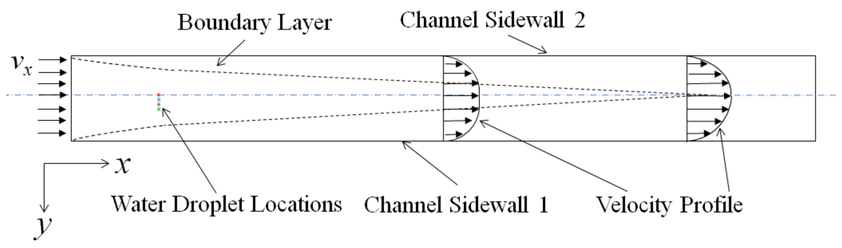
2.1. Computational Domain and Assumptions
2.2. Governing Equations and the VOF Method
2.3. Boundary and Initial Conditions
2.4. Numerical Technique and Grid
3. Results and Discussion
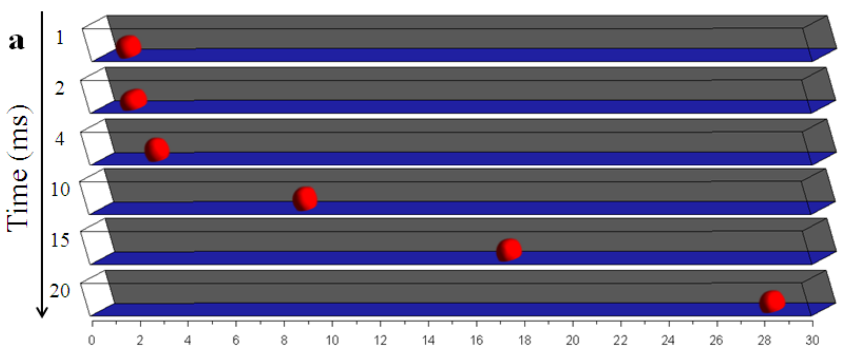
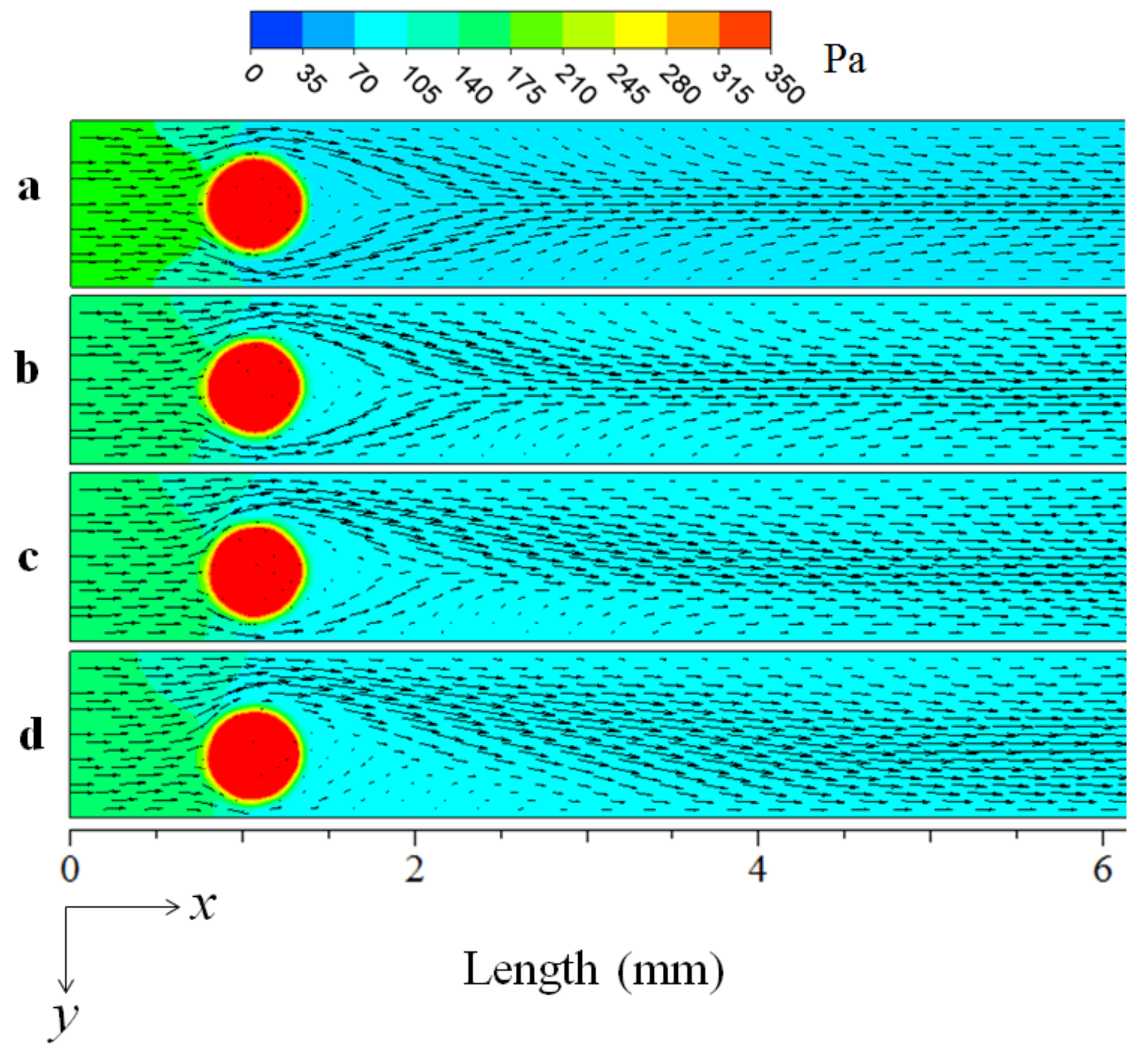
3.1. Effect of the Water Droplet Location
3.2. Effect of the Channel Surface Wettability
4. Conclusions
Acknowledgements
Author Contributions
Conflicts of Interest
Nomenclature
| A | water spreading area (m2) |
| D | water location (m) |
| Ddroplet | water droplet diameter (m) |
| f | volume fraction of the fluid |
| Fs | external force term (N·m−3) |
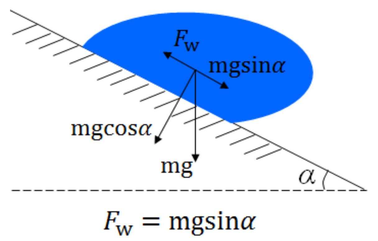
| Fw | wall adhesion force (N) |
| g, g | gravitational force (m·s−2) |
| k | constant in a correlation |
| n | surface normal |
| surface unit normal | |
| P | pressure term (Pa) |
| t | Time |
| v | velocity component (m·s−1) |
| V | volume (m3) |
| V | velocity vector (m·s−1) |
| Greek | |
| α | sliding angle (°) |
| θ | contact angle (°) |
| κ | surface curvature |
| µ | viscosity (kg·m−1·s−1) |
| ρ | density (kg·m−3) |
| σ | surface tension coefficient (N·m−1) |
| τ | wall shear stress component (Pa) |
| Subscripts | |
| 0 | Initial |
| 1, 2 | liquid water, air |
| a | advancing |
| channel | gas flow channel |
| droplet | water droplet |
| MEA | the membrane electrode assembly surface |
| Out | outlet |
| r | receding |
| S | source term |
| T | transpose |
| w | wall |
| x, y, z | axes |
References
- Jiao, K.; Li, X. Water transport in polymer electrolyte membrane fuel cells. Prog. Energy Combust. Sci. 2011, 37, 221–291. [Google Scholar] [CrossRef]
- Ji, M.; Wei, Z. A review of water management in polymer electrolyte membrane fuel cells. Energies 2009, 2, 1057–1106. [Google Scholar] [CrossRef]
- Bazylak, A. Liquid water visualization in PEM fuel cells: A review. Int. J. Hydrogen Energy 2009, 34, 3845–3857. [Google Scholar] [CrossRef]
- Le, A.D.; Zhou, B. Fundamental understanding of liquid water effects on the performance of a PEMFC with serpentine-parallel channels. Electrochim. Acta 2009, 54, 2137–2154. [Google Scholar] [CrossRef]
- Kim, B.; Lee, Y.; Woo, A.; Kim, Y. Effects of cathode channel size and operating conditions on the performance of air-blowing PEMFCs. Appl. Energy 2013, 111, 441–448. [Google Scholar] [CrossRef]
- Park, J.; Oh, H.; Lee, Y.I.; Min, K.; Lee, E.; Jyoung, J.Y. Effect of the pore size variation in the substrate of the gas diffusion layer on water management and fuel cell performance. Appl. Energy 2016, 171, 200–212. [Google Scholar] [CrossRef]
- Zhang, J.; Li, H.; Shi, Z.; Zhang, J. Effects of hardware design and operation conditions on PEM fuel cell water flooding. Int. J. Green Energy 2010, 7, 461–474. [Google Scholar] [CrossRef]
- Lee, C.Y.; Fan, W.Y.; Chang, C.P. Micro humidity sensor for monitoring water flooding in a proton exchange membrane fuel cell. Int. J. Green Energy 2012, 9, 389–397. [Google Scholar] [CrossRef]
- Park, Y.H.; Caton, J.A. Monitoring an electrode flooding through the back pressure in a proton exchange membrane (PEM) fuel cell. Int. J. Green Energy 2008, 5, 347–359. [Google Scholar] [CrossRef]
- Li, Y.; Pei, P.; Wu, Z.; Xu, H.; Chen, D.; Huang, S. Novel approach to determine cathode two-phase-flow pressure drop of proton exchange membrane fuel cell and its application on water management. Appl. Energy 2017, 190, 713–724. [Google Scholar] [CrossRef]
- Pei, P.; Li, Y.; Xu, H.; Wu, Z. A review on water fault diagnosis of PEMFC associated with the pressure drop. Appl. Energy 2016, 173, 366–385. [Google Scholar] [CrossRef]
- Zhang, F.Y.; Yang, X.G.; Wang, C.Y. Liquid water removal from a polymer electrolyte fuel cell. J. Electrochem. Soc. 2006, 153, A225–A232. [Google Scholar] [CrossRef]
- Chen, K.S.; Hickner, M.A.; Noble, D.R. Simplified models for predicting the onset of liquid water droplet instability at the gas diffusion layer/gas flow channel interface. Int. J. Energy Res. 2005, 29, 1113–1132. [Google Scholar] [CrossRef]
- Kumbur, E.C.; Sharp, K.V.; Mench, M.M. Liquid droplet behavior and instability in a polymer electrolyte fuel cell flow channel. J. Power Sources 2006, 161, 333–345. [Google Scholar] [CrossRef]
- Theodorakakos, A.; Ous, T.; Gavaises, M.; Nouri, J.M.; Nikolopoulos, N.; Yanagihara, H. Dynamics of water droplets detached from porous surfaces of relevance to PEM fuel cells. J. Colloid Interface Sci. 2006, 300, 673–687. [Google Scholar] [CrossRef] [PubMed]
- Xie, J.; Xu, J.; Shang, W.; Zhang, K. Mode selection between sliding and rolling for droplet on inclined surface: Effect of surface wettability. Int. J. Heat Mass Transf. 2018, 122, 45–58. [Google Scholar] [CrossRef]
- Quan, P.; Zhou, B.; Sobiesiak, A.; Liu, Z. Water behavior in serpentine microchannel for proton exchange membrane fuel cell cathode. J. Power Sources 2005, 152, 131–145. [Google Scholar] [CrossRef]
- Jiao, K.; Zhou, B.; Quan, P. Liquid water transport in parallel serpentine channels with manifolds on cathode side of a PEM fuel cell stack. J. Power Sources 2006, 154, 124–137. [Google Scholar] [CrossRef]
- Zhu, X.; Liao, Q.; Sun, P.C.; Djilali, N. Numerical investigation of water droplet dynamics in a low-temperature fuel cell microchannel: Effect of channel geometry. J. Power Sources 2010, 196, 801–812. [Google Scholar] [CrossRef]
- Park, J.W.; Jiao, K.; Li, X. Numerical investigations on liquid water removal from the porous gas diffusion layer by reactant flow. Appl. Energy 2010, 87, 2180–2186. [Google Scholar] [CrossRef]
- Yin, Y.; Wu, T.; He, P.; Du, Q.; Jiao, K. Numerical simulation of two-phase cross flow in microstructure of gas diffusion layer with variable contact angle. Int. J. Hydrogen Energy 2014, 39, 15772–15785. [Google Scholar] [CrossRef]
- Cai, Y.H.; Hu, J.; Ma, H.P.; Yi, B.L.; Zhang, H.M. Effects of hydrophilic/hydrophobic properties on the water behavior in the micro-channels of a proton exchange membrane fuel cell. J. Power Sources 2006, 161, 843–848. [Google Scholar] [CrossRef]
- Qin, Y.; Du, Q.; Yin, Y.; Jiao, K.; Li, X. Numerical investigation of water dynamics in a novel proton exchange membrane fuel cell flow channel. J. Power Sources 2013, 222, 150–160. [Google Scholar] [CrossRef]
- Qin, Y.; Li, X.; Du, Q.; Yin, Y.; Jiao, K. Effect of wettability on water removal from the gas diffusion layer surface in a novel proton exchange membrane fuel cell flow channel. Int. J. Hydrogen Energy 2013, 38, 12879–12885. [Google Scholar] [CrossRef]
- Qin, Y.; Li, X.; Jiao, K.; Du, Q.; Yin, Y. Effective removal and transport of water in a PEM fuel cell flow channel having a hydrophilic plate. Appl. Energy 2014, 113, 116–126. [Google Scholar] [CrossRef]
- Kim, H.Y.; Lee, H.J.; Kang, B.H. Sliding of liquid drops down an inclined solid surface. J. Colloid Interface Sci. 2002, 247, 372–380. [Google Scholar] [CrossRef] [PubMed]
- Jiao, K.; Li, X. Effect of surface dynamic wettability in proton exchange membrane fuel cells. Int. J. Hydrogen Energy 2010, 35, 9095–9103. [Google Scholar] [CrossRef]
- Chen, L.; He, Y.L.; Tao, W.Q. Effects of surface microstructures of gas diffusion layer on water droplet dynamic behaviors in a micro gas channel of proton exchange membrane fuel cells. Int. J. Heat Mass Transf. 2013, 60, 252–262. [Google Scholar] [CrossRef]
- Das, P.K.; Grippin, A.; Kwong, A.; Weber, A.Z. Liquid-water-droplet adhesion-force measurements on fresh and aged fuel-cell gas-diffusion layers. J. Electrochem. Soc. 2012, 159, B489–B497. [Google Scholar] [CrossRef]
- ANDYD. ANSYS FLUENT 12.1 User’s Guide; ANSYS Inc.: Canonsburg, PA, USA, 2009. [Google Scholar]
- Brackbill, J.U.; Kothe, D.B.; Zemach, C. A continuum method for modeling surface tension. J. Comp. Phys. 1992, 100, 335–354. [Google Scholar] [CrossRef]
- Shakhshir, S.A.; Wang, Y.; Alaefour, I.; Li, X. The influence of channel wettability on two-phase flow and polymer electrolyte membrane fuel cell performance. ECS Trans. 2012, 42, 109–115. [Google Scholar]
- Lv, C.; Yang, C.; Hao, P.; He, F.; Zheng, Q. Sliding of water droplets on microstructured hydrophobic surfaces. Langmuir 2010, 26, 8704–8708. [Google Scholar] [CrossRef] [PubMed]
- Miwa, M.; Nakajima, A.; Fujishima, A.; Hashimoto, K.; Watanabe, T. Effects of the surface roughness on sliding angles of water droplets on superhydrophobic surfaces. Langmuir 2000, 16, 5754–5760. [Google Scholar] [CrossRef]


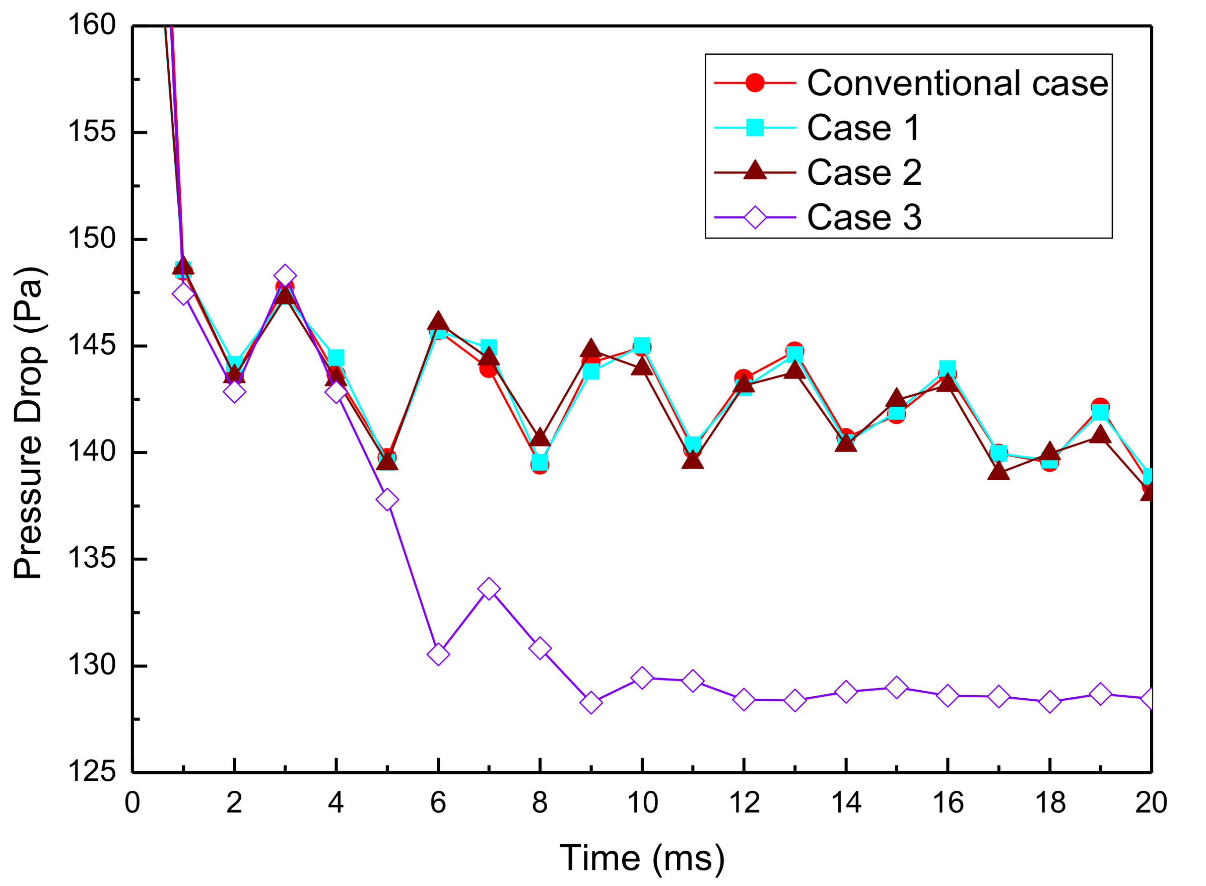
| Cases | D (mm) | θchannel (°) | αchannel (°) |
|---|---|---|---|
| Conventional case | 0 | 70 | 90 |
| Case 1 | 0.05 | 70 | 90 |
| Case 2 | 0.1 | 70 | 90 |
| Case 3 | 0.15 | 70 | 90 |
| Case 4 | 0.15 | 45 | 90 |
| Case 5 | 0.15 | 110 | 53 |
| Case 6 | 0.15 | 140 | 30 |
© 2018 by the authors. Licensee MDPI, Basel, Switzerland. This article is an open access article distributed under the terms and conditions of the Creative Commons Attribution (CC BY) license (http://creativecommons.org/licenses/by/4.0/).
Share and Cite
Qin, Y.; Wang, X.; Chen, R.; Shangguan, X. Water Transport and Removal in PEMFC Gas Flow Channel with Various Water Droplet Locations and Channel Surface Wettability. Energies 2018, 11, 880. https://doi.org/10.3390/en11040880
Qin Y, Wang X, Chen R, Shangguan X. Water Transport and Removal in PEMFC Gas Flow Channel with Various Water Droplet Locations and Channel Surface Wettability. Energies. 2018; 11(4):880. https://doi.org/10.3390/en11040880
Chicago/Turabian StyleQin, Yanzhou, Xuefeng Wang, Rouxian Chen, and Xiang Shangguan. 2018. "Water Transport and Removal in PEMFC Gas Flow Channel with Various Water Droplet Locations and Channel Surface Wettability" Energies 11, no. 4: 880. https://doi.org/10.3390/en11040880
APA StyleQin, Y., Wang, X., Chen, R., & Shangguan, X. (2018). Water Transport and Removal in PEMFC Gas Flow Channel with Various Water Droplet Locations and Channel Surface Wettability. Energies, 11(4), 880. https://doi.org/10.3390/en11040880