Passive Fuel Cell Heat Recovery Using Heat Pipes to Enhance Metal Hydride Canisters Hydrogen Discharge Rate: An Experimental Simulation

School of Engineering, RMIT University, Bundoora East Campus, Melbourne 3083, Australia
*
Author to whom correspondence should be addressed.
Energies 2018, 11(4), 915; https://doi.org/10.3390/en11040915
Submission received: 14 March 2018
/
Revised: 4 April 2018
/
Accepted: 9 April 2018
/
Published: 13 April 2018
(This article belongs to the Section D: Energy Storage and Application)
Abstract
:This paper reports on an experimental investigation of a passive thermal coupling arrangement between a Proton Exchange Membrane (PEM) fuel cell and a Metal Hydride (MH) hydrogen storage canister using heat pipes for enhancing the release rate of hydrogen. The performance of this arrangement was measured by inserting the evaporator sections of the heat pipes into an aluminum plate mimicking one out of five cooling plates of a 500-W fuel cell (that is a 100 W section of the stack). Thermal pads were attached on both sides of the plate to represent the fuel cell heat to be supplied to a 660-sl MH canister. The results showed that the operating temperature of the fuel cell can be maintained in the desired range of 60–80 °C. A complementary experimental study was also conducted on an 800-sl MH canister supplying hydrogen to a 130-W fuel cell stack (a slightly scaled-up setup compared to the first experiment). The study confirmed the findings of an earlier theoretical study by the authors that by supplying about 20% of the total cooling load of the stack to a MH canister, its maximum sustainable hydrogen supply rate increased by 70%, allowing for continuous operation of the stack at its rated power.
1. Introduction
A Proton Exchange Membrane Fuel Cell (PEMFC) can generate electricity by using the electrochemical reaction between hydrogen and oxygen (from air) supplied to the fuel cell, with heat and water as by-products [1,2]. The heat generated by the PEMFC has to be dissipated from the stack in order to maintain its temperature within a desired range (e.g., 60–80 °C) [3,4,5,6,7,8,9,10]. This heat can be captured and used for a range of Combined Heat and Power (CHP) applications such as hot water supply [11,12,13,14,15], space heating [16], pre-heating the PEMFC inlet air in cold climates [17,18], or thermal management of batteries in a hybrid battery fuel cell system (also in cold conditions) [19,20,21,22,23,24]. This heat can also be utilized to enhance the hydrogen release rate of Metal Hydride (MH) hydrogen storage canisters used to supply hydrogen to PEMFCs [25,26,27]. In MHs, hydrogen is stored in special metal alloys in atomic form [28]. Hydrogen molecules entering the storage canister can form weak bonds with metal particles at moderate pressures (e.g., ~10–40 barg) [29,30]. The hydrogen can be then released from the MH bonding by transferring the heat that can be absorbed from the ambient surrounding the MH canister or any additional heat supplied to the MH canister [30,31,32,33]. In general, proper thermal management is essential for MH canisters to increase their charge and discharge rates [34,35,36].
Due to relatively low release rates of hydrogen from MH canisters, usually it is a challenging task to match the hydrogen capacity in MH canisters with the hydrogen flow rate demanded by the PEMFC, particularly when the fuel cell operates at its rated power. Heating the MH canister enhances the release rate of hydrogen that suggests opportunities for recycling the heat generated by the fuel cell for this purpose [37,38].
The fuel cell stack demands a higher flow rate of hydrogen supply as its power output increases. On the other hand, the efficiency of a PEMFC drops as its power output increases up to its rated power. Hence the fuel cell cooling load (i.e., that needs to be removed from the stack) increases by increasing the fuel cell power output [39]. When using MH hydrogen storage, more heat is demanded by the hydrogen canisters to increase their supply rate (i.e., to meet the fuel cell demand at higher power outputs). The fact that the fuel cell generates more heat at higher power operating points correlates very well with increased demand of heat by the MH canisters (i.e., to release hydrogen at a faster rate) [40]. Hence the potentially-attractive opportunity arises of thermal coupling of a PEMFC with the MH canister used to supply it.
Several research studies have been reported in the literature that covered this possibility (e.g., [41,42,43,44,45,46,47,48,49]). However, these studies were mainly focused on using active methods (e.g., by using air or liquid) by employing heat exchangers or a water bath for heating and cooling of MH canisters and PEMFCs. Such active arrangements involve parasitic energy that decreases the overall energy efficiency of the fuel cell system. Heat pipes provide a solution for thermal coupling of PEMFCs and MH canisters that eliminate the parasitic energy associated with these active thermal management methods. Heat pipes can transfer high rate of heat in a passive way, and are currently used in many electronic applications such laptops [50,51,52], and batteries [53,54,55,56]. The use of heat pipes has been previously suggested for fuel cell cooling only [57,58,59,60]. The high thermal conductivity of heat pipes is their key advantage that can help remove a considerable amount of heat generated in a fuel cells quite effectively [61,62,63,64,65], while this heat can be transferred to MH canisters to enhance their hydrogen release rates. Moreover, they offer other advantages, such as simplicity and low maintenance, over conventional active cooling methods (e.g., water and air cooling) [66], while they can be assembled in different orientations and arrangements as required [67,68,69].
Apart from a theoretical study published by the authors previously [40], the use of heat pipes for thermal coupling of PEMFCs and MHs has not been thoroughly investigated before. Earlier studies on the thermal coupling of PEM fuel cells and MH canisters are reviewed in Section 2 of the present paper. This paper then focuses on an experimental investigation to study further the feasibility of this arrangement and confirm some of the results suggested earlier by a theoretical computer simulation [40] (Section 3 and Section 4).
2. Thermal Coupling of PEM Fuel Cell and MH Canister: A Literature Review
There are some published studies in which the heat generated by the PEMFC was recycled through active methods and used to heat up the MH canisters [70,71] (i.e., supplying hydrogen to the fuel cell). The electrical energy efficiency of PEMFCs is in usually in the range of 30–55% that means a substantial amount of heat is generated by the fuel cell stack as a by-product, while producing electricity. The cooling load of the stack is part of this total heat, since it excludes the heat used internally by the stack to evaporate the generated water and a small portion of heat taken out of the stack by the excess oxygen/air and hydrogen.
Some of the examples of active methods used for thermal coupling between the fuel cell and MH canisters are as follows: Wilson et al. [41] investigated the thermal coupling opportunities between a 1-kW PEMFC and two LaNi4.8Sn0.2-based MH canisters with the capacity of 280 sl (i.e., 25 g) of hydrogen each for 50 min of operation. A heating bath was used in the discharging mode that was set at 75 °C to help increase the hydrogen discharge rate from 4 slpm to 8 slpm at 2 bar of pressure, with heat being actively transferred from the stack to the heating bath. In a similar study Førde et al. [25] analyzed the thermal coupling of a 1.2-kW PEMFC (comprising of 22 cells with membrane active area of 170 cm2) and a 17.5-kg LaNi5-type MH canister (260 g) using a water circulation loop (U-tube) inside the canister. The heat generated in the PEMFC was used to enhance the hydrogen release rate in the MH canister at 30 °C. In this thermal coupling system, the MH canister was used to supply hydrogen to the fuel cell for three hours of operation at its rated power of 1.2 kW. In their experiment, the PEMFC’s cooling load was measured to be 800 W at the current density of 0.35 A/cm2 while on the other hand, the MH demanded for 200 W of heat (i.e., 25% of the total cooling load of the fuel cell) to enhance its discharging performance and match it with the fuel cell demand.
Pfeifer et al. [43] also published the result of their study on thermal coupling of a high temperature (i.e., operating at 160–200 °C) 1-kW PEMFC (with 10 cells and membrane area of 256 cm2) supported by four parallel MH hydrogen tanks filled with total of 2 kg sodium alanate, designed for storing 36 g of hydrogen enough for 2.5 h of operation. The heat from the PEMFC was transferred to the MH canisters using oil. The optimum condition in the MH was achieved by supplying 150 W of heat to the canister at the temperature of 185 °C; as the result, the hydrogen discharge rate was improved from 2 slpm to 3.5 slpm (75% improvement).
Urbanczyk et al. [72] analyzed the integration of a high-temperature 260-W PEMFCs (28 cells and effective cell area of 50 cm2) and a MH canister. In this arrangement, sodium alanate (2.7 kg) was used as the MH material with the capacity of storing 60 g of hydrogen (i.e., for three hours of operation). The MH canister was heated up by thermal oil flowing into a U-bend inside the canister transferring the heat generated by the PEMFC stack to the MH storage. By supplying 160 W of heat (i.e., from the fuel cell) to the MH canister at 120 °C the hydrogen discharge rate was reported to be improved from 195 lph to 255 lph (i.e., over 30% improvement).
In a more recent study published in 2014, Weiss-Ungethüm et al. [73] experimentally investigated the thermal coupling of a 400-W high temperature (HT) (160 °C) PEMFC (8 cells and 163.5 cm2) and a 300-g sodium alanate MH storage tank (2.6 wt. % of hydrogen) using direct liquid cooling (i.e., from the fuel cell point of view). A tube was used as a heating coil wrapped around the MH canister to provide additional heating and enhance the canister’s hydrogen discharge rate. By supplying 100 W of heat to the MH canister hydrogen discharge rate improved from 4.5 mg/s to 5.8 mg/s. Published in the same year (2014), Kim et al. [74] investigated the possibility of thermal coupling arrangement between a MH canister system and a 2.7-W PEMFC (8 cells with an active area of 1.68 cm2). The fuel cell was used as an alternative solution to a Li-ion battery system used for powering a mobile phone. The Mm-Ni-Mn-Co-based MH canister used in the study has a weight of 25 g (i.e., 1.5 wt. % of hydrogen). The results suggested that the thermal coupling arrangement between the PEMFC and MH canister, for mobile phone application, is a practical solution to operate the PEMFC at its peak power density of 200 mW/cm2, for six hours. The paper did not quantify the effect of this thermal coupling arrangement in terms of enhancing the MH hydrogen discharge rate.
By contrast, in the present paper, the opportunities for passive thermal coupling of these two components, by using heat pipes without any additional energy-consuming devices (i.e., to carry the fuel cell heat to the MH canisters), is experimentally investigated. While heat pipes are commonly used for cooling electronic equipment [51,52,75,76,77,78], only limited reported examples can be found in the literature (even at R&D stage) in which heat pipes have been used for either cooling of fuel cells [57,59,60,79,80], or heating up MH canisters [81,82,83]. The studies conducted on the use of heat pipes for fuel cell cooling, suggested the uniform temperature distribution across the stack and membrane and less weight and volume (i.e., at a system level) to be the key advantages of this approach [60,79]. These studies were mainly conducted for high temperature fuel cells (i.e., different ranges of around or above 100 °C) and they all suggested that the proper design of heat pipes can maintain the fuel cell temperature within its recommended range (i.e., ~60–80 °C) [57,59,60,80]. On the other hand, the studies conducted on the use of heat pipes for thermal management of MH canisters were mainly focused on reporting the significant effect of this thermal management method (i.e., using heat pipes) on charging and discharging capacities of the canisters as well as their charge and discharge rates (i.e., that improves charging and discharging times).
As mentioned before, the use of heat pipes for thermal management of fuel cells, or MH hydrogen storage canisters, have thus been studied as separate arrangements for each of these components in the past, but not as a combined system, to thermally couple the two components. An earlier theoretical study [40] tried to address this gap by developing a steady-state analytical model in MATLAB. The model was then applied on a 500-W PEMFC and five MH canisters (LaNi5, 660 sl) coupled using heat pipes. The cooling loads of the stack, at different operating points, were assumed to be available for use by the MH canisters. The model is though able to estimate how much of the fuel cell cooling load is required by the MH canisters (i.e., to match their discharge rate with the fuel cell demand). Considering a hydrogen utilization factor of around 85%, 7.2 slpm of hydrogen had to be supplied to the PEMFC at its maximum power operating point (i.e., 500 W). Five LaNi5-based MH canisters were used as hydrogen storage in this study (each 660 sl) with a total hydrogen discharge capacity of only 2.5 slpm (i.e., 0.5 slpm stable discharge rate for each canister) at ambient temperature conditions (i.e., 25 °C). Supplying the fuel cell heat to the MH canister was thus considered in order to match the hydrogen supply rate of the canisters with the hydrogen flow rate demanded by the fuel cell (i.e., 7.2 slpm at 500 W).
The results of this earlier analytical model (i.e., the details of the model provided in [40]) suggested that in order to match the hydrogen supply rate of the MH canisters with the flow of hydrogen demanded by the PEMFC (i.e., at its rated power of 500 W), 34 W of heat had to be transferred to each MH canister (LaNi5, 660 sl) to maintain their temperature at 35 °C (308 K) (i.e., both fuel cell and MH canisters were assumed to be thermally isolated). With this operating temperature (i.e., for the canisters) their hydrogen discharge rate limit could be lifted from 0.5 slpm to about 1.5 slpm such that with five canisters the maximum hydrogen flow demand by the fuel cell (i.e., 7.2 slpm) could be covered (i.e., with a safe margin). The heat demanded by the five canisters used in this study was calculated to be almost 20% (170 W) of the total cooling load (880 W) of the 500 W PEMFC (i.e., at maximum power operating point) used in the model. This finding closely agreed with an earlier result (i.e., with water cooling arrangement) obtained by Førde et al. [25] in which 25% of the total fuel cell cooling load was demanded by the canisters in order to match their hydrogen supply rate with the demand of the 1.2-kW fuel cell used in their study. In the model, the operating temperature of the stack was assumed to be 60 °C. Since only about 20% of the fuel cell cooling load was demanded by the MH canisters [40], the rest of the fuel cell cooling load would need to be rejected through another cooling arrangement (e.g., additional heat pipes and cooling plates). More investigation has been conducted experimentally to further understand the nature and detailed behavior of this thermal coupling. The details of this experimental study are described in the following section.
3. Experimental Investigation
3.1. An Overview
The present experimental study focused on studying the thermal coupling of fuel cells and metal hydride canisters using heat pipes by considering a similar arrangement to that employed in the earlier theoretical model [40]. To investigate how the heat pipes can thermally interact with the fuel-cell cooling plates, initially the thermal performance of 1/5th of the 500-W fuel cell, schematically shown in Figure 1, (i.e., equivalent to 100 W) was taken into consideration. One real cooling plate (i.e., that was used in the earlier theoretical study published by the authors [40]) was surrounded by a couple of thermal pads on both sides to mimic part of the 100-W fuel cell’s cooling load (to be transferred to the MH canister). Equivalent to the same amount of heat demanded by the MH canister (i.e., 20% of the total cooling load of the cells as suggested by the theoretical study) was generated by the thermal pads, which were connected to the cooling plates. The main objective of this experimental study was to provide ideas around the temperature range that the cooling plates can be maintained.
It is noteworthy that the PEMFCs are desired to operate at temperatures around 60–80 °C while the temperature distribution across the plate is preferred to be uniform. In fact, depending on real design constraints (e.g., space availability, and structural constraints), the MH canisters can be positioned on top of the fuel cell stack or underneath the stack. Obviously, the heat pipes show different levels of performance in each of these orientations (i.e., in terms of their heat removal capacity and their thermal resistance). If the stack is positioned on top of the MH canisters, then the heat pipes’ working liquid should travel back right against gravity from the condenser side toward the evaporator side: this is not a favorable condition for the heat pipes operation. On the other hand, when the heat pipes are placed on top of the stack, then the liquid travels from the condenser back to the evaporator with the support of gravity. Both orientations were taken into consideration in this experimental study.
A MH canister was also investigated experimentally to study its temperature distribution profile and hydrogen discharge rate while being heated up using the fuel cell heat transferred to them via heat pipes. This experiment was conducted by mimicking the heat generated by the PEMFC using a thermal pad (i.e., powered by a DC power supply) wrapped around the MH canister. The MH canister was also tested separately at ambient temperature (e.g., 20 °C) to analyze its hydrogen discharge rate (i.e., without the addition of heat from the fuel cell).
3.2. Heat Pipes to Transfer the Fuel Cell Heat from the Fuel Cell to the MH Canister
The key objective of this investigation was to look at the feasibility of using heat pipes as a passive device to remove the heat collected by a cooling plate in this representative part of the overall PEMFC stack. Specifically, the steady temperature of the cooling plate, the temperature distribution on the cooling plate and the heat removal capacity of the heat pipe system were investigated. The results were then compared with what the earlier theoretical calculations.
Considering the performance of the 100 W BSC PEMFC (i.e., with one cooling plates) that was used for this study (i.e., 1/5th of this 500 W stack) a basic setup with one cooling plate was manufactured. The heat that was supposed to be generated by seven cells around this cooling plate was generated using two DC thermal pads attached to both sides of the cooling plate. To minimize the heat losses, thermal insulation material (cotton wool) was used to cover the plate and the thermal pads. The 115 mm × 115 mm aluminum cooling plate, used in this study, was selected to be at the same size as the cooling and bipolar plates used in the original 500-W PEMFC stack. The thermal pads were also selected to be 80 mm × 80 mm to mimic the exact overall dimension of the membrane used in the 500 W PEMFC. The electrical power supply to the thermal pads where adjusted to generate the same level of heat demanded by the MH canisters. The generated heat in this experiment was adjusted to represent 20% of the total cooling load to be dissipated through one cooling plate of the stack (i.e., as suggested by the earlier theoretical study conducted by the authors [40]). The remaining 80% of the fuel cell cooling load is supposed to be removed by other means (e.g., extra heat pipes designed and sized for this purpose). These extra heat pipes whose evaporator sections were supposed to be inserted into the cooling plates are designed to take care of removing the remaining 80% of the cooling load to maintain the operating temperature of the fuel cell within the desirable range of 60–80 °C.
Seven heat pipes with the original diameter of 6 mm, flattened with the pressed thickness of 2 mm and the width of 8.50 mm at the evaporator section were inserted in the cooling plate. Each heat pipe had evaporator, condenser, adiabatic, and effective lengths of 80 mm, 100 mm, 100 mm, and 190 mm respectively. The evaporator sections of the heat pipes were inserted into the cooling plate and the condenser section of them were cooled using an adjustable flow of cold water (i.e., mimicking the heat demanded by a 660 sl MH canister designed to store 61 g of hydrogen). A circular water chamber (diameter of 150 mm and a length of 100 mm) was used to cool the condenser section of the heat pipes. To monitor the temperature distribution in the evaporator and the condenser sections of the heat pipes and the inlet and outlet of the water, several thermocouples were used, and a flow meter was used to monitor the flow of the cooling water throughout the chamber. The details of the experimental set-up and its schematic diagram are shown in Figure 1.
In this experiment, the heat in the range of ~20–55 W was supplied through the thermal pads and removed by the heat pipes (i.e., their evaporator side) inserted into the cooling plate. The heat pipes were then cooled (on their condenser side) using a flow of cold water passing through a water chamber. The flow of water was adjusted to achieve a steady temperature condition in the cooling plate (Figure 1). This heat removal arrangement was used for mimicking the heat demanded by the MH canister.
3.3. Fuel Cell Heat to Improve Metal Hydride Hydrogen Discharge Rate
3.3.1. Overview
In previous theoretical modeling conducted by the authors [40], five 660-sl LaNi5-based canisters were used to supply hydrogen to a 500 W stack (i.e., one canister per 100 W, as used in the present experimental study). In that study, heat pipes were used to transfer the fuel cell heat towards the MH canister and it was found that around 20% of the fuel cell heat is sufficient to maintain the hydrogen discharge rate of the canister at a suitable level required by the fuel cell. The purpose of this part of the experiment is to validate this finding. It is important to note that considering the availability of MH canisters in our laboratory, an 800 sl MmNiMnCo-based MH canister (i.e., with a higher hydrogen discharge capacity) was used for the experiment. Hence the stack to be supplied by this canister (i.e., for this part of the present experimental study) was proportionally assumed to be larger (i.e., about 130 W). To be able to validate the previous theoretical study, the theoretical modeling exercise was also repeated for this new 800 sl MH canister and a 130 W fuel cell case). The theoretical model on this scaled up case also confirmed that again about 20% of the fuel cell heat is enough to enhance the MH canister hydrogen supply rate such that it meets the fuel cell demand at its rated power (130 W).
3.3.2. Using Thermal Pads to Mimic the Fuel Cell Heat Transfer towards the MH Canister via Heat Pipes
In this experimental study the heat that is supposed to be transferred from the fuel cell to the MH canister via heat pipes was directly supplied to the canister using thermal pads. The MH canister (MmNiMnCo, 800 sl) was wrapped using a thermal pad for supplying heat to that during discharging (i.e., equivalent to 20% of the fuel cell cooling load to be removed at 130 W operating point). A thermal insulation layer (i.e., cotton wool) was used to minimize the error caused by the heat losses from the MH canister surface. The heat supplied by the DC-powered thermal pads was adjusted to represent the theoretically-calculated heat demanded by the MH canisters (i.e., to match their supply rate with that demanded by the fuel cell at 130-W operating point). This heat input was selected to be 45 W and the heat pipes were supposed to carry this heat from the fuel cell stack to the canister. According to the theoretical model, by transferring this heat to the 800 sl MH canister its hydrogen release rate could increase from 1 slpm to 1.7 slpm (i.e., enough to supply the fuel cell demand for hydrogen at 130 W). The schematic diagram and the actual set-up of the experiments for hydrogen discharge are shown in Figure 2a,b.
We assumed that the heat pipes are well insulated; however, imperfect operation of the heat pipes (in a real practice of this arrangement) is not expected to change the outcome of this experiment for two reasons: (i) the MH canister demands only ~20% of the total fuel cell cooling load. This means if any heat is lost through the body of the heat pipe (e.g., from the adiabatic section of the heat pipe), more fuel cell heat is available to compensate any shortfall of heat causes by such thermal leaks; (ii) the heat transfer capacity of heat pipes have been selected to be slightly above what is needed to be transferred, so that such thermal leaks would not affect the capacity of heat pipes in transferring 20% of the fuel cell heat towards the MH canister. With these two key assumptions, we can make sure that using thermal pads supplying the same amount of heat that is supposed to be transferred by the heat pipes is an accurate way of mimicking the thermal bridging role of the heat pipes.
It is important to underline the point that the present thermal coupling arrangement is studied at the system’s critical condition with fuel cell operating at its rated power (i.e., 100 W) at which its demand rate for hydrogen is maximum (i.e., that may not be reached by the MH canister’s supply rate). We assume, as in a healthy fuel cell, the cooling system of the fuel cell is designed to maintain its temperature at around 60 °C in all operating points. Considering the 20% fuel cell cooling load directed to the MH (i.e., from the fuel cell), the demand for heat (from the fuel cell) is reduced at lower power operating points as less flow of hydrogen is required by the fuel cell. That gives the system the chance of self-regulating itself and maintaining its temperature at the level desired by the fuel cell (i.e., ~60 °C). Sometimes at low power outputs the temperature of the fuel cell goes up very slowly or does not go up at all (i.e., when the stack’s surrounding temperature is quite low). However, operation in extreme cold climate conditions remained outside the scope of this work.
4. Results and Discussion
4.1. Heat Pipes to Transfer Heat from the Simulated Fuel Cell
The temperature variations with respect to time at different points (shown in Figure 1) were recorded until they reached steady conditions (i.e., with adjusted water flow rates). These variations are shown in Figure 3 and Figure 4. For example the results demonstrated in Figure 3 and Figure 4 were specifically obtained with supplying 39 W of heat to the cooling plate through the thermal pad, slightly higher than 34 W of heat removal, suggested by the earlier theoretical study (i.e., to take into account a small percentage of heat that can be lost through the insulation layer around the system).
According to these results the temperature of the evaporator section of the heat pipes (i.e., where connected to the cooling plates) initially increased sharply and then saturated by reaching a steady condition. The middle sections of the heat pipes were well insulated so that almost the same amount of heat collection was measured (i.e., through the cold water flow) on the condenser side. For gravity orientation heat pipes (i.e., where the evaporator is on the bottom side of the heat pipes), in which the gravity effect supports the liquid to move back to the evaporator section, this steady temperature was recorded to be between ~50 °C (i.e., on the side of the membrane active area) and 60 °C (i.e., in the center of the membrane active area). The steady conditions were achieved in about 17 min (i.e., ~1000 s). By changing the orientation of the heat pipes for the working liquid to be moving against gravity (i.e., with the evaporator positioned to be on the top side of the heat pipes), the steady temperature of the points monitored in this experiment were recorded to be settled at about 5 °C higher than the previous case (i.e., bottom heat pipes), that is 55–65 °C. In this case, it took longer to achieve steady condition (i.e., about 35 min) and the temperature of the condenser side was recorded to be slightly lower than when the heat pipes were used in gravity orientation (i.e., due to a poorer heat transfer capacity of the heat pipes).
As a comparison, the temperature variations with respect to time at different points on the heat pipes using higher heat input (e.g., 55 W) are shown in Figure 5 and Figure 6. Similar to the previous results provided in Figure 3 and Figure 4, the temperature of the evaporator section of the heat pipes (i.e., where connected to the cooling plates) initially increased sharply and then saturated by reaching a steady condition. For heat pipes with gravity orientation, the steady temperature was recorded to be between ~60 °C (i.e., on the side of the membrane active area) and 80 °C (i.e., in the center of the membrane active area). On the other hand, for heat pipes with against gravity orientation, the steady temperature was recorded to be in the range of 75–90 °C. This is just to show the heat removal capacity of the system at higher temperature; however, in practice the heat that is supposed to be transferred from the cooling plate to the MH canister was not expected to exceed ~34 W (according to previous validated theoretical investigated conducted by the authors) [40].
The steady temperature of the heat pipes on their evaporator section (i.e., two different orientations: gravity and against gravity) as a function of the heat generated by the 100-W stack (that is 1/5th of the 500 W fuel cell stack used for the earlier theoretical study) is presented in Figure 7. The heat was generated by the thermal pads (i.e., mimicking the heat that is supposed to be generated by the stack) and was adjusted to represent the heat demanded by the MH canister to match its hydrogen release rate with the fuel cell demand for hydrogen. The graphs show that by increasing the heat supplied by the thermal pads, the temperature of the evaporator section of the heat pipe increases (i.e., in both orientations). By supplying 39 W of heat (i.e., demanded by the MH canisters to supply the fuel cell at 100 W operating point) the temperature of the cooling plate and the evaporator section of the heat pipes can reach the maximum steady level of 60 °C and 65 °C, for gravity and against gravity orientations respectively. It is worth noting that the 39 W of heat applied was equivalent to just over 20% of the total cooling load of the 100-W stack, demanded by the MH canister. As shown in Figure 7, by using the heat pipes against the gravity, their performance (i.e., their thermal conductivity) become more sensitive to the level of heat input (i.e., compared to gravity ordination). This is mainly due to higher pressure drops in heat pipes when used against gravity.
Based on previous theoretical study conducted by the author on a 500-W PEMFC and five 660-sl LaNi5-based MH canisters [40], almost 170 W of heat was needed to match the supply rate of the canisters (each connected to one out of five cooling plates in this stack) with the fuel cell demand at its rated power (i.e., 500 W). Looking at 34 W (1/5th of 170 W) operating point on the graph (Figure 7), the steady temperature of the cooling plate and the evaporator section of the heat pipe can reach the maximum of about 55 °C, that is a perfectly-acceptable operating temperature level for a PEMFC. Even by slightly increasing the level of this heat (i.e., if a different MH is used), such as 39 W that was used in this experiment, the steady temperature of the plate does not cross a maximum in the range of 60–65 °C (that is still an acceptable temperature to operate the fuel cell at). It is important to note that still more heat pipes arrangements are required to be installed because the MH canister only demands 20% of the total cooling load of the PEMFC, and the remaining 80% should be removed through these additional heat pipes. It is also noteworthy that although the experiment was conducted for the heat inputs as high as 55 W for this case study, in practice (i.e., based on previous theoretical calculations [40]) the heat input for a similar case is expected to be in the range of 30–40 W (i.e., for one cooling plate connected to one MH canister). Hence, high temperatures as high as 90 °C (i.e., corresponding to 55 W of heat input as indicated by Figure 7) is well away from the operating region of this case. In a similar way by up-scaling or down-scaling the case, considering the heat demanded by the MH canisters, this thermal arrangement is expected to maintain the stack’s operating temperature at about 60 °C.
By measuring the temperature difference across the condenser and evaporator sides of the heat pipes, their thermal conductivity and resistances were also calculated. The results showed that, as also mentioned in other studies [61,75], these parameters have close links to the level of heat to be carried by the heat pipes. The thermal conductivity and the thermal resistance of the heat pipes as a function of heat supplied by the thermal pads (i.e., to be carried away by the heat pipes) for two different orientations for the heat pipes (gravity and against gravity orientations) are presented in Figure 8. In the gravity orientation, the thermal resistance remained to be almost stable at 6 °C/W for heat supply rates within the range of 20 W–55 W for each cooling plates (that is ~3–7 W per heat pipe, with 7 heat pipes connected to each cooling plate) and accordingly the thermal resistance was almost constant. However, for the total supply rates above 50 W for each cooling plate (i.e., just over 7 W per heat pipe), by increasing the heat supplied by the thermal pads (i.e., the fuel cell), the thermal conductivity of the heat pipes decreased and accordingly their thermal resistance increased. This observation agrees with what presented earlier by Do et al. [84] and Putra et al. [85] where screen mesh wicks were used in the heat pipes. By putting the heat pipes in against the gravity orientation, the thermal resistance increased sharply from 6 °C/W to 8.6 °C/W by applying the same range of heat inputs (i.e., 20 W–55 W) as that used for gravity orientation).
In the present case, the heat pipes used for removing heat from the fuel cell are showing relatively high effective thermal conductivities (i.e., up to just over 1000 W/m·°C), which would help make the temperature distribution across the plate more uniform. It is important to note that in the presented case study the heat removal load of the seven heat pipes (connected to each cooling plate) is expected to be mainly between 30 W and 40 W, where the heat pipes are showing their relatively higher performance in terms of thermal conductivity and resistance (i.e., Figure 8). Within this range of heat inputs, the heat pipes used in this study are showing around 1060 W/m·°C and about 730–1030 W/m·°C of thermal conductivity for gravity and against the gravity orientations, respectively. These values are in a good agreement with those suggested earlier by Franchi and Huang [86], Solomon et al. [87] and Asirvatham et al. [88], where screen mesh wicks were used.
4.2. The Effect of MH Canister Heating on Its Hydrogen Release Rate
The hydrogen release rate was first tested at ambient temperature (i.e., 20 °C) with no external supply of heat to the MH canister (i.e., heat could only be absorbed by the canister from the ambient). By extracting hydrogen from the MH canister, its temperature started to drop that led to decreasing the hydrogen release rate as shown in Figure 9. Within 15 min, the maximum flow rate of hydrogen dropped from just over 5 slpm down to 2 slpm (with 1% measurement error); while the MH outer surface temperature decreased from 20 °C, down to about 7 °C (with 1% measurement error). 2 slpm was still fine to meet the demand of the 130-W stack at its rated power (that requires about 1.7 slpm). However, by moving on by another couple of minutes the canisters hydrogen release rate become insufficient to meet the demand rate of the stack. By keeping the canister to be discharged at its full capacity (i.e., at any time) it took about another 15 min for the MH temperature to drop down to about 3 °C with a maximum hydrogen release rate of just below 1 slpm (i.e., well below the 130 W stack’s hydrogen flow requirement). This is a very similar behavior suggested earlier through the theoretical study conducted by the authors [40] (Figure 10).
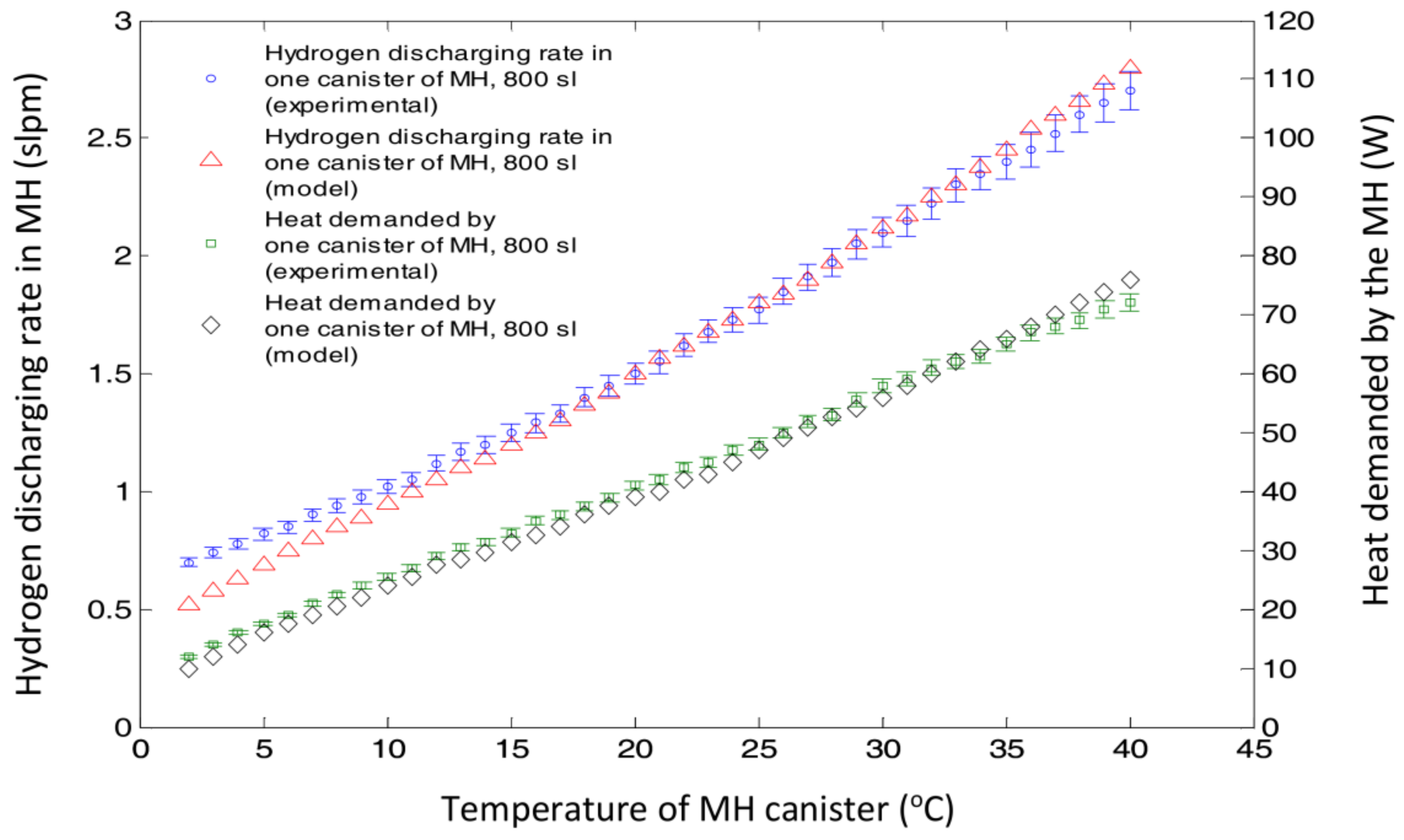
The second step was repeating the discharging process in the presence of the heat, to be presumably supplied by the fuel cell stack (i.e., here in this experimental case the heat was supplied through DC thermal pads, mimicking the fuel cell heat). This new 800 sl MH canister was also modelled theoretically (the details of the model can be found in [40]), and the theoretical and the experimental results were compared in Figure 10, that in fact show a close matching between them. The heat requirement of the canister was suggested to be 45 W to supply enough hydrogen to the fuel cell at 130 W operating points. Hence, the MH canister hydrogen discharge rate and temperature were monitored by supplying heat in the range of 40 W–75 W (i.e., to cover a reasonable range around the 45 W suggested by the theoretical calculations). Both theoretical and experimental studies suggested that the canister can maintain around 1.7 slpm of hydrogen supply rate (i.e., demanded by 130 W stack at its rated power) by absorbing 45 W of heat, while its temperature is maintained at about 25–30 °C (when thermally insulated). The results also showed that the hydrogen supply rate and MH surface temperature both linearly related to the heat supplied to the MH through its outer surface.
5. Conclusions
The thermal coupling of a PEMFC and a MH canister using heat pipes was investigated experimentally and, where applicable, the results were compared with the output of the earlier theoretical model published in [40]. The heat pipes were used as a passive solution to transfer the fuel cell heat to the MH canisters to enhance their hydrogen release rates. The experimental study was conducted by using actual cooling plates covered by DC thermal pads to generate 20% of the total fuel cell cooling load that is demanded by the MH canister (as suggested by earlier theoretical study). This heat (i.e., 20% of the total fuel cell cooling load) is the heat demanded by the MH canisters to maximize their hydrogen release rate and match the fuel cell demand for hydrogen. It was assumed that the rest of the fuel cell cooling load is removed through other arrangements (e.g., by installing additional heat pipes on the cooling plates). The experimental investigation on a representative part of the stack showed that by using heat pipes for thermal management of the PEMFC, it should be possible to maintain the operating temperature of the whole fuel cell stack in the desirable range of 60 °C to 80 °C. The effect of supplying heat to the MHs was also studied separately. Equivalent to 20% of the total fuel cell’s cooling load (i.e., 45 W for a ~130 W stack) that was supposed to be transferred from the stack to the MH canister (i.e., using heat pipes), was supplied to the canister using DC thermal pads. An 800-sl MmNiMnCo-based MH canister was used for this study. Before supplying heat, the discharge rate of the canister at 20 °C started to drop from an initial value of about 5 slpm down to below 1 slpm in 30 min while the temperature of the canister approached 3 °C (from an initial value of over 20 °C). However, by transferring 20% of the fuel cell heat to the canister (i.e., 45 W in this case), using heat pipes, it was possible to maintain the canister’s temperature at about 25–30 °C with a sustained supply capacity of 1.7 slpm (i.e., enough to meet the hydrogen flow demanded by the 130 W stack at its rated power).
Acknowledgments
The authors of this article would like to thank the Indonesia Endowment Fund for Education (LPDP) for a PhD scholarship to Anggito P. Tetuko, and RMIT University’s Capability Technology Demonstrator Project on “The development and demonstration of a low signature, rechargeable and portable energy supply using reversible hydrogen fuel cells to support forward operating bases” funded by the Australian Defence Science and Technology Group, for supporting part of this research.
Author Contributions
Bahman Shabani contributed to this work by his inputs for developing the idea, designing the experiments, and providing directions on developing a theoretical simulation study (published earlier and validated by these experiments) as well as supervising the project. Anggito P. Tetuko contributed to developing the idea, conducted the experiments, developed the earlier mathematical models (that the experimental results are compared with) and analyzed the data. John Andrews contributed to this work with his inputs for designing the experiments, reviewing the results as well as supervision role. Finally, all authors contributed to drafting and polishing this paper with a major share done by Anggito P. Tetuko.
Conflicts of Interest
The authors declare no conflict of interest.
References
- Larminie, J.; Dicks, A. Fuel Cell Systems Explained, 2nd ed.; Wiley: Hoboken, NJ, USA, 2003. [Google Scholar]
- Barbir, F. Chapter 1—1. Introduction. In PEM Fuel Cells; Barbir, F., Ed.; Academic Press: Burlington, MA, USA, 2005; pp. 1–16. [Google Scholar]
- Shabani, B.; Andrews, J. An experimental investigation of a pem fuel cell to supply both heat and power in a solar-hydrogen raps system. Int. J. Hydrogen Energy 2011, 36, 5442–5452. [Google Scholar] [CrossRef]
- Islam, M.R.; Shabani, B.; Rosengarten, G.; Andrews, J. The potential of using nanofluids in pem fuel cell cooling systems: A review. Renew. Sustain. Energy Rev. 2015, 48, 523–539. [Google Scholar] [CrossRef]
- Sajid Hossain, M.; Shabani, B. Metal foams application to enhance cooling of open cathode polymer electrolyte membrane fuel cells. J. Power Sources 2015, 295, 275–291. [Google Scholar] [CrossRef]
- Zhang, G.; Kandlikar, S.G. A critical review of cooling techniques in proton exchange membrane fuel cell stacks. Int. J. Hydrogen Energy 2012, 37, 2412–2429. [Google Scholar] [CrossRef]
- Pei, P.; Chen, H. Main factors affecting the lifetime of proton exchange membrane fuel cells in vehicle applications: A review. Appl. Energy 2014, 125, 60–75. [Google Scholar] [CrossRef]
- Chen, H.; Pei, P.; Song, M. Lifetime prediction and the economic lifetime of proton exchange membrane fuel cells. Appl. Energy 2015, 142, 154–163. [Google Scholar] [CrossRef]
- Islam, M.R.; Shabani, B.; Rosengarten, G. Nanofluids to improve the performance of pem fuel cell cooling systems: A theoretical approach. Appl. Energy 2016, 178, 660–671. [Google Scholar] [CrossRef]
- Ramousse, J.; Lottin, O.; Didierjean, S.; Maillet, D. Heat sources in proton exchange membrane (PEM) fuel cells. J. Power Sources 2009, 192, 435–441. [Google Scholar] [CrossRef]
- Shabani, B.; Andrews, J.; Watkins, S. Energy and cost analysis of a solar-hydrogen combined heat and power system for remote power supply using a computer simulation. Solar Energy 2010, 84, 144–155. [Google Scholar] [CrossRef]
- Shabani, B.; Andrews, J.; Badwal, S. Fuel cell heat recovery, electrical load management, and the economics of solar-hydrogen systems. Int. J. Power Energy Syst. 2010, 30, 256–263. [Google Scholar] [CrossRef]
- Assaf, J.; Shabani, B. Transient simulation modelling and energy performance of a standalone solar-hydrogen combined heat and power system integrated with solar-thermal collectors. Appl. Energy 2016, 178, 66–77. [Google Scholar] [CrossRef]
- Assaf, J.; Shabani, B. Economic analysis and assessment of a standalone solar-hydrogen combined heat and power system integrated with solar-thermal collectors. Int. J. Hydrogen Energy 2016, 41, 18389–18404. [Google Scholar] [CrossRef]
- Assaf, J.; Shabani, B. Multi-objective sizing optimisation of a solar-thermal system integrated with a solar-hydrogen combined heat and power system, using genetic algorithm. Energy Convers. Manag. 2018, 164, 518–532. [Google Scholar] [CrossRef]
- Shabani, B.; Andrews, J. Hydrogen and fuel cells. In Energy Sustainability through Green Energy; Sharma, A., Kar, S.K., Eds.; Springer: New Delhi, India, 2015; pp. 453–491. [Google Scholar]
- Aris, A.M.; Shabani, B. Sustainable power supply solutions for off-grid base stations. Energies 2015, 8, 10904–10941. [Google Scholar] [CrossRef]
- Nguyen, H.Q.; Aris, A.M.; Shabani, B. Pem fuel cell heat recovery for preheating inlet air in standalone solar-hydrogen systems for telecommunication applications: An exergy analysis. Int. J. Hydrogen Energy 2016, 41, 2987–3003. [Google Scholar] [CrossRef]
- Shabani, B.; Biju, M. Theoretical modelling methods for thermal management of batteries. Energies 2015, 8, 10153–10177. [Google Scholar] [CrossRef]
- Chen, Y.-S.; Lin, S.-M.; Hong, B.-S. Experimental study on a passive fuel cell/battery hybrid power system. Energies 2013, 6, 6413–6422. [Google Scholar] [CrossRef]
- Han, J.; Charpentier, J.-F.; Tang, T. An energy management system of a fuel cell/battery hybrid boat. Energies 2014, 7, 2799–2820. [Google Scholar] [CrossRef] [Green Version]
- Wan, Z.; Chang, H.; Shu, S.; Wang, Y.; Tang, H. A review on cold start of proton exchange membrane fuel cells. Energies 2014, 7, 3179–3203. [Google Scholar] [CrossRef]
- Odeim, F.; Roes, J.; Heinzel, A. Power management optimization of an experimental fuel cell/battery/supercapacitor hybrid system. Energies 2015, 8, 6302–6327. [Google Scholar] [CrossRef]
- Shabani, B.; Andrews, J. Standalone solar-hydrogen systems powering fire contingency networks. Int. J. Hydrogen Energy 2015, 40, 5509–5517. [Google Scholar] [CrossRef]
- Førde, T.; Eriksen, J.; Pettersen, A.G.; Vie, P.J.S.; Ulleberg, Ø. Thermal integration of a metal hydride storage unit and a pem fuel cell stack. Int. J. Hydrogen Energy 2009, 34, 6730–6739. [Google Scholar] [CrossRef]
- Kaplan, Y. Effect of design parameters on enhancement of hydrogen charging in metal hydride reactors. Int. J. Hydrogen Energy 2009, 34, 2288–2294. [Google Scholar] [CrossRef]
- MacDonald, B.D.; Rowe, A.M. Impacts of external heat transfer enhancements on metal hydride storage tanks. Int. J. Hydrogen Energy 2006, 31, 1721–1731. [Google Scholar] [CrossRef]
- Møller, K.; Sheppard, D.; Ravnsbæk, D.; Buckley, C.; Akiba, E.; Li, H.-W.; Jensen, T. Complex metal hydrides for hydrogen, thermal and electrochemical energy storage. Energies 2017, 10, 1645. [Google Scholar] [CrossRef]
- Lototskyy, M.V.; Yartys, V.A.; Pollet, B.G.; Bowman, R.C., Jr. Metal hydride hydrogen compressors: A review. Int. J. Hydrogen Energy 2014, 39, 5818–5851. [Google Scholar] [CrossRef]
- Dornheim, M. Chapter 33: Thermodynamics of metal hydrides: Tailoring reaction enthalpies of hydrogen storage materials. In Thermodynamics—Interaction Studies—Solids, Liquids and Gases; Moreno-Pirajan, J.C., Ed.; Intech: London, UK, 2011. [Google Scholar]
- David, E. An overview of advanced materials for hydrogen storage. J. Mater. Process. Technol. 2005, 162–163, 169–177. [Google Scholar] [CrossRef]
- Libowitz, G.G. Metallic hydrides; fundamental properties and applications. J. Phys. Chem. Solids 1994, 55, 1461–1470. [Google Scholar] [CrossRef]
- Rönnebro, E.; Whyatt, G.; Powell, M.; Westman, M.; Zheng, F.; Fang, Z. Metal hydrides for high-temperature power generation. Energies 2015, 8, 8406–8430. [Google Scholar] [CrossRef]
- Yang, F.S.; Wang, G.X.; Zhang, Z.X.; Meng, X.Y.; Rudolph, V. Design of the metal hydride reactors—A review on the key technical issues. Int. J. Hydrogen Energy 2010, 35, 3832–3840. [Google Scholar] [CrossRef]
- Yang, F.S.; Wang, G.X.; Zhang, Z.X.; Rudolph, V. Investigation on the influences of heat transfer enhancement measures in a thermally driven metal hydride heat pump. Int. J. Hydrogen Energy 2010, 35, 9725–9735. [Google Scholar] [CrossRef]
- MacDonald, B.D.; Rowe, A.M. Experimental and numerical analysis of dynamic metal hydride hydrogen storage systems. J. Power Sources 2007, 174, 282–293. [Google Scholar] [CrossRef]
- MacDonald, B.D.; Rowe, A.M. A thermally coupled metal hydride hydrogen storage and fuel cell system. J. Power Sources 2006, 161, 346–355. [Google Scholar] [CrossRef]
- Melnichuk, M.; Silin, N.; Peretti, H.A. Optimized heat transfer fin design for a metal-hydride hydrogen storage container. Int. J. Hydrogen Energy 2009, 34, 3417–3424. [Google Scholar] [CrossRef]
- Lee, H.-S.; Cho, C.-W.; Seo, J.-H.; Lee, M.-Y. Cooling performance characteristics of the stack thermal management system for fuel cell electric vehicles under actual driving conditions. Energies 2016, 9, 320. [Google Scholar] [CrossRef]
- Tetuko, A.P.; Shabani, B.; Andrews, J. Thermal coupling of pem fuel cell and metal hydride hydrogen storage using heat pipes. Int. J. Hydrogen Energy 2016, 41, 4264–4277. [Google Scholar] [CrossRef]
- Wilson, P.R.; Bowman, R.C., Jr.; Mora, J.L.; Reiter, J.W. Operation of a pem fuel cell with LaNi4.8Sn0.2 hydride beds. J. Alloys Compd. 2007, 446–447, 676–680. [Google Scholar] [CrossRef]
- Jiang, Z.; Dougal, R.A.; Liu, S.; Gadre, S.A.; Ebner, A.D.; Ritter, J.A. Simulation of a thermally coupled metal-hydride hydrogen storage and fuel cell system. J. Power Sources 2005, 142, 92–102. [Google Scholar] [CrossRef]
- Pfeifer, P.; Wall, C.; Jensen, O.; Hahn, H.; Fichtner, M. Thermal coupling of a high temperature pem fuel cell with a complex hydride tank. Int. J. Hydrogen Energy 2009, 34, 3457–3466. [Google Scholar] [CrossRef]
- Yiotis, A.G.; Kainourgiakis, M.E.; Kosmidis, L.I.; Charalambopoulou, G.C.; Stubos, A.K. Thermal coupling potential of solid oxide fuel cells with metal hydride tanks: Thermodynamic and design considerations towards integrated systems. J. Power Sources 2014, 269, 440–450. [Google Scholar] [CrossRef]
- Lototskyy, M.V.; Tolj, I.; Parsons, A.; Smith, F.; Sita, C.; Linkov, V. Performance of electric forklift with low-temperature polymer exchange membrane fuel cell power module and metal hydride hydrogen storage extension tank. J. Power Sources 2016, 316, 239–250. [Google Scholar] [CrossRef]
- Hwang, J.J.; Chang, W.R. Characteristic study on fuel cell/battery hybrid power system on a light electric vehicle. J. Power Sources 2012, 207, 111–119. [Google Scholar] [CrossRef]
- Liu, Z.; Li, Y.; Bu, Q.; Guzy, C.J.; Li, Q.; Chen, W.; Wang, C. Novel fuel cell stack with coupled metal hydride containers. J. Power Sources 2016, 328, 329–335. [Google Scholar] [CrossRef]
- Odabaee, M.; Mancin, S.; Hooman, K. Metal foam heat exchangers for thermal management of fuel cell systems—An experimental study. Exp. Therm. Fluid Sci. 2013, 51, 214–219. [Google Scholar] [CrossRef]
- Kukkapalli, V.; Kim, S. Optimization of internal cooling fins for metal hydride reactors. Energies 2016, 9, 447. [Google Scholar] [CrossRef]
- Faghri, A. Heat pipes: Review, opportunities and challenges. Front. Heat Pipes 2014, 5. [Google Scholar] [CrossRef]
- Vasiliev, L.L. Micro and miniature heat pipes—Electronic component coolers. Appl. Therm. Eng. 2008, 28, 266–273. [Google Scholar] [CrossRef]
- Vasiliev, L.; Lossouarn, D.; Romestant, C.; Alexandre, A.; Bertin, Y.; Piatsiushyk, Y.; Romanenkov, V. Loop heat pipe for cooling of high-power electronic components. Int. J. Heat Mass Transf. 2009, 52, 301–308. [Google Scholar] [CrossRef]
- Greco, A.; Cao, D.; Jiang, X.; Yang, H. A theoretical and computational study of lithium-ion battery thermal management for electric vehicles using heat pipes. J. Power Sources 2014, 257, 344–355. [Google Scholar] [CrossRef]
- Tran, T.-H.; Harmand, S.; Sahut, B. Experimental investigation on heat pipe cooling for hybrid electric vehicle and electric vehicle lithium-ion battery. J. Power Sources 2014, 265, 262–272. [Google Scholar] [CrossRef]
- Zhao, R.; Gu, J.; Liu, J. An experimental study of heat pipe thermal management system with wet cooling method for lithium ion batteries. J. Power Sources 2015, 273, 1089–1097. [Google Scholar] [CrossRef]
- Liu, F.; Lan, F.; Chen, J. Dynamic thermal characteristics of heat pipe via segmented thermal resistance model for electric vehicle battery cooling. J. Power Sources 2016, 321, 57–70. [Google Scholar] [CrossRef]
- Silva, A.P.; Galante, R.M.; Pelizza, P.R.; Bazzo, E. A combined capillary cooling system for fuel cells. Appl. Therm. Eng. 2012, 41, 104–110. [Google Scholar] [CrossRef]
- Clement, J.; Wang, X. Experimental investigation of pulsating heat pipe performance with regard to fuel cell cooling application. Appl. Therm. Eng. 2013, 50, 268–274. [Google Scholar] [CrossRef]
- Supra, J.; Janben, H.; Lehnert, W.; Stolten, D. Design and experimental investigation of a heat pipe supported external cooling system for HT-PEFC stacks. J. Fuel Cell Sci. Technol. 2013, 10, 051002. [Google Scholar] [CrossRef]
- Firat, E.; Bandlamudi, G.; Beckhaus, P.; Heinzel, A. Heat Pipe Assisted Thermal Management of a HT PEMFC Stack. In Proceeding of the 2012 COMSOL Conference, Milan, Italy, 10–12 October 2012; pp. 1–6. [Google Scholar]
- Reay, D.; Kew, P. Heat Pipes: Theory, Design and Applications, 5th ed.; Butterworth-Heinemann: Oxford, UK, 2006. [Google Scholar]
- Shabany, Y. Heat Transfer: Thermal Management of Electronics; CRC Press: Boca Raton, FL, USA, 2010. [Google Scholar]
- Gupta, N.K.; Tiwari, A.K.; Ghosh, S.K. Heat transfer mechanisms in heat pipes using nanofluids—A review. Exp. Therm. Fluid Sci. 2018, 90, 84–100. [Google Scholar] [CrossRef]
- Naresh, Y.; Shri Vignesh, K.; Balaji, C. Experimental investigations of the thermal performance of self-rewetting fluids in internally finned wickless heat pipes. Exp. Therm. Fluid Sci. 2018, 92, 436–446. [Google Scholar] [CrossRef]
- Wang, C.; Liu, Z.; Zhang, G.; Zhang, M. Experimental investigations of flat plate heat pipes with interlaced narrow grooves or channels as capillary structure. Exp. Therm. Fluid Sci. 2013, 48, 222–229. [Google Scholar] [CrossRef]
- Faghri, A. Review and advances in heat pipe science and technology. J. Heat Transf. 2012, 134, 123001. [Google Scholar] [CrossRef]
- Loh, C.K.; Harris, E.; Chou, D.J. Comparative Study of Heat Pipes Performances in Different Orientations. In Proceedings of the IEEE Twenty First Annual IEEE Semiconductor Thermal Measurement and Management Symposium, San Jose, CA, USA, 15–17 March 2005; pp. 191–195. [Google Scholar]
- Yang, C.; Song, C.; Shang, W.; Tao, P.; Deng, T. Flexible heat pipes with integrated bioinspired design. Prog. Nat. Sci. Mater. Int. 2015, 25, 51–57. [Google Scholar] [CrossRef]
- Xuan, Y.; Hong, Y.; Li, Q. Investigation on transient behaviors of flat plate heat pipes. Exp. Therm. Fluid Sci. 2004, 28, 249–255. [Google Scholar] [CrossRef]
- Khaitan, S.K.; Raju, M. Discharge dynamics of coupled fuel cell and metal hydride hydrogen storage bed for small wind hybrid systems. Int. J. Hydrogen Energy 2012, 37, 2344–2352. [Google Scholar] [CrossRef]
- Song, C.; Klebanoff, L.E.; Johnson, T.A.; Chao, B.S.; Socha, A.F.; Oros, J.M.; Radley, C.J.; Wingert, S.; Breit, J.S. Using metal hydride H2 storage in mobile fuel cell equipment: Design and predicted performance of a metal hydride fuel cell mobile light. Int. J. Hydrogen Energy 2014, 39, 14896–14911. [Google Scholar] [CrossRef]
- Urbanczyk, R.; Peil, S.; Bathen, D.; Heßke, C.; Burfeind, J.; Hauschild, K.; Felderhoff, M.; Schüth, F. HT-PEM fuel cell system with integrated complex metal hydride storage tank. Fuel Cells 2011, 11, 911–920. [Google Scholar] [CrossRef]
- Weiss-Ungethüm, J.; Bürger, I.; Schmidt, N.; Linder, M.; Kallo, J. Experimental investigation of a liquid cooled high temperature proton exchange membrane (HT-PEM) fuel cell coupled to a sodium alanate tank. Int. J. Hydrogen Energy 2014, 39, 5931–5941. [Google Scholar] [CrossRef]
- Kim, S.H.; Miesse, C.M.; Lee, H.B.; Chang, I.W.; Hwang, Y.S.; Jang, J.H.; Cha, S.W. Ultra compact direct hydrogen fuel cell prototype using a metal hydride hydrogen storage tank for a mobile phone. Appl. Energy 2014, 134, 382–391. [Google Scholar] [CrossRef]
- Faghri, A. Heat Pipe Science and Technology; Taylor & Francis Inc.: London, UK, 1995. [Google Scholar]
- Narcy, M.; Lips, S.; Sartre, V. Experimental investigation of a confined flat two-phase thermosyphon for electronics cooling. Exp. Therm. Fluid Sci. 2018, in press. [Google Scholar] [CrossRef]
- Zhao, J.; Lv, P.; Rao, Z. Experimental study on the thermal management performance of phase change material coupled with heat pipe for cylindrical power battery pack. Exp. Therm. Fluid Sci. 2017, 82, 182–188. [Google Scholar] [CrossRef]
- Krishna, J.; Kishore, P.S.; Solomon, A.B. Heat pipe with nano enhanced-PCM for electronic cooling application. Exp. Therm. Fluid Sci. 2017, 81, 84–92. [Google Scholar] [CrossRef]
- Faghri, A.; Guo, Z. Integration of heat pipe into fuel cell technology. Heat Transf. Eng. 2008, 29, 232–238. [Google Scholar] [CrossRef]
- Joung, W.; Yu, T.; Lee, J. Experimental study on the loop heat pipe with a planar bifacial wick structure. Int. J. Heat Mass Transf. 2008, 51, 1573–1581. [Google Scholar] [CrossRef]
- Chung, C.A.; Yang, S.-W.; Yang, C.-Y.; Hsu, C.-W.; Chiu, P.-Y. Experimental study on the hydrogen charge and discharge rates of metal hydride tanks using heat pipes to enhance heat transfer. Appl. Energy 2013, 103, 581–587. [Google Scholar] [CrossRef]
- Liu, Y.; Wang, H.; Prasad, A.K.; Advani, S.G. Role of heat pipes in improving the hydrogen charging rate in a metal hydride storage tank. Int. J. Hydrogen Energy 2014, 39, 10552–10563. [Google Scholar] [CrossRef]
- Chung, C.A.; Chen, Y.-Z.; Chen, Y.-P.; Chang, M.-S. CFD investigation on performance enhancement of metal hydride hydrogen storage vessels using heat pipes. Appl. Therm. Eng. 2015, 91, 434–446. [Google Scholar] [CrossRef]
- Do, K.H.; Ha, H.J.; Jang, S.P. Thermal resistance of screen mesh wick heat pipes using the water-based Al2O3 nanofluids. Int. J. Heat Mass Transf. 2010, 53, 5888–5894. [Google Scholar] [CrossRef]
- Putra, N.; Septiadi, W.N.; Rahman, H.; Irwansyah, R. Thermal performance of screen mesh wick heat pipes with nanofluids. Exp. Therm. Fluid Sci. 2012, 40, 10–17. [Google Scholar] [CrossRef]
- Franchi, G.; Huang, X. Development of composite wicks for heat pipe performance enhancement. Heat Transf. Eng. 2008, 29, 873–884. [Google Scholar] [CrossRef]
- Solomon, A.B.; Sekar, M.; Yang, S.H. Analytical expression for thermal conductivity of heat pipe. Appl. Therm. Eng. 2016, 100, 462–467. [Google Scholar] [CrossRef]
- Asirvatham, L.G.; Nimmagadda, R.; Wongwises, S. Heat transfer performance of screen mesh wick heat pipes using silver–water nanofluid. Int. J. Heat Mass Transf. 2013, 60, 201–209. [Google Scholar] [CrossRef]
Figure 1.
(a) The experimental set-up comprising of a water chamber, seven heat pipes, aluminum plates (for mimicking the cooling plate of a 100 W PEMFC), and thermal pads generating 20% of the total fuel cell cooling load (that is equivalent to the heat demanded by one MH canister); (b) The side view of the aluminum plates and the thermal pads used to mimic the fuel cell side and (c) Schematic diagram of the experimental set-up shown in Figure 1a.

Figure 2.
(a) The experimental set-up of the MH canister (MmNiMnCo, 800 sl) to study its hydrogen discharge rate behavior with heat addition using the thermal pads wrapped around the canister (mimicking the heat supplied by the fuel cell); (b) Schematic diagram of the experimental set-up used to study the hydrogen discharge rate of the MmNiMnCo, 800 sl MH canister with thermal management.

Figure 3.
Temperature as a function of time in the evaporator and the condenser section of the heat pipes (diameter of 6 mm, effective length of 190 mm and pressed thickness of 2 mm and width of 8.50 mm at the evaporator section) in different locations (gravity orientation) using heat supply of 39 W.

Figure 4.
Temperature as a function of time in the evaporator and the condenser section of the heat pipes (diameter of 6 mm, effective length of 190 mm pressed thickness of 2 mm and width of 8.50 mm at the evaporator section) in different locations (against gravity orientation). The error of 1% was associated with the results using the heat supply rate of 39 W.
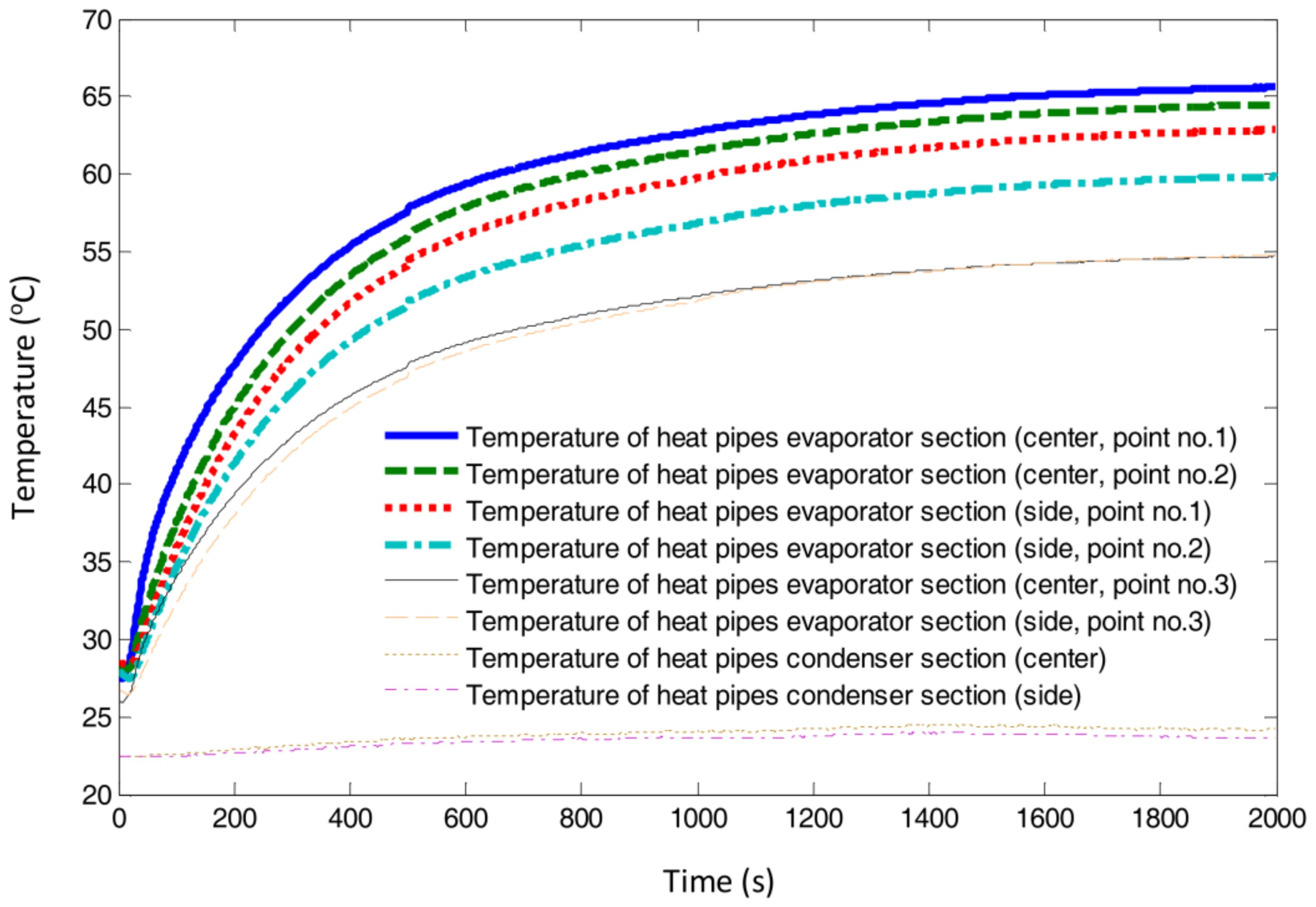
Figure 5.
Temperature as a function of time in the evaporator and the condenser section of the heat pipes (diameter of 6 mm, effective length of 190 mm and pressed thickness of 2 mm and width of 8.50 mm at the evaporator section) in different locations (gravity orientation) using heat supply of 55 W.
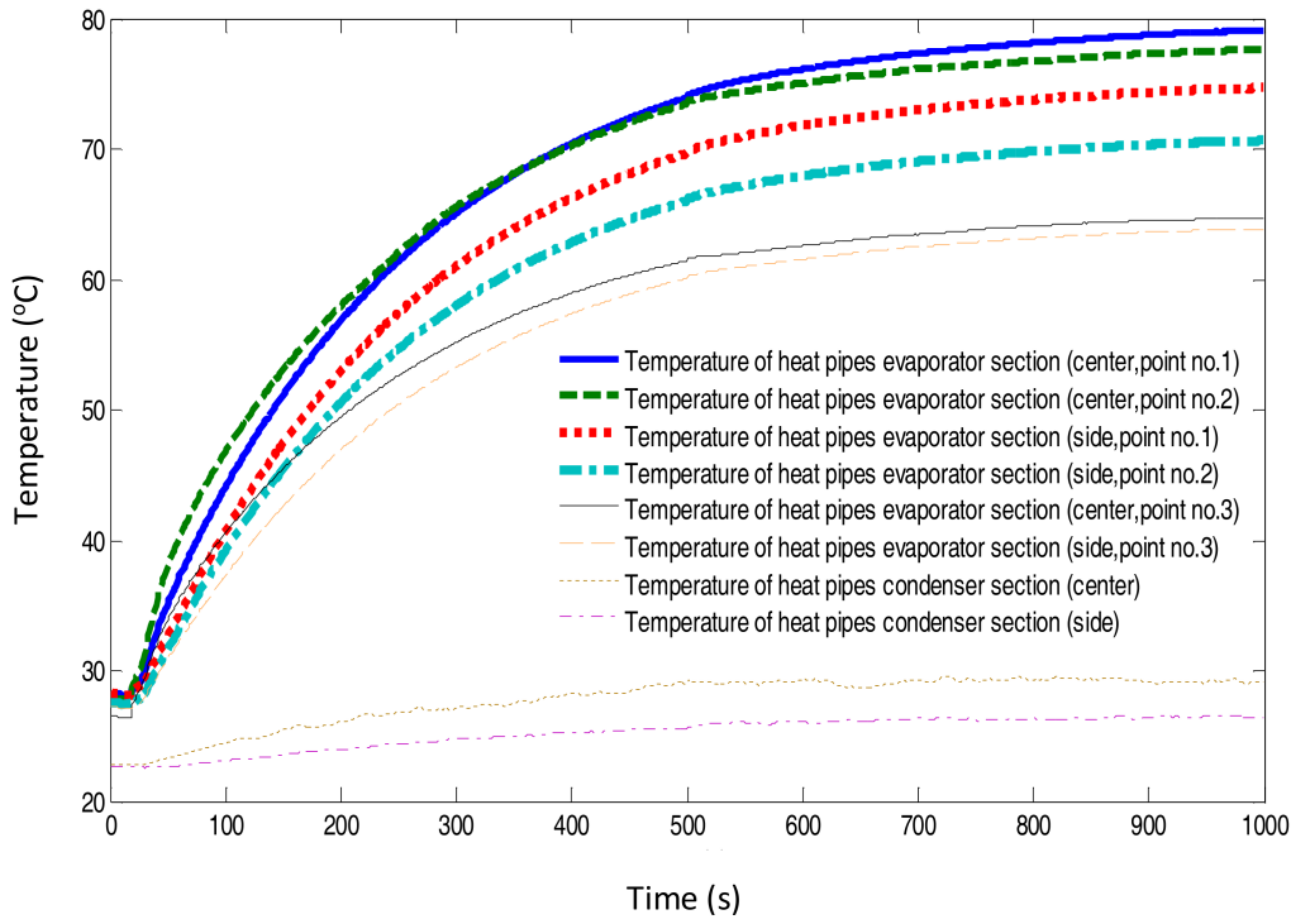
Figure 6.
Temperature as a function of time in the evaporator and the condenser section of the heat pipes (diameter of 6 mm, effective length of 190 mm pressed thickness of 2 mm and width of 8.50 mm at the evaporator section) in different locations (against gravity orientation). The error of 1% was associated with the results using the heat supply rate of 55 W.

Figure 7.
Steady temperature of the heat pipes evaporator sections (diameter of 6 mm, effective length of 190 mm pressed thickness of 2 mm and width of 8.50 mm at the evaporator section) as a function of heat supplied by a DC power supply for gravity and against gravity orientations (maximum 1% error is associated with the data for temperature).

Figure 8.
Effective thermal conductivity and thermal resistance of heat pipes (diameter of 6 mm, effective length of 190 mm pressed thickness of 2 mm and width of 8.50 mm at the evaporator section) as a function of heat supplied by a DC power supply for two different orientations (gravity and against gravity); maximum 1.5% error is associated with the data for thermal resistance and 2% error associated with the thermal conductivity values.

Figure 9.
Hydrogen discharge rate in MH canister (MmNiMnCo, 800 sl) and the temperature of the MH canister as a function of discharging time (experimental); maximum 1% error is associated with the data for flow rate and 1% error associated with temperature.
Figure 9.
Hydrogen discharge rate in MH canister (MmNiMnCo, 800 sl) and the temperature of the MH canister as a function of discharging time (experimental); maximum 1% error is associated with the data for flow rate and 1% error associated with temperature.

Figure 10.
Hydrogen discharge rate in MH canister (MmNiMnCo, 800 sl) and heat demanded by the MH as a function of MH temperature in both the experiments and the model; maximum 1% error is associated with the data for flow rate and 1.5% error associated with heat demanded.
Figure 10.
Hydrogen discharge rate in MH canister (MmNiMnCo, 800 sl) and heat demanded by the MH as a function of MH temperature in both the experiments and the model; maximum 1% error is associated with the data for flow rate and 1.5% error associated with heat demanded.
© 2018 by the authors. Licensee MDPI, Basel, Switzerland. This article is an open access article distributed under the terms and conditions of the Creative Commons Attribution (CC BY) license (http://creativecommons.org/licenses/by/4.0/).
Share and Cite
MDPI and ACS Style
P. Tetuko, A.; Shabani, B.; Andrews, J. Passive Fuel Cell Heat Recovery Using Heat Pipes to Enhance Metal Hydride Canisters Hydrogen Discharge Rate: An Experimental Simulation. Energies 2018, 11, 915. https://doi.org/10.3390/en11040915
AMA Style
P. Tetuko A, Shabani B, Andrews J. Passive Fuel Cell Heat Recovery Using Heat Pipes to Enhance Metal Hydride Canisters Hydrogen Discharge Rate: An Experimental Simulation. Energies. 2018; 11(4):915. https://doi.org/10.3390/en11040915
Chicago/Turabian StyleP. Tetuko, Anggito, Bahman Shabani, and John Andrews. 2018. "Passive Fuel Cell Heat Recovery Using Heat Pipes to Enhance Metal Hydride Canisters Hydrogen Discharge Rate: An Experimental Simulation" Energies 11, no. 4: 915. https://doi.org/10.3390/en11040915
Note that from the first issue of 2016, this journal uses article numbers instead of page numbers. See further details here.