1. Introduction
In the 1940s, Europe clearly defined the problem that existing construction methods cannot meet quantitatively or economically the current needs of post-war housing demand. In the 60s, the state of former Yugoslavia had the urgent issue to rebuild a devastated housing area. Before 1960, almost the only technology applied for housing construction was “cast in place” concrete with large panels. At the moment of rapid housing re-building the building strategy had been set up to ensure the next main issues: lower construction costs, short delivery time, control of building process, narrow and clear specialized job, avoiding mistakes, avoiding complexity [
1]. Traditional building process with massive “cast in place” walls couldn’t work according to demand and time conditions because of the complexity of building process, a number of non-qualified workers, complex workout on the site, long time schedules, non-sufficient economical support, to many construction errors dealing with complex relations between different building function and corresponding technical systems. According to the need for flexibility and simplicity of construction process, buildings have been segmented according to main building parts: load-bearing system, façade, interior walls and supply systems. That was the first transition from “closed” concrete “cast in place structure” where components rely on each other by mixed functions and fixed connections to “open” prefabrication through detachment and independence of different systems and components. “Building in the system” was replaced with new housing building model “with the systems” [
2] (pp. 1–10). Division of the building process by independent technologies set up the first systems’ configuration for massive housing: load-bearing system (primary construction) and façade system (secondary construction). Jugomont, IMS Žeželj, Rad-Balency, Ratko Mitrović, Neimar NS 71, Trudbenik, and many other companies fabricated prefabricated and semi-prefabricated systems and components for housing [
2,
3].
Nowadays, “prefabricated city” is a place of many dilemmas on the social, economic, technological and spatial level. Although representing true technological values for a new stage of energy efficient retrofitting. The devastating processes and procedures are being enabled and encouraged, making it impossible to approach many issues that arose meanwhile: the problem is sustainable renovation, energy management, infrastructure reconstruction. The New Belgrade represents the city of post-war social housing where some 250,000 inhabitants live on more than 4000 hectares. It was planned as a modern city to be the administrative center of New Yugoslavia, but the post-war demand for dwellings and new incoming populations turned the plan from “administrative city” to “city of housing”, as a consequence of the political and economic crisis [
4]. Prefabricated systems found their use in almost every housing project between 1960 and 1985. “Open” technology of prefabricated construction became one of the country’s most successful products. The country was exporting and importing new prefabricated systems, which resulted with more than 20 prefabricated mixed housing systems enabling never before seen growth of the cities at the time—both in space, inhabitants, income, etc. Compatibility issue between systems’ components of different fabricants made it easier for engineers at composing of housing building model. Construction process with IMS industrialized components resulted in a variety of housing layouts presented in
Figure 1. This IBM housing is a perfect “support” layout for the new “infills” [
5]. New technology rules for energy efficient retrofitting infill will be defined for individual unit retrofitting process evaluating different materials, technologies and systems which might be integrated in dwellings retrofitting to provide energy savings [
6].
However, changing spatial configurations in the current structural conception of buildings currently still means a material consuming and expensive intervention [
8,
9]. Highlights on dependency conditions between components and systems in the building model on the functional and technical level will determinate the level of individual unit dependency in IBM. Energy efficiency aspect of industrialized housing will be studied from structural flexibility for integration of energy efficient system at the infill level. A new kind of business entity with a new customer value proposition is needed to meet the demand of variable dwellings for massive housing upgrading [
9,
10]. Design decisions regarding the selection and subsequent integration of energy savings building components need careful consideration during the building model analysis. The central goal is the development of a strategy to provide support for both: the massive housing retrofitting process; decisions regarding the selection of energy savings building components and accordingly, acceleration of industrialized energy efficiency [
11].
Current research in this field covers various energy savings measures, works developing assessment methodologies for housing renovation, and research for energy saving and reducing CO
2 emission in the existing housing stock. According to Energy Efficiency in Buildings in the Contracting Parties of the Energy Community (Final reports, Energy Efficiency in Buildings in the Contracting Parties of the Energy Community,
http://www.buildup.eu/en/practices/publications/study-energy-efficiency-buildings-contracting-parties-energy-community, 24 February 2012) [
12] the best practice technologies in connection to housing retrofits and energy efficient renovation are: (i) high envelope performance (insulations of façades, roofs, top ceilings, ground floors, double glazing windows with polyvinyl (PVC) frame; renovation of balconies and entrances); (ii) air-tight constructions; (iii) double façades and glazed areas; (iv) heat recovery ventilation system; (v) condensing boiler; (vi) district heating systems with low losses; (vii) improving heating systems (combined heat and power, insulation of distribution pipes); (viii) heat pumps; (ix) natural, hybrid and PV-assisted ventilation; (x) solar domestic hot water (DHW) heating system; solar wall and air collectors; PV-installations [
13]. In this research will be analyzed IMS housing up to 23 floors, 400 dwellings per building and different spatial shames of dwellings illustrated in
Figure 1. According to the current housing regulations and the economy situation in Serbia, general refurbishment of massive housing wouldn’t be possible. That is the reason for new approach of infill industry.
The analysis of energy—efficient housing retrofits evidence in addressing both: the building model analysis process and energy saving components selection process. As long as selection of energy saving building components takes place in an intuitive manner there will not be potential for industry efficiency.
1.1. Integrated Refurbishment Scenario (IRS)
Integrated refurbishment scenario (IRS) represents different retrofit technologies suitable for housing refurbishment. IRS consists of methods, tools, techniques, energy-efficient measures and renewable energy technologies—for housing retrofitting. The retrofit technologies from
Figure 2 are energy conservation measures (ECMs) used to promote building energy efficiency and sustainability [
14]. Retrofit technologies range from the use of energy efficient equipment, advanced control and renewable energy systems to the changes of energy consuming patterns, and the application of advanced heating and cooling technologies. We will study building retrofit technologies in correlation with building model composition. Instead of one scenario for whole building, more individual scenarios of different retrofit technologies will be defined according the requirements of every single building. In this research we will propose refurbishment cinereous according to industrialized building model analysis. Schmidt, Deamer and Austin [
15,
16], propose a Design Structural Matrix DSM model with the capacity to compactly model a new building’s product architecture, hence illustrating how well a proposed design can respond to change, through the clustering of modules and observing of dependency relationships in and outside a module.
1.2. Principles for Massive Housing RE-Industrialization
The construction companies implemented the technology of prefabricated construction for every housing project from 1960s in New Belgrade. Industrialization of housing construction gradually replaced the traditional systems with prefabricated and semi-prefabricated systems. The prefabricated systems’ engineers didn’t insist upon the consistency of the system, especially if meeting the demand, deadlines and costs would rise [
1].
By modernizing the technology and applying industrial construction methods building structure become a prefabricated systems’ configuration of two technologically independent parts: load-bearing structure and building envelope. Partition walls and different supply systems have been installed independently from load-bearing level. Different Yugoslav construction technologies have been developed by industry to control and to satisfy flexibility performance of the systems’ building process. Massive structure become a systems’ configuration model of primary construction (load-bearing system) and secondary construction (envelope system) [
2].
Approaches to reuse the existing buildings need to intervene in a way that these buildings can again participate in a positive environmental development. As infill industry development increases, an accent will be on dwelling unit retrofitting independently from building model retrofit processes. Therefore an analysis approach is proposed for the renovation process of housing supporting the structural model flexibility on different technical levels while minimizing its environmental impacts. The proposal makes use of the existing bearing structure a “support” with empty plots for a new adaptable “infill” [
17], independent of the old structure. Flexibility value of systems’ model will be tested for integration of energy efficient systems with the special emphases for the potential benefit of new infill industry development toward massive housing rehabilitation from “inside”.
2. Open Technology of Prefabricated Construction
The main feature of “open” systems’ configuration for massive housing in Beograd is flexibility—the possibility of adapting production for different elements’ assemblies for different building parts. Constructors started to design flexible structure consisting in load-bearing system and envelope system together with architects to build the “support” [
18] according to the needs of the particular architectural design. Housing design had become a design and building of more flexible “support” [
19]. Transition from solid model to “open” model underlined new era for systems’ assembling according to different building functions. Different technologies started to be developed for load-bearing systems and envelope systems. In the further development of the prefabrication technology, the construction production was divided into the elements of primary construction and those of the secondary construction or façades, which made things easier in coordination between building structure and architectural design. Further development of the building industry was defined with full prefabrication and thus a complete industrialization of production of all elements belonging to primary and secondary constructions [
20]. This kind of systematic approach of building parts into systems’ configuration has been approved by open prefabrication of the individual systems and components. The most significant fabricant was IMS Institute for prestressed concrete skeleton frame (IMS system).
“Open” Technology of IMS Housing Model
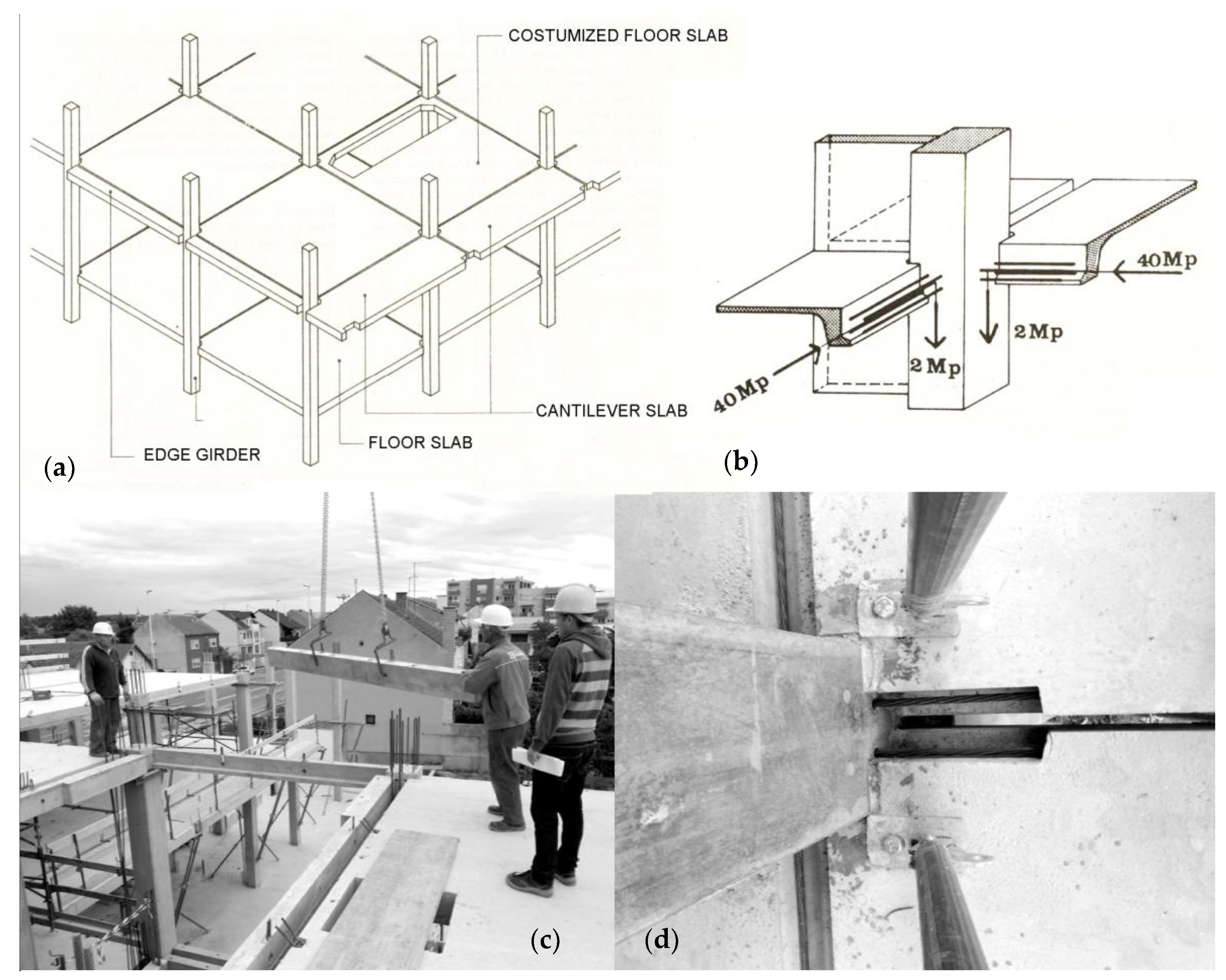
Analysis of IMS buildings by its decomposition on systems and components is possible according to independence of different technical levels. Instead of breaking down the parts of the structure, systems approach works by mapping larger groups of interacting elements and supports analytical method for in-between relations. Systematic approach and independent technical levels is applied for open hierarchy assemblies where load-bearing structure is a higher level and serves as the setting in which lower levels operate. The primary support skeleton is completely separated from façade system, interior partitions and installations (shown in
Figure 3). This situation of independency of different functions and corresponding technical levels is the main flexibility value of “open” prefabrication technology. External walls are designed so that they can be changed when the renovation takes place in the future. That would be possible with interior partitions and some of heating, ventilation and air conditioning HVAC supply systems as well. Future adaptability measures will be questioned for different building levels (facade, interior partitions, supply systems).
IMS support structure is the structural plot where dwelling units design find the place. The IBM building includes primary structure, building envelope (roof and facade), building common area (lobbies, corridors, elevators and public stairs) and primary mechanical and supply systems (electricity, heating and air conditioning telephone, water supply, drainage, gas, etc.).
Finally, the new reconstruction scenario should be planned to support more efficiency of IBM structure by increasing its transformation capacity for the individual dwellings upgrading. For that reason, upgrading the massive structure for more flexibility and adaptability of various functional and technical levels can be seen as a key integrate factor for sustainability of massive housing. The building structure should be analyzed by decomposition method for systematization of different components and subsystems into clusters and the relations between them. Decomposition process according to independency of different parts and performance evaluation value needs to be integrated at an early reconstruction phase.
3. Systematic Approach for Open Prefabrication Technology
3.1. Definition of the Massive Housing Industrialized Building Model (IBM)
We start with analysis of the structural configuration of the integrated prefabricated systems and we put into correlation the following: required adaptability of industrialized buildings on spatial, technical and energy efficiency level and the technological rules and values of the building structure. Industrialized Building Model (IBM) is the systems and component—based model assembled according to the independent functional and technical levels. Considering the level of structural and physical dependency in this type of configuration, we will establish in what measure new integrated energy efficient components, simple and demountable dry joints, low energy incomes, sustainable materials and construction technology innovations; are suitable for refurbishment of massive housing.
Independent technical levels for the components systematization are established according to the principal building functions: load-bearing, servicing, enclosing and partitioning (shown in
Figure 4). Every function has a corresponding technical level where different components and subsystems make physical connections. Technical building levels and conditions for the systems and components connections have a direct influence on the building transformation capacity. The more often a component (subsystem) needs to be replaced, the more accessible it ought to be [
22,
23].
3.2. Configuration Design of IMS Housing Model
The building structure is designed and built as an open systems’ configuration model. All systems and components belong to integrated configuration model arranged according to the main building functions (load-bearing, enclosing, partitioning and servicing). Systematization of industrialized components into independent levels takes into account that different parts of the building have different life span and functional expectances, as well as different assembly procedures. The key aspects of sustainable retrofitting are in the housing ability to be dismantled where the systematization and the hierarchy support total configuration disassembly. Main characteristics of IBM are:
Systems and components are assembled into independent functional and technical levels;
Load-bearing structure is designed and built as IBM;
Isolation of IMS support skeleton assembly allows a number of different “infills” distributions in the future use of IBM;
Possibility to change the surface of the floor plan, either by additional construction or changes in the boundaries of units out of the “support” limits;
Connections between removable parts and load-bearing structure are mechanical joints;
Positioning of services as independent system provide easy access and HVAC system upgrading;
IMS housing is designed with or without cantilever slabs with variable main module to generate diversity in the layouts. The building core contains all important installations: central communications and services (stairs, bathrooms, cleaning rooms, toilets. In that way all the apartments may have two-side orientations. This kind of solution supports the initiative to exploit the maximum of the living space.
3.3. Definition of IMS Graph Model (GM)
Graph Model (GM) diagram is developed to describe the IBM by elements (components, components assemblies, subsystems, systems) as a diagram of relations. Graph model represents relations and dependency condition in massive structure. The GM will be used for further analysis of structural relations that affect the flexibility and transformation capacity of buildings for spatial and technical adaptations.
Figure 5 presents the GM and describes its main parts: nodes, clusters and edges.
GM elements a, b, c, d, e, f from
Figure 5 are nodes—components. Is equivalent to a column of the load-bearing structure, partition wall, or water pipe, etc.
GM elements A, B, C, D are clusters—elements assemblies (components or subsystems) and are equivalent to load-bearing structure (concrete skeleton composed of beams, columns, hollow core slabs).
Edges are different types of connections between different elements in the IBM. They will have the mayor importance in evaluation of dependency conditions in existing massive structures and will be taken into consideration for development of the new retrofitting strategies of the systems’ configuration [
24].
3.4. Graph Model as an Efficient Input for IBM Transformation Capacity Analysis
According to GM diagram different types of connection has been established (
Figure 5) and will be analyzed to evaluate dependency conditions between different parts in IBM housing. Every connection between elements is defined by elements’ interface geometry and type of joint. Analysis of massive structure through relations between various systems and components will highlight dependences between elements and underline flexible structural spots to be used for future deployment of new systems and components. Simple connections between “nodes” and “clusters” allow disassembly in systems’ configuration. Fixed connection between cluster and node is a non-desired “edge” in the structural model configuration. The cluster belongs to higher level in the IBM hierarchy assembly and node is at the lower level that should change more frequently. Any fixed connection between elements placed in different hierarchical levels is a non-desired edge. Fixed connection between two components from different levels is a conflict structural spot when making changes can end up with a major demolitions and waste disposal. Finally, different housing buildings will have different rehabilitations scenario according to dependency conditions between its structural elements analyzed and established by systems’ configuration GM.
4. IMS Building Model: Case-Study Analysis
Each case has been analyzed using an approach consisting of:
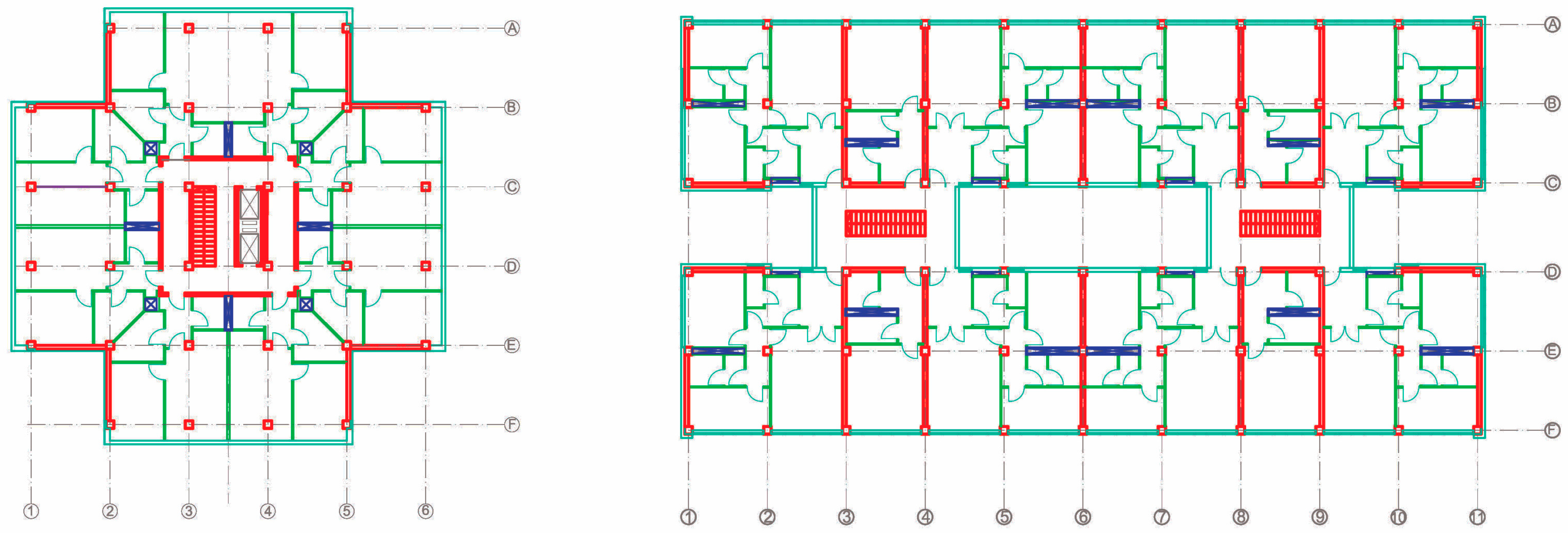
IMS building technology had been applied for almost 90% of post-war housing in Belgrade. IMS standardized components were applied for the complete building model (columns, slabs, edge girders, cantilever slabs, stairs, shear walls, roof slabs, balcony fence, façade panels, parapets, stairs and industrialized sanitary blocks). The territory of Block 1 and 2 (later block 21) in New Belgrade was the first experimental site where the IMS building technology had been experimented for a first tower building B + 14 and corridor building B + 4 (shown in
Figure 6). On
Figure 6 different colors represent different functional and technical levels (load-bearing system/red, envelope/light blue, partitions/green and services/dark blue).
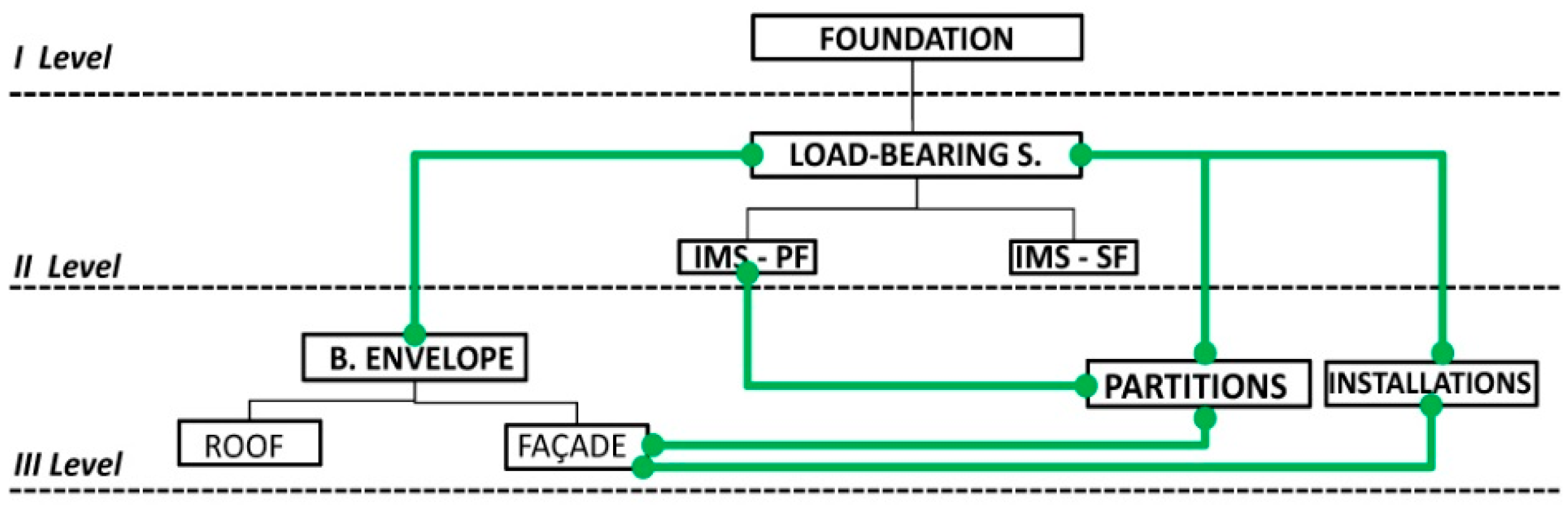
Figure 7 presents general systematization of IMS post-war housing buildings into three independent levels.
The first level is foundation concrete slab on steel piles used to transfer the loads from superstructure down through upper weak layer of topsoil to the stronger. The load-bearing superstructure is independent of the other clusters and corresponding components on the second level. On the third level are placed envelope subsystems and components, partition walls, installation systems for heating, electricity, water and drainage.
The green edges are flexible connections of mechanical joints (façade/IMS skeleton; IMS skeleton/partitions; IMS skeleton/supply systems; façade/partitions; façade/installations—shown in
Figure 7). These flexible edges will be used for planning a refurbishment scenario for the envelope, services and functional changes of dwellings. According to the different types of connections façade cladding subsystem is more suitable for transformation. More specifically are well examined the type of edge/joint between the components from different technical levels. In
Figure 8 is presented the decomposition of IMS building model for the different housing typologies (tower and condominium building).
The load-bearing structure is a skeleton frame with the shear walls for horizontal loads. There are two clusters of components on the load-bearing level: the primary structure—skeleton frame and the secondary structure—shear walls. Shear walls belong to one technical level but deal with more functions; therefore, they are technologically dependent and not suitable for transformations. GM of four main clusters is developed and corresponding nudes are systematized into four main technical levels (
Figure 9).
According to the graph model in
Figure 9 two types of connections are detected. Red edges are fixed connections between IMS components separated in two clusters: the primary frame (columns/slab/shear walls) and secondary frame (edge girder/cantilever slab). Fixed edges IP-GS, IP-EC, IP-WS—are the connections between water pipes and wires embedded in non-load-bearing partition walls and slab components (Cc).
The green edges are flexible-mechanical joints and will be used for integration of new retrofitting components and systems. In terms of cluster-edge relations we have transformable PW-EG (parapet-edge girder) edges between the components that belong to clusters from different levels (
Figure 10). Any transformation of the PW components will not affects the EG component even if the edge girder is a component from the load-bearing cluster and parapet belongs to the envelope cluster in the third level. Bearing in mind the level of a functional, structural and physical domain in the IBM, new retrofitting components will be integrated according to the green edges by simple and demountable dry joints.
Further development of the IMS housing was a tall tower building up to 23 floors. Building 06 B2 from the block No. 63 is shown on
Figure 11. The IMS construction building technology is applied for load-bearing system with the construction span 3.60 m × 5.40 m. Building in block 63 is 16 floors high with 348 flats and 20.088 m
2 net surface area. A square column 38 × 38 cm is applied in the object A-16 but in lower buildings a column of 34/34 cm is adopted. IBM structure consists of 5 independent parts: IMS skeleton, shear walls, roof construction, façade cladding and interior partitions. The shear walls for horizontal loads are reinforced concrete elements cast on site up to 12 floors, and then prefabricated components (up to 20 floors).
GM from
Figure 12 represents major subsystems are independent. Demountable-mechanical joints (façade panels and load-bearing system; partitions and load-bearing system, partitions and installations; installation and load-bearing system) may be refurbished on different levels of its composition. The interior partition can exchange its position for functional changes and spatial upgrading. The space around the sanitary blocks is flexible.
The first tower buildings from block No. 1 and 2 was further developed into more flexible housing layout in the block No. 70 (shown in
Figure 13). Tower buildings are square (with a variable perimeter) with different height: from B + 8, up to 14 floors. Different building typologies are characterized with different floor height and dwellings’ layout.
The shear walls for the horizontal loads are prefabricated 20 cm thick components. Position for the shear walls is fixed in the building layout. IMS structural span is 3.60 m and 4.20 m. In
Figure 14 could be observed a completely flexible housing layout and façade perimeter line. Façade perimeter line runs outside or inside the last columns line, thus creating dynamics and diversity of the interior space. All interior partitions are non-bearing components of metal studs with plaster board cover.
The typical façade solution of horizontal parapets and windows was replaced with industrialized panels, with all windows and doors preinstalled on the production line. A panel thickness is about 18 to 30 cm. A complete façade panel is composed of a parapet wall, window and columns between windows. All openings were preinstalled before the panel erection. The solid façade panels are industrialized components working as the shear walls for horizontal loads. Façade cladding is supported floor to floor by semi-mechanical joints (shown in
Figure 15).
The building lifts’ cores are prefabricated elements too. The components were executed from 10 cm thick prefabricated panels. Loggia panels were fabricated in different building technologies as they didn’t have contact with the outside weather conditions. Sanitary block is an industrialized block. Managing the installation pipes and ducts through the holes in the cassette floor slab was very common. The IMS floor slab was easy to adapt, providing only a necessary holes for sanitary blocks connection (show in
Figure 16). The maximum size of the holes in one cassette was 70 × 70 cm.
5. Discussion and Outcomes of the IBM Transformation Capacity
The integration of retrofitting measures defines a method for massive housing refurbishment to be based on more flexible edges according to IBM analysis. Main principles for the sustainable retrofitting and transformation of industrialized housing are:
5.1. IBM Transformation Capacity Stands on Components and Systems Hierarchy Assembly
Components and systems hierarchy assembly in the IBM takes into account that different parts of the IMS structure have different lifetime and functional expectances. Adaptability at the component’s level is possible according to the compatibility issue and mechanical joints. This internal hierarchy determines relations between different industrialized component and subsystems, and therefore, the easiness or difficulty for upgrading process. According to GM mechanical joints between interior walls and IMS primary structure skeleton frame is proposed development and implementation of the new ‘infill’ industry for massive housing retrofitting.
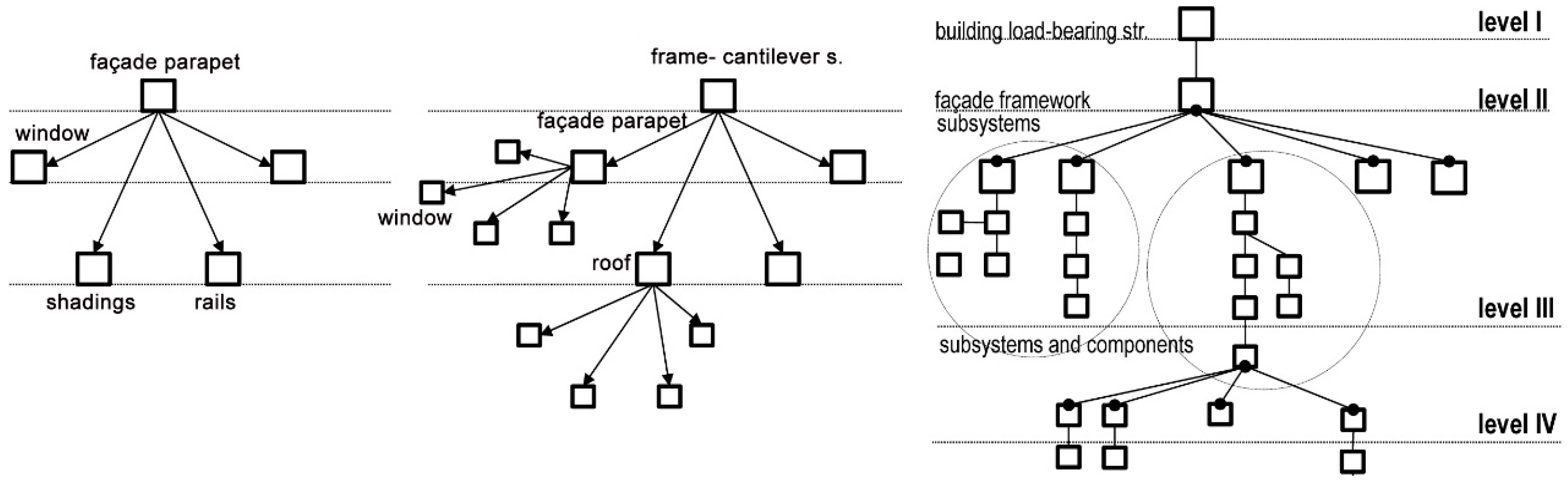
In the IMS model hierarchy, the independent systems have one base element for making connection with other components and subsystems in the hierarchy (shown in
Figure 17). The edge girder or cantilever slab is the base element for all elements of parapet and window cluster (windows’ wings, shadings, rails). Systematic approach for building structure through the base elements and their connecting parts stands for a better control of the IBM structure, use of exchangeable parts, and future disassembly at the end of the service life.
5.2. IBM Transformation Capacity Is Based on the Simple Joints and Interface Geometry in Connections
Components interface geometry and type of joint in model edges are the principal conditions for the IMS building model transformation capacity. Flexible connections allow for planning changes without usual demolition of building parts associated with renovation. In order to evaluate the building structure transformation capacity, two types of relations have been examined: one between the clusters/subsystems (façade, roof, partition walls and services) and within clusters. The simplest edges are found in the façade cluster, between façade and load-bearing components and flexible edges between partitions and IMS skeleton frame. The mechanical joints will be used for the system upgrading by integration of the energy efficient components and systems.
5.3. IBM Transformation Capacity Depends on Functional Decomposition and Independent Technical Levels
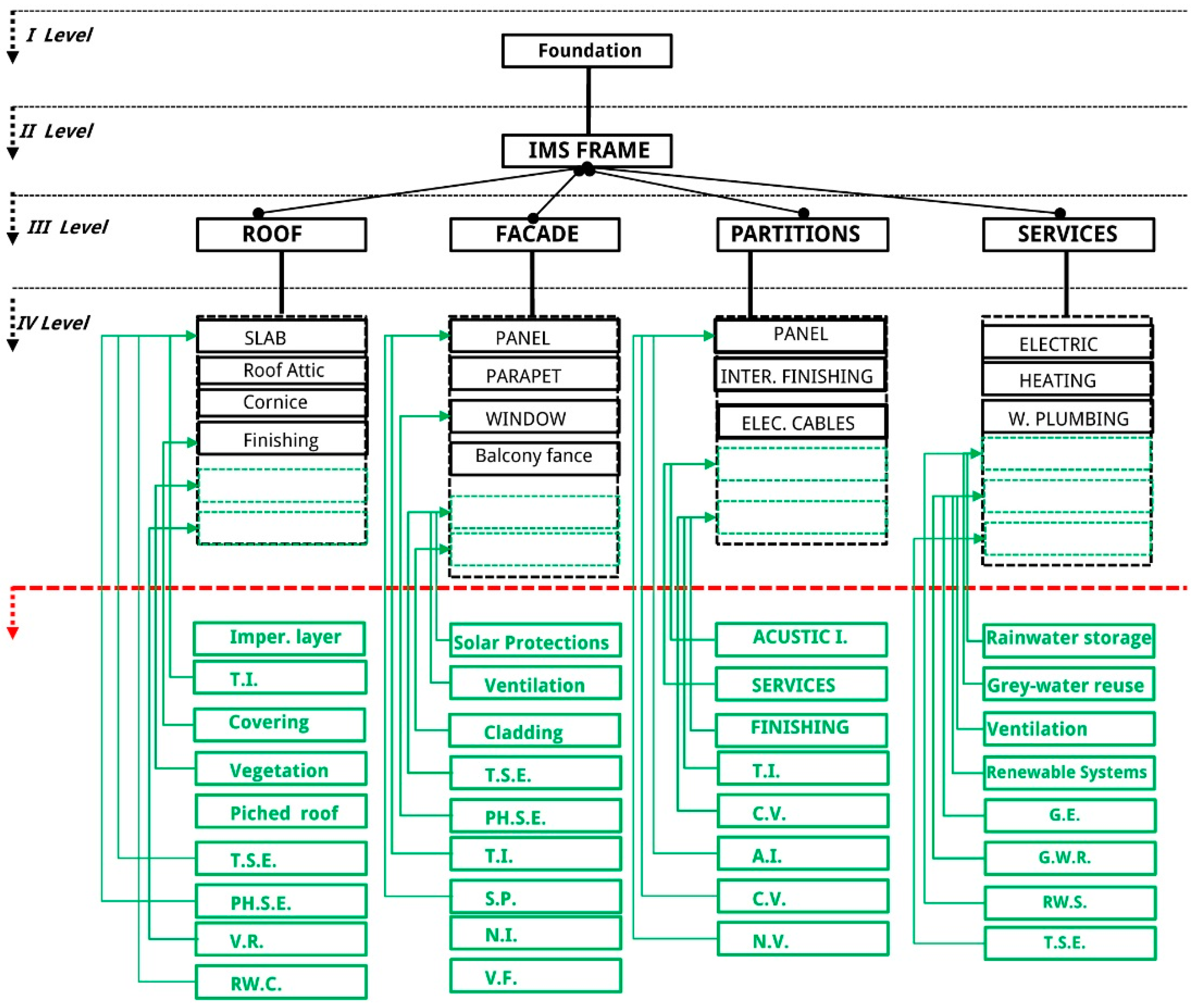
IMS Industrialized housing models are designed and built according to functional decomposition of major systems and corresponding components. From the study, we can conclude that the IMS housing models are suitable for integration of new systems and components at the infill level. The three technical levels and the main functional systems on each level are independent. The load-bearing structure is higher level and is the ‘lot’ in which lower levels operate and can make changes. On the fourth level there are components that will change with more frequency. All green filed from the
Figure 18 represent energy efficient measures, systems and components to be applied for the housing refurbishment in the future.
5.4. How the IMS System Solved the Reinforced Masonry Construction Problem?
The process of designing and constructing buildings was “open” and its participants cooperated very actively, often reaching specific technological solutions to adapt to the needs of individual design. Design of the building structure was possible according to the modifications and transformation of the IMS components assembly. IMS structural span evolved from a 3.60 m span (Block 21, Building B9) to that of 7.20 m, with 2.10 m consoles (for the district Cerak Vinogradi). Every new housing building is a new customized application of IMS system. The determined number of IMS structural components and simple mechanical joints create open hierarchy assembles suitable for further upgrading process on the different level of its composition.
We can emphasize that Yugoslav building industry has created a methodology for systematic building approach by division of IBM according to main building functions. Yugoslav industry set its own systematic approach on this prefabricated model, considering prefabrication a multidisciplinary approach in which all professions would have an equal share. Until the mid-1980s, the performance of 57 local and foreign systems was applied for different building parts, 20 of which were extensively used. Flexibility of IBM design and permanent technological improvement became the main strength of IMS building technology in the international market.
6. Conclusions
Dependency conditions of subsystems and components in IMS hierarchy assembly allow for IBM to be approved with additional components and subsystems at the infill level. The systematization of independent and interchangeable components of interior panels by demountable joints approaches the new ‘infill’ industry for massive housing retrofitting at the dwelling level. Various energy-efficient subsystems and components will be adjusted with improved autonomy for individual dwellings. The main features of the IBM are:
Separation of technical levels according to main building functions.
Hierarchy assembly of distinct subsystems and components.
Simple mechanical joints between components.
These measures will be applied for an integration of new systems and components to the existing housing models for its sustainable refurbishment. Industrialized BM refurbishment scenario will be based on: spatial and technical transformations; passive, active and renewable energy retrofitting. A significant innovation will be required for designing the appropriate physical interfaces and connections between components to ensure future transformation capacity. Therefore, future integration of systems and components should generally address assembly and disassembly of systems and components. The GM will be applied for the future integration of flexible and demountable systems to upgrade post-war housing on the spatial, technical and environmental level. Future research will continue to focus on:
Development of the infill industry regulations with many competitive players with an emphasis on the threats of simple and demountable connections between industrialized components.
Collaborative BIM project model of different parties (tenants, technology providers, construction companies, researchers…) to demonstrate a successful method for deep retrofit with the potential for large-scale replication.
IMS Building Model supports the approach for integration of infill level as an opportunity for the industry to offer new sustainable products for massive housing retrofitting based on IBM transformation capacity. According to IBM analysis GM diagrams show that building supply systems are more dependent components and systems in the massive structure. A new retrofitting scenario will drive the building industry toward the development of efficient retrofitting infill technologies. Planning the retrofitting scenario consists in different efficient technologies and industrialized measures arranged for every single building. This conceptual word describes the future GM diagram of retrofitting measures provided from IBM analysis and dependences conditions from GM diagram of existing massive models. Buildings designed as the systems’ configurations with independent systems can create conditions for adaptability in different time and by different parties. Subdivision can then be translated into the specifications for connections (type of joint between parts) to be integrated later on. Evidently, one of the potentials is possibility to integrate new infill set of functions and corresponding technical systems, in some cases with no demolition at all, according to main IMS system advantages:
Design, composition, dimensions, and location of structural components into independent functional and technical levels;
IMS concrete skeleton designed and built as flexible system enables flexible solutions, greater space-planning capabilities and a wider range of possibilities for building interior design (open systems’ prefabrication);
Isolation of load-bearing assembly as independent technical level allows a number of different layouts and customized solution for the facade modeling;
Possibility to change the floor layout, either by additional construction outside the boundaries of the façade or changes in the boundaries of units out of the support limits.
Energy use in the residential sector can be reduced if the dwelling is retrofitted from inside.
Energy saving while reducing the waste is possible with infill retrofitting.
In future work, we will upgrade the Graph Model using DOT (Draph Description Language) for faster transition of IBM into cluster-node-edge dependency diagram. DOT is a plain text graph description language. It is a way of describing “graphs” as a representation of a set of objects where some pairs of objects are connected by “links” (
https://en.wikipedia.org/wiki/Graph_%28mathematics%29). In our case, the objects are nodes and clusters, and the links are edges. Finally, GM scrip and Building Information Modeling (BIM) will be compiled for the rational description of the current state of the IMS massive housing outlining the sustainable energy retrofits.


