Article

Electromagnetic Characteristics Analysis of a High-Temperature Superconducting Field-Modulation Double-Stator Machine with Stationary Seal

1
College of Information and Control Engineering, China University of Petroleum, Qingdao 266580, China
2
School of Electrical Engineering, Southeast University, Nanjing 210096, China
*
Author to whom correspondence should be addressed.
Energies 2018, 11(5), 1269; https://doi.org/10.3390/en11051269
Submission received: 16 April 2018 / Revised: 12 May 2018 / Accepted: 14 May 2018 / Published: 16 May 2018

Abstract

:
This paper has proposed a high temperature superconducting (HTS) field-modulation double-stator (HTS-FMDS) machine with a stationary seal for low-speed and direct-drive applications. The originality of this paper lies in the HTS field-excitation windings, which were fed with a direct current in order to offer strong field excitation, were placed in the inner stator, while the armature windings were installed in the outer stator so that the stationary seal of the cryogenic cooling system could be achieved. Moreover, a ferromagnetic ring was mounted on the top of each HTS coil to prevent the quench of the HTS wires resulting from the armature-reaction magnetic-field. By using finite-element analysis (FEA), the influence of the armature-reaction magnetic-field on the critical current and the electromagnetic properties were carried out so as to verify the validity of the proposed machine.

1. Introduction

In the past decades, superconducting machines have attracted widespread attention in high-power, low-speed, and direct-drive applications, such as marine propulsion and wind power generation, because of their significant advantages of high efficiency and high power/torque density [1,2,3]. Generally, in order to take full advantage of the high critical-current characteristic of the superconducting wires, the field-excitation windings, which were wound with superconducting wires and mounted on the rotating rotor side, were fed with a direct current so as to offer a strong magnetic field [4,5]. Therefore, the coupling device for a cryogenic transfer of this kind of superconducting machine was installed between the rotating rotor and stationary cryogenic refrigeration system, in order to realize the circulation of the refrigeration coolant in the cooling system [6,7]. However, this kind of superconducting machine with a rotating seal undoubtedly increases the manufacturing cost and reduces the operational reliability of the cryogenic refrigeration system.
In recent years, borrowing the idea of setting a magnetomotive force (MMF) source in the stator side of stator-excitation machines, such as flux-switching machine and flux-reversal machine [8,9,10,11,12,13], a kind of high-temperature superconducting (HTS) machine with a stationary seal was proposed and investigated [14,15,16]. Since their HTS field-excitation windings are installed in the stator side, the coupling device for cryogenic transfer can be removed, hence transforming the rotating seal into a stationary seal and simplifying the structure of the cooling system. However, since both the armature windings and the HTS field-excitation windings are located on the same stator, the HTS field-excitation windings will be exposed to the applied armature-reaction magnetic-field when the machines run with loadings. Accordingly, the alternate armature-reaction magnetic-field will directly act on the HTS wires and thus cause hysteresis loss in the HTS wires. If the hysteresis loss is greater than the minimum quench energies (MQE), it will lead to the quench, which means that the superconductor changes into a normal conductor, of the superconducting wire. Therefore, it is urgent to solve the problem of the quench of the superconducting wire that is caused by the armature-reaction magnetic-field of the HTS machines with a stationary seal.
For this purpose, this paper has proposed an HTS field-modulated double-stator (HTS-FMDS) machine with a stationary seal, which can prevent the quench that is caused by the armature-reaction magnetic-field for low-speed direct-drive applications. The proposed machine not only achieved the stationary seal of the cooling system, but also prevented the quench resulting from alternating the armature-reaction magnetic-field, hence reducing the manufacturing cost and improving the operational reliability of the machine. In Section 2, the configuration and operation principles of the proposed machine are discussed. Section 3 focuses on the influence of armature-reaction magnetic-field on the critical current. Then, in Section 4, the electromagnetic properties of the proposed machine are presented and analyzed. Finally, some conclusions are drawn in Section 5.

2. Topology and Operating Principle

2.1. Topology

As shown in Figure 1a, the proposed HTS-FMDS machine mainly includes an outer stator, a modulation-ring rotor, a ferromagnetic ring, and an inner stator from the outside to the inside. The outer stator has 42 slots and the number of pole-pairs of the three-phase armature-windings is 14. While the HTS field-excitation windings with four pairs of magnetic poles are placed on the inner stator side, so that the armature windings and the HTS field-excitation windings are located in two spatially independent stator. In order to modulate both the internal and external air-gap magnetic-field and transmit electromagnetic torque, a modulation-ring rotor, which consists of 18 ferromagnetic blocks, is mounted between the inner and outer stators. In addition, for the purpose of facilitating the installation of the cooling system, the HTS field-excitation coils and their cooling Dewars, which accommodate the HTS coils, are all designed to be racetrack-shaped, as shown in Figure 1b. It should be particularly noted that the ferromagnetic ring, which is located on the top of the field-excitation magnetic poles, not only provides a magnetic circuit for the field-excitation magnetic field, but also guides a path for the armature-reaction magnetic field, as shown in Figure 2. Thus, the armature-reaction magnetic field does not directly act on the surface of the HTS coils. Accordingly, the quench that is resulted from the armature-reaction magnetic field can be avoided.

2.2. Operating Principle

Assuming that the outer stator adopts a closed slot stator construction, the influence of the alternation between the outer stator slots and stator teeth on the air-gap magnetic-field can be ignored. According to the general theory of magnetic-field modulation [17,18,19,20,21,22], the magnetic field that is excited by the HTS field-excitation windings will be statically modulated by the inner stator teeth. The number of pole pairs of the modulated magnetic field can be obtained as follows:
P s = ( 2 i 1 ) P H T S
where PHTS and PS are the number of pole pairs of the HTS excitation magnetic-field and the modulated magnetic-field by inner-stator teeth, respectively; i is a positive integer, namely, i = 1, 2, 3, …, ∞. Then, the aforementioned magnetic-field will be further modulated by the rotating modulation-ring rotor. The number of pole pairs Ph and the rotational speed ωh of this magnetic field can be calculated as follows [23,24,25]:
P h = | ( 2 i 1 ) P H T S + j N r |
ω h = j N r ( 2 i 1 ) P H T S + j N r ω r
where Nr and ωr are the number of ferromagnetic modulation-blocks of rotor and rotational speed, respectively; j is a integer, namely, 0, ±1, ±2, …, ±∞.
In order to further clarify the operating principle of the proposed HTS machine with a stationary seal, one of the main effective harmonics is taken as an example for specific analysis. The existing literatures have shown that the best modulation effect can be obtained when i = 1, j = −1. Therefore, for the proposed HTS machine, the 14th harmonic is its main effective harmonic. As illustrated in Figure 3, when the modulation-ring rotor rotates for 20 mechanical degrees, the back electromotive force (EMF) that is induced in the armature windings by the 14th effective harmonics, will alternate for an electrical cycle. This phenomenon shows that the sinusoidal back-EMF is induced in the armature windings of the outer stator, since the stationary HTS field-excitation magnetic-field is modulated by the rotating modulation-ring rotor. In this way, the stationary seal of the cryogenic refrigeration system can be achieved.

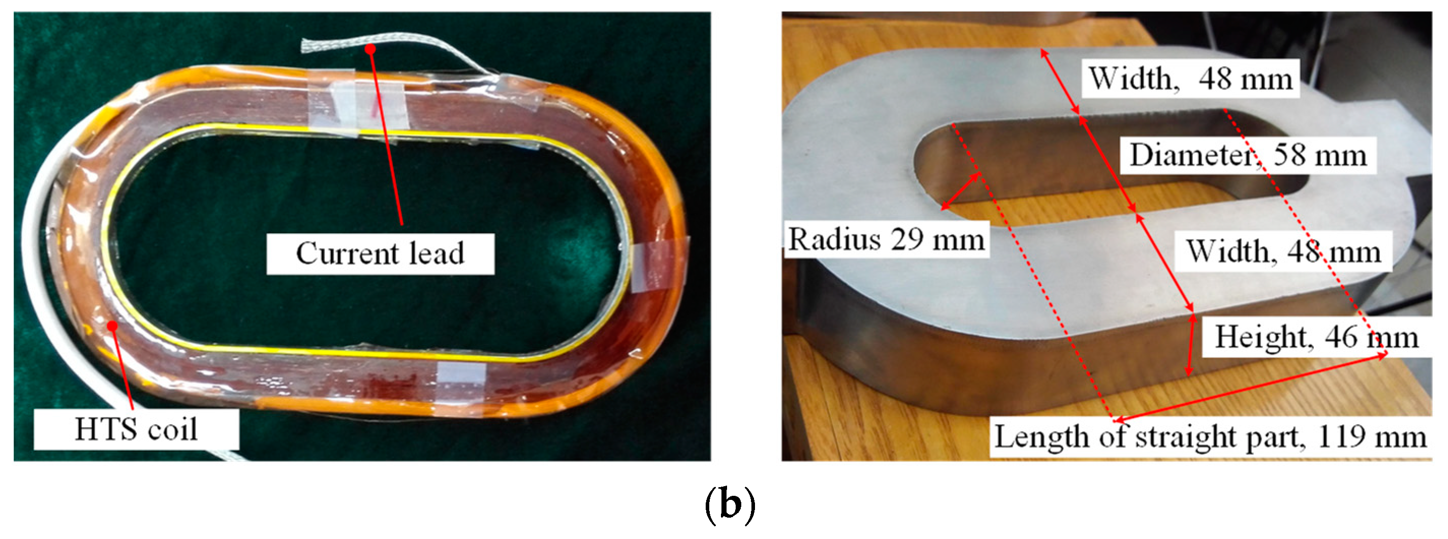
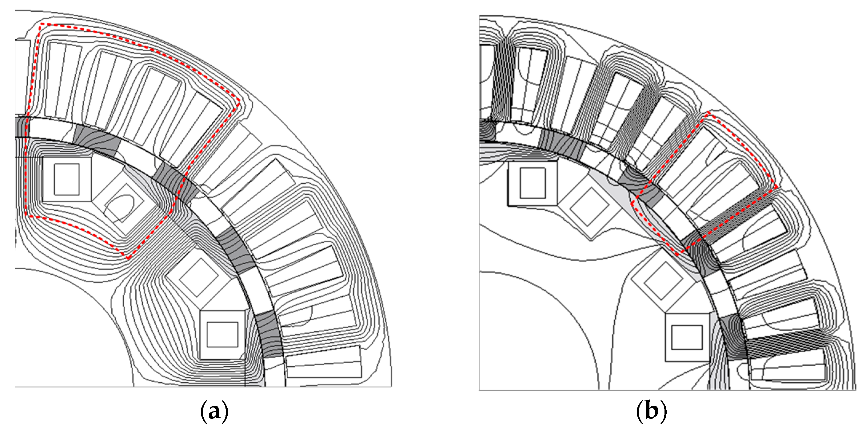
3. Influence of Armature-Reaction Magnetic-Field on the Critical Current

In this paper, the field-excitation windings of the proposed HTS machine were made of BSCCO-2223 HTS wires. Its corresponding main performance parameters under the self-field condition are listed in Table 1. When the proposed machine operates stably, the allowable maximum excitation current that is to be applied to the HTS field-excitation windings is determined by the operating temperature, the armature-reaction magnetic-field, and the corresponding properties of the HTS wires. Therefore, it is necessary to evaluate the shielding effect of the magnetic ring on the armature-reaction magnetic-field, so that the quench that is resulted from the external magnetic-field can be prevented. Then, the rated value of the applied field-excitation current can be determined.
As mentioned before, since the alternating armature-reaction magnetic-field may be applied on the surface of the HTS wires in any direction, the quench of the HTS wires will be caused. Therefore, bow-shaped ferromagnetic blocks, as shown in Figure 4, are mounted on the top of each HTS coil, in order to prevent the quench that is resulted from this externally applied magnetic-field. As depicted in Figure 2b, most of the armature-reaction magnetic-field forms a closed magnetic circuit through these bow-shaped ferromagnetic blocks, which reduces the influence of the armature-reaction magnetic-field on the critical current of the HTS wires. In order to facilitate the processing and assembly, these bow-shaped ferromagnetic blocks are integrated by a thin magnetic bridge with the radial length lb to form a ferromagnetic ring. Generally, the value of the radial length lr determines the magnetic shielding effect of the ferromagnetic ring on the armature-reaction magnetic-field. The larger the value of lr, the better the magnetic shielding effect that can be obtained. However, it will cause a decrease of the power density of the machine. In contrast, if the value of lr is too small, the magnetic shielding effect of the ferromagnetic ring will be reduced, and the critical current of the HTS wires will be suppressed. Therefore, it is necessary to balance the compromise between the magnetic shielding effect and power density of the machine.
For the ferromagnetic ring, its magnetic shielding effect depends on the saturation level of the bow-shaped ferromagnetic blocks. Figure 5 shows the flux density contour plots of point A, B, and C on the inner wall of the cooling Dewar, with and without the rated field-excitation current. It can be found that, when the rated field-excitation current and armature current are applied simultaneously, the magnetic flux density of the ferromagnetic ring is significantly higher than that without the excitation current. The underlying reason is that the magnetic flux density of the ferromagnetic ring is determined only by the armature-reaction magnetic-field when there is no field-excitation current, however the magnetic flux density of the ferromagnetic ring is generated by the combination of both the HTS field-excitation magnetic-field and the armature-reaction magnetic-field, when the field-excitation current is applied to the HTS windings.
Figure 6a illustrates the variation of the magnetic flux density at point A, B, and C in an electrical cycle, when the rated armature current is fed without the field-excitation current. By means of harmonic analysis, the magnetic flux density at each point can be decomposed into a DC component and harmonic components, among which, both the fundamental and harmonic components of point A are higher than those of the other two points, as shown in Figure 6b. The amplitude of the fundamental component of the magnetic flux density is about 2.5 mT, and its other harmonic components are successively reduced. Figure 7 further shows the variation of the magnetic flux density of each point in one electrical cycle, under the rated armature current and field-excitation current. Compared with the condition without the rated field-excitation current, the DC component of the flux density increases significantly up to 135 mT. Furthermore, the amplitude of the corresponding fundamental and harmonic components also increase obviously. The amplitude of its fundamental component reaches 20 mT.
According to the datasheet that has been provided by the manufacturer, the parallel and vertical magnetic-field characteristics of the employed BSCCO-2223 HTS wires under 77 K condition are depicted in Figure 8. It can be seen that, when the applied armature-reaction magnetic-field is perpendicular to the surface of the superconducting wires, namely, the acting angle α is 90°, the critical current Ic drops sharply with the increase of the external magnetic field. When the applied magnetic field reaches 0.1 T, its critical current drops to 55.1% of the critical current Ic0 under the self-field condition. Considering that the armature-reaction magnetic-field in the machine may act on the surface of the superconducting wires at any angle, all of the alternating flux-density components of the armature-reaction magnetic-field are regarded as perpendicular magnetic-field in this paper, so as to prevent the quench of the HTS wires. The DC component of the flux density can be considered as a self-field component of the HTS excitation field, because its influence on the critical current of HTS wires is similar to that of the self-field condition. Since the amplitudes of the fundamental component and harmonic components at each point are much lower than 100 mT, as shown in Figure 8, the rated field-excitation current of the superconducting windings is set to be 55.1% of the critical current Ic0 in the self-field condition. The corresponding parameters, lr and lb, are 41.2 mm and 1 mm, respectively.

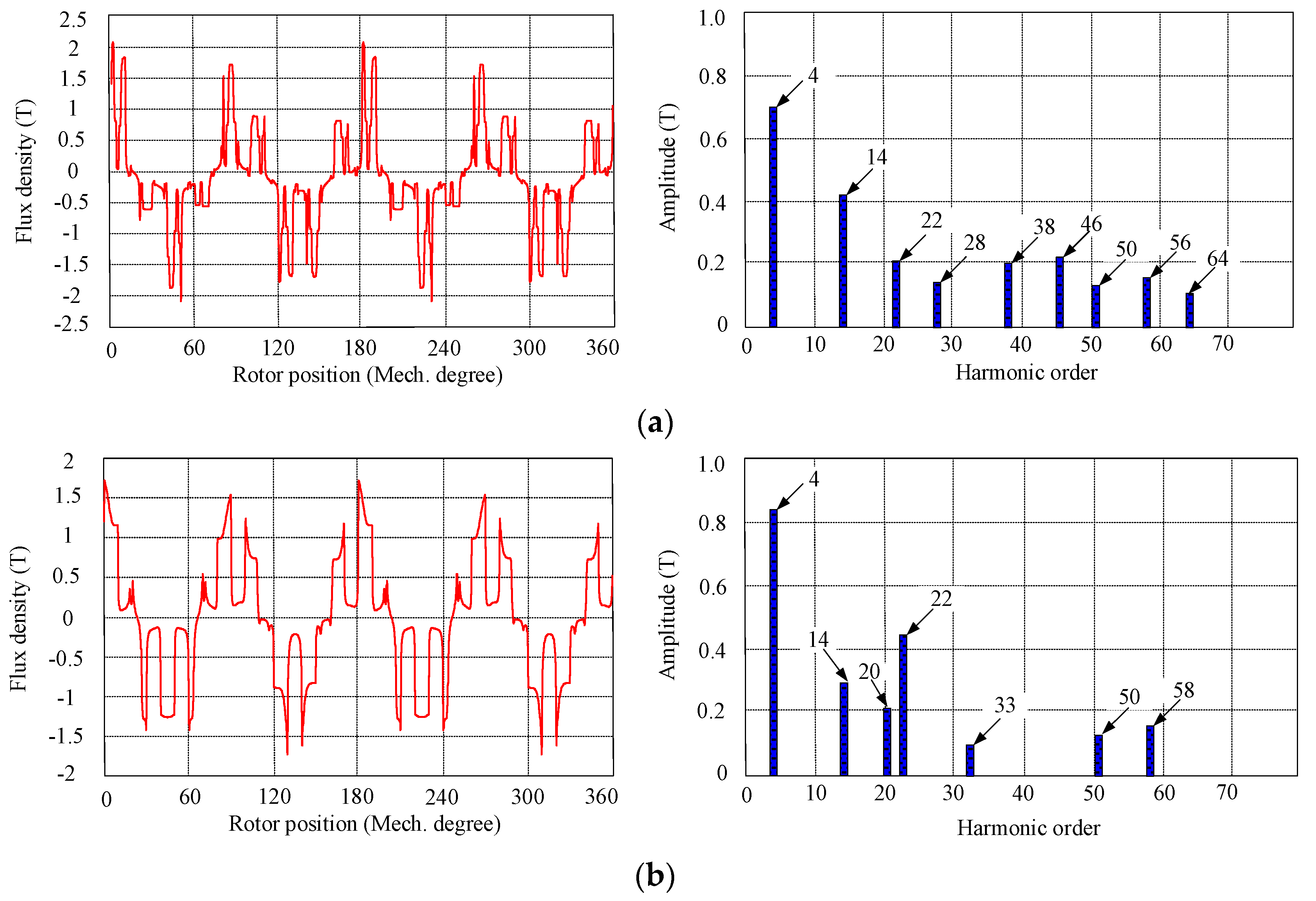
4. Electromagnetic Characteristics Analysis
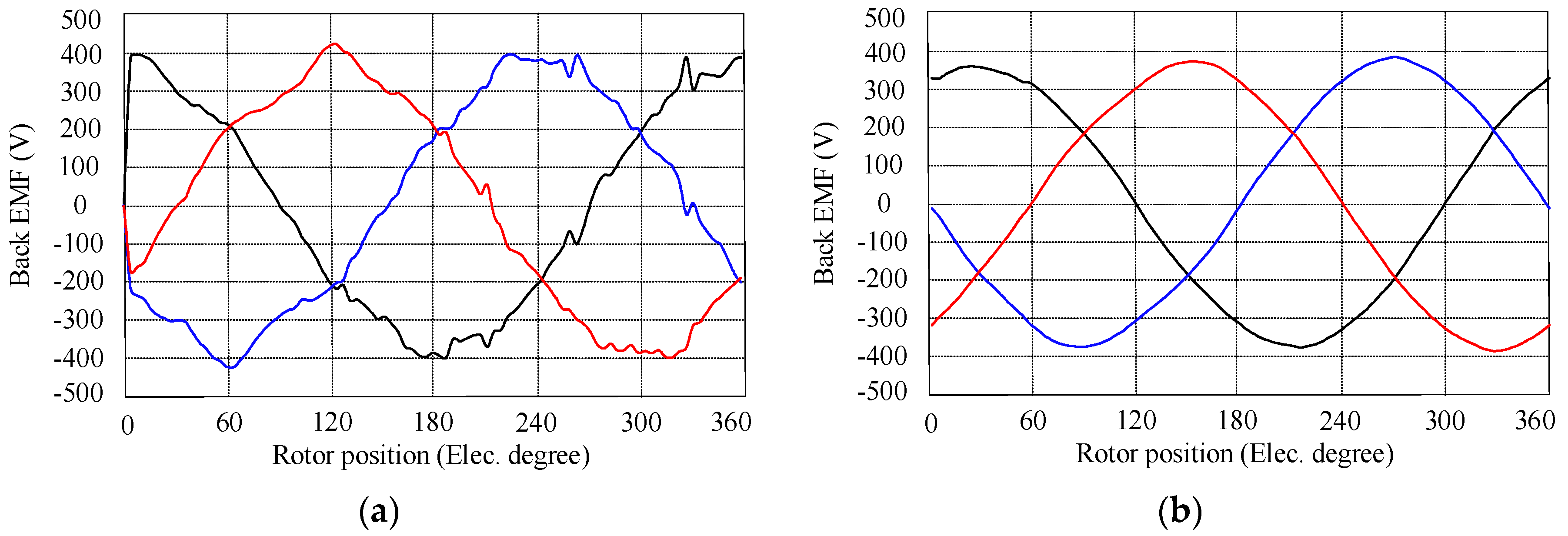
For the purpose of verifying the electromagnetic characteristics of the proposed HTS-FMDS machine, its electromagnetic performance was analyzed by means of 2D-FEA. The key design parameters of the proposed machine are listed in Table 2.

4.1. Back EMF

As a result of the magnetic field modulation by both the modulation-ring rotor and the inner and outer stator teeth, the air-gap magnetic field of the proposed machine contains rich harmonic components. Figure 9 shows the flux-density distribution in the double air-gap and their corresponding harmonic components under no-load condition, whose amplitude is higher than 0.1 T. Among of them, the 4th, 14th, 20th, 22th, 28th, 38th, 46th, 56th, and 64th-order harmonic components are modulated by the modulation-ring rotor, while the 33th, 50th, and 58th-order harmonic components are generated by the modulation of the inner and outer stator teeth.
Since the pole pairs of the armature windings are 14, the harmonic components, which have the same star graph of the slot potential as that of the armature windings with 28 poles, will not cause the distortion of the armature-windings back-EMF, while the other harmonic components will lead to the increase of the total harmonic distortion (THD). Thus, the method of the skewed teeth of modulation-ring rotor is used to eliminate the harmonic components of the air-gap flux-density, so that the sinusoidal back EMF can be obtained. As shown in Figure 10a, the back-EMF waveforms not only have high harmonic components, but also take on an obvious asymmetry of a positive and negative half-wave when the skewed rotor teeth are not applied. On the contrary, by skewing the rotor-teeth with two mechanical degrees, the sinusoidal back EMF can be obtained, as depicted in Figure 10b. Its THD content is less than 2.1%. Figure 11 depicts the variation of the armature-winding inductance with the rotor position. It can be found that the inductance value of the phase winding exhibits obvious fluctuations, because of the modulation of the modulation-ring rotor.

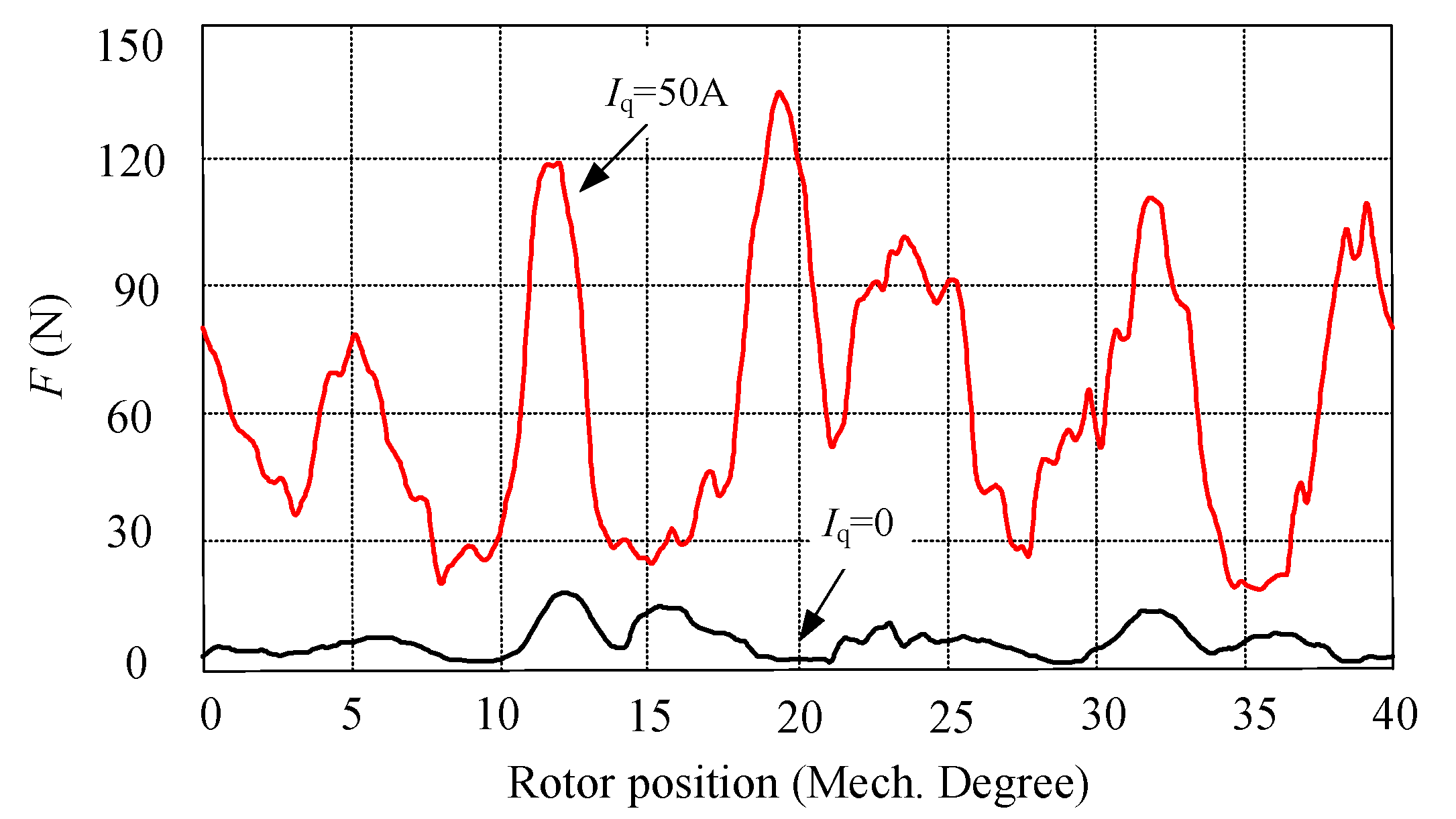
4.2. Unbalanced Magnetic Force

When the proposed HTS machine is in operation, there is a strong radial electromagnetic force, which will cause the mechanical vibration of the machine between the magnetic-ring rotor and the inner and the outer stator cores. Since the proposed machine employs a double stator configuration, its rotor should be designed as a single-end fixed cup-rotor, in order to achieve a mechanical installation. When the cup-rotor suffers from an unbalanced magnetic force (UMF), deformation is liable to occur, resulting in friction between the rotor and stator. In order to eliminate the negative influence of UMF, both the even-number rotor-teeth and stator-teeth were adopted to maintain the symmetry of the magnetic circuit. Furthermore, the numbers of both the stator-teeth and the rotor-teeth have a relatively high common least multiple, which suppresses the generation of UMF by the optimized combination between the poles and slots. In addition, the skewed magnetic-ring rotor further reduces the influence of UMF. Figure 12 depicts the UMF under the conditions of both no load and rated load. It can be found that the amplitude of UMF is only 15 N under no load. However, when the id = 0 control strategy is employed, the amplitude of UMF increases to 135 N under rated load because of the increase of the flux density of both the magnetic-ring rotor and stator cores. Since the proposed machine operates at a low speed, the UMF is within the acceptable range.

4.3. Electromagnetic Torque

In order to investigate the output torque capability of the proposed machine, the variation of the electromagnetic torque with the change of the armature current can be calculated, as described in Figure 13a. It can be found that the output torque increases rapidly with the increase of the armature current, before the armature current reaches the rated value. However, the output torque increases slowly after the armature current is higher than the rated value. Figure 13b shows its steady-state torque waveform when the armature windings were fed with three-phase symmetrical rated current. The rated output torque is 1534 Nm, namely, the torque density of the proposed HTS machine can reach 340 kNm/m3. The torque ripple Tripple was calculated to be only 8.7%, as shown below:
T ripple = T max T min T av
where Tmax, Tmin, and Tav represent the maximum value, minimum value, and average value, respectively, of the electromagnetic torque. This level of torque ripple is acceptable and generally lower than that of other stator-excitation machines [26,27,28]. Also, cogging torque, which results from the interaction between the HTS field-excitation coils in the inner stator and ferromagnetic materials of both the modulation-ring rotor and outer stator, is an important factor that should be taken into consideration when designing the HTS-FMDS machine for low-speed and direct-drive applications. Figure 14 shows the cogging torque of the proposed machine under rated field-excitation currents. It can be found that the magnitude of the cogging torque is only about 4.9% of the average value of the steady torque.

4.4. Efficiency

The efficiency η of the proposed HTS-FMDS machine can be calculated from the following formula:
η = P 2 P 2 + p c u 1 + p f + p F e i n + p F e o u t + p m e c h + p c o o l × 100 %
where P2 is the output mechanical power, pcu1 is the copper loss of armature winding, pf is the excitation loss of HTS coils, pFe-in is the iron loss of inner stator, pFe-out is the iron loss of outer stator, pmech is the mechanical loss, pcool is the cooling loss. According to Equation (5), the efficiency curve of the proposed HTS-FMDS machine under rated speed condition can be obtained, as shown in Figure 15. It can be found that the efficiency of the proposed machine is above 80% when the value of the armature current varies from 10 A to 60 A, namely, the proposed machine possesses the merit of wide high-efficiency operating-area with the variation of load current. It should be noted that the HTS-FMDS machine with low power is non-competitive, since the HTS wires and its cooling consume a relatively high manufacturing cost. However, for the high power machine, the proposed HTS FMDS machine exhibits a clear competitive advantage, because of its advantages of high efficiency and high power density.

5. Conclusions

In this work, an HTS-FMDS machine with a stationary seal for low-speed and direct-drive applications was proposed and investigated. Since the HTS field-excitation windings, which were fed with direct current to offer strong field excitation, were placed in the inner stator, the stationary seal of the cryogenic cooling system can be achieved, hence reducing the manufacturing costs and increasing the operational reliability of the proposed machine. By mounting a ferromagnetic ring on the top of each HTS coil, so as to guide a path for the armature-reaction magnetic field, the quench of the HTS wires, which is resulted by the external magnetic field, can be avoided. The FEA results show that the proposed machine offers the merits of a small UMF, low torque ripple, and high torque density. The proposed HTS-FMDS machine exhibits a potential prospect in marine propulsion and offshore wind power generation.

Author Contributions

Y.W., G.Y., and X.Z. mainly conducted the modeling analysis of the proposed HTS field-modulated double-stator machine and performed the experiments. The manuscript was improved and revised by W.M. and X.L. All of the authors contributed to the paper writing.

Funding

This work was funded in part by the National Natural Science Foundation of China (Projects 51777216 and 51507191), by the Natural Science Foundation of Shandong Province (ZR2018MEE040), by the Application Fundamental Research Funds of Qingdao (Project 17-1-1-28-jch), and by the Fundamental Research Funds for the Central Universities (18CX02114A).

Conflicts of Interest

The authors declare no conflict of interest.

References

  1. Polinder, H.; Ferreira, J.A.; Jensen, B.B.; Abrahamsen, A.B.; Atallah, K.; McMahon, R.A. Trends in wind turbine generator systems. IEEE J. Emerg. Sel. Top. Power Electron. 2013, 1, 174–185. [Google Scholar] [CrossRef]
  2. Yanamoto, T.; Izumi, M.; Yokoyama, M.; Umemoto, K. Electric propulsion motor development for commercial ships in Japan. Proc. IEEE 2015, 103, 2333–2343. [Google Scholar] [CrossRef]
  3. Shafaie, R.; Amirkhanloo, F.; Kalantar, M. Toward an optimum design of large-scale HTS synchronous generator for wind turbine applications. IEEE Trans. Appl. Supercond. 2016, 26, 5201408. [Google Scholar] [CrossRef]
  4. Kalsi, S.S.; Weeber, K.; Takesue, H.; Lewis, C.; Neumueller, H.W.; Blaugher, R.D. Development status of rotating machines employing superconducting field windings. Proc. IEEE 2004, 92, 1688–1704. [Google Scholar] [CrossRef]
  5. Klaus, G.; Wilke, M.; Frauenhofer, J.; Nick, W.; Neumuller, H.W. Design challenges and benefits of HTS synchronous machines. In Proceedings of the 2007 IEEE Power Engineering Society General Meeting, Tampa, FL, USA, 24–28 June 2007. [Google Scholar]
  6. Kalsi, S.S. Development status of superconducting rotating machines. In Proceedings of the 2002 IEEE Power Engineering Society Winter Meeting, New York, NY, USA, 27–31 January 2002. [Google Scholar]
  7. Gamble, B.; Snitchler, G.; Kalsi, S.S. HTS generator topologies. In Proceedings of the 2006 IEEE Power Engineering Society General Meeting, Montreal, QC, Canada, 18–22 June 2006. [Google Scholar]
  8. Cheng, M.; Hua, W.; Zhang, J.; Zhao, W. Overview of stator-permanent magnet brushless machines. IEEE Trans. Ind. Electron. 2011, 58, 5087–5101. [Google Scholar] [CrossRef]
  9. Cheng, M.; Han, P.; Hua, W. General airgap field modulation theory for electrical machines. IEEE Trans. Ind. Electron. 2017, 64, 6063–6074. [Google Scholar] [CrossRef]
  10. Zhu, X.; Xiang, Z.; Zhang, C.; Quan, L.; Du, Y.; Gu, W. Co-reduction of torque ripple for outer rotor flux-switching PM motor using systematic multi-level design and control schemes. IEEE Trans. Ind. Electron. 2017, 64, 1102–1112. [Google Scholar] [CrossRef]
  11. Xiang, Z.; Zhu, X.; Quan, L.; Du, Y.; Zhang, C.; Fan, D. Multilevel design optimization and operation of a brushless double mechanical port flux-switching permanent-magnet motor. IEEE Trans. Ind. Electron. 2016, 63, 6042–6054. [Google Scholar] [CrossRef]
  12. Wang, Y.; Wang, C.; Feng, Q.; Li, X.; Ching, T.W. Fabrication and experiment of racetrack HTS coil for stator field-excitation HTS machine. IEEE Trans. Appl. Supercond. 2017, 27, 5201605. [Google Scholar] [CrossRef]
  13. Wang, Y.; Feng, Q.; Li, X.; Ma, W. Design, analysis, and experimental test of a segmented-rotor high temperature superconducting generator with stationary seal. IEEE Trans. Ind. Electron. 2018. [Google Scholar] [CrossRef]
  14. Wang, Y.; Wang, C.; Feng, Q.; Li, X. Design and experiment of an HTS flux-switching machine with stationary seal. IEEE Trans. Appl. Supercond. 2017, 27, 5201405. [Google Scholar] [CrossRef]
  15. Toba, A.; Lipo, T.A. Generic torque-maximizing design methodology of surface permanent-magnet vernier machine. IEEE Trans. Ind. Appl. 2000, 36, 1539–1546. [Google Scholar] [CrossRef]
  16. Zheng, P.; Song, Z.Y.; Bai, J.G.; Tong, C.D.; Yu, B. Research on an axial magnetic-field-modulated brushless double rotor machine. Energies 2013, 6, 4799–4829. [Google Scholar] [CrossRef]
  17. Li, X.; Chau, K.T.; Cheng, M. Analysis, design and experimental verification of a field-modulated permanent-magnet machine for direct-drive wind turbines. IET Electr. Power Appl. 2015, 9, 150–159. [Google Scholar] [CrossRef]
  18. Wang, Q.; Niu, S. A novel hybrid-excited dual-PM machine with bidirectional flux modulation. IEEE Trans. Energy Convers. 2017, 32, 424–435. [Google Scholar] [CrossRef]
  19. Wang, Q.; Niu, S.; Yang, L. Design optimization and comparative study of novel dual-PM excited machines. IEEE Trans. Ind. Electron. 2017, 64, 9924–9933. [Google Scholar] [CrossRef]
  20. Wu, Z.Z.; Zhu, Z.Q. analysis of air-gap field modulation and magnetic gearing effects in switched flux permanent magnet machines. IEEE Trans. Magn. 2015, 51, 1–12. [Google Scholar] [CrossRef]
  21. Luo, X.; Niu, S.X. Maximum power point tracking sensorless control of an axial-flux permanent magnet vernier wind power generator. Energies 2016, 9, 581. [Google Scholar] [CrossRef]
  22. Du, Y.; Xiao, F.; Hua, W.; Zhu, X.; Cheng, M.; Quan, L.; Chau, K.T. Comparison of flux-switching pm motors with different winding configurations using magnetic gearing principle. IEEE Transa. Magn. 2016, 52, 8201908. [Google Scholar] [CrossRef]
  23. Li, F.; Chau, K.T.; Liu, C. Pole-changing flux-weakening DC-excited dual-memory machines for electric vehicles. IEEE Trans. Energy Convers. 2016, 31, 27–36. [Google Scholar] [CrossRef]
  24. Lee, C.H.T.; Chau, K.T.; Liu, C.; Ching, T.W.; Chen, M. A new magnetless flux-reversal HTS machine for direct-drive application. IEEE Trans. Appl. Supercond. 2015, 25, 5203105. [Google Scholar] [CrossRef]
  25. Lee, C.H.T.; Chau, K.T.; Liu, C.; Qiu, C. Design and analysis of a new multitoothed magnetless doubly-salient machine. IEEE Trans. Appl. Supercond. 2014, 24, 5200804. [Google Scholar] [CrossRef]
  26. Gong, Y.; Chau, K.T.; Jiang, J.Z.; Yu, C.; Li, W. Design of doubly salient permanent magnet motors with minimum torque ripple. IEEE Trans. Magn. 2009, 45, 4704–4707. [Google Scholar] [CrossRef] [Green Version]
  27. Lee, C.H.T.; Chau, K.T.; Liu, C.; Ching, T.W.; Li, F. Mechanical offset for torque ripple reduction for magnetless double-stator doubly salient machine. IEEE Trans. Magn. 2014, 50, 1–4. [Google Scholar] [CrossRef]
  28. Chau, K.T. Electric Vehicle Machines and Drives—Design, Analysis and Application; Wiley-IEEE Press: Hoboken, NJ, USA, 2015. [Google Scholar]
Figure 1. Configurations of the proposed high temperature superconducting (HTS) field-modulation double-stator (HTS-FMDS) machine: (a) cross-section and three-dimensional model and (b) HTS coil and its Dewar.
Energies 11 01269 g001aEnergies 11 01269 g001b
Figure 2. Magnetic-flux path of the proposed machine: (a) field-excitation magnetic-field and (b) armature-reaction magnetic-field.
Energies 11 01269 g002
Figure 3. Operating principle.
Energies 11 01269 g003
Figure 4. Ferromagnetic ring parameters.
Energies 11 01269 g004
Figure 5. Magnetic flux density contour plot: (a) rated load without field-excitation current and (b) rated load with rated field-excitation current.
Energies 11 01269 g005
Figure 6. Magnetic flux density of point A, B, and C without field-excitation current: (a) magnetic flux density and (b) harmonic analysis.
Energies 11 01269 g006
Figure 7. Magnetic flux density of point A, B, and C with rated field-excitation current: (a) magnetic flux density and (b) harmonic analysis.
Energies 11 01269 g007
Figure 8. Anisotropy of critical current in applied magnetic field at 77 K with different α.
Energies 11 01269 g008
Figure 9. Distribution of air-gap flux-density and their harmonic components: (a) outer air-gap and (b) inner air-gap.
Energies 11 01269 g009
Figure 10. Back electromagnetic force (EMF): (a) without skew and (b) with skew.
Energies 11 01269 g010
Figure 11. Variation of armature-winding inductance.
Energies 11 01269 g011
Figure 12. Unbalanced magnetic force (Iq is the quadrature component of the armature current).
Energies 11 01269 g012
Figure 13. Electromagnetic torque (TN is the rated torque): (a) electromagnetic torque variation with armature current and (b) rated electromagnetic torque.
Energies 11 01269 g013
Figure 14. Cogging torque under rated field-excitation currents.
Energies 11 01269 g014
Figure 15. Variation of efficiency with armature current under rated speed condition.
Energies 11 01269 g015
Table 1. Key parameters of the high temperature superconducting (HTS) wire.
ParametersValue
Ic @ 77 K, 0 T120 A
Max. tensile strength100 MPa @ 77 K
Critical bending radius30 mm
Thickness0.25 mm
Width4.2 mm
Table 2. Key parameters of the proposed machine.
ParametersValue
Number of outer stator teeth42
Number of inner stator teeth8
Number of pole pairs of armature windings14
Number of pole pairs of field-excitation windings4
Number of modulation-ring rotor teeth18
Stator outside diameter of outer stator (mm)760
Stator inside diameter of outer stator (mm)546.4
Stator outside diameter of inner stator (mm)504
Stator inside diameter of inner stator (mm)240
Rotor outside diameter (mm)42
Stack length (mm)100
Inner air-gap length (mm)0.6
Outer air-gap length (mm)0.6
Number of phases3
Rated speed (rpm)167
Rated power (kW)25
HTS materialBi-2223
Number of turns of each HTS winding (turn)80
Consumption of total HTS wires (m)373

