SnSb Alloy Blended with Hard Carbon as Anode for Na-Ion Batteries

1
Department of Chemical Engineering, Interdisciplinary Graduate School of Engineering Sciences, Kyushu University, Fukuoka 816-8580, Japan
2
International Institute for Carbon-Neutral Energy Research, Kyushu University, Fukuoka 819-0395, Japan
3
Institute for Materials Chemistry and Engineering, Kyushu University, Fukuoka 816-8580, Japan
4
International Training Institute for Materials Science, Hanoi University of Science and Technology, No. 1 Dai Co Viet, Hanoi 100000, Vietnam
*
Author to whom correspondence should be addressed.
Energies 2018, 11(6), 1614; https://doi.org/10.3390/en11061614
Submission received: 15 May 2018
/
Revised: 9 June 2018
/
Accepted: 15 June 2018
/
Published: 20 June 2018
(This article belongs to the Special Issue Electrochemical Energy Conversion and Storage Technologies 2018)
Abstract
:SnSb binary alloys blended with reduced graphene oxide (SnSb/RGO) or mixtures of SnSb/RGO with hard carbon (SnSb/RGO+HC) were tested as anode materials for sodium-ion batteries. The presence of hard carbon in the SnSb/RGO+HC blend improves its cycle efficiency and rate performance substantially. The synergy between the SnSb/RGO and the hard carbon phase is explained by the buffer action of the hard carbon, preventing SnSb interparticle agglomeration during the repeated recharge cycles. The feasibility of SnSb alloy anode for sodium-ion batteries was confirmed in full cell configuration vs. Na3V2(PO4)2F3 cathode.
1. Introduction
Recent lithium-ion battery designs have great advantages such as their high energy density, low retention, low self-discharge and long cycle life; however, their cost and resource restrictions are not suitable for large scale applications. This is why a great deal of effort has recently been devoted to the development of lower cost, environmentally benign electrode active materials with performance close to that of lithium-ion batteries. Na-ion batteries appear to be the most suitable candidate, they could potentially show similar characteristics to Li-ion batteries, with lesser price and resource restrictions.
Historically, the main obstacle for the development of the viable sodium-ion battery was the absence of a suitable anode host for Na+ [1]. Graphite, which is the common lithium-ion battery anode, cannot be used for their sodium-ion counterparts because Na+ could intercalate only in hard carbons. However, even such hard carbon shows less capacity and higher voltage hysteresis. On the other hand, developing high capacity alloying type anodes for sodium-ion batteries could not only boost their energy density, but may also improve their safety because NaxM alloys have slightly higher thermodynamic potential than that of the counterparts of LixM alloys. However, Na alloys electrochemically have fewer elements than Li. For example, Si and Al alloy readily with Li but are inactive towards Na. Practically, alloy elements usable as anodes of Na ion batteries are limited to Sn [2,3], Sb [4,5], P [6,7], and Ge [8,9]. These studies have clearly pointed out that the reaction pathway between the above elements and Na is not straightforwardly related to its performance against Li. Often different reaction mechanisms take place. While Li tends to form alloys LixM with predefined stoichiometry that correspond to the Li-M phase diagrams, Na forms amorphous intermediate phases NaxM and only the fully sodiated or fully desodiated states tend to form well-defined crystalline phases. This behavior is explained by the larger atomic radius of Na, which makes formation of well-defined intermediate crystalline phases kinetically unfavorable.
As a rule of thumb, binary alloy anodes show better electrochemical performance than those consisting of a single Li or Na-alloying element. For example, Xiao et al. reported a SnSb/C nanocomposite and compared it to Sn/C and Sb/C nanocomposites all prepared by means of high energy mechanical milling [10]. The SnSb/C nanocomposite showed 544 mAh·g−1 Na storage capacity and demonstrated better cyclability than the Sn/C and Sb/C nanocomposites. Qian et al. prepared a Sn4P3/C nanocomposite also by means of high energy mechanical milling [11]. It delivered a high reversible capacity of 850 mAh·g−1 at 50 mA·g−1 and 86% capacity retention over 150 cycles. Recently, many other binary phosphide anodes such as InP and CuP2 have also been proposed by Sakaguchi et al. [12]. Improved cycling performance of the binary alloys M1M2 against Li or Na is attributed to the sequential alloying of the elements composing the binary alloy at slightly different potentials. Sequential alloying allows formation of Na-rich phase NaxM1 of the element M1 which alloys at higher potential with Na, intimately dispersed within a conducting buffer matrix of the second element M2, alloying at a lower potential. Such a sequential alloying could prevent particle aggregation (electrochemical sintering), which could occur in cases when a single alloying element is cycled vs. Na/Na+. The aforementioned works [10,11,12] have already demonstrated that the binary alloys are promising anode candidates, but the active materials were prepared using high energy ball-milling, which is not suitable for high-scale manufacturing. In addition, compositions prepared by means of high energy ball-milling have an extremely large specific surface area and it is difficult to implement them in practical electrodes. To the contrary, Darwiche et al. have demonstrated micrometric size SnSb alloy prepared by a facile short time (1 h) ball-milling, which shows outstanding cycle performance of more than 160 cycles without notable capacity fading [13]. However, the coulomb efficiency in this case could not exceed 97%, which would cause fast failure in full cell configuration.
Thus, in this study, to improve the anode performances of binary alloys, we investigated the possibility of mixed anodes of SnSb and the oxides with carbonaceous materials synthesized by various synthesis methods, because porous and conductive carbonaceous material as the third component should be effective in releasing the large volume change during cycling and reducing the charge/discharge overpotential. At first, SnO/Sb2O3 was synthesized hydrothermally in the presence of graphene oxide (GO). The oxides were then transformed into SnSb alloy with the appropriate morphology by gas phase (Ar + 5% H2) reduction.
2. Experimental
At first graphene oxide (GO) was synthesized by the modified Hummers method [14,15,16]. Four grams of graphite was dispersed in 92 mL conc. H2SO4. The suspension was cooled in an ice bath to 0 °C and 2 g NaNO3 was added under continuous stirring at such a rate that the suspension was kept at 0 °C. Twelve grams of KMnO4 was added slowly and the mixture was allowed to reach room temperature. The reaction mixture was stirred overnight at room temperature. Then 180 mL of distilled water was added under continuous stirring which raised the temperature of the mixture to 60 °C. Fifteen minutes later the reaction was terminated by the addition of 20 mL 30% H2O2 diluted in 560 mL distilled water. The dry residue was filtered, triple-washed with distilled water and dried at 80 °C.
0.18 g of the as prepared GO sample was dispersed in 100 mL distilled water containing 5 g trisodium citrate (C6H5O7Na3·2H2O) by sonication (GO concentration 1.5 mg mL−1). Then, 0.25 g SnCl2·H2O (0.011 M) and 0.254 g SbCl3 (0.011 M) were added to the GO dispersion and the solution was adjusted to pH 9 with aqueous ammonia. The solution was further sonicated for 30 min. It was then transferred to hermetically sealed Teflon flasks and treated at 150 °C for 1 h by microwave-assisted heating. Trisodium citrate acts as a buffer during the hydrothermal treatment, which allows complete precipitation of SnCl2 and SbCl3 as the respective oxides. After completion of the hydrothermal reaction, the dry residue containing a mixture of SnO2 and Sb2O3 intimately mixed with GO was filtered and treated at 800 °C for 3 h under Ar + 5% H2 gas to reduce SnO2, Sb2O3, GO and obtain a sample further denoted as SnSb/RGO (93% SnSb + 7% RGO), where RGO stands for reduced graphene oxide. Part of the SnSb/RGO sample was tested as prepared as anode material vs. Na/Na+ and another part of it was mixed with hard carbon (Carbotron P(J); Kureha Corp., Tokyo, Japan) by mild mechanical milling at 400 rpm for 1 h, which yielded a sample further denoted as SnSb/RGO+HC. The nominal weight ratio of SnSb/RGO to hard carbon was set to 9:1 and the amounts of the ingredients in SnSb/RGO+HC is 83.7% SnSb, 6.3% RGO, and 10% HC.
Samples were analyzed by X-ray diffraction with a 15 kW high-brilliance Cu-Kα rotating disk anode (XRD; Rigaku TTRIII, Tokyo, Japan). Particle size and particle morphology were observed by transmission electron microscope (TEM; JEOL JEM2100F, Tokyo, Japan).
Working electrodes were prepared by mixing appropriate amounts of the active material/acetylene black (AB) mixture with 2 wt % of a DI water-alcohol mixture (4:1 by weight) of polyacrylic acid (PAA) (MW = 1,250,000) and carboxymethyl cellulose (CMC) (MW = 700,000; Sigma-Aldrich, St. Louis, MI, USA) (PAA:CMC = 1:1 by weight). The ingredients were added to a 10 mL polypropylene vial containing 3 g of zirconia balls (φ3 mm). The vials were then placed in a rocking mill (Seiwa Giken Co., Ltd., Osaka, Japan) and mixed for 60 min at 50 Hz to form slurry. The slurry was coated onto a 20 µm Cu foil current collector by the doctor blade technique and dried in a vacuum oven at 80 °C overnight. Composition of the anodes was 70 wt % active material, 20 wt % AB and 10 wt % binder (PAA + CMC = 1:1).
Electrochemical tests were carried out in two-electrode 2032 coin cells (Hohsen Corp., Tokyo, Japan). Sodium metal foil was used as a counter electrode. The working and counter electrode were both punched as 15 mmφ disks. The loading density of the active material in the anode was 2.0 (±0.05) mg. 1 M NaPF6 dissolved in ethylene carbonate (EC) and diethylene carbonate (DEC) 1:1 by volume (Tomiyama Pure Chemical Industries, Ltd., Tokyo, Japan) was used as an electrolyte. The separator was a GF/A glass fiber filter paper (Whatman, Boston, MA, USA). Cycle life and rate performance were tested under different current densities in the voltage range of 1.5–0.01 V. The cathodes used for full-cell measurements were prepared in a similar manner. The cathode active material Na3V2(PO4)2F3 was mixed with AB and polyvinylidene difluoride (PVDF) to form a slurry (70:25:5 by weight), which was coated onto a 20 µm Al foil current collector. The voltage range of the full cells was set between 3.9 V–1.4 V and the current density of the full cells was 0.2 mA cm−2 (ca. 100 mA·g−1 for the anode). Anode (SnSb/RGO+HC): Cathode (Na3V2(PO4)3F3) weight ratio was fixed to 1:5. Taking into account that first charging capacity of Na3V2(PO4)3F3 is 145 mAh·g−1 and that for SnSb/RGO+HC 650 mAh·g−1, a full cell test was performed with anode-limited cells.
3. Results and Discussion
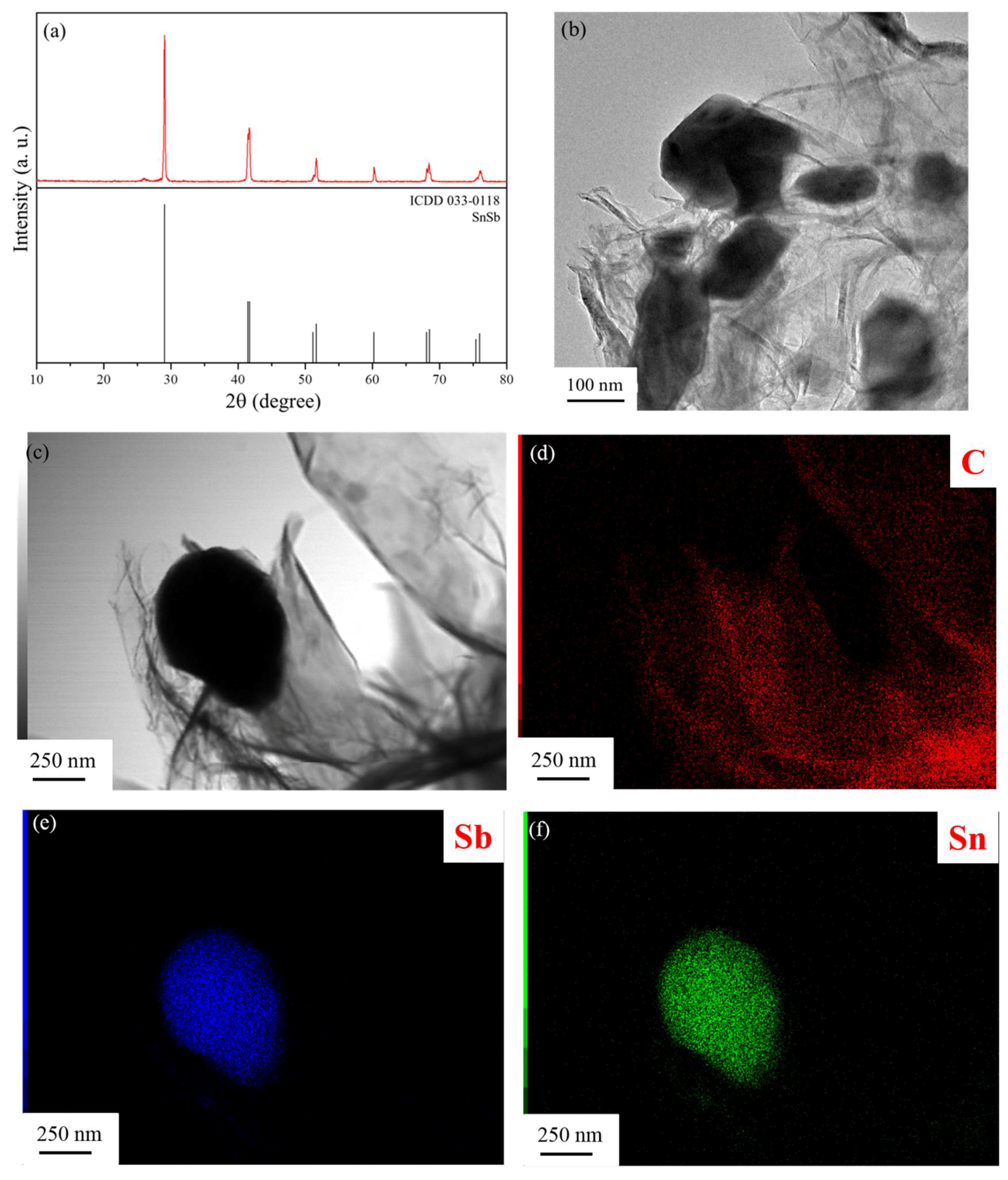
XRD pattern of the as prepared SnSb/RGO+HC sample is shown in Figure 1a. All diffraction peaks belong to the SnSb alloy (ICDD 033-0118) showing that our experimental procedure yielded pure single phase SnSb. As expected, RGO is invisible for the X-rays because of its small amount and thickness of several atomic layers, which cannot give a detectable diffraction pattern and it is completely outshined by SnSb. Only a dim broad peak due to the hard carbon appears at ca. 27° 2θ-angle. The TEM image shown in Figure 1b reveals that SnSb particles have random shape and particle size distribution 100–500 nm possibly because during the hydrothermal process RGO acts as crystallization centers and prevents further sintering of the tin and antimony oxides into large clusters. Notably, GO also prevents particle agglomeration during the reduction under Ar + 5% H2 atmosphere at 800 °C. EDS mapping (Figure 1d–f) further confirms that the Sn and Sb are uniformly distributed within the SnSb particles, which are coated by graphene layers.
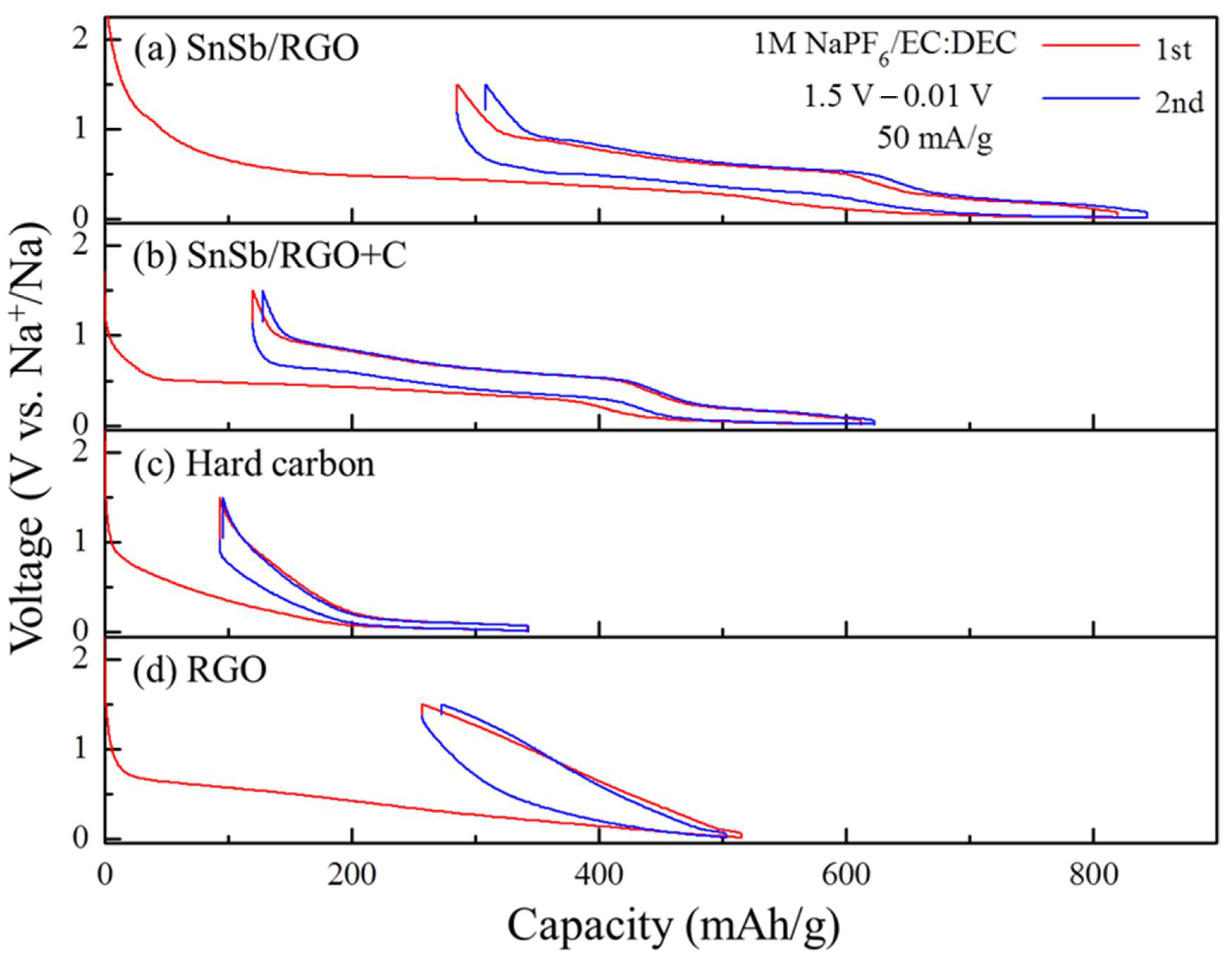
Figure 2 shows the voltage profiles of the first two cycles for the SnSb/GO+HC composite and its ingredients at a relatively low current density of 50 mA·g−1. The reversible capacities of the first cycle for SnSb/RGO, SnSb/RGO+HC, hard carbon and RGO are 534, 502, 248, and 259 mAh·g−1 with coulombic efficiencies of 65.2%, 77.2%, 72.8%, and 50.2%, respectively. As expected, SnSb/RGO delivers higher capacity due to the higher amount of the high capacity SnSb alloy, but SnSb/GO+HC blend shows superior reversibility. Clearly, composite ingredients are active towards Na, Sn, Sb, GO and HC and all react with Na. When considering the high-capacity ingredient SnSb, the first element to alloy with Na+ is expected to be Sb, followed by Sn:
SnSb + 3Na+ + 3e− ↔ Na3Sb + Sn/334 mAh·g−1
Na3Sb + Sn + 3.75Na+ + 3.75 e− ↔ Na3Sb + Na3.75Sn/752 mAh·g−1
In case both Sb and Sn form Na alloys with maximal sodium uptake, the theoretical capacity should be 752 mAh·g−1. If we assume that in the studied voltage window both RGO and HC are fully sodiated, the total capacity of these composites is expressed as:
Capacitytotal = SnSb(%) × SnSb(Cap) + RGO(%) × RGO(Cap) + HC(%) × HC(Cap)
Equation (3) allows us to define the term utilization of the SnSb alloy as the ratio between the observed and theoretically predicted capacity of the composite electrode.
Data shown in Figure 2 is summarized in Table 1. The second column shows the experimental capacity, which corresponds to the reversible capacity over the first cycle. It is assumed that both RGO and hard carbon show their full sodiation capacity, i.e., 259 and 248 mAh·g−1. Total capacity of the composite in Equation (3) was solved with respect to the SnSb alloy. Since the intermediate phases NaxSb and NaxSn are amorphous and could not be detected by conventional XRD technique, the total capacity is formally calculated as the mole fraction of Na reacted with SnSb, calculated by Equation (4):
where x is the mole fraction of Na in NaxSnSb, 6.75 is the theoretically maximal amount of Na that can be alloyed with SnSb if we suppose that the final composition is Na3Sb + Na3.75Sn, and 752 mAh·g−1 is the maximal capacity if both Sn and Sb form alloys with maximal Na uptake. Cap (remaining) is found by the solution of Equation (3) with respect to SnSb alloy.
x = 6.75 × Cap(remaining)/752
Table 1 reveals that SnSb/RGO and SnSb/RGO+HC show almost the same utilization of the SnSb alloy. Therefore, the presence of hard carbon does not change sodium uptake of the SnSb alloy.
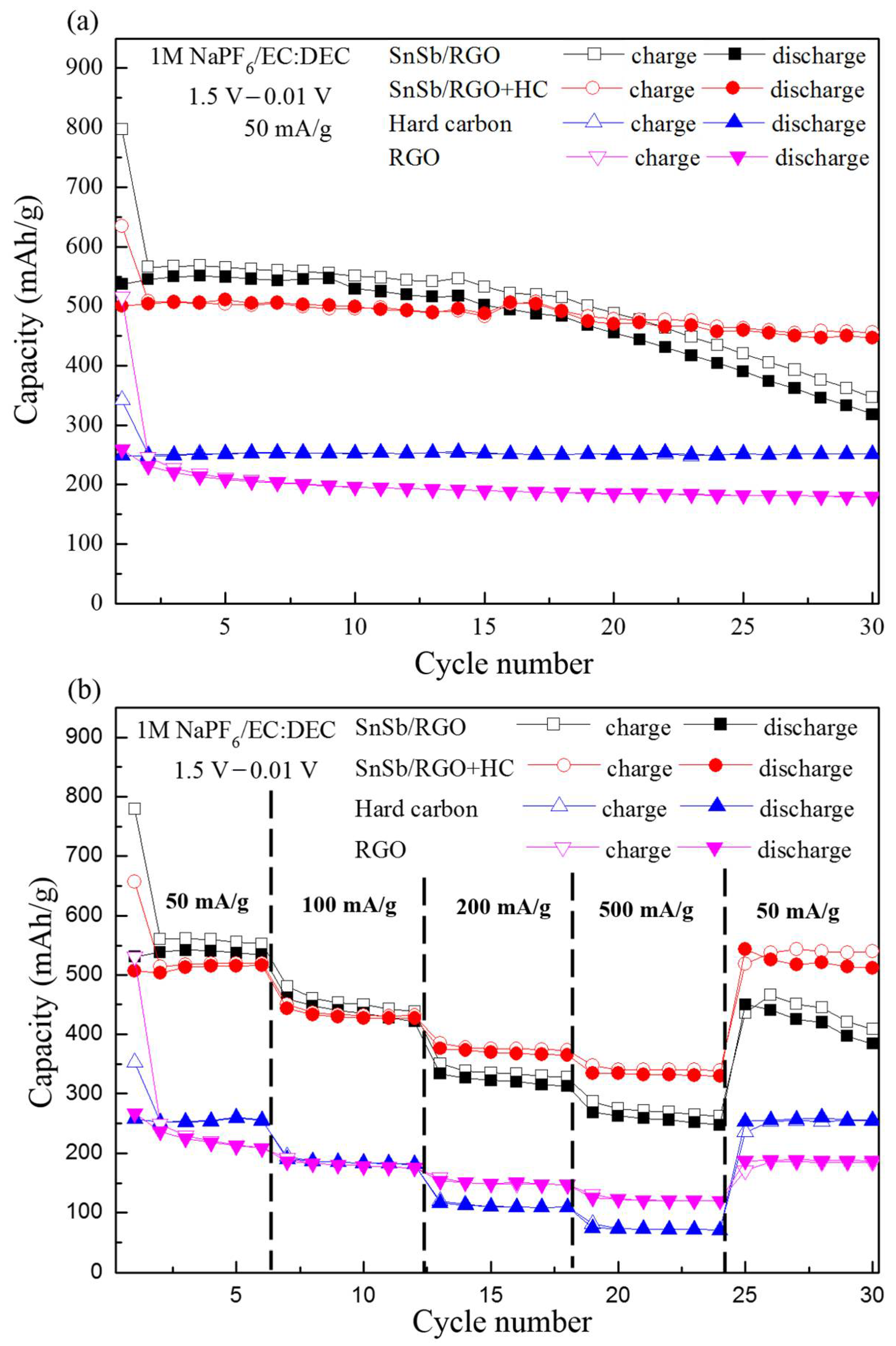
Figure 3a,b further compares the cycling and rate performances of the SnSb/RGO+HC composite and its ingredients. SnSb/RGO and SnSb/RGO+HC exhibit almost the same capacity at moderate current densities 50 and 100 mA·g−1. However, at 200 and 500 mA·g−1, SnSb/RGO shows worse rate capability than SnSb/RGO+HC. In addition, when the current density is reset to 50 mA·g−1, SnSb/RGO+HC capacity at the 30th cycle is almost identical to the capacity at the 3rd cycle. In contrast, SnSb/RGO shows only ca. 70% capacity at the 30th cycle compared with the 3rd cycle.
Figure 4 shows the coulomb efficiencies of SnSb/RGO, SnSb/RGO+C and hard carbon over the initial 15 cycles. The coulomb efficiencies of SnSb/RGO at the 2nd and 5th cycle are 95.9%, and 97.7% and there is clear degradation after the 10th cycle. Surprisingly, SnSb/RGO+HC shows efficiency, comparable to the pure hard carbon, exceeding 99(+)% after the initial cycle and good efficiency retention.
The synergy between the SnSb/RGO and the hard carbon could be rationalized. The irreversible capacity of SnSb/RGO from the 2nd to the 5th cycle should be attributed to subsequent electrochemical grinding (during Na alloying) and sintering (Na dealloying) with the SnSb alloy. In the absence of hard carbon these subsequent reconstitutions might cause a gradual merger of the SnSb particles, which become Sn-rich around 0.5 V vs. Na/Na+ where most of the Sb is transformed into Na3Sb. Larger particle size would result in electrode cracking and worse rate performance. In addition, electrode cracking exposes the fresh electrode area where the new SEI layer grows and thus reduces the coulomb efficiency. This consumes extra Na+ and would cause failure in full cell configuration.
These data reveal that even small, 10 wt % addition of hard carbon to the SnSb/RGO blend does not change sodium uptake of the SnSb alloy, but simultaneously improves the coulomb efficiency, the rate capability and the cycle performance of the composite anode. Further and deeper study is necessary to observe in situ the above proposed mechanism which cannot be monitored by simply observing XRD patterns at various states of charge. To confirm the feasibility of SnSb/RGO+HC in full cells, SnSb/RGO+C was paired with Na3V2(PO4)2F3 (NVPF) [17].
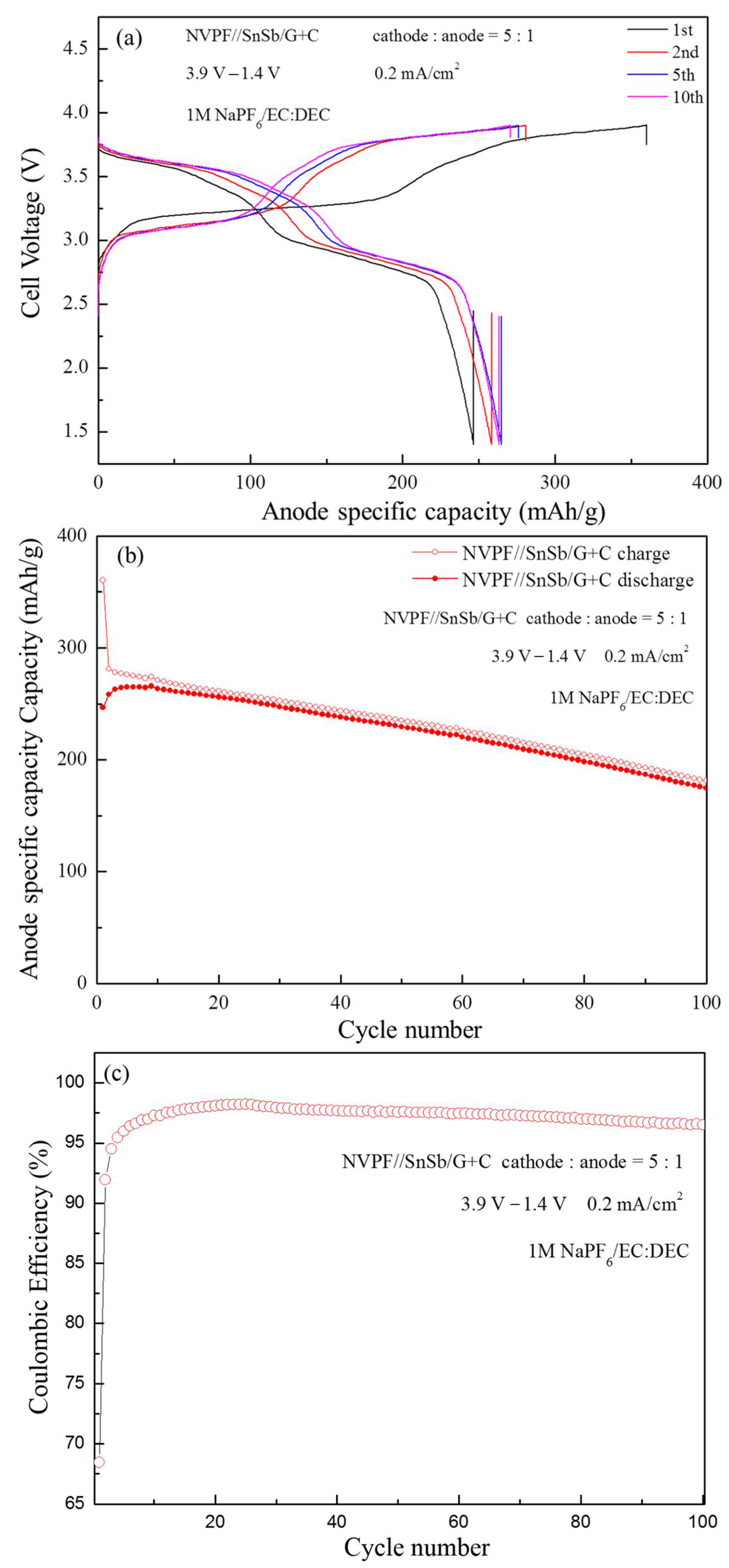
The voltage profiles of several selected cycles and the cycling performance of the full cells are shown in Figure 5. Even without thorough optimization, the NVPF//SnSb/RGO+HC cell shows reasonable cycling performance over 100 cycles (Figure 5b). The initial anode specific capacity in the NVPF//SnSb/RGO+C cell was 360/246 mAh·g−1 (charge/discharge), with coulombic efficiency of 68.47%. Notably, the NVPF//SnSb/RGO+C cell exhibits ~3.2 V cell voltage. The capacity retention after 100 cycles is about 70%.
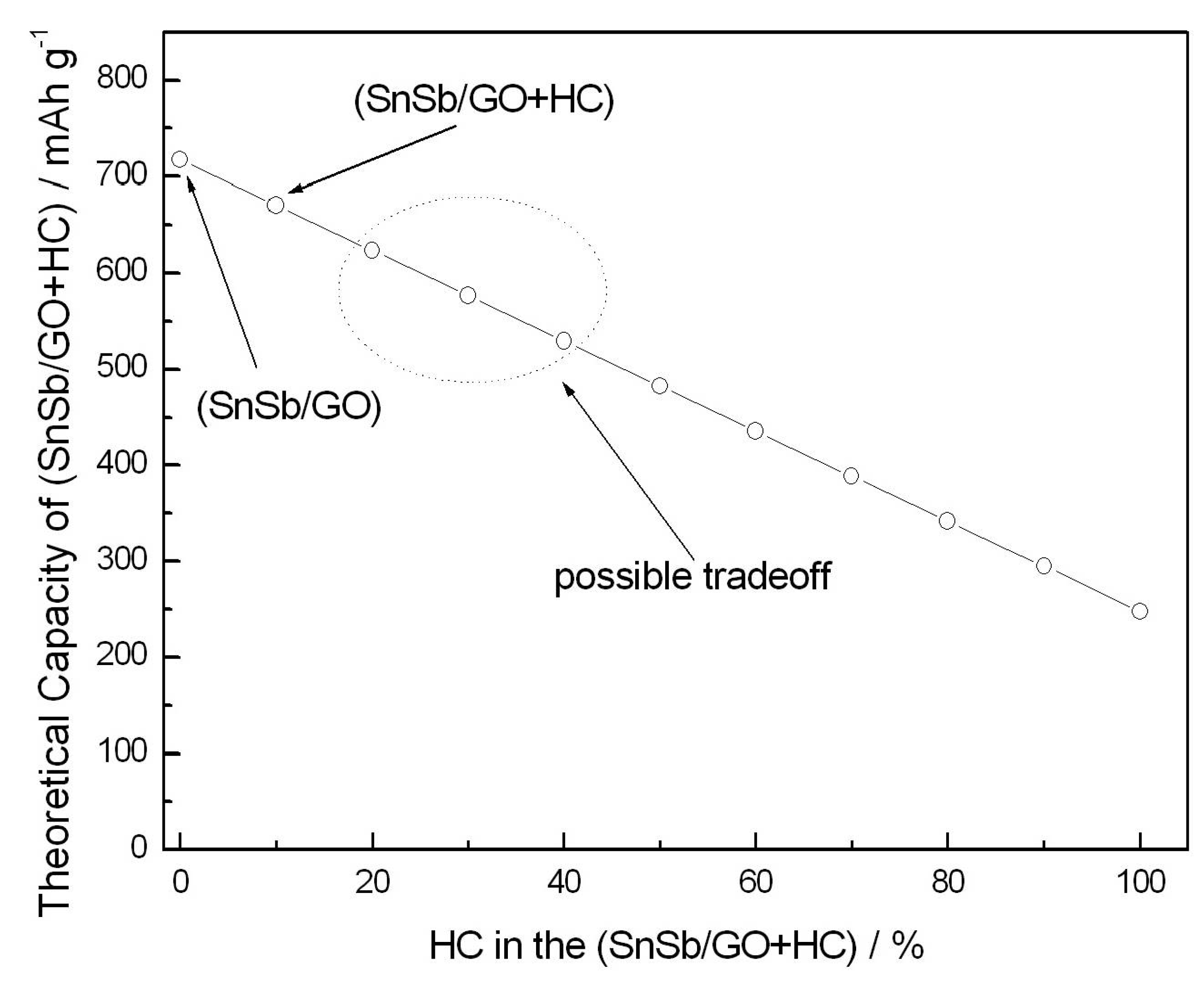
Further improvement of the reversibility and coulomb efficiency should be possible at the expense of somewhat reduced capacity. Figure 6 shows estimation of the (SnSb/GO+HC) composite capacity as a function of the HC content. The estimation is performed in accordance with Equation (3) showing linear decrease of the overall capacity with HC content. Compositions with higher amount of hard carbon and possibly another binder formulation are likely to show efficiency and cycle performance matching the requirements of practical sodium-ion batteries, which will be a topic of further investigations.
4. Conclusions
In this study, SnSb alloy blended with two types of carbon, graphene oxide (GO) and hard carbon (HC), which was prepared by a combination of hydrothermal, gas phase reduction, and mild mechanical milling processes. Both carbonaceous phases have a specific function. Graphene oxide sheets were used as crystallization centers during the hydrothermal treatment of the aqueous SnCl2 and SbCl3. GO also prevented particle agglomeration during the reduction step under Ar + 5%H2. However, GO alone is not sufficient to improve the cycle life and coulomb efficiency.
On the other hand, even without thorough optimization, the SnSb/GO+HC composite demonstrates reasonable cycle life, higher rate capability, and coulomb efficiency comparable to the pure hard carbon. In the full-cell test, NVPF//SnSb/RGO+HC exhibited high cell voltage of ~3.2 V and reasonable cycle performance over the first 100 cycles. Further improvement of SnSb-electrode for sodium-ion batteries should be possible with higher amount of HC, optimized binder formulation and electrolyte additives.
Author Contributions
S.O., N.D., and Y.C.L. conceived and designed the experiments; Y.C.L. performed the experiments; N.D., S.O. and T.H.B. analyzed the data; S.O. and T.H.B. contributed reagents/materials/analysis tools; Y.C.L., N.D. and S.O. wrote the paper; S.O. has supervised the work.
Funding
This research received no external funding.
Acknowledgments
This work was financially supported by the Elements Science & Technology Projects of MEXT, Japan.
Conflicts of Interest
The authors declare no conflicts of interest.
References
- Kim, S.W.; Seo, D.H.; Ma, X.; Ceder, G.; Kang, K. Electrode Materials for Rechargeable Sodium-Ion Batteries: Potential Alternatives to Current Lithium-Ion Batteries. Adv. Energy Mater. 2012, 2, 710–721. [Google Scholar] [CrossRef]
- Komaba, S.; Matsuura, Y.; Ishikawa, T.; Yabuuchi, N.; Murata, W.; Kuze, S. Redox Reaction of Sn-polyacrylate Electrodes in Aprotic Na Cell. Electrochem. Commun. 2012, 21, 65–68. [Google Scholar] [CrossRef]
- Zhu, H.; Jia, Z.; Chen, Y.; Weadock, N.; Wan, J.; Vaaland, O.; Han, X.; Li, T.; Hu, L. Tin Anode for Sodium-ion Batteries Using Natural Wood Fiber as a Mechanical Buffer and Electrolyte Reservoir. Nano Lett. 2013, 13, 3093–3100. [Google Scholar] [CrossRef] [PubMed]
- Darwiche, A.; Marino, C.; Sougrati, M.T.; Fraisse, B.; Stievano, L.; Monconduit, L. Better Cycling Performances of Bulk Sb in Na-Ion Batteries Compared to Li-Ion Systems: An Unexpected Electrochemical Mechanism. J. Am. Chem. Soc. 2012, 134, 20805–20811. [Google Scholar] [CrossRef] [PubMed]
- Qian, J.; Chen, Y.; Wu, L.; Cao, Y.; Ai, X.; Yang, H. High capacity Na-storage and superior cyclability of nanocomposite Sb/C anode for Na-ion batteries. Chem. Commun. 2012, 48, 7070–7072. [Google Scholar] [CrossRef] [PubMed]
- Qian, J.; Wu, X.; Cao, Y.; Ai, X.; Yang, H. High Capacity and Rate Capability of Amorphous Phosphorus for Sodium Ion Batteries. Angew. Chem. Int. Ed. 2013, 52, 4633–4636. [Google Scholar] [CrossRef] [PubMed]
- Kim, Y.; Park, Y.; Choi, A.; Choi, N.; Kim, J.; Lee, J.; Ryu, J.H.; Oh, S.M.; Lee, K.T. Amorphous Red Phosphorus/carbon Composite as a Promising Anode Material for Sodium Ion Batteries. Adv. Mater. 2013, 25, 3045–3049. [Google Scholar] [CrossRef] [PubMed]
- Baggetto, L.; Keum, J.K.; Browning, J.F.; Veith, G.M. Germanium as Negative Electrode Material for Sodium-ion Batteries. Electrochem. Commun. 2013, 34, 41–44. [Google Scholar] [CrossRef]
- Abel, P.R.; Lin, Y.M.; Souza, T.; Chou, C.Y.; Gupta, A.; Goodenough, J.B.; Hwang, G.S.; Heller, A.; Mullins, C.B. Nanocolumnar Germanium Thin Films as a High-Rate Sodium-Ion Battery Anode Material. J. Phys. Chem. C 2013, 117, 18885–18890. [Google Scholar] [CrossRef]
- Xiao, L.; Cao, Y.; Xiao, J.; Wang, W.; Kovarik, L.; Niea, Z.; Liu, J. High Capacity, Reversible Alloying Reactions in SnSb/C Nanocomposites for Na-ion Battery Applications. Chem. Commun. 2012, 48, 3321–3323. [Google Scholar] [CrossRef] [PubMed]
- Qian, J.; Xiong, Y.; Cao, Y.; Ai, X.; Yang, H. Synergistic Na-storage Reactions in Sn4P3 as a High-capacity, Cycle-stable Anode of Na-ion Batteries. Nano Lett. 2014, 14, 1865–1869. [Google Scholar] [CrossRef] [PubMed]
- Usui, H.; Domi, Y.; Yamagami, R.; Fujiwara, K.; Nishhida, H.; Sakaguchi, H. Sodiation–Desodiation Reactions of Various Binary Phosphides as Novel Anode Materials of Na-Ion Battery. ACS Appl. Energy Mater. 2018, 1, 306–311. [Google Scholar] [CrossRef]
- Darwiche, A.; Sougrati, M.T.; Fraisse, B.; Stievano, L.; Monconduit, L. Facile Synthesis and Long Cycle Life of SnSb as Negative Electrode Material for Na-ion Batteries. Electrochem. Commun. 2013, 32, 18–21. [Google Scholar] [CrossRef]
- Peled, E. The Electrochemical Behavior of Alkali and Alkaline Earth Metals in Nonaqueous Battery Systems—The Solid Electrolyte Interphase Model. J. Electrochem. Soc. 1979, 126, 2047–2051. [Google Scholar] [CrossRef]
- Hummers, W.S.; Offeman, R.E. Preparation of Graphitic Oxide. J. Am. Chem. Soc. 1958, 80, 1339. [Google Scholar] [CrossRef]
- Zaaba, N.I.; Foo, K.L.; Hashim, U.; Tan, S.J.; Liu, W.-W.; Voon, C. Synthesis of Graphene Oxide using Modified Humers Methhod: Solvent Influence. Procedia Eng. 2017, 184, 469–477. [Google Scholar] [CrossRef]
- Chihara, K.; Kitajou, A.; Gocheva, I.D.; Okada, S.; Yamaki, J. Cathode Properties of Na3M2(PO4)2F3 [M = Ti, Fe, V] for Sodium-ion Batteries. J. Power Sources 2013, 227, 80–85. [Google Scholar] [CrossRef]
Figure 1.
(a) XRD patterns of SnSb/RGO+C. (b) TEM image of SnSb/RGO. (c) SnSb single particle used for EDS mapping. (d) Distribution of graphene (carbon). (e) Distribution Sb. (f) Distribution Sn.
Figure 1.
(a) XRD patterns of SnSb/RGO+C. (b) TEM image of SnSb/RGO. (c) SnSb single particle used for EDS mapping. (d) Distribution of graphene (carbon). (e) Distribution Sb. (f) Distribution Sn.

Figure 2.
Voltage profiles of (a) SnSb/RGO, (b) SnSb/RGO+C, (c) hard carbon, and (d) RGO.

Figure 3.
(a) Cyclability of SnSb/RGO, SnSb/RGO+C, hard carbon, and RGO. (b) Rate capabilities of SnSb/RGO, SnSb/RGO+C, hard carbon, and RGO.
Figure 3.
(a) Cyclability of SnSb/RGO, SnSb/RGO+C, hard carbon, and RGO. (b) Rate capabilities of SnSb/RGO, SnSb/RGO+C, hard carbon, and RGO.

Figure 4.
Coulombic efficiencies of SnSb/RGO, SnSb/RGO+C and hard carbon.

Figure 5.
(a) Voltage profile and (b) Cyclability of the NVPF//SnSb/RGO+HC cells (c) Coulombic efficiencies of NVPF//SnSb/RGO+HC cells.
Figure 5.
(a) Voltage profile and (b) Cyclability of the NVPF//SnSb/RGO+HC cells (c) Coulombic efficiencies of NVPF//SnSb/RGO+HC cells.

Figure 6.
Estimation of the capacity of the (SnSb/GO+HC) composite. Arrows show the compositions tested in this study. Dashed ellipse shows a possible tradeoff between anode capacity and cycle life and coulomb efficiency.
Figure 6.
Estimation of the capacity of the (SnSb/GO+HC) composite. Arrows show the compositions tested in this study. Dashed ellipse shows a possible tradeoff between anode capacity and cycle life and coulomb efficiency.


Table 1.
Comparison between the experimentally observed and theoretical capacity of (SnSb/GO) and (SnSb/GO+HC) composites. SnSb utilization at current density of 50 mA·g−1 in both cases is the same.
Table 1.
Comparison between the experimentally observed and theoretical capacity of (SnSb/GO) and (SnSb/GO+HC) composites. SnSb utilization at current density of 50 mA·g−1 in both cases is the same.
| Composite | Capacity, Exp mAh·g−1 | Capacity, Th mAh·g−1 | x in “NaxSnSb” | Utilization of SnSb % |
|---|---|---|---|---|
| SnSb/RGO 93%·7% | 534 | 717 | 4.98 | 73.8 |
| SnSb/RGO+HC 83.7%·6.3%·10% | 502 | 670 | 4.95 | 73.3 |
© 2018 by the authors. Licensee MDPI, Basel, Switzerland. This article is an open access article distributed under the terms and conditions of the Creative Commons Attribution (CC BY) license (http://creativecommons.org/licenses/by/4.0/).
Share and Cite
MDPI and ACS Style
Lu, Y.C.; Dimov, N.; Okada, S.; Bui, T.H. SnSb Alloy Blended with Hard Carbon as Anode for Na-Ion Batteries. Energies 2018, 11, 1614. https://doi.org/10.3390/en11061614
AMA Style
Lu YC, Dimov N, Okada S, Bui TH. SnSb Alloy Blended with Hard Carbon as Anode for Na-Ion Batteries. Energies. 2018; 11(6):1614. https://doi.org/10.3390/en11061614
Chicago/Turabian StyleLu, Ying Ching, Nikolay Dimov, Shigeto Okada, and Thi Hang Bui. 2018. "SnSb Alloy Blended with Hard Carbon as Anode for Na-Ion Batteries" Energies 11, no. 6: 1614. https://doi.org/10.3390/en11061614
Note that from the first issue of 2016, this journal uses article numbers instead of page numbers. See further details here.