Review

Thermal Performance through Heat Retention in Integrated Collector-Storage Solar Water Heaters: A Review

1
School of Engineering & the Built Environment, Edinburgh Napier University, Edinburgh EH10 5DT, UK
2
Resource Efficient Built Environment Lab (REBEL), Edinburgh Napier University, Edinburgh EH10 5DT, UK
3
Scottish Energy Centre, Edinburgh Napier University, Edinburgh EH10 5DT, UK
*
Author to whom correspondence should be addressed.
Energies 2018, 11(6), 1615; https://doi.org/10.3390/en11061615
Submission received: 16 May 2018 / Revised: 7 June 2018 / Accepted: 19 June 2018 / Published: 20 June 2018

Abstract

:
Solar thermal systems are a long-standing technology that is receiving increased attention, in terms of research and development, due to ambitious climate change targets and the need for renewable energy solutions. Integrated collector-storage solar water heaters (ICSSWHs) are a potential contributing solution and numerous studies have focussed on the optimisation of their thermal performance and efficiency. A major drawback of these systems is the heavy heat losses experienced during non-collection periods. To combat this, various heat retention strategies have been proposed and evaluated, including baffles plates, additional insulation, multiple glazing layers, selective coatings, and phase change materials. This paper aims to bring together these studies through a systematic review of the existing literature surrounding the performance of ICSSWH systems, focusing on heat retention. This review provides a comprehensive and up-to-date point of reference on relevant research and developments for researchers in this field.

1. Introduction

The current global situation sees ever increasing fossil fuel use with a subsequent increase in climate impact. Given the commitments made to reduce greenhouse gas emissions and mitigate climate change [1], the move towards renewable energy sources need to be accelerated. Solar energy has great potential to contribute a near zero-carbon solution to the world’s energy demand [2]. In Scotland the consumption of heat accounts for 53% of the energy consumed by homes and businesses and the nature of the Scottish climate requires a large proportion of this demand to be dedicated to space and water heating. Domestic hot water use is the second most significant energy use in the home at approximately 13% of total Scottish heat energy demand [3]. On average, Scotland has a 10% greater number of degree days than the UK as a whole, thus necessitating additional space heating. Therefore, solar hot water systems present a promising alternative to fossil fuel powered heating. Given the high specific heat capacity of water there is great potential for energy gain and storage in these systems, often yielding efficiencies of up to 70% [4].
There are several types of solar thermal systems; the most common, commercially available ones being the flat-plate and evacuated tube collectors. A hybrid flat-plate system, the integrated collector-storage solar water heater (ICSSWH) has certain advantages over its more prevalent opponents. The absorber plate and storage tank of the ICSSWH are combined into one compact unit offering great space saving capabilities unlike other flat-plate and evacuated tube collectors; which require a bulky external water storage tank and, consequently, additional piping, pumps, and valves which increase the heat loss and failure points within the system. Heat loss is a major drawback for solar thermal systems, especially during non-collection periods and overcast days. To combat this, numerous recent studies have focused on improving heat retention and system efficiency. This paper aims to critically review such bodies of knowledge, identify existing trends, challenges, and opportunities, and single-out areas for further research.

2. Background

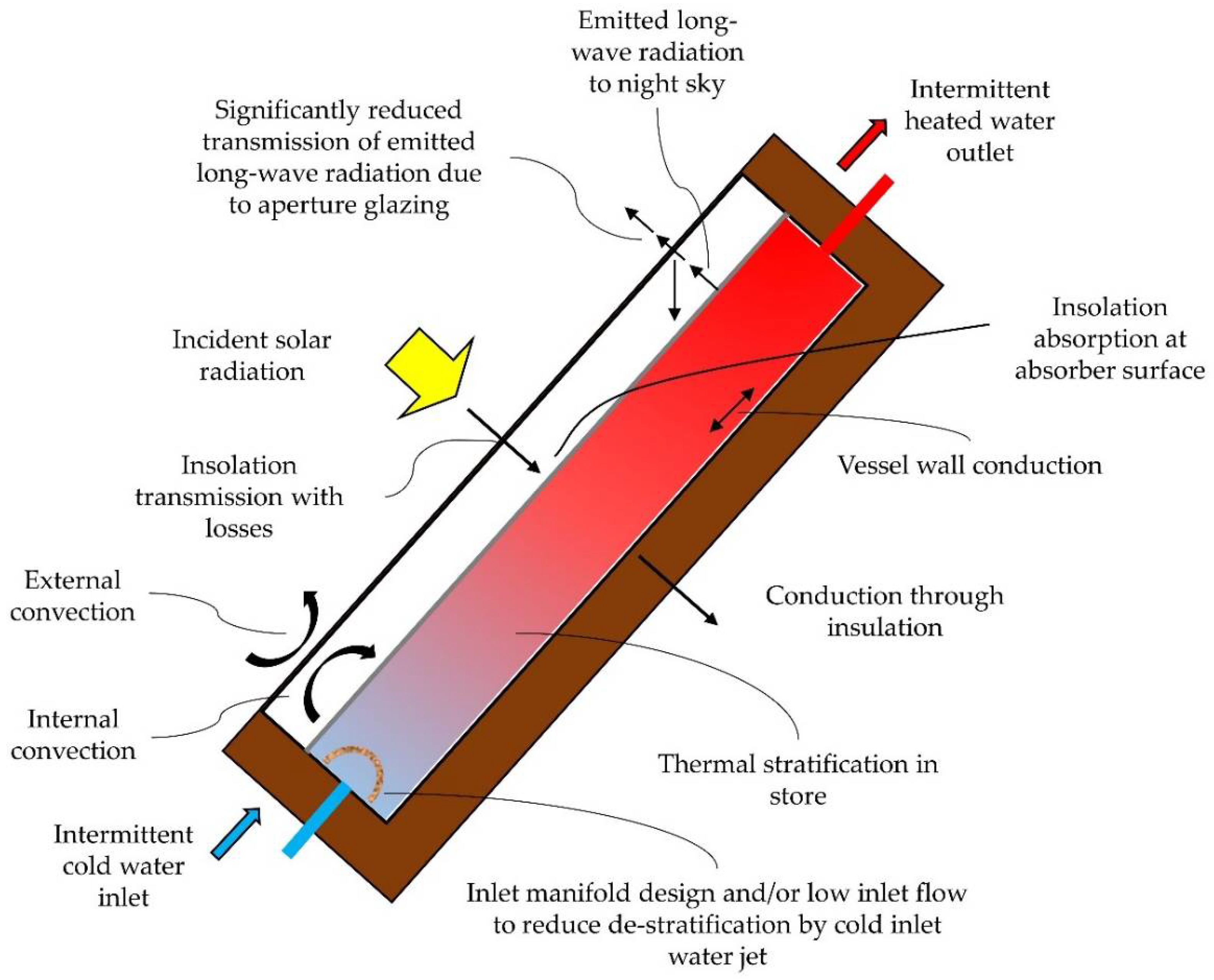
The evolution of solar water heaters (SWHs) has been an impressive journey beginning in America with the first of its kind, ‘The Climax Solar-Water Heater’, patented in 1891 [5]. However, once extensive oil and gas reserves were discovered research into these systems halted until the early 1970s [6]. Presently, interest in solar water heating has been revived in response to global initiatives aimed at the promotion of renewable energy technologies in order to mitigate greenhouse gas (GHG) emissions [7,8]. There are numerous different models of SWH systems but they all have the same goal—to deliver hot water to the end-user when required, efficiently, and at a reasonable cost. Figure 1 shows an ICSSWH and illustrates the general key components of a SWH: an absorber surface to collect incident solar radiation, a storage tank (either combined with the collector or a distributed system), glazing with high transmission, insulated housing for the collector/storage unit, and cold water inlet and hot water outlet pipes.
The three most common SWH designs are concentrating collectors, evacuated tube collectors, and flat-plate collectors. The choice of which design to employ can be determined by the environmental conditions and the heating requirements of the end-user. Flat-plate collectors have varying designs (serpentine, parallel tubes or ICSSWH) and, as the cheapest of the three options, are used extensively for domestic water heating applications due to the performance advantages relative to cost [9]. They collect both direct and diffuse radiation which is advantageous in overcast conditions, also solar tracking is not required thus lowering system cost and complexity. The majority of studies surrounding these systems aim to evaluate and optimise their performance, including optical efficiency, thermal efficiency, and heat retention. There have been a number of papers (see Table 1) over the last decade aiming to review these heat loss reduction strategies and to appraise the work being conducted in the area of thermal performance.
Table 1 provides a summary of recent review papers in the field of solar thermal systems, detailing the types of systems and the design aspects reviewed. Of the review papers listed, only a handful evaluate the array of thermal optimisation methods available in one article. Smyth et al. [6] present the most comprehensive review of the technical aspects of ICSSWH systems. Kumar and Rosen [10] also review a number of optimisation strategies, collating key literature. However, the main problem is the distributed nature of the information with regards to heat retention strategies and the need for that information to be updated. Therefore, the aim of this paper is to present an up-to-date, comprehensive review of the current research pertaining to the improvement in thermal performance and heat retention with a particular focus on ICSSWH systems.

3. Heat Gain and Retention Strategies

ICSSWH systems are the simplest of the SWH designs, combining the collector and storage tank into one compact unit. This creates direct contact between the working fluid (water, in direct systems, as it must be potable) and the absorber plate. As a result, ICSSWH are subject to heavy heat losses, especially during overcast and non-collection periods [21]. Figure 2 illustrates the heat transfer mechanisms in a typical ICSSWH system showing the number of ways heat can be lost. The collector surface absorbs solar radiation and converts it to heat which then gets transferred directly to the water through convection. Due to the buoyancy effect, thermal stratification builds up in the water body with the hottest water at the top of the tank where the majority of heat is lost through convection, conduction and radiation. Convective heat losses occur between the absorber plate and the glazing and the air cavity needs to be optimised to act as an insulating gap, promoting convective heat transfer to the collector whilst also minimising losses when ambient temperatures drop. Conductive heat loss from the back and side walls, as well as the absorber surface, is a major problem for ICSSWH systems and they need to be heavily insulated. Long-wave radiative heat losses have the largest impact and occur between the absorber plate and the glazing, suppressed to an extent by the air cavity. The glazing needs to have a very high transmissivity as well as optical efficiency to ensure as much incident solar radiation can reach the collector surface as possible whilst again minimising radiative losses. Numerous strategies exist to overcome these losses and to promote heat gain. The literature surrounding these methods of optimising thermal performance will be reviewed in greater detail in the following segments.

3.1. Additional Insulation

Insulation is a simple and effective way of retaining heat, particularly at night. The two main types of insulation are opaque and transparent. Opaque insulation is primarily used around the back and sides of the systems where ambient heat losses through conduction and convection are high but there is no need for transmittance of solar radiation [22,23]. A large percentage of heat is lost through the glazing as this needs to be exposed to gain solar irradiance. This can potentially be alleviated by partially insulating the air cavity, using transparent insulated glazing materials, and/or by applying an insulated cover during the night and non-collection periods.

3.1.1. Transparent Insulation Materials (TIMs)

TIMs represent a new class of thermal insulation used to reduce unwanted heat losses from air gaps and evacuated spaces. TIMs are transparent to solar irradiation yet they can provide good thermal insulation. Early attempts to use these materials, such as experimental work by McCracken [23], led to overall decreases in system efficiency, by ~20% during daytime collection, due to their poor solar transmittance (0.85 in this case). However, research and development of these materials has led to greater collector performances and they could be greatly beneficial in increasing the solar gain of thermal energy systems. TIMs include organic-based transparent foams, honeycomb or capillary structures, and inorganic glass foams (e.g., silica aerogel). There are numerous configurations available in terms of cellular geometry, as illustrated in Figure 3 [24].
Kaushika and Sumathy [24] conducted a review of solar TIMs, presented in Table 2. It was found that a honeycomb material had the highest efficiencies when compared with a single and double glazed system and a transparent slab of methyl methacrylate (MMA). It can also be seen that efficiency increases with TIM thickness.
Schmidt and Goetzberger [25] determined that, for a single-tube absorber mounted in an involute reflector, the ICS performance was almost constant for a TIM (polycarbonate honeycomb structure) thickness ranging from 50–150 mm. Chaurasia and Twidell [26] compared two identical ICS units, one with TIM and the other without. The system with TIM had a total heat loss factor of 1.03 W/m2K, with hot water at temperatures 8.5–9.5 °C higher the next morning, compared with 7.06 W/m2K for the glass only system. The study found that, by using TIM, storage efficiency was 24.7% higher; 39.8% compared to 15.1% without the TIM. Reddy and Kaushika [27] conducted a series of comparative studies on the effect of different TIM configurations for a rectangular ICSSWH. It was reported, and later corroborated [28,29], that an absorber-perpendicular configuration (transparent honeycomb structure immersed in an air layer) exhibited superior efficiencies over corresponding absorber-parallel configurations (multiple covers of glass/plastic films). Reddy and Kaushika [27] concluded that the double-wall structured polycarbonate TIM sheet was the most effective configuration and a system with a thickness of 10 cm can achieve average solar collection and storage efficiencies in the range of 20–40% and bulk water temperatures between 40 and 50 °C.

3.1.2. Opaque Insulation

A number of studies have experimentally reviewed the collector performance of fully-versus partially-exposed designs. Tripanagnostopoulos et al. [30] evaluated the performance of two double-vessel systems utilising asymmetric compound parabolic concentrator (CPC) reflectors where one had both tanks fully exposed while the other was partially exposed. The latter showed improved heat retention during non-collection periods but the fully exposed design exhibited greater collection efficiency. Smyth et al. [31] investigated two ICSSWH systems enclosed within a concentrating collector. One system was a fully exposed, 1.0 m long cylindrical tank and the other a 1.5 m long tank with the top third heavily insulated. Unlike Tripanagnostopoulos et al. [30], the insulated system exhibited a 13% increase in collection efficiency and increased thermal retention of up to 37% in the upper insulated section due to stratification. However, these results are perhaps reflecting the greater storage capacity and lower average water storage temperatures of the 1.5 m tank. Chaabane et al. [32] also found, through a numerical CFD study, that a partially insulated tank effectively retained heat during non-collecting periods. For the studied CPC mounted ICS system the authors found that the additional insulation did affect the optical efficiency, with slightly lower water temperatures observed–up to 7.5 °C difference between the insulated and non-insulated systems. However, this trade-off was worthwhile with higher temperatures (up to 7 °C) at the start of the collection period and a ~25% reduction in thermal losses.
Using an experimental set-up, Souza et al. [33] and Swiatek et al. [34] studied a parallelepiped ICSSWH system which was partially heated. Souza et al. [33] studied the effect on thermal stratification within a cavity with a heat flux applied only to bottom 0.2 m while Swiatek et al. [34] built on this and applied the heat flux to a 0.2 m section in the middle of the cavity. Beyond the heated zone, the front plate of the cavity in both studies was entirely insulated with extruded polystyrene. Souza et al. [33] found that by only heating a short section at the bottom of the cavity the evolution of thermal stratification within the tank was unsatisfactory with a maximum temperature difference of only 4.2 °C being reported. The adaptations made in the later study yielded enhanced levels of stratification, with a maximum temperature different of 20.1 °C [34].

3.1.3. Night Cover

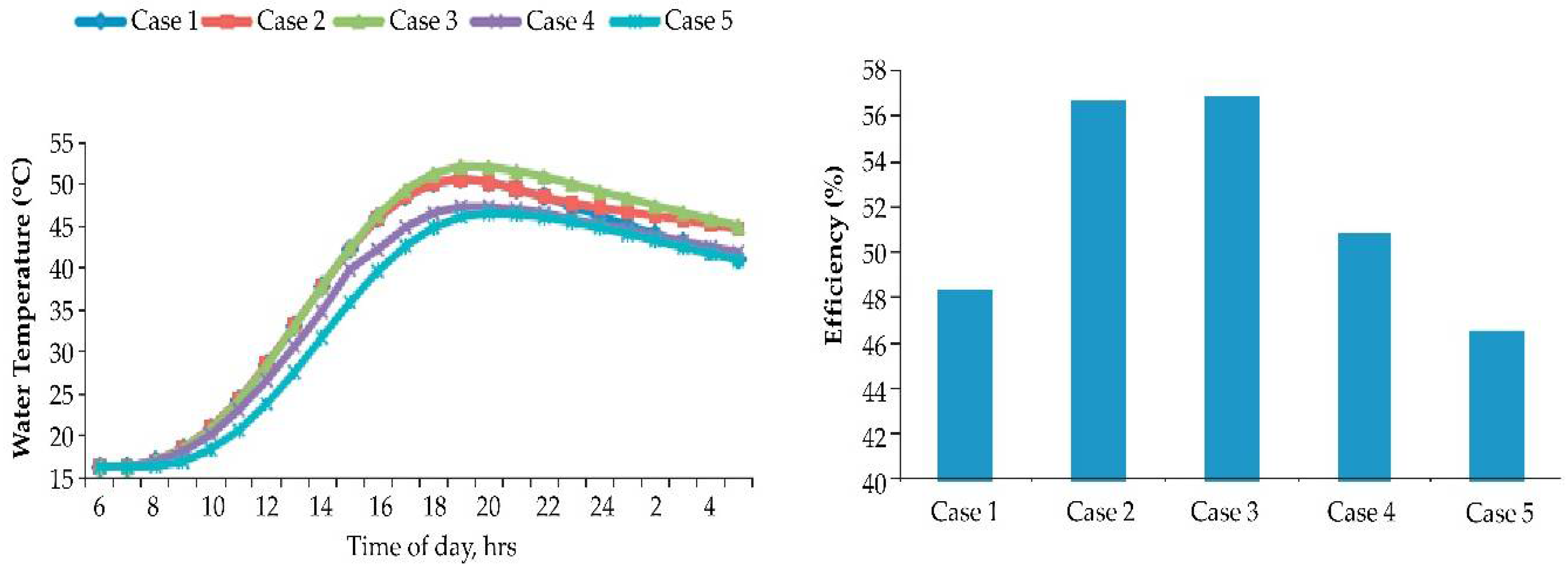
As well as insulating the air cavity, an insulating night cover can be utilised to reduce the issue of night-time heat losses. Kumar and Rosen [35] undertook a comparative performance investigation of rectangular ICSSWHs, assessing various heat loss reduction strategies. The following five cases were assessed: (1) single glass cover without night insulation; (2) single glass cover with night insulation cover; (3) double glass cover without night insulation cover; (4) transparent insulation with single glass cover; and (5) insulating baffle plate with single glass cover. They found that the TIM covered system reached lower absorber plate temperatures than single and double glazed cases due to the system receiving 10–15% less solar radiation. However, the TIM layer did help retain heat in the water store during the night, more so than the double glazing and significantly more than the single glazing. The single and double glazing perform in a similar manner during periods of insolation but at night the double glazed systems exhibits greater heat retention. Figure 4 illustrates the bulk water temperatures of the ICSSWH systems over a 24 h period showing that all five cases perform well. However, it is clear that Cases 2 and 3 maintain the highest temperatures and collector efficiencies, ranging from 57.1 to 79.4% and 57.6 to 81.2%, respectively (Figure 4).

3.2. Auxiliary Heating

Currently, average total hot water demand cannot be met by SWHs alone due to their diurnal nature and this is a problem for all solar thermal technologies, particularly in temperate climates such as Scotland. Garnier [36] tested the thermal performance of an ICSSWH with a 1 m2 absorber area and 50 L capacity. They discovered that the amount of energy required to supply a three-person household with a domestic hot water demand of 50 L/person/day at 55 °C is approximately 7.5 kWh/day, 2747 kWh/year. The amount of energy that the studied ICSSWH could contribute to this demand is shown in Figure 5; 1107 kWh, or 40% of the yearly energy demand. Therefore, the remaining 60% would need to be supplied by an auxiliary heater for diurnal demand.
A solar combi system (SCS) is one way to provide this additional heat requirement, if multiple solar thermal panels are unfeasible. Sarbu and Sebarchievici [37] summarise the major studies surrounding SCS in the literature. Drück and Hahne [38] conducted a comparative study of four hot water stores, each connected to a 10 m2 flat-plate collector area, where the back-up heat method is an immersed heat exchanger. The authors found that, for a well performing SCS, the most important factors are good thermal insulation and the optimal configuration of the hot water and auxiliary heating loops. By using an SCS over a conventional boiler, fractional energy savings of up to 21% can be realised.
A study in Jordan looked at the techno-economic feasibility of a SWH system with a built-in electric coil as an auxiliary heater compared to a gas geyser system [39]. The author found that the SWH with the integrated auxiliary heater was more economic due to the longer operational life expectancy and the number of days where the use of the electric coil is not required. If the number of days that electricity is used to provide the full daily hot water needs of a family is 120 or less the actual cost of the SWH system is less than the gas system, over the operational life.

Legionella/Freezing

Due to bacterial growth and freezing potential, most ICSSWHs are currently connected to a secondary auxiliary heating system. Hot water consumed by the end-user must be at a temperature that is high enough to kill any bacteria that may have formed in a system, the biggest concern being Legionella pneumophila. A review on behalf of the World Health Organisation [40] states that Legionella thrives at 36 °C and within a range of 25–50 °C. Water temperatures are required to exceed 60 °C for several minutes, at least once a day, to kill off any bacteria. Alternatively, draw off temperatures could be increased to 70 °C which destroys the bacteria instantly. This is potentially unattainable through solar insolation in a temperate climate such as Scotland, especially in winter months. Therefore, methods of back-up heating that work in conjunction with SWHs need to be incorporated.
Freezing is also an issue for ICSSWHs due to their high level of exposure to the elements. Smyth et al. [6] suggested that systems less than 100 mm deep were at greater risk of freezing and to prevent damage to the collector and storage tank the depth should be greater than this. Schmidt and Goetzberger [25] predicted that, for Northern European climates, the risk of freezing only occurs for ICS systems with a specific collector volume lower than ~70 L/m2 and that damage due to freezing only occurs if more than 20% of the ICS water content is frozen.

3.3. Baffle Plate/Inner Sleeve

Baffle plates have been used successfully in numerous ICSSWH designs as a method of improved thermal performance and heat retention. Various studies [41,42,43] have utilised an insulating plate, inserted parallel to the absorber plate, which creates a narrow channel with a thin layer of water which can reach much higher temperatures than the main water body. This system separates the downward and upward flow, thus decreasing mixing in the storage tank and promoting stratification. Once the water is heated it is deposited at the top of the tank, allowing colder water to be drawn up into the channel. Souza et al. [33] studied an ICS system incorporating a stratification plate running parallel to the absorber surface, which was only heated over the bottom 0.2 m. It was found that there was not a significant improvement in thermal stratification, with a maximum temperature difference of 4.2 °C being achieved. A follow-up study by Swiatek et al. [34] found that a shorter stratification plate (0.75 m compared to 0.9 m) in the 1.3 m rectangular system improved thermal stratification, with a maximum temperature difference of 20.1 °C. In contrast to Souza et al. [33], Swiatek et al. [34] heated a 0.2 m section in the middle of the tank and reduced the channel gap from 8 mm to 5 mm.
Ziapour and Aghamiri [44] looked at the effect of the channel width on collector efficiency in a two trapezoid ICSSWH system and found that a gap of 6 mm had the highest performance. Kumar and Rosen [35] studied a rectangular ICSSWH with an insulating baffle plate and single glazing. They found that absorber plate temperatures peaked at 63 °C during the day then suffered heavy losses during the night, dropping by approximately 30 °C. However, in the cylindrical ICSSWH configuration presented by Smyth et al. [31,45,46] it was found that by perforating the baffle plate, to avoid the heat build-up at the top of the channel that hinders flow, night-time heat losses could be reduced by 20% as the plate prevents reverse flow in the absence of a heat source. The operating principle of this perforated baffle plate is illustrated in Figure 6.
Sokolov and Vaxman [47] and, in a follow-up study, Vaxman and Sokolov [48] assessed a triangular system with a baffle plate and achieved an efficiency of 53%. Smyth et al. [31] presented results on an experimental analysis of a 1.5 m cylindrical ICS vessel, mounted within a reflector cavity, with the upper third heavily insulated and a perforated inner sleeve acting as a baffle. They showed that 60% of the thermal energy stored within the vessel could be retained over a 16 h non-collection period. The most efficient configuration was the 1.5 m vessel, with the top third insulated, no insulated cover during the non-charging phase, and a perforated inner sleeve. It outperformed the same configuration without the inner sleeve by 1.3% and the 1 m vessel with no insulated upper section and no inner sleeve by almost 7%.
El-Sebaii [49] studied the thermal performance of a shallow solar-pond, a batch system similar to ICSSWH, with an integrated baffle plate. Thermal performance was found to improve with the inclusion of the baffle plate. The highest daily efficiencies, up to 64.3%, were achieved using a plate without vents and positioned at approximately two-thirds of the total height of the collector. However, when a baffle plate with vents was used the performance is less dependent on its position within the pond. It was also shown that the baffle plate material had a negligible impact on water temperature throughout the pond, ranging from 58 °C to 59.1 °C to 60.3 °C for mica, aluminium and stainless steel, respectively. These results conformed to those previously reported by Kaushik et al. [41]. The baffle plate also allowed the pond to retain hot water overnight, reaching temperatures of 71 °C in the late afternoon and providing water at temperatures of 43 °C in the early morning the following day.

3.4. Fins

In 1907, Charles L. Haskell [50] patented a solar heater design incorporating ‘struts’ for improved heat conduction as well as structural stability (Figure 7). Since then, ‘struts’, or fins/extended surfaces, are commonly used in commercial evacuated tube and flat-plate collectors, protruding out from the collector pipes to enhance heat transfer to the working fluid. In ICSSWH systems, these fins can be placed directly into the water body, i.e., storage tank, and extend throughout the full depth allowing heat to be transferred through conduction to the areas that are not in close contact to the absorbing surface. Youcef-Ali [51] conducted an optimisation study evaluating the impact of fin length and various glazing types on thermal performance. The author studied a solar air collector with offset rectangular plate fin absorbers and found that they generated a higher heater transfer versus a flat-plate alone. The flat-plate collector, with double glazing, produced an efficiency of 38% against 64% for the offset absorber plate with 50 mm fins.
Gertzos and Caouris [52] optimised the arrangement of structural and functional parts in a flat-plate ICSSWH experimentally and numerically. Their aim was to eliminate the stagnation area near the geometrical centre of the stored water body and provide structural stability. The authors found that the presence of fins had no effect on the outlet water temperature as the increase in heat transfer rate was insignificant due to their small area, which was dwarfed by that of the tank. Li and Wu [53] studied the effect of extended fins on improving heat performance in shell-tube thermal energy storage units with phase change materials (PCMs). They found that by incorporating fins into the tube design the charging time could be shortened by up to 20%, depending on the PCM material used.
Work conducted by Muneer et al. [22], which was later ratified by Junaidi [54], led to the inclusion and optimisation of elongated fins inside a box-type ICSSWH to improve heat transfer throughout the water body. Junaidi [54] carried out simulations on both a finned and un-finned SWH and determined that the finned collector performed significantly better. Currie et al. [9] analysed the optimisation of fin length and thickness for an even heat distribution throughout the storage tank without disrupting flow patterns. The prototype subsequently tested by Garnier [55] utilised four 3 mm-thick aluminium fins mounted vertically in a square shaped collector. These were found to improve both the thermal performance and structural strength of the ICSSWH (Figure 8). A 13% increase in heat transfer was found, as a direct result of the fin installation. Mohsen and Akash [56] also studied the performance of a box-type ICSSWH with extended heat transfer fins. They found that the use of fins can improve the cumulative efficiency of the system by 9%, during the month of November in Jordan.
Following a numerical study by Chaabane et al. [57], the thermal performance of a cylindrical ICSSWH, mounted in a CPC, was improved by the inclusion of rectangular radial fins. This work was based on, and validated by, the experimental data presented by Chaouachi and Gabsi [58]. The fins create a modified surface that enhanced the convective heat transfer due to their higher characteristic length. This resulted in a double-edged sword with higher water temperatures and reduced thermal losses during the charging period but higher thermal losses during non-collection periods. The authors also noted a significant correlation between fin length and average water temperature, convective heat transfer, and heat retention. Three fin lengths were modelled, 15, 30 and 45 mm, and in all cases the 45 mm fins produced the best results during day-time operation. As the fin depth increases so does the availability of hot water; temperatures over 50 °C were maintained for 6.5 h and more than 10 h for a fin length of 15 mm and 45 mm, respectively. During night-time operation, the thermal loss coefficient is higher for the cases with fins, with a slight increase in the coefficient with increasing fin depth. However, the higher temperatures and longer heat retention gained during the day means a better overall performance for the finned ICS over un-finned. The author suggests a night insulation cover to combat the radiative heat losses.

3.5. Glazing

Solar water heaters generally include a glazed aperture over the absorber area with an optimised air gap to suppress upward convection and minimise heat losses, whilst maintaining a high transmissivity [59]. Glass is the most commonly used material as it is resistant to degradation from ultraviolet (UV) radiation and it has a very good transmittance to solar radiation (up to 90%), as well as a low transmittance to the thermal radiation emitted by the absorber [10,60]. Still, approximately 60% of heat loss in residential buildings can be attributed to the glazed areas [61] and this is no less important in an ICSSWH system. There are numerous ways to improve thermal performance and heat retention through the type and configuration of the glazed aperture including multilayer, vacuum, aerogel, and PCM glazing as well as low-emittance coatings. The most common options are reviewed below.

3.5.1. Glazing Layers

The study by Kumar and Rosen [35], reviewed in Section 3.1.3, looked at various heat retention strategies for a rectangular ICSSWH system. They found that a double glazed system maintained the highest temperatures and collector efficiencies which shows that thermal retention can be improved with multiple glazing layers. However, the amount of insolation transmitted to the absorber plate is reduced. In spite of this, Bishop [62] studied a high volume ICS water heater (two 170 L tanks), designed for use in freezing climates, which incorporated six glazing layers—one top sheet of low-iron glass and five sheets of high transmission polyester film with an overall solar transmittance of 70%. It was concluded that a twin-tank system with a total area of 2.88 m2 produced enough water at 50 °C, in January, for a family of four in the climate of Denver, Colorado, USA. This suggests that the reduced heat gain due to lower transmittance is, at least, balanced by the heat retained due to the greater thermal resistance of the multiple layers. In freezing climates, where solar insolation is presumably weak, this is highly beneficial as heat loss to the ambient environment will cripple any ICSSWH system. However, in locations where temperatures remain above freezing, with sufficient solar insolation, multiple glazing layers may reduce collector efficiency as well as significantly increase the cost of the unit.
Youcef-Ali [51] also advocated for a multi-glazed system in a study of a solar air collector. The author experimentally compared two types of transparent cover; double and triple glazed. The triple glazed system produced a better thermal performance reaching efficiencies up to 68% while the double glazed system peaked at 64%. The triple glazing shows a reduced transmission of solar energy but this is outweighed by the greater heat retention. AL-Khaffajy and Mossad [63] reviewed the optimisation of air cavities between glazing layers for a solar water heater with double glazing. This air gap has a strong influence on heat loss as it determines the level of convective motion between the absorber plate and subsequent layers of glazing. In the simulation, the air gap spacing between the absorber and the lower glass cover (L1) and between the lower and top glass cover (L2) ranged from 15–50 mm. It was found that the lowest heat loss was achieved with the combination of L1 = 40 mm and L2 = 25 mm.
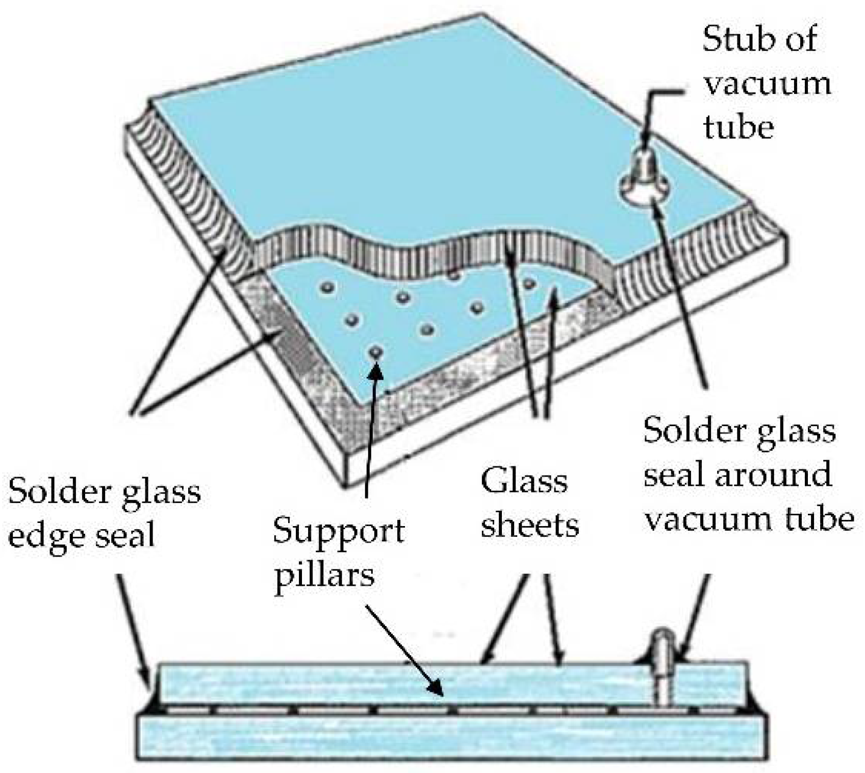
Another addition to multiple layers is vacuum glazing which offers a low heat loss, high optical transmittance solution. A double-glazed system with a vacuum gap between the glass sheets aims to eliminate conductive and convective heat transfer [61]. The issue of the glass layers collapsing in on themselves due to the high pressure of the vacuum can be combatted by inserting support pillars that have a minimal impact on optical performance [64]. Han et al. [65] found an overall heat transfer coefficient of 2.55 W/m2K for a 1 m2 double-glazed sample with a vacuum gap. The experiments considered the heat conduction through the support pillars and edge seal and the radiation between two glass sheets. As reported by Jelle et al. [66], SPACIA-21 a product from the Pilkington Company (Tokyo, Japan) (Figure 9), shows excellent promise with an overall heat loss coefficient of 0.70 W/m2K and a small external thickness of 21 mm, as opposed to a comparable multilayer glazing configuration at 40 mm. Cuce and Riffat [67] included translucent aerogel support pillars into a vacuum glazing design and modelled their impact on thermal performance and found a 44% reduction in the panels U-value. The authors indicated that a lower U-value could be reached if the number and distribution of the support pillars is optimised.
Vacuum glazing appears to be a promising option, however, there is an issue with conductive heat loss through the contiguous seal enclosing the glass sheets. Fang et al. [68] conducted a study on triple vacuum glazing and the impact of the edge seal on overall thermal transmission. They found that with smaller glazing size there is a larger ratio of heat conduction through the edge seal to that of the total glazing area. A 1 m2 sample demonstrated a total thermal transmission of 0.49 W/m2K compared to 0.65 W/m2K for 0.5 m2, equating to a 24.6% decrease. The width of the edge seal also made a significant impact on heat transmission. Increasing it from 3 mm to 10 mm resulted in a 24.7% and 25% increase in thermal transmission for indium and solder glass edge seals (with no frame rebate), respectively.

3.5.2. Selective Coatings/Glazing Material

A number of studies investigated the use of selective coatings on glass apertures [69,70,71,72,73]. A low-emissivity selective coating is designed to suppress infrared radiation exchange and acts as a selective reflector. Commonly used materials for these coatings have a transmission near zero for longwave infrared (i.e., energy radiated from warm objects) and low reflectivity for shortwave infrared (i.e., solar energy). Therefore, solar energy will be able to penetrate due to the low reflectance of the coating whilst heat emanating from a solar collector will be blocked by its low transmissivity. Bainbridge [72] found that double glazing with a selective transmission film worked as well as a night cover in reducing night-time heat losses. However, infrared reflective coatings reduce the transmission of solar radiation and Ahmadzadeh and Gascoigne [69] suggested that, for most operating conditions, the overall performance is better with plain glazing. Although, Muneer et al. [74] state that a low-emissivity coating has little effect on daylight transmissivity with a 5% reduction, from 80% to 75% transmission, when one layer is added to a double-glazed window. This may seem like a significant decrease but when compared to the almost 50% reduction in the U-value it may be a fair trade.
These selective coatings can aid transmission and retention of solar radiation, however, they come with a high production cost and the cost-benefit ratio is low [61]. Also, the coatings are susceptible to abrasion and dust accumulation over time, thus reducing solar radiation gain and overall system performance, as well as increasing maintenance [10]. It is possible to use plastic films or sheets instead of glass for the glazing material as they have high transmittance and low emittance of solar radiation. However, they are prone to deform at high temperatures and become opaque due to yellowing from UV radiation [60]. A polycarbonate sheet can also be used as it is weather-proof and UV-resistant [75]. A review by Kumar and Rosen [35] shows that either a double-glazed system or a single-glazed system with an insulated night-time cover are the most advantageous options in terms of heat gain and retention as well as economic feasibility.

3.6. Inlet Pipe Configuration

Thermal stratification within a water store is an essential contributor to overall efficiency. A fully mixed water body not only has a lower maximum temperature but also less capacity for heat gain. The level of stratification within a storage tank depends on the charging and discharging cycles of the SWH; the flow rates and water velocities; the size and shape of the system and; the size and location of the inlet and outlet pipes [6]. The design and configuration of the inlet pipe can have a significant impact on thermal stratification as it can be used to control flow velocities and thus reduce turbulent mixing [76,77,78]. Diffuser designs differ greatly and include slotted tubes, pipes with inverted cups, solid baffle plates, perforated circular plates, radial-flow disks, distributed nozzles, and perforated tubes [79]. Hegazy [80] experimentally tested three inlet geometries (Figure 10) and found that all the designs promoted good thermal stratification. The slotted inlet slightly outperformed the perforated and wedged pipes and the design is also simpler and cheaper to manufacture.
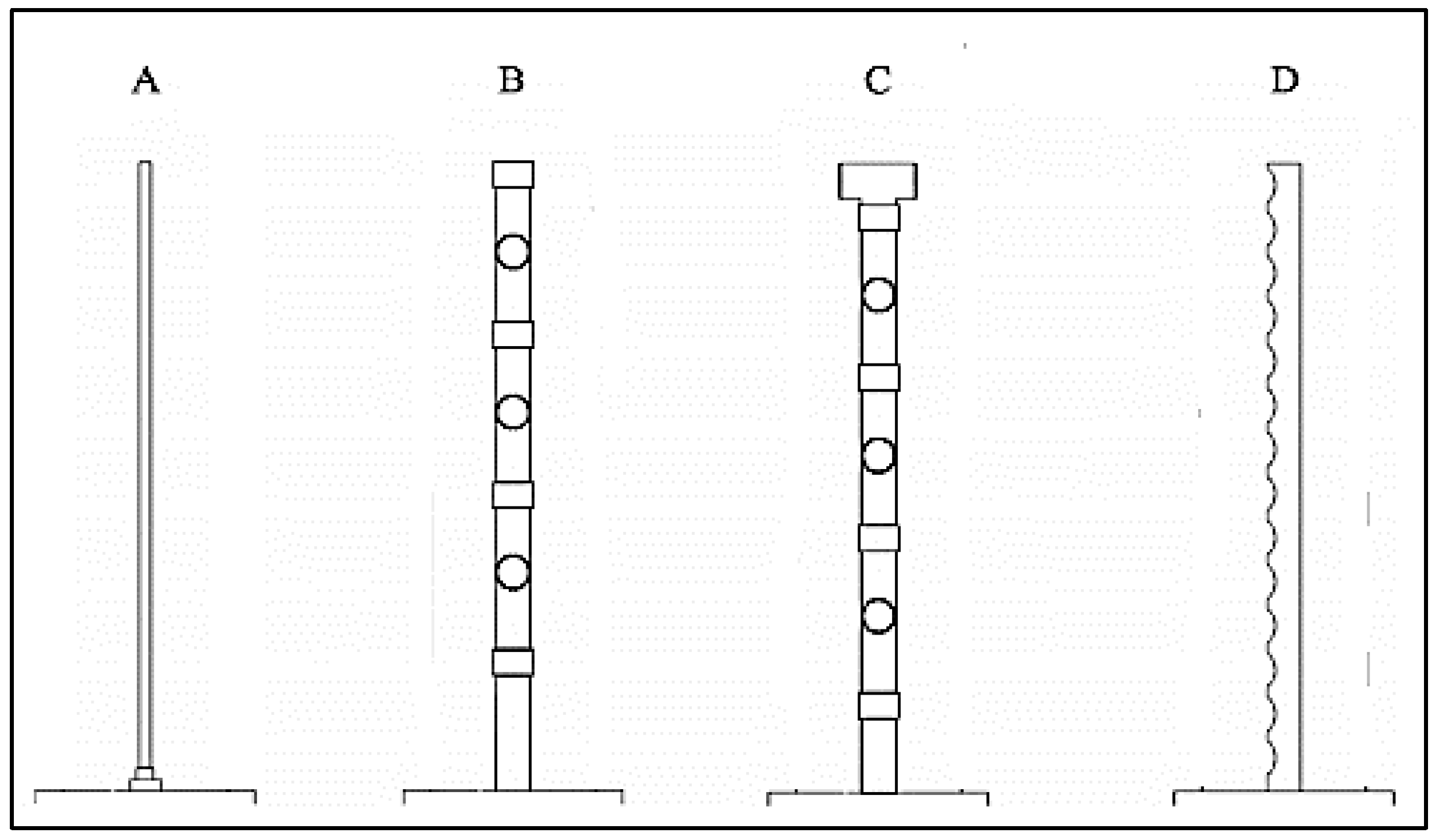
Chung et al. [81] analysed the impact of diffuser configuration on the thermal stratification within a rectangular water storage tank. Three diffuser types were studied—radial plate, radial adjusted plate, and H-beam. The results ratified the knowledge that diffuser shape has a significant impact on thermal performance and that the design should be tailored to the aspect ratio of the storage tank. In this case, the H-beam produced a thicker thermocline (and therefore higher thermal stratification) than the radial diffusers. The difference between the radial plates was minimal. Dragsted et al. [82] compared a new inlet diffuser design with well-established ones, illustrated in Figure 11.
The results found that performance depended on flow rate. At higher flow rates (4 L/min) designs B and C performed the best while design D worked better at lower flow rates (1 and 2 L/min). During charging periods design D showed the best performance due to the greater number of perforations.

3.7. Phase Change Materials (PCM)

Latent heat storage materials, also known as phase change materials (PCMs), are an increasingly popular method of extended heat energy storage and can be applied in many solar energy applications [83,84,85]. During daytime charging the PCM store excess thermal energy as latent heat by changing phase. During non-collection periods, as hot water is withdrawn for domestic use fresh, cold, water replaces it with no solar energy for heat gain. Therefore, the stored latent energy is released as the PCM change phase and revert back to their original state. There are different classes of PCM including organic compounds, inorganic materials, and eutectic mixtures [86]. One of the benefits of PCM is that, by storing excess energy, the heat losses that occur when the collector is at its highest temperature are reduced, thus enhancing system efficiency [87].
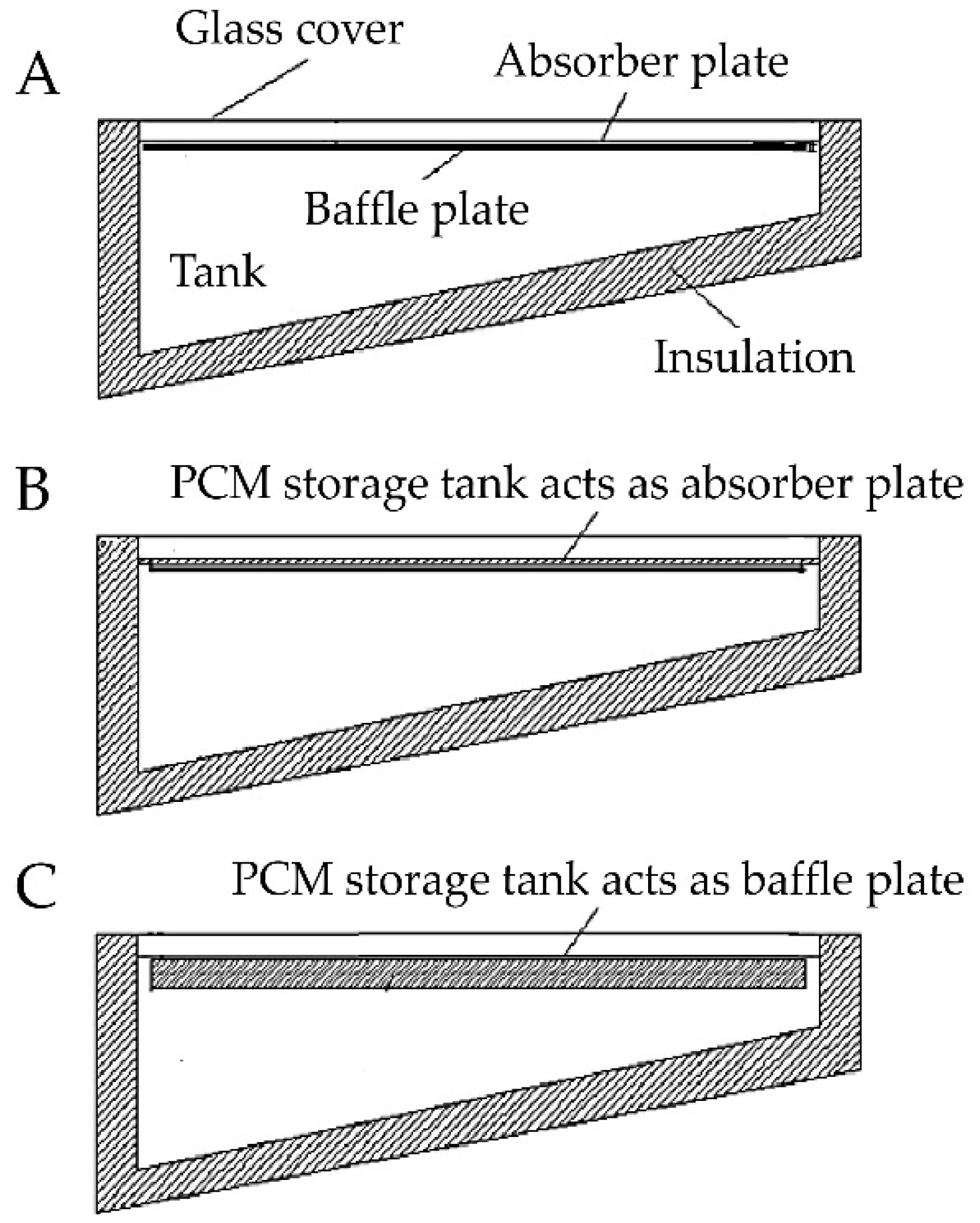
With regards to PCM integration into ICSSWH, a few studies have been conducted to determine the thermal performance [18,88,89]. Tarhan et al. [90] investigated the effect of PCM on the temperature distribution within the water tank. Three trapezoidal ICSSWH systems were analysed, one without PCM to act as a reference heater and two with different configurations of organic PCM (Figure 12).
The first set-up utilised myristic acid, in a PCM storage tank, as an absorber plate (Figure 12B) and in the second set-up lauric acid in the PCM storage tank was used as a baffle plate (Figure 12C). The configuration with myristic acid proved to have the highest overall performance with water temperature differences up to 4 °C after the cooling period. This is due to the solidification temperature of the myristic acid, it solidifies at 51–52 °C and acts as a thermal barrier so the absorber plate essentially becomes a night cover. The reference collector, with no PCM, reached higher peak temperatures during the collection period but this heat was lost during the night.
Chaabane et al. [89] carried out a numerical study of a CPC mounted ICSSWH system with two different PCM—myristic acid and RT42-graphite. The authors also found myristic acid to be the most beneficial as it reaches higher maximum temperatures during the day and allows better heat preservation during the night, with water temperatures almost 30 °C higher than a non-PCM system after 18 h of operation. The thermal efficiency of the system without PCM is only slightly higher during the collection period but drops below the PCM configurations overnight. Hamed et al. [86] also did a numerical study, analysing the charging and discharging performance of a rectangular ICSSWH. The type of PCM used in the calculations was not stated, only the thermophysical properties. As with the other studies the inclusion of a PCM resulted in a longer charging time, reaching lower peak temperatures, and higher available temperatures during the non-collection period with a maximum temperature difference of almost 9 °C.
However, the use of PCMs in thermal energy storage is limited and often unavailable on a commercial market due to economic and environmental constraints [85]. Choosing the right type of PCM and the position within an ICS system is crucial to its effective function [89]. Also, the evaporation associated with certain types of PCM requires enormous changes in volume of the storage materials making storage complex and impractical [86]. Many organic PCMs have a low rate of heat transfer as well as low thermal conductivity and for small scale applications, such as domestic solar water heating, the cost of this technology is still too great [85].

3.8. Reflectors

ICSSWH systems can absorb both diffuse and direct solar radiation and an easy way to enhance the level of diffuse radiation collected is to apply strategically positioned reflective surfaces. In terms of ICS systems, the most common configuration of collector and reflector is the compound parabolic concentrating (CPC) collector. A cylindrical water store is set into a reflective trough which reflects incident radiation to the absorber. Devanarayanan and Kalidasa Murugavel [91] conducted a comprehensive review of the development and progress surrounding ICSSWH with integrated CPC. The authors classified the different configurations of integrated compound parabolic concentrator storage solar water heater (ICPCSSWH) systems based on the associated absorber. The main conclusions from this review were that ICPCSSWH systems are cost-effective and simple to construct with a satisfactory thermal efficiency that can compete with flat-plate thermosyphonic units (FPTU). Also, they have a short response time across discharging and recharging. Drawbacks, however, include their lower optical efficiency, especially at lower sun angles (i.e., winter), high heat losses, particularly during non-collection periods, and only moderate thermal stratification within the water store.
Souliotis et al. [92,93] carried out research studies on ICSSWH systems mounted in CPC reflector troughs with the aim of assessing the thermal performance and enhancing the night-time heat retention. The authors found that seasonal variation has little impact on optical efficiency for the experimental location (Patras, Greece) with values ranging from 77% in winter to 79% in summer [92]. When compared with a FPTU, the ICS system has poorer heat retention with the bulk water temperature, after 24 h, being 7 °C lower. However, during the charging period the ICPCSSWH has a greater system efficiency and thermal stratification due, in part, to the partial vacuum in the annulus between the absorber and storage of the ICS unit. This added thermal diode improves the operation of the system but high thermal losses, poor stratification, and optical efficiency are still observed. These results were reiterated in a later study with a bulk water temperature difference of 12 °C between the FPTU and ICS models, after 24 h [93]. However, thermal losses can be improved by incorporating double glazing into the design.
Varghese et al. [94] carried out a study on a cylindrical ICPCSSWH in Delhi, India, with the aim of improving heat retention by including an air gap in the side walls (the arms of the CPC). They found maximum experimental efficiencies of 38% and water temperatures of 53 °C. By introducing an air gap the maximum outlet temperature can be enhanced and continues to rise even after collector efficiencies drop. This is due to the thermal barrier, created by the air gap, between the absorber and the ambient air which decreases the thermal loss coefficient by up to 52.5%, depending on water temperature.
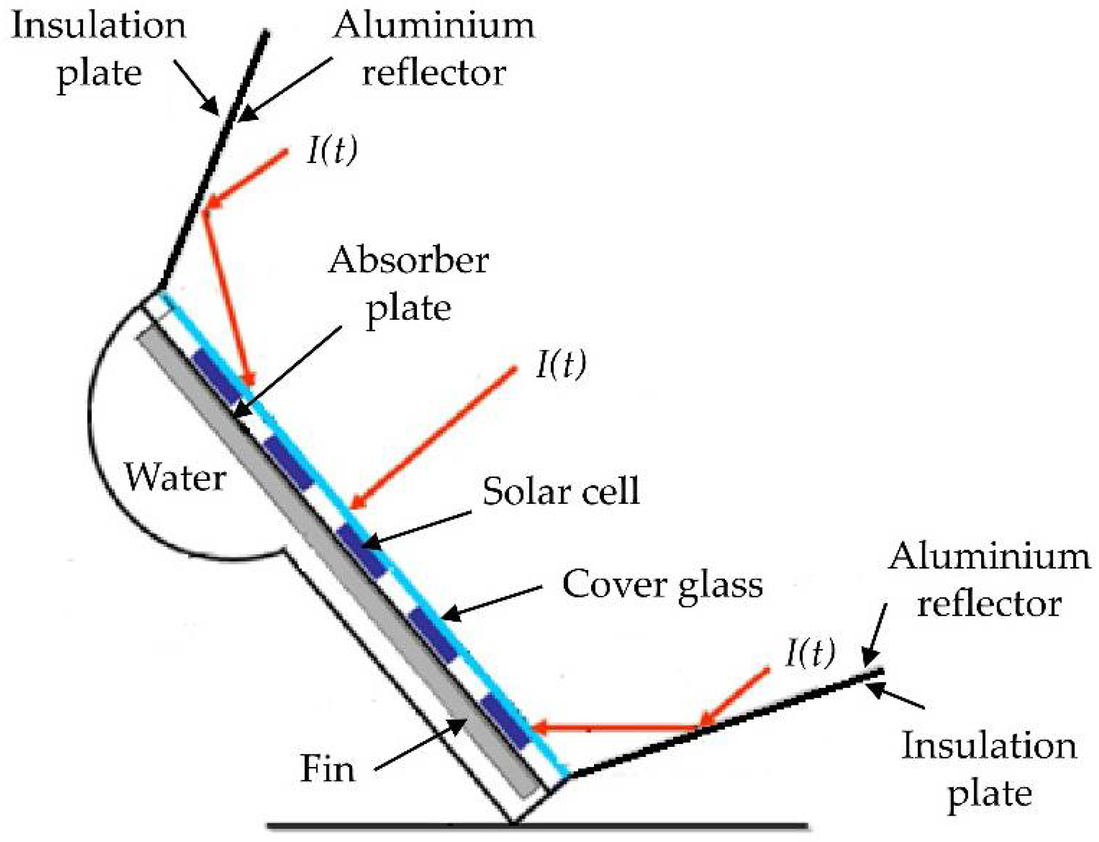
Not all reflector mounted ICS systems utilise cylindrical collectors, however. Ziapour et al. [95] analysed the performance improvement of a rectangular PV/T system which incorporated reflectors that acted as removable insulation covers (Figure 13). The findings of the numerical model showed that the reflectors effectively reduced the night-time heat losses whilst increasing the level of solar radiation incident on the absorber plate. With reflectors, peak diurnal temperatures reach 69.2 °C; 9.5 °C highly than a system without reflectors. Water temperatures in the morning (6 a.m.) are also much higher with values up to 54 °C compared to 31 °C, thus offering a 43% improvement. The angle at which the reflectors are mounted has a strong influence on the total solar radiation incident on the absorber plate and a model optimising these angles was presented.
Although reflectors have potential, their shape and size are not practical for mounting on a pitched roof. The impact on the aesthetics of the structure might be off-putting for prospective consumers. The issue of wind loading is also magnified with these ICS configurations as their bulky and protruding nature makes them more susceptible to higher wind loads. This would be especially prominent in the case of the latter study as the reflectors, which are open during the day, could be damaged in high winds. Ziapour et al. [95] made no mention of the impact of wind in their numerical study, however, this would be an important consideration under practical application.

3.9. Selective Absorber Surfaces

An absorbent coating is often used to enhance the absorption of solar radiation. Black paint is commonly used as it is a good absorber of radiation within the visible and infrared part of the spectrum and therefore absorbs the most heat. Due to the low emittance of a black object it can absorb up to 96% of incident insolation [60,96]. For greater absorptivity and lower emissivity, a spectrally selective absorber surface can be employed. Smyth et al. [6] conducted a thorough review of several studies that have verified the benefit of selective absorber coatings [72,97,98,99,100,101]. The reviewed studies demonstrated improved water temperatures but poor heat retention during non-collection periods, compared to a plain design [99,101]. Cummings and Clark [100] showed that the average annual delivered energy for a single-glazed selective absorber design would increase in the range of 26–44% compared with a basic design. This indicates the potential of selective surfaces and optimising the emittance of the coating could make up the small temperature differences observed [99,102].
Teixeira et al. [73] presented a numerical model that allows the selectivity of absorber coatings to be correlated with the collector efficiency. The analysed composite cermet coatings have high spectral selectivity, with absorption in the range of 0.88 to 0.94 and emissivity ranging from 0.15 to 0.04, and were subject to three different sputtering conditions—single layer, multilayers and gradient coatings. The study showed that a graded coating had much higher absorptivity, due to reduced reflectance, than a pure cermet film. Layered coatings also had much lower reflectance, and therefore greater absorptivity, for aluminium and copper surfaces, although glass did not follow this behaviour. For both cases reflectance is less than 10%, over the visible range of 380–780 nm associated with the luminance of daylight [103].
The type of coating used for the absorber surface is not the only consideration but also the profile; for example, whether it is planar or corrugated. Kumar and Rosen [104] reported on the thermal performance of an ICSSWH with a corrugated absorber surface. This surface has a higher characteristic length and, therefore, a higher surface area exposed to solar radiation. It was concluded that the corrugated surface had higher operating temperatures for a greater period than the plane surface but a marginally reduced system efficiency, as a result. As the corrugation depth increases from 0.4 mm to 1 mm, the maximum temperature of the water increases from 53 to 64 °C while the efficiency decreases from 46.8% to 42.4% (with night-time insulation) and 40% to 35% (without night insulation). At a corrugation depth of 1 mm average water temperatures are 5 to 10 °C higher than with a plane surface during collecting periods.

3.10. Storage Tank/Collector Material

3.10.1. Metals

Traditionally, SWHs have been constructed from metal due to their strength and durability. The most common are copper, stainless steel, and aluminium. Copper has the highest thermal conductivity at 385 W/m∙K but it is also the most expensive. Therefore, in the interests of developing a cost-effective solution stainless steel or aluminium are more often utilised [105]. In terms of structural strength, stainless steel outperforms aluminium which is a ‘soft’ metal and can deform at high temperature and pressure. Aluminium can also suffer galvanic corrosion when connected to conventional copper pipework whereas stainless steel is resistant to corrosion [105]. Aluminium does, however, have a much higher thermal conductivity at 237 W/m∙K compared to 14.9 W/m∙K for stainless steel [96]. Heat transfer and the thermal conductivity of the vessel material have a significant impact on thermal stratification within the water store. Vertical conduction in the tank walls, coupled with losses to the ambient environment, induces convective currents that rapidly degrade thermal stratification [6]. This suggests that a material with a lower thermal conductivity could be beneficial in reducing the convective heat motion, thus enhancing stratification. However, there is the trade-off of reduced transfer of absorbed heat to the water body.
Ziapour et al. [106] simulated and compared four different types of absorber for passive PV/T systems. Here, PV panels were mounted onto different absorber plate types of an ICSSWH—an aluminium plate with fins; aluminium without fins; Tedlar (a highly versatile polyvinyl fluoride polymer material) and; black painted glazing. The simulation results showed that the aluminium absorber plate with fins had the highest electrical and thermal efficiencies, with combined PV/T efficiencies up to 88% [106]. Garnier [36] modelled the impact of stainless steel versus aluminium on heat transfer, comparing aluminium thicknesses of 3 mm and 1.5 mm and 1.5 mm thick stainless steel, and found heat transfer rates of 67.3%, 63% and 25.3%, respectively. These computational results were found to be in close agreement with experimental data. Garnier [36] also conducted a monetary analysis and life cycle assessment of stainless steel versus aluminium systems. ICS systems strive to be a “green” technology, therefore, the embodied energy, embodied carbon, and recyclability must be taken into consideration. The author found that the embodied energy of stainless steel was 66% less than aluminium and, likewise, the embodied carbon was 26% lower with stainless steel over aluminium. This difference could be reduced if the percentage of recycled material in the aluminium is increased.

3.10.2. Polymer and Composite Materials

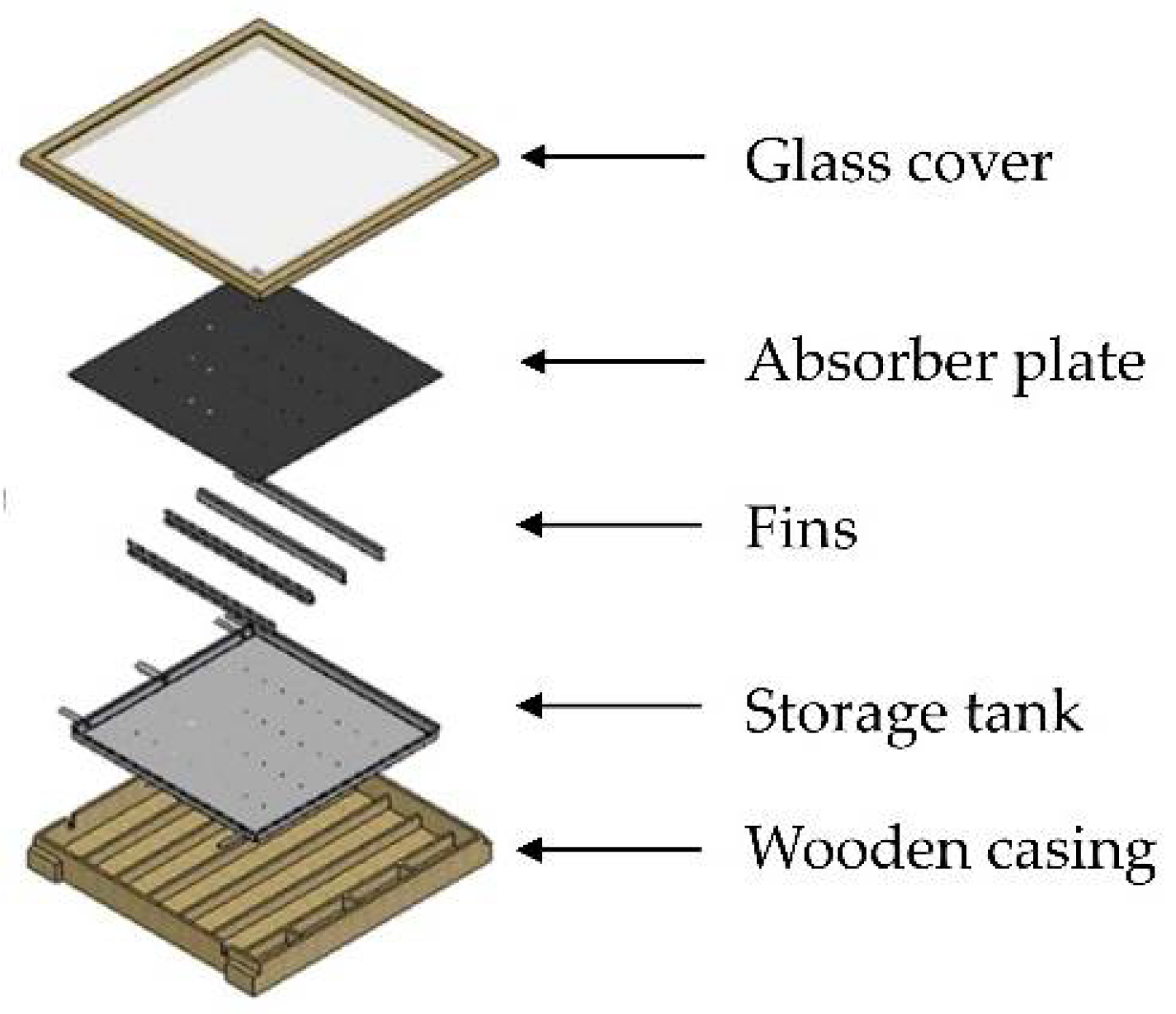
The use of solar thermal energy systems has increased dramatically in last decade yet the metal based collectors, despite a high thermal performance, are still relatively expensive to buy and install [17]. More recently, research has been undertaken on the use of polymer and composite materials for the ICSSWH components [75,107,108]. These have the potential to simplify ICSSWH construction as well as decrease the cost of the unit as a whole [75]. Polymers are light-weight and non-corrosive, which cannot be said for metal based materials [14]. The manufacture of the system would need to be altered in terms of welding, soldering, mechanical treatment, and assembly (moulding and gluing of the polymer composite). Frid et al. [75] looked at the use of polymer composite materials in ICSSWH construction, incorporating only three components—glazing, absorber plate, and storage tank/SWH casing (Figure 14). The glazing is weather-proof, UV-resistant, plate-type polycarbonate and the absorber plate is manufactured from a fibre-glass or carbon-filled plastic and coated with a selective absorber coating. The storage tank is a series of troughs and is integrated with the outer wall of the system (Figure 14), with the area between the two filled with thermal insulation, to reduce the number of parts in the unit.
This prototype demonstrated its in-situ operability, however, the engineering solutions applied in its construction are suitable only for low volume production, and thermal vacuum moulding of the polycarbonate glazing gave no guaranteed result [107]. This brings into question the mass reproducibility of the unit as well as its structural integrity. Also, the estimated minimum service lifetime for the casing, absorbing panel, and glue joints was 7 years at a cost of $70–90/m2 (receiving surface), an average or maximum expected lifetime was not mentioned [75]. While this is approximately half the cost of traditional materials, which are in the range of $150–200/m2 (prices commonly fluctuate), the unit also has half the lifetime with stainless steel and aluminium systems offering satisfactory performance for up to 20 years. There is an international effort to advance the use of polymer materials in SWH systems in order to lower the initial cost. However, more research needs to be done in terms of the structural integrity of the unit, their ability to resist UV degradation, and overheat protection of the absorber to prevent overrunning the maximum allowable temperature of the polymer [6,17]. Despite the flexibility and freeze tolerance of polymers they have a lower thermal conductivity than metals and a much shorter lifetime so in terms of the cost to benefit ratio metals still have the upper hand [14].

3.11. Thermal Diodes

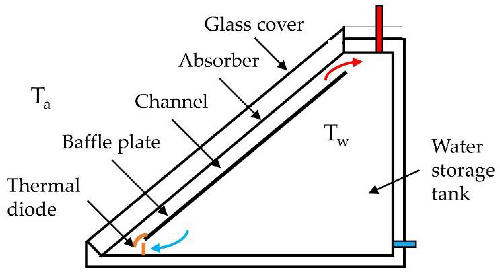
A thermal diode is a device which causes heat to flow preferentially in one direction and is a method of heat retention during the night and non-collecting periods, offering improved efficiencies and higher temperatures. Mohamad [42] introduced a simple thermal diode into triangular ICS systems with incorporated baffle plates. The thermal diode design is located at the base of the vessel, at the entry to the baffle channel, and consists of a light weight plastic ‘gate’ that prohibits reverse flow (Figure 15). Mohamad [42] showed that reverse circulation at night-time is prevented, particularly when storage temperatures are high, thus producing storage efficiencies of 68.6% and 53.3% with and without the diode, respectively.
Sopian et al. [109] introduced a thermal diode into their ICS design and the temperature drop in the storage tank overnight was reduced from 20 °C without a thermal diode to 10 °C with a diode. Creating an evacuated layer between the absorber plate and water cavity is another form of thermal diode. Souliotis et al. [92] studied an ICS vessel design mounted in a CPC reflector trough where an annulus between the cylinders is partially evacuated and contains a small amount of water, which changes phase at low temperature and produces vapour. This phase change creates a thermal diode transfer mechanism from the outer absorbing surface to the inner storage tank surface. Experimental results showed that the systems performance, when compared with a FPTU, is as effective both during day and night-time operation. More recently, Souliotis et al. [110] did a follow-up study on this CPC mounted ICSSWH system where extensive experimental data was collected over more than two years. The authors found that the PCM vapour pressure was a crucial parameter and the temperature increase during diurnal collection periods, at the optimal pressure, reaches 39 °C while the maximum heat loss during night-time operation is 13 °C with a thermal loss coefficient between 1.60 and 1.62 W/K. This performance was shown to be better than a commercial FPTU.
Smyth et al. [111] also conducted an experimental evaluation of a novel thermal diode in an ICSSWH to be used as a pre-heater. The collector was tested using a solar simulation facility and consisted of three concentric cylinders—the outer glazing, the middle absorbing surface and the inner storage tank (Figure 16). As in the latter study, the annular cavity between the absorbing surface and the storage tank is partially evacuated and contains a small amount of liquid/vapour PCM which acts as a thermal diode. The importance of a transparent aperture cover and cavity back insulation were highlighted as they are crucial in achieving the saturation temperature which promotes heat transfer through convection as opposed to radiation only. For the thermal diode mechanism to work effectively certain temperatures need to be reached and maintained to facilitate the evaporation-condensation cycle. Overall efficiencies were relatively poor, reaching a maximum of ~36%, but the impact on heat retention was considerable with a reduction in thermal losses of approximately 40%, compared with conventional ICS systems.

4. Conclusions

ICSSWH systems have a number of benefits over other solar thermal systems, namely that they do not require an additional water storage tank, are simple to construct and install and with fewer associated costs. A consequence of their more exposed nature is the increased level of heat loss, especially during non-collection periods. This review has presented the numerous innovations and developments in current research surrounding the improvement in the overall performance of these ICS systems, amongst others. We have reviewed and discussed the various heat retention strategies and the impact on thermal performance and efficiency, the associated heat loss mechanisms are summarised in Table 3. Some methods, such as selective absorber coatings, can have a positive effect on heat gain whilst the effect on heat losses is negligible and the same level of performance can be achieved by simpler and cheaper means, such as a night-time cover or double-glazing. Reflectors can aid the absorption of diffuse solar radiation during collection periods but have a limited impact on heat retention during the night. Also, their bulky size and appearance would make their installation difficult and unpleasant, especially for domestic consumers. Research is placing a heavy focus on PCM for thermal energy storage and they have shown some promise. However, their performance greatly depends on the chosen materials and their design and thermochemical properties. Furthermore, their cost and relative complexity to incorporate into ICSSWHs makes them an impractical solution for domestic hot water systems at present.
Potential methods to improve thermal performance that do not add significant cost and complexity to ICS systems include baffles, multiple glazing layers, additional insulation and fins. Baffles and fins promote the convection and conduction transfer of heat from the absorber to the water store while the glazing and insulation prevent convective and radiative heat losses. The combination of different strategies would be beneficial for the overall thermal performance of the system without significantly impacting the efficiency. This paper has gathered together the relevant and up-to-date research and developments surrounding the performance of ICSSWH systems, focusing on heat retention, with the aim to provide a concise summary of the current literature for researchers in this field. PCM are favoured as the saving grace for solar thermal storage. However, they are currently unfeasible for small-scale, domestic applications. So far, the benefits do not outweigh their cost, making them unsustainable. Promising avenues for further research that have emerged from this critical review include enhanced glazing systems, adding additional insulation to portions of the system, and incorporating baffle plates. Although not considered in this paper, a number of the reviewed studies noted the importance of flow rate and draw-off frequency on system efficiency. As such, this is an important consideration for the optimisation of any ICSSWH system and an interesting avenue for further research.

Author Contributions

R.S. conducted the research behind this review article and wrote the paper with substantial contributions from C.G. during the initial drafts. F.P. and J.C. made significant contributions which included comments, guidance, and help to complete the final draft.

Acknowledgments

The Resource Efficient Built Environment Lab (REBEL) kindly covered the costs to publish open access.

Conflicts of Interest

The authors declare no conflict of interest.

Nomenclature

CFDcomputational fluid dynamics
CPCcompound parabolic concentrator
FPTUflat plate thermosyphonic units
GHGgreenhouse gas
ICPCSSWHintegrated compound parabolic concentrator storage solar water heater
ICSintegrated collector-storage
ICSSWHintegrated collector-storage solar water heater
PCMphase change materials
PVPhotovoltaic
PV/Tphotovoltaic-thermal
SCSsolar combi system
SWHsolar water heater
TIMstransparent insulation materials

References

  1. United Nations. Paris Agreement; United Nations: New York, NY, USA, 2015; p. 3. [Google Scholar]
  2. Ellabban, O.; Abu-Rub, H.; Blaabjerg, F. Renewable energy resources: Current status, future prospects and their enabling technology. Renew. Sustain. Energy Rev. 2014, 39, 748–764. [Google Scholar] [CrossRef]
  3. Wheelhouse, P. Draft Scottish Energy Strategy: The Future of Energy in Scotland. 2017. Available online: http://www.gov.scot/Publications/2017/01/3414/downloads (accessed on 24 January 2018).
  4. Jaisankar, S.; Ananth, J.; Thulasi, S.; Jayasuthakar, S.T.; Sheeba, K.N. A comprehensive review on solar water heaters. Renew. Sustain. Energy Rev. 2011, 15, 3045–3050. [Google Scholar] [CrossRef]
  5. Kemp, C.M. Climax Solar Water Heater. US Patent no. 451384, 28 April 1891. [Google Scholar]
  6. Smyth, M.; Eames, P.C.; Norton, B. Integrated collector storage solar water heaters. Renew. Sustain. Energy Rev. 2006, 10, 503–538. [Google Scholar] [CrossRef]
  7. United Nations. Kyoto Protocol to the United Nations Framework Kyoto Protocol to the United Nations Framework. Rev. Eur. Community Int. Environ. Law 1998, 7, 214–217. [Google Scholar] [CrossRef]
  8. Intergovernmental Panel on Climate Change (IPCC). Climate Change 2014: Mitigation of Climate Change; IPCC: Geneva, Switzerland, 2014. [Google Scholar]
  9. Currie, J.; Garnier, C.; Muneer, T.; Grassie, T.; Henderson, D. Modelling bulk water temperature in integrated collector storage systems. Build. Serv. Eng. 2008, 29, 203–218. [Google Scholar] [CrossRef] [Green Version]
  10. Kumar, R.; Rosen, M.A. Review of solar water heaters with integrated collector-storage units. Int. J. Energy Environ. Econ. 2013, 21, 343–382. [Google Scholar]
  11. Raisul Islam, M.; Sumathy, K.; Ullah Khan, S. Solar water heating systems and their market trends. Renew. Sustain. Energy Rev. 2013, 17, 1–25. [Google Scholar] [CrossRef]
  12. Shukla, R.; Sumathy, K.; Erickson, P.; Gong, J. Recent advances in the solar water heating systems: A review. Renew. Sustain. Energy Rev. 2013, 19, 173–190. [Google Scholar] [CrossRef]
  13. Tian, Y.; Zhao, C.Y. A review of solar collectors and thermal energy storage in solar thermal applications. Appl. Energy 2013, 104, 538–553. [Google Scholar] [CrossRef] [Green Version]
  14. Ibrahim, O.; Fardoun, F.; Younes, R.; Louahlia-Gualous, H. Review of water-heating systems: General selection approach based on energy and environmental aspects. Build. Environ. 2014, 72, 259–286. [Google Scholar] [CrossRef]
  15. Buker, M.S.; Riffat, S.B. Building integrated solar thermal collectors—A review. Renew. Sustain. Energy Rev. 2015, 51, 327–346. [Google Scholar] [CrossRef]
  16. Souliotis, M.; Singh, R.; Papaefthimiou, S.; Lazarus, I.J.; Andriosopoulos, K. Integrated collector storage solar water heaters: Survey and recent developments. Energy Syst. 2015, 7, 49–72. [Google Scholar] [CrossRef]
  17. Suman, S.; Khan, M.K.; Pathak, M. Performance enhancement of solar collectors—A review. Renew. Sustain. Energy Rev. 2015, 49, 192–210. [Google Scholar] [CrossRef]
  18. Colangelo, G.; Favale, E.; Miglietta, P.; De Risi, A. Innovation in flat solar thermal collectors: A review of the last ten years experimental results. Renew. Sustain. Energy Rev. 2016, 57, 1141–1159. [Google Scholar] [CrossRef]
  19. Jamar, A.; Majid, Z.A.A.; Azmi, W.H.; Norhafana, M.; Razak, A.A. A review of water heating system for solar energy applications. Int. Commun. Heat Mass Transf. 2016, 76, 178–187. [Google Scholar] [CrossRef]
  20. Singh, R.; Lazarus, I.J.; Souliotis, M. Recent developments in integrated collector storage (ICS) solar water heaters: A review. Renew. Sustain. Energy Rev. 2016, 54, 270–298. [Google Scholar] [CrossRef]
  21. Grassie, T.; Junaidi, H.; Muneer, T.; Currie, J.; Henderson, D. Study of the Modified Built-in Storage (Integrated Collector Storage) Solar Water Heater for Scottish Weather Conditions. In EuroSun 2006; Groenhout: Antwerp, Belgium, 2006. [Google Scholar]
  22. Muneer, T.; Maubleu, S.; Asif, M. Prospects of solar water heating for textile industry in Pakistan. Renew. Sustain. Energy Rev. 2006, 10, 1–23. [Google Scholar] [CrossRef]
  23. McCracken, H. How to Build a Passive Solar Water Heater; Carlos: Alturas, CA, USA, 1978. [Google Scholar]
  24. Kaushika, N.D.; Sumathy, K. Solar transparent insulation materials: A review. Renew. Sustain. Energy Rev. 2003, 7, 317–351. [Google Scholar] [CrossRef]
  25. Schmidt, C.; Goetzberger, A. Single-tube integrated collector storage systems with transparent insulation and involute reflector. Sol. Energy 1990, 45, 93–100. [Google Scholar] [CrossRef]
  26. Chaurasia, P.B.L.; Twidell, J. Collector cum storage solar water heaters with and without transparent insulation material. Sol. Energy 2001, 70, 403–416. [Google Scholar] [CrossRef]
  27. Reddy, K.S.; Kaushika, N.D. Comparative study of transparent insulation materials cover systems for integrated-collector-storage solar water heaters. Sol. Energy Mater. Sol. Cells 1999, 58, 431–446. [Google Scholar] [CrossRef]
  28. Kaushika, N.D.; Reddy, K.S. Thermal design and field experiment of transparent honeycomb insulated integrated-collector-storage solar water heater. Appl. Therm. Eng. 1999, 19, 145–161. [Google Scholar] [CrossRef]
  29. Ghoneim, A.A. Performance optimization of solar collector equipped with different arrangements of square-celled honeycomb. Int. J. Therm. Sci. 2005, 44, 95–105. [Google Scholar] [CrossRef]
  30. Tripanagnostopoulos, Y.; Souliotis, M.; Nousia, T. Solar ICS systems with two cylindrical storage tanks. Renew. Energy 1999, 16, 665–668. [Google Scholar] [CrossRef]
  31. Smyth, M.; Eames, P.C.; Norton, B. Heat retaining integrated collector/storage solar water heaters. Sol. Energy 2003, 75, 27–34. [Google Scholar] [CrossRef]
  32. Chaabane, M.; Mhiri, H.; Bournot, P. Effect of the storage tank thermal insulation on the thermal performance of an integrated collector storage solar water heater (ICSSWH). Heat Mass Transf. 2014, 50, 1335–1341. [Google Scholar] [CrossRef]
  33. Souza, J.V.D.; Fraisse, G.; Pailha, M.; Xin, S. Experimental study of a partially heated cavity of an integrated collector storage solar water heater (ICSSWH). Sol. Energy 2014, 101, 53–62. [Google Scholar] [CrossRef]
  34. Swiatek, M.; Fraisse, G.; Pailha, M. Stratification enhancement for an integrated collector storage solar water heater (ICSSWH). Energy Build. 2015, 106, 35–43. [Google Scholar] [CrossRef]
  35. Kumar, R.; Rosen, M.A. Comparative performance investigation of integrated collector-storage solar water heaters with various heat loss reduction strategies. Int. J. Energy Res. 2011, 35, 1179–1187. [Google Scholar] [CrossRef]
  36. Garnier, C. Performance Measurement and Mathematical Modelling of Integrated Solar Water Heaters. Ph.D. Thesis, Edinburgh Napier University, Scotland, UK, 2009. [Google Scholar]
  37. Sarbu, I.; Sebarchievici, C. Chapter 5—Solar Water and Space-Heating Systems, 1st ed.; Academic Press: Cambridge, MA, USA, 2017; ISBN 9780128116623. [Google Scholar]
  38. Drück, H.; Hahne, E. Test and Comparison of Hot Water Stores for Solar Combisystems. In Proceedings of the EuroSun98-The second ISES-Europe Solar Congress, Portoroz, Slovenia, 14–17 September 1998. [Google Scholar]
  39. Kablan, M.M. Techno-economic analysis of the Jordanian solar water heating system. Energy 2004, 29, 1069–1079. [Google Scholar] [CrossRef]
  40. World Health Organization (WHO). Legionella and the Prevention of Legionellosis; Bartam, J., Pond, K., Eds.; WHO: Geneva, Switzerland, 2007; ISBN 9241562978. [Google Scholar]
  41. Kaushik, S.C.; Kumar, R.; Garg, H.P. Effect of baffle plate on the performance of a triangular built-in-storage solar water heater. Energy Convers. Manag. 1995, 36, 337–342. [Google Scholar] [CrossRef]
  42. Mohamad, A.A. Integrated Solar Collector—Storage Tank System with Thermal Diode. Sol. Energy 1997, 61, 211–218. [Google Scholar] [CrossRef]
  43. Faiman, D.; Hazan, H.; Laufer, I. Reducing the heat loss at night from solar water heaters of the integrated collector-storage variety. Sol. Energy 2001, 71, 87–93. [Google Scholar] [CrossRef]
  44. Ziapour, B.M.; Aghamiri, A. Simulation of an enhanced integrated collector-storage solar water heater. Energy Convers. Manag. 2014, 78, 193–203. [Google Scholar] [CrossRef]
  45. Smyth, M.; Eames, P.C.; Norton, B. A comparative performance rating for an integrated solar collector/storage vessel with inner sleeves to increase heat retention. Sol. Energy 1999, 66, 291–303. [Google Scholar] [CrossRef]
  46. Smyth, M.; Eames, P.C.; Norton, B. Annual performance of heat retaining integrated collector/storage solar water heaters in a northern maritime climate. Sol. Energy 2001, 70, 391–401. [Google Scholar] [CrossRef]
  47. Sokolov, M.; Vaxman, M. Analysis of an integral compact solar water heater. Sol. Energy 1983, 30, 237–246. [Google Scholar] [CrossRef]
  48. Vaxman, M.; Sokolov, M. Experiments with an integral compact solar water heater. Sol. Energy 1985, 34, 447–454. [Google Scholar] [CrossRef]
  49. El-Sebaii, A.A. Thermal performance of a shallow solar-pond integrated with a baffle plate. Appl. Energy 2005, 81, 33–53. [Google Scholar] [CrossRef]
  50. Haskell, C.L. Solar Heater. U.S. Patents 842658A, 29 January 1907. [Google Scholar]
  51. Youcef-Ali, S. Study and optimization of the thermal performances of the offset rectangular plate fin absorber plates, with various glazing. Renew. Energy 2005, 30, 271–280. [Google Scholar] [CrossRef]
  52. Gertzos, K.P.; Caouris, Y.G. Optimal arrangement of structural and functional parts in a flat plate integrated collector storage solar water heater (ICSSWH). Exp. Therm. Fluid Sci. 2008, 32, 1105–1117. [Google Scholar] [CrossRef]
  53. Li, Z.; Wu, Z.G. Analysis of HTFs, PCMs and fins effects on the thermal performance of shell-tube thermal energy storage units. Sol. Energy 2015, 122, 382–395. [Google Scholar] [CrossRef]
  54. Junaidi, H.A. Optimized Solar Water Heater for Scottish Weather Conditions. Ph.D. Thesis, Edinburgh Napier University, Edinburgh, UK, 2007. [Google Scholar]
  55. Garnier, C.; Currie, J.I.; Muneer, T.; Girard, A. Computational study of an integrated collector storage solar water heater. In Proceedings of the Eurosun 2008, Lisbon, Portugal, 7–10 October 2008; pp. 1–8. [Google Scholar]
  56. Mohsen, M.S.; Akash, B.A. On integrated solar water heating system. Int. Commun. Heat Mass Transf. 2002, 29, 135–140. [Google Scholar] [CrossRef]
  57. Chaabane, M.; Mhiri, H.; Bournot, P. Thermal performance of an integrated collector storage solar water heater (ICSSWH) with a storage tank equipped with radial fins of rectangular profile. Heat Mass Transf. Stoffuebertragung 2013, 49, 107–115. [Google Scholar] [CrossRef]
  58. Chaouachi, B.; Gabsi, S. Experimental study of integrated collector storage solar water heater under real conditions. Renew Energy Rev. 2006, 9, 75–82. [Google Scholar]
  59. Duffie, J.; Beckman, W. Solar Engineering of Thermal Processes, 3rd ed.; Wiley: Hoboken, NJ, USA, 2006; Volume 116, ISBN 1118418123. [Google Scholar]
  60. Norton, B.; Lo, S. Anatomy of a solar collector. Refocus 2006, 7, 32–35. [Google Scholar] [CrossRef]
  61. Cuce, E.; Riffat, S.B. A state-of-the-art review on innovative glazing technologies. Renew. Sustain. Energy Rev. 2015, 41, 695–714. [Google Scholar] [CrossRef]
  62. Bishop, R.C. Superinsulated batch heaters for freezing climates. In Proceedings of the Eighth National Passive Solar Conference, Santa Fe, NM, USA, 7–9 September 1983; pp. 807–810. [Google Scholar]
  63. AL-Khaliffajy, M.; Mossad, R. Optimization of the Air Gap Spacing in a Solar Water Heater with Double Glass. In Proceedings of the 9th Australasian Heat and Mass Transfer Conference, Melbourne, Australia, 2–4 November 2011. [Google Scholar]
  64. NSG Group Nippon Sheet Glass Spacia—The Principle. Available online: http://www.nsg-spacia.co.jp/tech/index.html (accessed on 24 January 2018).
  65. Han, Z.M.; Bao, Y.W.; Wu, W.D.; Liu, Z.; Liu, X.G.; Tian, Y. Evaluation of thermal performance for vacuum glazing by using three-dimensional finite element model. Key Eng. Mater. 2012, 492, 328–332. [Google Scholar] [CrossRef]
  66. Jelle, B.P.; Hynd, A.; Gustavsen, A.; Arasteh, D.; Goudey, H.; Hart, R. Fenestration of today and tomorrow: A state-of-the-art review and future research opportunities. Sol. Energy Mater. Sol. Cells 2012, 96, 1–28. [Google Scholar] [CrossRef] [Green Version]
  67. Cuce, E.; Riffat, S.B. Aerogel-Assisted Support Pillars for Thermal Performance Enhancement of Vacuum Glazing: A CFD Research for a Commercial Product. Arab. J. Sci. Eng. 2015, 40, 2233–2238. [Google Scholar] [CrossRef]
  68. Fang, Y.; Hyde, T.J.; Hewitt, N. Predicted thermal performance of triple vacuum glazing. Sol. Energy 2010, 84, 2132–2139. [Google Scholar] [CrossRef]
  69. Ahmadzadeh, J.; Gascoigne, M. Efficiency of solar collectors. Energy Convers. Manag. 1976, 16, 13–17. [Google Scholar] [CrossRef]
  70. Wozniak, S.J. Solar Heating Systems for the UK: Design, Installation and Economic Aspects; Building Research Establishment: Watford, UK, 1979. [Google Scholar]
  71. Lefkow, A.R.; Lee, J.C. Selective IR reflective coatings. In Proceedings of the Annual DOE Active Solar Heating and Cooling Contractors Review Meeting, Incline Village, NV, USA, 26–28 March 1980. [Google Scholar]
  72. Bainbridge, D.A. Integral passive solar water heater performance. In Proceedings of the Sixth National Passive Solar Conference, Portland, OR, USA, 8–12 September 1981; pp. 163–167. [Google Scholar]
  73. Teixeira, V.; Sousa, E.; Costa, M.F.; Nunes, C.; Rosa, L.; Carvalho, M.J.; Collares-Pereira, M.; Roman, E.; Gago, J. Spectrally selective composite coatings of Cr-Cr2O3 and Mo-Al2O3 for solar energy applications. Thin Solid Films 2001, 392, 320–326. [Google Scholar] [CrossRef]
  74. Muneer, T.; Adodahab, N.; Weir, G.; Kubie, J. Windows in Buildings; Architectural Press: New York, NY, USA, 2000. [Google Scholar]
  75. Frid, S.E.; Arsatov, A.V.; Oshchepkov, M.Y. Engineering solutions for polymer composites solar water heaters production. Therm. Eng. 2016, 63, 399–403. [Google Scholar] [CrossRef]
  76. Lavan, Z.; Thompson, J. Experimental study of thermally stratified hot water storage tanks. Sol. Energy 1977, 19, 519–524. [Google Scholar] [CrossRef]
  77. Zurigat, Y.H.; Ghajar, A.J.; Moretti, P.M. Stratified thermal storage tank inlet mixing characterization. Appl. Energy 1988, 30, 99–111. [Google Scholar] [CrossRef]
  78. Carlsson, P.F. Heat storage for large low flow solar heating systems. In Proceedings of the ISES Solar World Conference; Hungarian Energy Society: Budapest, Hungary, 1993; pp. 441–445. [Google Scholar]
  79. Hegazy, A.A.; Diab, M.R. Performance of an improved design for storage-type domestic electrical water-heaters. Appl. Energy 2002, 71, 287–306. [Google Scholar] [CrossRef]
  80. Hegazy, A.A. Effect of inlet design on the performance of storage-type domestic electrical water heaters. Appl. Energy 2007, 84, 1338–1355. [Google Scholar] [CrossRef]
  81. Chung, J.D.; Cho, S.H.; Tae, C.S.; Yoo, H. The effect of diffuser configuration on thermal stratification in a rectangular storage tank. Renew. Energy 2008, 33, 2236–2245. [Google Scholar] [CrossRef]
  82. Dragsted, J.; Furbo, S.; Dannemand, M.; Bava, F. Thermal stratification built up in hot water tank with different inlet stratifiers. Sol. Energy 2017, 147, 414–425. [Google Scholar] [CrossRef]
  83. Prabhu, P.A.; Shinde, N.N.; Patil, P. Review of Phase Change Materials for Thermal Energy Storage Applications. Int. J. Eng. Res. Appl. 2012, 2, 871–875. [Google Scholar]
  84. Pereira da Cunha, J.; Eames, P. Thermal energy storage for low and medium temperature applications using phase change materials—A review. Appl. Energy 2016, 177, 227–238. [Google Scholar] [CrossRef] [Green Version]
  85. Pandey, A.K.; Hossain, M.S.; Tyagi, V.V.; Abd Rahim, N.; Selvaraj, J.A.L.; Sari, A. Novel approaches and recent developments on potential applications of phase change materials in solar energy. Renew. Sustain. Energy Rev. 2018, 82, 281–323. [Google Scholar] [CrossRef]
  86. Hamed, M.; Fallah, A.; Ben Brahim, A. Numerical analysis of charging and discharging performance of an integrated collector storage solar water heater. Int. J. Hydrogen Energy 2017, 42, 8777–8789. [Google Scholar] [CrossRef]
  87. Haillot, D.; Nepveu, F.; Goetz, V.; Py, X.; Benabdelkarim, M. High performance storage composite for the enhancement of solar domestic hot water systems. Part 2: Numerical system analysis. Sol. Energy 2012, 86, 64–77. [Google Scholar] [CrossRef]
  88. Al-Kayiem, H.H.; Lin, S.C. Performance evaluation of a solar water heater integrated with a PCM nanocomposite TES at various inclinations. Sol. Energy 2014, 109, 82–92. [Google Scholar] [CrossRef]
  89. Chaabane, M.; Mhiri, H.; Bournot, P. Thermal performance of an integrated collector storage solar water heater (ICSSWH) with phase change materials (PCM). Energy Convers. Manag. 2014, 78, 897–903. [Google Scholar] [CrossRef]
  90. Tarhan, S.; Sari, A.; Yardim, M.H. Temperature distributions in trapezoidal built in storage solar water heaters with/without phase change materials. Energy Convers. Manag. 2006, 47, 2143–2154. [Google Scholar] [CrossRef]
  91. Devanarayanan, K.; Kalidasa Murugavel, K. Integrated collector storage solar water heater with compound parabolic concentrator—Development and progress. Renew. Sustain. Energy Rev. 2014, 39, 51–64. [Google Scholar] [CrossRef]
  92. Souliotis, M.; Quinlan, P.; Smyth, M.; Tripanagnostopoulos, Y.; Zacharopoulos, A.; Ramirez, M.; Yianoulis, P. Heat retaining integrated collector storage solar water heater with asymmetric CPC reflector. Sol. Energy 2011, 85, 2474–2487. [Google Scholar] [CrossRef]
  93. Souliotis, M.; Chemisana, D.; Caouris, Y.G.; Tripanagnostopoulos, Y. Experimental study of integrated collector storage solar water heaters. Renew. Energy 2013, 50, 1083–1094. [Google Scholar] [CrossRef]
  94. Varghese, J.; Samsher, M.K. A parametric study of a concentrating integral storage solar water heater for domestic uses. Appl. Therm. Eng. 2017, 111, 734–744. [Google Scholar] [CrossRef]
  95. Ziapour, B.M.; Palideh, V.; Mokhtari, F. Performance improvement of the finned passive PVT system using reflectors like removable insulation covers. Appl. Therm. Eng. 2016, 94, 341–349. [Google Scholar] [CrossRef]
  96. Incropera, F.P.; DeWitt, D.P.; Bergmann, T.L.; Lavine, A.S. Principles of Heat and Mass Transfer, 7th ed.; Wiley & Sons: New York, NY, USA, 2013. [Google Scholar]
  97. Stickney, B.L.; Nagy, C. Performance comparisons of several passive solar water heaters. In Proceedings of the Fifth National Passive Solar Conference, Amherst, MA, USA, 19–26 October 1980; pp. 1071–1075. [Google Scholar]
  98. Burton, J.W.; Zweig, P. Side by side comparison of integral passive solar water heaters. In Proceedings of the Sixth National Passive Solar Conference, Portland, OR, USA, 8 September 1981; pp. 136–140. [Google Scholar]
  99. Tiller, J.S.; Wochatz, V. Performance of integrated passive solar water heaters (Breadbox-type) under varying design conditions in the South-eastern US. In Proceedings of the Seventh National Passive Solar Conference, Knoxville, TN, USA, 30 August–1 September 1982; pp. 975–980. [Google Scholar]
  100. Cummings, J.; Clark, G. Performance of integrated passive solar water heaters in US climates. In Proceedings of the Eighth National Passive Solar Conference, Santa Fe, NM, USA, 7–9 September 1983; pp. 791–796. [Google Scholar]
  101. Fasulo, A.; Odicino, L.; Perello, D. Development of CPC with low thermal losses. Sol. Wind Technol. 1987, 4, 157–162. [Google Scholar] [CrossRef]
  102. Tripanagnostopoulos, Y.; Yianoulis, P. Integrated collector-storage systems with suppressed thermal losses. Sol. Energy 1992, 48, 31–43. [Google Scholar] [CrossRef]
  103. Ghosh, A.; Norton, B. Interior colour rendering of daylight transmitted through a suspended particle device switchable glazing. Sol. Energy Mater. Sol. Cells 2017, 163, 218–223. [Google Scholar] [CrossRef]
  104. Kumar, R.; Rosen, M.A. Thermal performance of integrated collector storage solar water heater with corrugated absorber surface. Appl. Therm. Eng. 2010, 30, 1764–1768. [Google Scholar] [CrossRef]
  105. Gardner, L. The use of stainless steel in structures. Prog. Struct. Eng. Mater. 2005, 7, 45–55. [Google Scholar] [CrossRef] [Green Version]
  106. Ziapour, B.M.; Palideh, V.; Baygan, M. Performance comparison of four passive types of photovoltaic-thermal systems. Energy Convers. Manag. 2014, 88, 732–738. [Google Scholar] [CrossRef]
  107. Popel’O, S.; Frid, S.E.; Mordynskii, A.V.; Suleimanov, M.Z.; Arsatov, A.V.; Oschepkov, M.Y. Results of the development of a solar accumulation-type water heater made of polymer and composite materials. Therm. Eng. 2013, 60, 267–269. [Google Scholar] [CrossRef]
  108. Oshchepkov, M.Y.; Frid, S.E. Modeling of the Warm Water Displacement from Stratified Tanks of Integrated Collector Storage Solar Water Heaters. Appl. Sol. Energy 2016, 52, 173–177. [Google Scholar] [CrossRef]
  109. Sopian, K.; Syahri, M.; Abdullah, S.; Othman, M.Y.; Yatim, B. Performance of a non-metallic unglazed solar water heater with integrated storage system. Renew. Energy 2004, 29, 1421–1430. [Google Scholar] [CrossRef]
  110. Souliotis, M.; Papaefthimiou, S.; Caouris, Y.G.; Zacharopoulos, A.; Quinlan, P.; Smyth, M. Integrated collector storage solar water heater under partial vacuum. Energy 2017, 139, 991–1002. [Google Scholar] [CrossRef]
  111. Smyth, M.; Quinlan, P.; Mondol, J.D.; Zacharopoulos, A.; McLarnon, D.; Pugsley, A. The evolutionary thermal performance and development of a novel thermal diode pre-heat solar water heater under simulated heat flux conditions. Renew. Energy 2017, 113, 1160–1167. [Google Scholar] [CrossRef]
Figure 1. Diagrammatic representation of the key components of a SWH, shown as an integrated collector-storage (ICS) type.
Energies 11 01615 g001
Figure 2. Illustration of the heat transfer processes in an ICSSWH. Adapted from Smyth et al. [6].
Energies 11 01615 g002
Figure 3. Diagrammatic representation of different cellular geometries. (A) Absorber-parallel; (B) Absorber-perpendicular; (C) Mixed configuration; (D) Cavity structures; (E) Homogeneous. The arrows indicate the absorptance and reflectance of the different TIMs in terms of incident solar irradiance. Adapted from Kaushika and Sumathy [24].
Energies 11 01615 g003
Figure 4. Daily variation in the bulk water temperature (left) and collector efficiencies for the five reviewed cases (right). (1) single glass cover without night insulation; (2) single glass cover with night insulation cover; (3) double glass cover without night insulation cover; (4) transparent insulation with single glass cover; and (5) insulating baffle plate with single glass cover. Adapted from Kumar and Rosen [35].
Energies 11 01615 g004
Figure 5. Domestic hot water energy requirement and ICSSWH contribution for a three-person household in 2007. Adapted from Garnier [36].
Energies 11 01615 g005
Figure 6. Operating principle of the heat retaining ICSSWH design during collection (left) and non-collection (right) periods. Adapted from Smyth et al. [45].
Energies 11 01615 g006
Figure 7. Solar water heater incorporating fins patented in 1907 by Charles L. Haskell. Illustrated is the mounted collector and a cross section (A-B) to show the internal configuration. Adapted from Haskell [50].
Energies 11 01615 g007
Figure 8. Exploded view of the ICSSWH studied. Adapted from Garnier et al. [55].
Energies 11 01615 g008
Figure 9. Schematic of a vacuum glazing panel detailing the edge seal and support pillars. Adapted from NSG Group [64].
Energies 11 01615 g009
Figure 10. Examples of inlet designs. Adapted from Hegazy [80].
Energies 11 01615 g010
Figure 11. Different inlet diffusers tested. (A) a simple rigid polymer pipe; (B,C) a polymer pipe with three “non-return” valves ((B) open-ended, (C) with a T-piece end-cap); (D) a flexible perforated pipe. Adapted from Dragsted et al. [82].
Energies 11 01615 g011
Figure 12. Cross sectional view of the three trapezoidal ICSSWH systems studied. (A)—reference collector; (B)—PCM storage tank filled with myristic acid, acting as an absorber plate; (C)—PCM storage tank filled with lauric acid, acting as a baffle plate. Adapted from Tarhan et al. [90].
Energies 11 01615 g012
Figure 13. Schematic representation of the passive PV/T system studied. I(t) denotes the incident solar radiation. Adapted from Ziapour et al. [95].
Energies 11 01615 g013
Figure 14. Schematic of experimental polymer composite ICSSWH design with only 3 components. Adapted from Frid et al. [75].
Energies 11 01615 g014
Figure 15. Schematic detail of the ICSSWH with a baffle plate and a thermal diode. Ta—ambient air temperature; Tw—bulk water temperature. Adapted from Mohamad [42].
Energies 11 01615 g015
Figure 16. Conceptual design illustrating the three concentric cylinders with the thermal diode mechanism working between the inner and outer vessels. Adapted from Smyth et al. [111].
Energies 11 01615 g016
Table 1. Summary of papers reviewing the current research and outcomes surrounding design factors of solar thermal systems.
ReferenceYearTitleSystem(s) ReviewedDesign Aspects Reviewed
[6]2006Integrated collector storage solar water heatersICSSWHAdditional insulation; Baffles; Cavity evacuation; Collector material; Glazing; phase change material (PCM); Reflectors; Selective absorber surfaces
[4]2011A comprehensive review on solar water heatersThermo-syphonAdditional insulation; Collector material; Glazing; Selective absorber surfaces
[10]2013Review of solar water heaters with integrated collector-storage unitsICSSWHAdditional insulation; Baffle Plates; Glazing; Inlet valve configuration; PCM; Reflectors; Selective absorber surfaces
[11]2013Solar water heating systems and their market trendsICSSWH; Thermo-syphon; Direct/indirect circulation; Air Additional insulation; Baffle plates; PCM; Reflectors
[12]2013Recent advances in the solar water heating systems: A reviewFlat-plate; Evacuated tube; compound parabolic concentrator (CPC)Additional insulation; Baffle plates; Collector material; Glazing; Reflectors; Selective absorber surfaces
[13]2013A review of solar collectors and thermal energy storage in solar thermal applicationsNon-concentrating (inc. flat-plate); concentrating collectorsGeneral overview of current technologies; Fins; PCM
[14]2014Review of water-heating systems: General selection approach based on energy and environmental aspectsICSSWH; Thermo-syphon; Active; PV/T; PCMFins; PCM; Reflectors; Selective absorber surfaces
[15]2015Building integrated solar thermal collectors—A reviewPV/T & solar thermalGeneral overview of current technologies
[16]2015Integrated collector storage solar water heaters: Survey and recent developmentsICSSWHAdditional insulation; Baffle plate/inner sleeve; PCM; Thermal diodes
[17]2015Performance enhancement of solar collectors–A reviewFlat-plate; PV/T; Evacuated tube; Compound parabolicNanofluids; Selective absorber surfaces
[18]2016Innovation in flat solar thermal collectors: A review of the last ten years experimental resultsFlat-plate; ICSSWH; PV/TAdditional insulation; Collector material; Fins; Nanofluids; Selective absorber surfaces
[19]2016A review of water heating system for solar energy applicationsFlat-plate; Evacuated tube; Concentrating; ICSSWHAuxiliary immersion heating; Nanofluids
[20]2016Recent developments in integrated collector storage (ICS) solar water heaters: A reviewICSSWHAdditional insulation; Baffle plate/inner sleeve; Thermal diodes
Table 2. Efficiency comparison of single glazing, double glazing, MMA slab, and honeycomb cover system. Data taken from Kaushika and Sumathy [24].
TIM Thickness (m)Efficiency (%)
Single GlazingDouble GlazingMMA SlabHoneycomb
0.0250.1060.320.2990.328
0.050.110.3290.3740.41
0.0750.1190.3460.3960.439
0.10.1280.3570.4040.45
Table 3. Summary of the heat retention methods reviewed and the associated heat loss mechanisms.
Heat Gain/Retention StrategyHeat Loss Mechanism Impacted
Additional insulationReduces convective, conductive, and radiative heat losses
Auxiliary heatingProvides additional heat to meet demand/combat bacteria and freezing
Baffle plate/inner sleeveReduces convective heat losses and promotes thermal stratification
FinsPromotes heat transfer to the bulk water body through conduction
GlazingImpacts on radiative heat losses and transmissivity, creates an air cavity which supresses internal convection
Inlet pipe configurationImpacts on thermal stratification and therefore heat gain
Phase change materialsCan impact on conductive, convective and radiative heat losses depending on their use. Provides stored heat during non-collection periods
ReflectorsImpacts on the level of incident radiation, can reflect radiative heat losses
Selective absorber surfacesEnhances the absorption and reduces the emission of solar radiation
Storage tank/collector materialImpacts on conductive heat losses
Thermal diodesReduces convective heat losses