Design and Implementation of the Permanent- Magnet Synchronous Generator Drive in Wind Generation Systems

Department of Electrical Engineering and Advanced Institute of Manufacturing with High-tech Innovations, National Chung Cheng University, Chiayi 62102, Taiwan
*
Author to whom correspondence should be addressed.
Energies 2018, 11(7), 1634; https://doi.org/10.3390/en11071634
Submission received: 28 May 2018
/
Revised: 19 June 2018
/
Accepted: 20 June 2018
/
Published: 22 June 2018
(This article belongs to the Special Issue Selected Papers from the IEEE ICASI 2018)
Abstract
:The design and implementation of the permanent-magnet synchronous generator drive in wind generation systems is presented in this paper. The permanent-magnet synchronous generator (PMSG) can converse the alternating current (AC) power of the wind turbine to direct current (DC) power. In this paper, the dynamic model of a PMSG is first introduced. The current controller is designed based on T-S fuzzy models of the PMSG. The stability of the proposed PMSG drive system is analyzed and proved. The proposed T-S fuzzy current control possesses a disturbance suppression ability. Compared with the traditional fuzzy logic system, its stability can be proved and verified. Finally, the control performance of the PMSG drive is verified by experimental results.
1. Introduction
The permanent-magnet synchronous generator (PMSG) [1] is an energy conversion device with a high conversion efficiency and high power density. Furthermore, its mechanical structure is rigid and its maintenance cost is low. Therefore, it is widely implemented in industrial and commercial applications, such as wind energy systems [2], flywheel energy storage systems (FESS) [3], electric vehicles (EV) and hybrid electric vehicles (HEV) [4,5], home appliances [6], and elevators [7]. The interior permanent-magnet synchronous motor (IPMSM) [8,9,10] has a higher torque generating capability, but higher torque ripple due to inductance saliency. The surface-mounted permanent-magnet synchronous motor (SPMSM) [10,11] has lower torque ripple and generates almost no reluctance torque [12]. To optimize the performance and minimize torque ripple, some magnet design methods [13,14] are also proposed.
To achieve good driving performance, dynamic controls, such as direct torque control (DTC) [15], speed control [16,17], and current control [18], are adopted according to the application purpose of a permanent-magnet synchronous motor (PMSM). The generating performance of a PMSG is mainly determined by the current control scheme, since the electromagnetic torque of a PMSG is proportional to the q-axis current. The torque ripple can be reduced via elimination of the harmonics of the winding currents, and this is verified by the study in [19]. Therefore, a sufficient and good current control method can improve the generating capability of a PMSG. The common current control approaches implemented in the literature include: Fixed-frequency ramp-comparison pulse-width modulation [20,21], hysteresis control [22], and predictive control [23]. The dynamic performance of the fix-frequency control is extremely affected by the controller parameters, and the controller parameters should be tuned under various operating conditions. The switching frequency of the hysteresis control is varying with the hysteresis band. In the predictive control scheme, the switching patterns of the driver are determined through the space-vector modulation. Recently, the Takagi-Sugeno fuzzy [24] (T-S fuzzy) is implemented in the speed control of the PMSM drive system. A design methodology for nonlinear systems based on T-S fuzzy model [25] is proposed. The concept of parallel distributed compensation is employed. The stability and design problems are reduced to a linear matrix inequality (LMI) problem. The stable fuzzy control system [26] is also developed and implemented in an electro-hydraulic servosystem and an electrical driving system. Adaptive control [27], based on the direct fuzzy model-reference system, is employed to deal with plants with unknown parameters, which depend on known plant parameters. Furthermore, the T-S fuzzy controller is designed in state feedback form [28] for optimization algorithms. However, the algorithms presented in [25,26,27,28] are validated and verified by some simulation results. In this paper, the PMSG drive in wind generation systems is designed and implemented via T-S fuzzy models. The T-S fuzzy current controller is implemented in an experimental PMSG drive system. The experiments verify the applications of T-S fuzzy models in wind generation systems.
In wind generation systems, the wind energy is converted to electric energy through the wind turbine and the generator. The high efficiency PMSG is adopted in this study. The current controller of the PMSG drive is designed based on T-S fuzzy models. In this paper, system configuration and the dynamic model are first demonstrated. Next, the design of the current controller is introduced based on T-S fuzzy models. Then, the stability of the developed PMSG drive is analyzed and verified. The controller gains are obtained via the LMI Toolbox in the MATLAB (R2018a, TeraSoft, Taipei, Taiwan). The performance of the proposed PMSG drive is verified by experimental results.
2. System Configuration and Dynamic Model
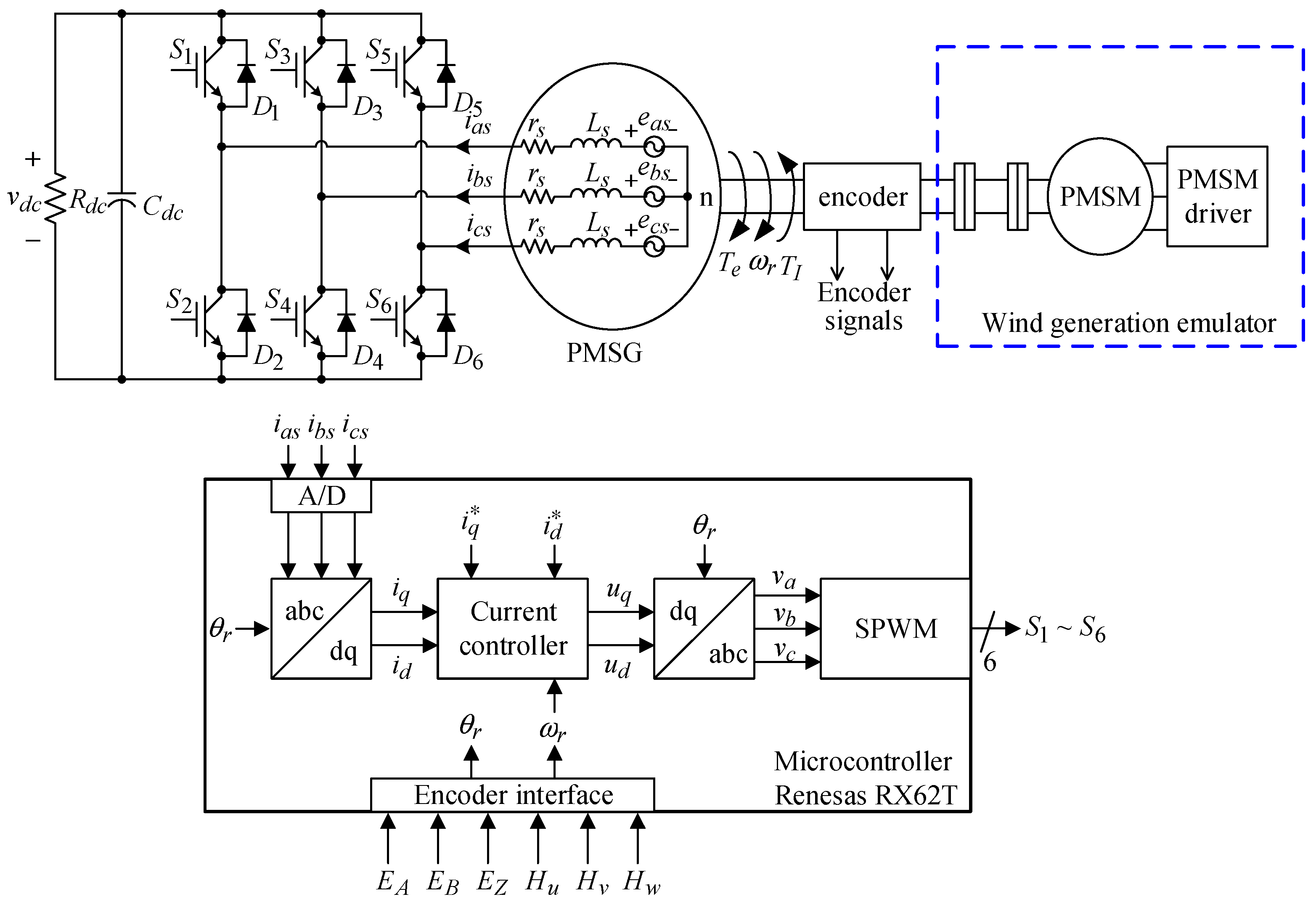
The system configuration of the PMSG drive is shown in Figure 1. The wind generation source is emulated by a PMSM with a PMSM driver. The required rotor speed and position are measured and calculated from the encoder. Three-phase winding currents of the PMSG are transformed to a rotor reference frame (dq-frame). The current controller based on T-S fuzzy models is implemented to generate the dq-frame voltage control efforts. The duty ratios of the power switches are determined by sinusoidal pulse-width modulation (SPWM).
The voltage equations of a PMSG in a dq-frame are [1]:
where vd and vq are dq-frame voltages, id and iq are dq-frame currents, rs is the winding resistance, Ld and Lq are dq-frame inductances, is the electrical rotor speed, and is the flux linkage established by the permanent magnet.
The electromagnetic torque produced by the PMSG is:
The mechanical equation of a PMSG is:
where J is the inertia of the PMSG, B is the damping coefficient of the PMSG, is the input torque, and P is the magnetic pole number.
To simplify the control scheme, the d-axis current is generally set at zero. Therefore, the electromagnetic torque of the PMSG can be directly controlled via tuning of the q-axis current. By assuming in (2), the state equations of the PMSG can be summarized as:
3. Design of the Current Controller
To ensure the current tracking error will converge to zero, two state variables are defined:
where is the target value of and is target value of .
New state equations of the PMSG can be obtained by combing (4) and (5):
where are the disturbances of the PMSG system.
The output of the PMSG is:
In the design of current controller, the nonlinear system is approximated by linear sub-systems according to the model rules of the T-S fuzzy models:
Model rules i: If is and … and is , then:
where is the fuzzy set, are the state variables, are the control inputs, and are the state matrices of the sub-system, and are selected as .
After defuzzification, the fuzzy system of the PMSG is:
where:
and is the grad of membership.
The parallel distributed compensation (PDC) controllers corresponding to the model rules are:
Control rules i: If is and … and is , then:
The close-loop system can be obtained by substituting (12) into (9):
The membership functions of are demonstrated in Figure 2a. and are the membership functions of the rule, i, is the minimum value of , and is the maximum value of . The membership functions can be represented as:
In the developed PMSG drive system, the range of is 0~18.5 A and the range of is 0~754 rad/s. By taking these values, the membership functions of are found:
For a particular value of , the grade of the membership function is first found as shown in Figure 2b. Then, the weightings of the membership functions are calculated:
The controller gain, , in (12) and the weightings, , in (18) are used to realize the close-loop current controller.
4. Stability Analysis
The current control of the PMSG drive based on T-S fuzzy models can be obtained from (7) and (8):
Define the performance index:
where is the ability of the disturbance suppression of the PMSG.
Lemma 1.
[24] Assume there exists a positive definite matrix, , which makes the following LMI condition to be feasible:
where:
Then, the designed current controller in (12) can ensure the tracking error converges to zero.
Proof.
Assume there exists a quadratic form function, , , and for all time, , then the LMI condition is:
By substituting (12) and (14) into (23):
By following the proper procedures proposed in [24], the LMI condition in (21) can be obtained from (24). By using the LMI condition in (21) and assuming , the following controller gains are obtained:
☐
5. Results and Discussions
Table 1 shows the parameters of the PMSG. The specifications of the PMSG drive are summarized in Table 2. The experimental setup of the developed PMSG system is shown in Figure 3. The implemented PMSG is model YBL17B-200L manufactured by YELI electric & machinery Co., Ltd., Taiwan. The oscilloscope is Agilent DSO-X 4024A (Agilent Technologies, Santa Clara, CA, USA). The current measurement system consists of the current probe Tektronix TCP303 and the amplifier Tektronix TCPA300.
5.1. Constant Current Command
The current command of the PMSG is set as , . The measured winding current waveforms at different generator speeds are shown in Figure 4a–c. The accuracy and total harmonic distortion (THD) of the current waveforms are summarized in Table 3. When the d-axis current is zero and the three-phase currents are balanced, the peak value of the three phase currents will be the q-axis current. From the experimental results, it is obvious that the desired peak value of the winding current is achieved at different generator speeds. The THD is also less than 2%, which means the three-phase currents are balanced. Since the three-phase currents are balanced and the desired peak value of the winding currents can be achieved, the output power of the PMSG can be controlled.
5.2. Variable Current Command
First, the current command is starting from zero to a constant value at 600 rpm. The winding current waveforms shown in Figure 5a,b verify the tracking capability of the current controller. The q-axis current accurately tracks the current command.
Next, the current command is variable from 0A→5A→10A→15A→10A→5A at 900 rpm and 1500 rpm. The winding current waveforms are shown in Figure 6a,b, respectively. From the experimental results, it can be found that the variable current command is well traced. Under this condition, the output power is variable and controllable by changing the current command.
6. Conclusions
A PMSG drive in wind generation systems was designed and implemented. The wind generation source was emulated via the PMSM with a PMSM driver. First, system configuration and dynamic models of a PMSG was illustrated. Next, the current controller was designed based on T-S fuzzy models. The design procedure of the T-S fuzzy current controller was introduced and the stability analysis was also presented. The design of the current controller and stability issues were simplified in the LMI. Moreover, the experimental setup was demonstrated. The performance of the current controller was verified by experimental results, including constant current command and variable current command. The output power of the PMSG can be varied and controlled via tuning the peak value of the three-phase balanced winding currents.
Author Contributions
The authors contributed equally to this work.
Funding
This research was supported by the Ministry of Science and Technology, Taiwan, under the Grant of MOST 107-2623-E-194-001-D.
Conflicts of Interest
The authors declare no conflict of interest.
References
- Krause, P.; Wasynczuk, O.; Sudhoff, S.D.; Pekarek, S. Analysis of Electric Machinery and Drive Systems, 3rd ed.; IEEE Press: Piscataway, NJ, USA, 2013; pp. 121–141. ISBN 978-1-118-02429-4. [Google Scholar]
- Yaramasu, V.; Wu, B. Predictive control of a three-level boost converter and an NPC inverter for high-power PMSG-based medium voltage wind energy conversion systems. IEEE Trans. Power Electron. 2014, 29, 5308–5322. [Google Scholar] [CrossRef]
- García-Gracia, M.; Cova, M.A.; Villen, M.T.; Uson, A. Novel modular and retractable permanent magnet motor/generator for flywheel applications with reduced iron losses in stand-by mode. IET Renew. Power Gener. 2014, 8, 551–557. [Google Scholar] [CrossRef]
- Hong, J.; Lee, H.; Nam, K. Charging method for the secondary battery in dual-inverter drive systems for electric vehicles. IEEE Trans. Power Electron. 2015, 30, 909–921. [Google Scholar] [CrossRef]
- Lai, Y.S.; Lee, W.T.; Lin, Y.K.; Tsai, J.F. Integrated inverter/converter circuit and control technique of motor drives with dual-mode control for EV/HEV Applications. IEEE Trans. Power Electron. 2014, 29, 1358–1365. [Google Scholar] [CrossRef]
- Lee, K.W.; Park, S.; Jeong, S. A seamless transition control of sensorless PMSM compressor drives for improving efficiency based on a dual-mode operation. IEEE Trans. Power Electron. 2015, 30, 1446–1456. [Google Scholar] [CrossRef]
- Jung, E.; Yoo, H.; Sul, S.K.; Choi, H.S.; Choi, Y.Y. A nine-phase permanent-magnet motor drive system for an ultrahigh-speed elevator. IEEE Trans. Ind. Appl. 2016, 48, 987–995. [Google Scholar] [CrossRef]
- Reddy, P.B.; El-Refaie, A.M.; Huh, K.K. Effect of number of layers on performance of fractional-slot concentrated-windings interior permanent magnet machines. IEEE Trans. Power Electron. 2015, 30, 2205–2218. [Google Scholar] [CrossRef]
- Do, T.D.; Kwak, S.; Choi, H.H.; Jung, J.-W. Suboptimal control scheme design for interior permanent-magnet synchronous motors: An SDRE-Based approach. IEEE Trans. Power Electron. 2014, 29, 3020–3031. [Google Scholar] [CrossRef]
- Pellegrino, G.; Vagati, A.; Guglielmi, P.; Boazzo, B. Performance comparison between surface-mounted and interior PM motor drives for electric vehicle applications. IEEE Trans. Ind. Electron. 2012, 59, 803–811. [Google Scholar] [CrossRef]
- Wang, Z.; Lu, K.; Blaabjerg, F. A simple startup strategy based on current regulation for back-EMF-based sensorless control of PMSM. IEEE Trans. Power Electron. 2012, 27, 3817–3825. [Google Scholar] [CrossRef]
- Jahns, T.M.; Soong, W.L. Pulsating torque minimization techniques for permanent magnet AC motor drives—A review. IEEE Trans. Ind. Electron. 1996, 43, 321–330. [Google Scholar] [CrossRef]
- Kim, K.C.; Lee, J.; Kim, H.J.; Koo, D.H. Multiobjective optimal design for interior permanent magnet synchronous motor. IEEE Trans. Magn. 2009, 45, 1780–1783. [Google Scholar] [CrossRef]
- Islam, R.; Husain, I.; Fardoun, A.; McLaughlin, K. Permanent-magnet synchronous motor magnet designs with skewing for torque tipple and cogging torque reduction. IEEE Trans. Ind. Appl. 2009, 45, 152–160. [Google Scholar] [CrossRef]
- Inoue, Y.; Morimoto, S.; Sanada, M. Control method suitable for direct-torque-control-based motor drive system satisfying voltage and current limitation. IEEE Trans. Ind. Appl. 2012, 48, 970–976. [Google Scholar] [CrossRef]
- Tseng, S.K.; Tseng, C.C.; Liu, T.H.; Chen, J.L. Wide-range adjustable speed control method for dual-motor drive system. IET Electr. Power Appl. 2015, 9, 107–116. [Google Scholar] [CrossRef]
- Domínguez, J.R.; Navarrete, A.; Meza, M.A.; Loukianov, A.G.; Canedo, J. Digital sliding-mode sensorless control for surface-mounted PMSM. IEEE Trans. Ind. Inform. 2014, 10, 137–151. [Google Scholar] [CrossRef]
- Chang, Y.C.; Wang, S.Y.; Dai, W.F.; Chang, H.F. Division-summation current control and one-cycle voltage regulation of the surface-mounted permanent-magnet synchronous generator. IEEE Trans. Power Electron. 2016, 31, 1391–1400. [Google Scholar] [CrossRef]
- Hwang, J.-C.; Wei, H.-T. The current harmonics elimination control strategy for six-leg three-phase permanent magnet synchronous motor drives. IEEE Trans. Power Electron. 2014, 29, 3032–3040. [Google Scholar] [CrossRef]
- Chou, M.C.; Liaw, C.M. Development of robust current 2-DOF controllers for a permanent magnet synchronous motor drive with reaction wheel load. IEEE Trans. Power Electron. 2009, 24, 1304–1320. [Google Scholar] [CrossRef]
- Uddin, M.N.; Radwan, T.S.; George, G.H.; Rahman, M.A. Performance of current controllers for VSI-fed IPMSM drive. IEEE Trans. Ind. Appl. 2000, 36, 1531–1538. [Google Scholar]
- Liaw, C.M.; Kang, B.J. A robust hysteresis current-controlled PWM inverter for linear PMSM driven magnetic suspended positioning system. IEEE Trans. Ind. Electron. 2001, 48, 956–967. [Google Scholar] [CrossRef]
- Weigold, J.; Braun, M. Predictive current control using identification of current ripple. IEEE Trans. Ind. Electron. 2008, 55, 4346–4353. [Google Scholar] [CrossRef]
- Chang, Y.C.; Chen, C.H.; Zhu, Z.C.; Huang, Y.W. Speed control of the surface-mounted permanent-magnet synchronous motor based on Takagi-Sugeno fuzzy models. IEEE Trans. Power Electron. 2016, 31, 6504–6510. [Google Scholar] [CrossRef]
- Wang, H.O.; Tanaka, K.; Griffin, M.F. An approach to fuzzy control of nonlinear systems: Stability and design issues. IEEE Trans. Fuzzy Syst. 1996, 4, 14–23. [Google Scholar] [CrossRef]
- Precup, R.-E.; Doboli, S.; Preitl, S. Stability analysis and development of a class of fuzzy control systems. Eng. Appl. Artif. Intell. 2000, 13, 237–247. [Google Scholar] [CrossRef]
- Skrjanc, I.; Blazic, S.; Matko, D. Direct fuzzy model-reference adaptive control. Int. J. Intell. Syst. 2002, 17, 943–963. [Google Scholar] [CrossRef]
- Vrkalovic, S.; Teban, T.-A.; Borlea, I.-D. Stable Takagi-Sugeno fuzzy control designed by optimization. Int. J. Artif. Intell. 2017, 15, 17–29. [Google Scholar]
Figure 1.
System configuration of the permanent-magnet synchronous generator (PMSG) drive.

Figure 2.
(a) Membership functions of and (b) grade of the membership function.

Figure 3.
Experimental setup of the developed PMSG drive.

Figure 4.
Measured winding current waveforms by setting = 15 A, = 0 A at different generator speeds: (a) 600 rpm; (b) 900 rpm; and (c) 1200 rpm.
Figure 4.
Measured winding current waveforms by setting = 15 A, = 0 A at different generator speeds: (a) 600 rpm; (b) 900 rpm; and (c) 1200 rpm.

Figure 5.
Measured winding current waveforms of the current command starts from zero to a constant value at 600 rpm: (a) 10 A and (b) 15 A.
Figure 5.
Measured winding current waveforms of the current command starts from zero to a constant value at 600 rpm: (a) 10 A and (b) 15 A.

Figure 6.
Measured winding current waveforms of the current command is variable from 0 A→5 A→10 A→15 A→10 A→5 A: (a) 900 rpm; (b) 1500 rpm.
Figure 6.
Measured winding current waveforms of the current command is variable from 0 A→5 A→10 A→15 A→10 A→5 A: (a) 900 rpm; (b) 1500 rpm.


Table 1.
Parameters of the permanent-magnet synchronous generator (PMSG).
| Poles | rs | Ld | Lq |
|---|---|---|---|
| 8 | 0.24 Ù | 1.896 mH | 2.131 mH |
| rated speed | rated torque | rated current | rated power |
| 1800 rpm | 23 N·m | 11.8 Arms | 4.5 kW |
Table 2.
Specifications of the PMSG Drive.
| rated power | 5 kW | DC-link voltage | 380 Vdc |
| rated voltage | 220 Vrms | DC-link capacitance | 5600 µF |
| rated current | 13.1 Arms | switching frequency | 20 kHz |
Table 3.
Accuracy and THD of the current waveforms.
| Generator Speed | Measured Current | Accuracy (%) | THD (%) |
|---|---|---|---|
| 600 rpm | 14.991 | 99.94 | 1.17 |
| 900 rpm | 14.849 | 98.99 | 1.38 |
| 1200 rpm | 14.944 | 99.63 | 1.16 |
Note: Accuracy (%) = , THD(%) = .
© 2018 by the authors. Licensee MDPI, Basel, Switzerland. This article is an open access article distributed under the terms and conditions of the Creative Commons Attribution (CC BY) license (http://creativecommons.org/licenses/by/4.0/).
Share and Cite
MDPI and ACS Style
Chang, Y.-C.; Chang, H.-C.; Huang, C.-Y. Design and Implementation of the Permanent- Magnet Synchronous Generator Drive in Wind Generation Systems. Energies 2018, 11, 1634. https://doi.org/10.3390/en11071634
AMA Style
Chang Y-C, Chang H-C, Huang C-Y. Design and Implementation of the Permanent- Magnet Synchronous Generator Drive in Wind Generation Systems. Energies. 2018; 11(7):1634. https://doi.org/10.3390/en11071634
Chicago/Turabian StyleChang, Yuan-Chih, Hao-Chin Chang, and Chien-Yu Huang. 2018. "Design and Implementation of the Permanent- Magnet Synchronous Generator Drive in Wind Generation Systems" Energies 11, no. 7: 1634. https://doi.org/10.3390/en11071634
Note that from the first issue of 2016, this journal uses article numbers instead of page numbers. See further details here.