Article

A Novel Triple-Permanent-Magnet-Excited Vernier Machine with Double-Stator Structure for Low-Speed and High-Torque Applications

1
School of Electrical and Information Engineering, Jiangsu University, Zhenjiang 212013, China
2
School of Electronics and Information, Jiangsu University of Science and Technology, Zhenjiang 212013, China
*
Author to whom correspondence should be addressed.
Energies 2018, 11(7), 1713; https://doi.org/10.3390/en11071713
Submission received: 23 May 2018 / Revised: 21 June 2018 / Accepted: 27 June 2018 / Published: 1 July 2018

Abstract

:
In this paper, a novel triple-permanent-magnet-excited vernier (TPMEV) machine with double-stator (DS) is proposed, of which the power density and the torque density are effectively improved to satisfy the operating requirements of low speed and high torque density for direct drive systems. Three sets of permanent magnets (PMs) are placed on the two stators and the rotor, respectively, and the magnetic fields excited by these PMs are modulated to effective magnetic field harmonics with low pole-pair numbers and high speeds based on bi-directional field modulation effect of the non-uniform airgap permeance. Then two sets of armature windings respectively accommodated in two stators are designed according to the effective magnetic field harmonics, thus achieving the coupling between the PM magnetic fields produced by three sets of PMs and armature windings. Firstly, the topology of the TPMEV-DS machine is introduced. Secondly, the airgap flux density of the machine is analyzed based on the equivalent magnetic circuit method, which proves the improvement potentiality of power density and torque density due to the bi-directional field modulation effect. Finally, the performance of the TPMEV-DS machine is calculated and analyzed by the finite element method, verifying the advantages of high power density and high torque density for the direct drive systems.

1. Introduction

Due to their low speed and high torque density performance, field-modulation (FM) permanent magnet (PM) machines, such as PM vernier machines [1,2], magnetic-geared PM machines [3,4], and vernier hybrid machines [5], have been widely used for direct drive applications. FMPM machines operate based on the field-modulation theory [6], in which the PM magnetic field is modulated by the non-uniform airgap permeance, so that a series of space harmonics with different pole-pair numbers and rotation speeds are generated in the airgap. Different from conventional PM machines, the armature windings of FMPM machines are connected according to one of the effective harmonic components with low pole-pair number and high speed. Thus, the rotation speed of armature reaction magnetic field is much higher than the rotor speed generally, so that the so called self-deceleration capability is realized [7,8], which can be expressed as
v a = v e f = N s t p a p a v t = p P M p a v t = G r v t
in which va and vef are the rotation speeds of the armature reaction magnetic field and the effective harmonic component, respectively; pa and Nst are the pole-pair number of armature windings and the number of modulating poles, respectively; pPM is the pole-pair number of PMs; Gr is named the magnetic gear ratio which is the rotation speed ratio between the armature reaction magnetic field and the rotor; and vt is the rotation speed of the rotor.
Then the torque output of an FMPM machine can be written as
T = μ A s B g m a x G r k d
in which µ is the coefficient relative to the machine structure, As is the stator electrical loading, Bgmax is the amplitude of the effective harmonic magnetic flux density and kd is the leakage coefficient.
It can be seen from (2) that the torque of FMPM machines is in proportion to the product of Bgmax and Gr when As and kd are determined. Thus, two methods can be adopted for the design of FMPM machines to further improve the torque density.
(a) Selecting a magnetic gear ratio as high as possible.
According to (1), Gr equals the ratio between pPM and pa, so the higher Gr can be obtained by increasing the pole-pair number of PMs or reducing the pole-pair number of armature windings [9,10].
(b) Increasing Bgmax.
Although high torque density performance can be achieved in FMPM machines based on its FM operating principle, the amplitude of effective magnetic field harmonics contributing to electromechanical energy conversion is much lower than that of conventional PM machines, so it is necessary to find an appropriate way to improve Bgmax [11,12].
However, the machine tooth-pole arrangement, especial the pole-pair of rotor PMs, is usually decided by the application requirements. Furthermore, the power factor may be reduced when the higher Gr is selected [13,14]. Thus, the torque density of FMPM machines can be improved by increasing the utilization ratio or consumption of PMs to increase Bgmax [15,16]. The armature windings of FMPM machines are connected according to the effective harmonic component of the magnetic field in the airgap rather than the fundamental one generated by PMs directly, so it is possible to obtain effective harmonics with same pole-pair number by modulated multiple sets of PMs with different pole-pair numbers according to (1). Thus, the resultant magnetic field Bgmax can be increased due to the contributions of each set of PMs. In [17], a dual-PM harmonic machine employing two sets of PMs located on stator and rotor, respectively, was proposed. The effective coupling between the magnetic field excited by these two sets of PMs and the armature windings is achieved by the so-called bi-directional field modulation effect. Thus, this dual-PMs harmonic machine has the capability to offer much higher torque owning to the utilization of two sets of PMs. According to the quantitative comparison between the dual-PMs machine and a conventional PM synchronous machine with the same rotor pole-pair number and overall dimension [18], the dual-PMs machine has a 125% higher torque output capability.
However, it is still desirable to find more effective methods for the further power density and torque density enhancement of FMPM machines because of the requirements of direct-drive systems. Actually, the operation principle of FMPM machines is similar to that of co-axial magnetic gears (MGs) and FMPM machines can be obtained from any co-axial MGs by replacing one set of PMs with armature windings [19] or just by adding armature windings directly on stators or rotors of co-axial MGs [20]. In [21], a triple-permanent-magnet-excited (TPME) MG was proposed and analyzed. Due to the adoption of a triple-permanent-magnet, the TPME MG can achieve a 20% higher torque density compared with conventional co-axial MGs, which provides a new design concept to increase the torque density of FMPM machines.
In this paper, a novel triple-permanent-magnet-excited vernier (TPMEV) machine with double-stator (TPMEV-DS) is proposed, which is composed of two coaxial stators and an intermediate rotor. Three sets of PMs are located on the double-stator (DS) and rotor, respectively. The adopted DS structure enables higher power and torque density due to the utilization improvement of the machine space. Furthermore, the bi-directional effects of the two airgaps are artfully engaged to guarantee the coupling between the effective harmonic magnetic fields excited by the three sets of PMs and the armature reaction magnetic field excited by the two sets of armature windings, so the power density and torque density are further improved. The detailed machine topology and operation principle will be discussed. Besides, two-dimensional finite element analysis (2D-FEA) will be used to calculate and analyze the machine performances.

2. Machine Configuration and Operation Principle

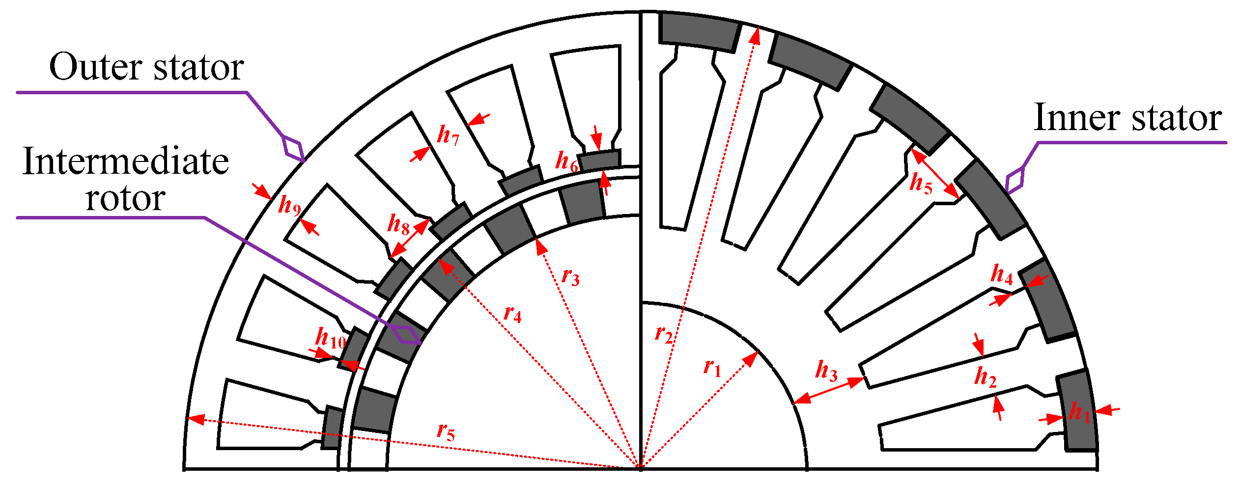
2.1. Machine Configuration

The structure of proposed TPMEV-DS machine is presented in Figure 1, in which the outer stator accommodating a set of three-phase windings, named “primary windings”, provides the main power of the machine. The other set of three-phase windings, named “secondary windings”, is accommodated in the inner stator. Two sets of PMs are mounted in the slot openings of outer stator and inner stator, respectively, while the intermediate rotor composed of segmented iron pieces and PMs are sandwiched between two stators. Based on the bi-directional field modulation effect of the two airgaps with non-uniform permeance, the magnetic fields excited by the three sets of PMs can be coupled with the fields produced by two sets of three-phase windings, which is helpful for the improvement of power density and torque density.
The TPMEV-DS machine operates on a field modulation effect, according to which the machine stator/rotor pole combination among stator teeth, PMs on stator, rotor teeth, PMs on rotor and the two sets of windings can be arranged. When the TPMEV-DS machine is excited only by PMs on DS, the stator/rotor pole combination is governed by
p P M s = p r ± p a
in which pa is the pole-pair numbers of primary windings and secondary windings, pPMs is the pole-pair numbers of PMs on each stator, and pr is the number of rotor teeth.
When the machine is excited only by PMs on the rotor, the stator/rotor pole combination is governed by
p P M r = p s p a
where ps is the number of stator teeth, pPMr is the pole-pair number of PMs on rotor.
The stator/rotor pole combination adopted by the TPMEV-DS machine in this paper is
p a = 2
p s = p P M s = 24
p r = p P M r = 22

2.2. Operation Principle

According to (3) and (4), the TPMEV-DS machine can be divided into two parts according to the different excitations of PMs. Figure 2 shows the magnetic field distributions due to the different excitations of PMs. The segmented iron pieces of the rotor and the salient teeth of DS lead to the non-uniform airgap permeance, thus a number of asynchronous space harmonics can be produced. When the machine is excited only by PMs on DS, the stationary magnetic field with 24 pair pole-pair numbers is modulated by the rotating 22 rotor teeth, and the effective harmonic magnetic field with 2 pole-pair numbers is generated in two airgaps, as shown in Figure 2a. Simultaneously, the rotating magnetic field with 22 pole-pair numbers excited by PMs on the rotor is modulated by 24 stationary teeth of two stators, respectively, then the effective harmonic magnetic field with 2 pole-pair numbers is achieved in two airgaps as shown in Figure 2b. Comparing Figure 2a,b, the magnetic field distributions and flux linked by two sets of windings are consistent. So the PMs respectively located on the stators and rotor can contribute to the energy conversion together. In Figure 2c, the magnetic field is excited by three sets of PMs together, which is equivalent to the superposition of magnetic fields excited by DS PMs and rotor PMs. Compared with the conventional FMPM machines, the amount of PMs is increased, so the airgap flux density as well as power density and torque density can be improved.

2.3. Harmonic Analysis

To more clearly reveal the operation principle and torque generation mechanism of the TPMEV-DS machine, the flux density in the airgap is analyzed based on the equivalent magnetic circuit method. Some assumptions are made to simplify the process of analysis.
The relative permeability of PM is 1.
The magnetic field changes only in a radial direction.
Ignore the magnetic saturation in iron cores.
Ignore the magnetic leakage.
All the PMs are uniformly arranged in the outer stator slots, and each PM and its adjacent outer stator tooth constitutes a pair of magnetic poles. When only PMs on the out stator are considered, the corresponding PM magnetomotive force (MMF) can be expressed as
F P M s _ o u t ( θ ) = m = 1 , 3 + 2 F P M s _ o u t m π sin ( m p P M s θ P M s 2 ) cos ( m p P M s θ )
where the FPMs_out is the MMF amplitude of a single PM pole, pPMs is the pole number of the PMs and the θPMs is the arc of outer stator PMs.
The intermediate rotor is composed of segmented iron pieces and PMs. Because of the different permeance of PMs and segmented iron, a non-uniform airgap is established. Considering the rotation of the rotor, the rotor permeance can be expressed as
λ r ( θ , t ) = λ r 0 + n = 1 + 2 λ p p r n π sin ( n p r θ r 2 ) cos [ n p r ( θ θ 0 ω r t ) ]
where λr0 and λppr are the average value and peak-to-peak value of the rotor permeance, respectively, pr is the number of rotor iron poles, θr is the arc of single rotor iron pole, θ0 and ωr are the initial mechanical angle and the mechanical angular velocity of the rotor.
Thus, according to (8) and (9), the flux density in the inner airgap can be expressed as
{ B ( θ , t ) = F P M s _ o u t ( θ ) λ r ( θ , t ) = A 1 n = 1 , 3 , 5 + ε 1 cos ( m p P M s θ ) + A 2 n = 1 , 3 + m = 1 + ε 1 ε 2 [ cos α 1 + cos α 2 ] A 1 = 2 λ r 0 p P M s _ o u t F P M s π ,   A 2 = 2 λ p p r p P M s F P M s _ o u t π 2 ε 1 = 1 m sin ( m p P M s θ P M s 2 ) ,   ε 2 = 1 n sin ( n p r θ r 2 ) α 1 = ( m p P M s + n p r ) [ θ n p r ( θ 0 + ω r t ) m p P M s + n p r ] α 2 = ( m p P M s n p r ) [ θ + n p r ( θ 0 + ω r t ) m p P M s n p r ]
From (10), it can be found that the airgap flux density has both stationary and rotating components, and the spatial orders, amplitudes and rotational velocities of the corresponding harmonics in the inner airgap are summarized in Table 1. At the same time, the flux density harmonics are also generated in the outer airgap, of which the spatial order and the rotation velocities are consistent theoretically with those in the inner airgap; however, the amplitudes are different. It should be mentioned that the flux density produced by the PMs on the inner stator and its corresponding harmonic analysis are similar to those due to the PMs on outer stator, so it is not presented in this paper.
Secondly, all the PMs are uniformly arranged between the adjacent segmented irons on the rotor. Each PM and its neighboring iron core constitute a pair of magnetic poles. Taking the rotation of the rotor into account, the corresponding MMF produced by the PMs on the rotor can be indicated as:
F P M r ( θ , t ) = i = 1 , 3 + 2 p P M r F P M r i π sin ( i p P M r θ P M r 2 ) cos [ i p P M r ( θ θ 0 ω r t ) ]
where FPMr is the MMF amplitude of a single PM pole, pPMr is the pole-pair number of rotor PM magnetic fields, and θPMr is the PM arc.
To the magnetic field produced by the rotor PMs, the teeth of two stators function as modulation poles, and the modulation functions of the outer and inner stators are similar to generate flux density harmonics in outer airgap and inner airgap, respectively. Thus, only the modulation function of inner stator teeth is presented. The inner stator permeance can be expressed as
λ s _ i n n e r ( θ ) = λ 0 _ i n n e r + j = 1 + 2 λ p p s j π sin ( j p s θ s _ i n n e r 2 ) cos ( j p s θ )
where the λ0_inner and the λpps are the average value and the peak-to-peak value of inner stator permeance, and θs_inner is the arc of stator teeth.
So the harmonics in the inner airgap can be expressed as
{ B ( θ , t ) = F P M r ( θ , t ) λ s _ i n n e r ( θ ) = A 3 i = 1 , 3 + ε 3 cos [ i p P M r ( θ θ 0 ω r t ) ] + A 4 i = 1 , 3 , 5 + j = 1 + ε 3 ε 4 [ cos α 3 + cos α 4 ] A 3 = 2 λ 0 _ i n n e r p P M r F P M r π ,   A 4 = 2 λ p p s p P M r F P M r π 2 ε 3 = 1 i sin ( i p P M r θ P M r 2 ) ,   ε 4 = 1 j sin ( j p s θ s _ i n n e r 2 ) α 3 = ( j p s + i p P M r ) [ θ i p P M r ( θ 0 + ω r t ) j p s + i p P M r ] α 4 = ( j p s i p P M r ) [ θ + i p P M r ( θ 0 + ω r t ) j p s i p P M r ]
The spatial orders, amplitudes and rotational velocities of the corresponding harmonics in inner airgap are summarized in Table 2.
From Table 1 and Table 2, it can be seen that a series of harmonics are produced by modulating the magnetic fields excited by the PMs on the DS and rotor, respectively. In Table 1, there are three kinds of main harmonics, which can be divided into stationary and rotating components. The harmonics of group 1 are stationary and are produced by PMs on the stator without modulation. The harmonics of group 2 and group 3 are the components produced by the modulation of rotor iron poles to the magnetic field of group 1. In Table 2, the harmonics of group 1 are directly excited by the PMs on the rotor which rotates synchronously with the rotor. The harmonics of group 2 and group 3 are generated by the modulation of stator teeth to the components of group 1.
Furthermore, the speed of the harmonic components of group 1 in Table 1 is 0; therefore, it cannot induce back electromotive force (EMF) in two sets of windings and no energy conversion is achieved. The harmonic components of group 1 in Table 2 is directly excited by rotor PMs and synchronously rotates with the rotor, which are used to achieve energy conversion in conventional PM machines. The harmonic components of group 2 and group 3 in Table 1 and Table 2, respectively, have the same pole-pair numbers and speeds, so they can contribute to produce torque output together when the magnetic fields of two sets of armature windings have the same spatial order and rotating speed. In order to achieve the low speed and high torque performances, the armature windings is designed according to the effective harmonic component with the lowest pole-pair number and the highest rotating speed. So the harmonic components of group 2 in Table 1 and Table 2 are selected and the pole-pair number of the effective harmonic is 2 with m = n = i = j = 1.
On the other hand, in order to achieve effective coupling between the armature magnetic field and the effective PM harmonic magnetic field, the frequency of current injected into the armature windings is obtained as
f a = p e f s ω e f s 2 π = p e f r ω e f r 2 π = p r ω r 2 π
where the pefs and ωefs are the pole-pair number of effective harmonics excited by PMs on the stator and its corresponding mechanical angular speed, respectively; and pefr and ωefr are the pole-pair number of the effective harmonic excited by PMs on rotor and its corresponding mechanical angular velocity, respectively. It can be seen that the rotational speed of armature reaction magnetic field is different from the rotating speed of the rotor, but the frequency of armature current is the same with traditional PM synchronous machines.

3. Performance Analysis

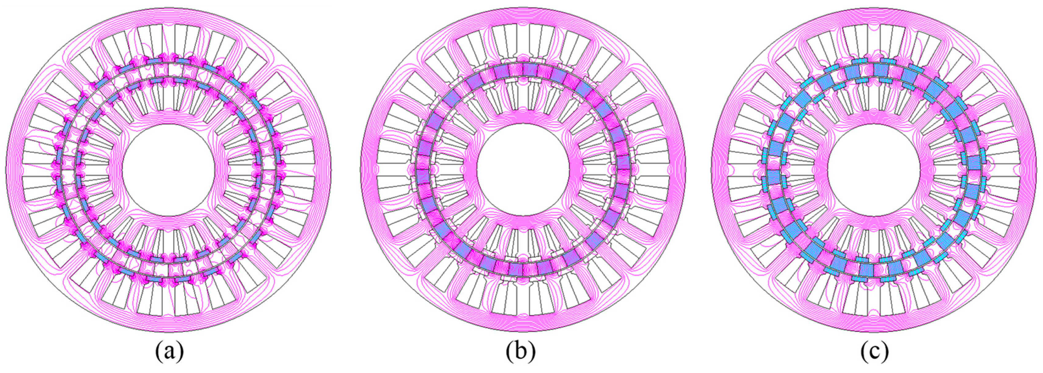
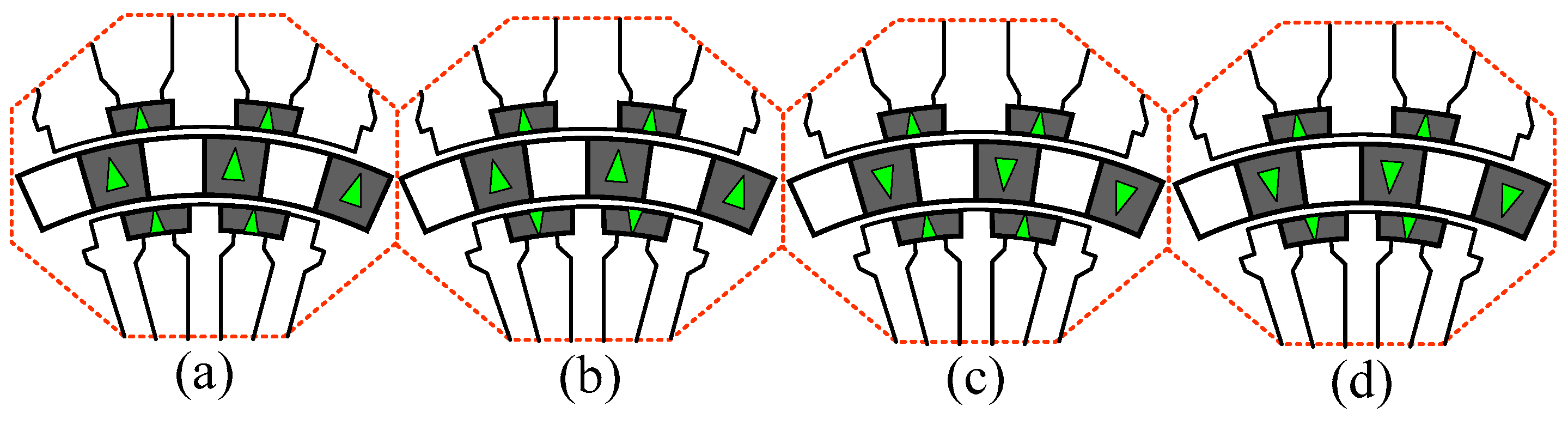
3.1. Magnetization Patterns

The TPMEV-DS machine possesses three sets of PMs. According to (10) and (13), the TPMEV-DS machine can operate when these PMs are magnetized in different directions, namely the radial outward direction or radial inward direction, respectively. Thus, four possible magnetization patterns can be achieved, as shown in Figure 3. Dimension parameters are defined in Figure 4 and listed in Table 3.
Back-EMF waveforms of the phase A in four models with different magnetization patterns are shown in Figure 5. Compared Figure 5a,b, it can be seen that the maximum peak value is achieved when the magnetization directions of the three sets of PMs are same, as shown in Model 1, so the magnetization pattern of Model 1 is adopted in this paper.

3.2. Relative Position of Inner Stator and Outer Stator

The TPMEV-DS machine adopts a coaxial double stator, and the magnetic circuit may be changed with the change of relative position of inner stator and outer stator. The electrical angle between the centerlines of outer stator teeth and inner stator teeth is defined as β, as shown in Figure 6. Figure 7 shows the magnetic field distributions when β = 0°, β = 60°, β = 120° and β = 180°. It can be seen that shorted magnetic flux around airgaps by the stators’ teeth and rotor iron cores is increased with the improvement of β, and the magnetic flux coupled by the armature windings is decreased as well, which can be seen from the reduced magnetic field density in the outer stator yoke. Thus, the maximum back-EMF is obtained under β = 0°. Figure 8 shows the variation trend of back-EMF peak values inducted in two sets of windings and the peak-to-peak value of cogging torque versus the changes of β, respectively. It can be seen that the back-EMF peak values of the two sets of windings reach the maximum values and the peak-to-peak value of cogging torque is relatively small when β equals zero, respectively. So β is selected to be zero in this paper.

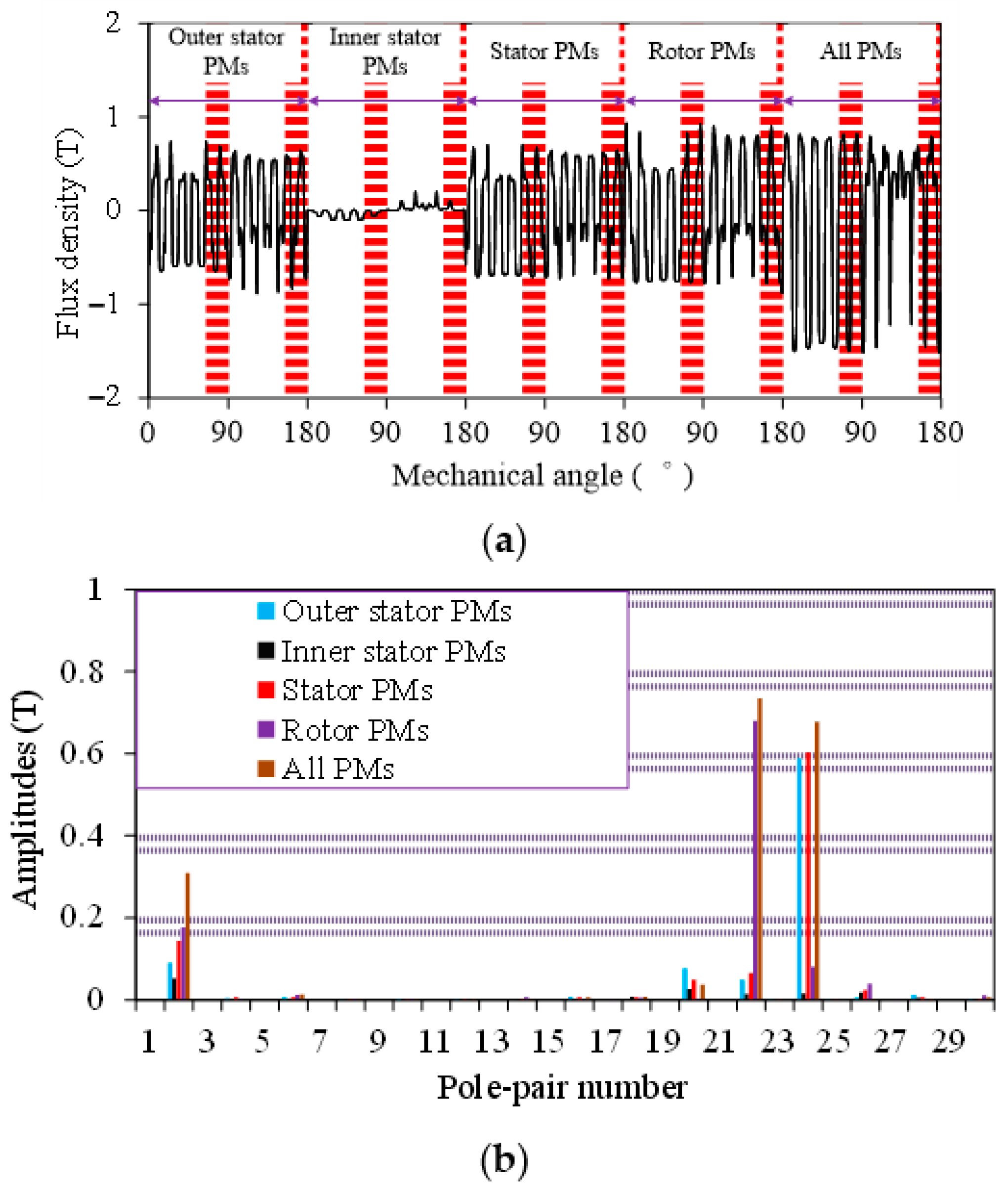
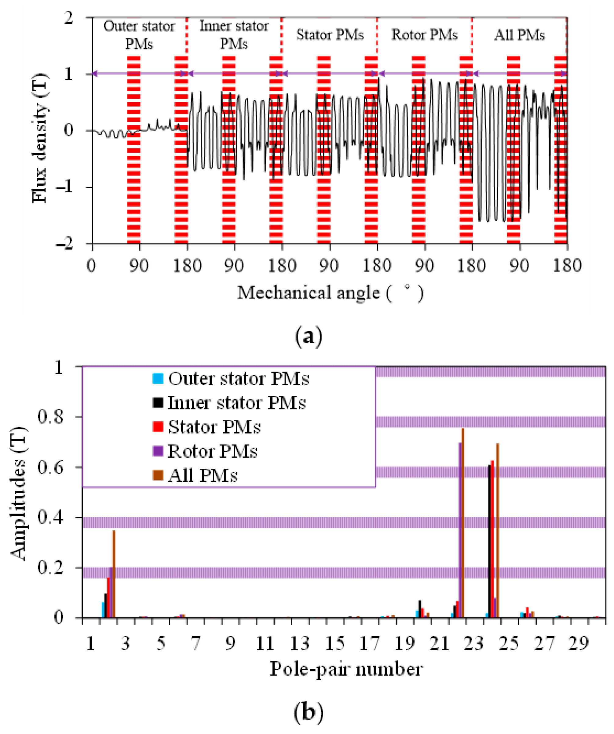
3.3. Airgap Flux Density

In order to verify the harmonic analysis in Section 2.3, the airgap flux density in the outer airgap and inner airgap are calculated by FEA. Figure 9 shows the airgap density waveforms in the outer airgap in 0 to 180 mechanical degrees due to different excitation sources and the corresponding harmonic spectra. The amplitudes of the main harmonics are listed in Table 4. Firstly, the main harmonics of the airgap flux density due to outer stator PMs and inner stator PMs are, respectively, the 2nd and the 24th components, where the 24th harmonic component is directly excited by PMs with 24 pole-pair number and the 2nd harmonic component is generated by modulation of segmented iron cores of the intermediate rotor. When the machine is excited by PMs on the rotor, the main harmonics in the outer airgap are the 22nd and the 2nd components, where the 22nd harmonic is directly excited by rotor PMs whilst the 2nd harmonic component is generated by the modulation of the outer stator teeth. So, the primary windings are designed according to the 2nd harmonic component to couple with three sets of PMs together. It can be seen that the amplitude of the resultant 2nd harmonic component excited by the three sets of PMs is 0.309T, which is almost the sum of the 2nd harmonic components respectively excited by the three sets of PMs.
The airgap flux density waveforms in the inner airgap excited by different excitation sources and corresponding harmonic spectra are shown in Figure 10. The amplitudes of the main harmonics in the inner airgap are listed in Table 5. It can be seen that the modulation functions of the stator teeth and rotor segmented iron cores to the airgap flux density due to different PM arrays are similar to those presented in Figure 9, namely all of the flux density in the inner airgap due to the three sets of PMs contain the 2nd harmonic component. So the secondary winding can be connected with 2 pole-pair numbers. Furthermore, the 2nd harmonic amplitude is 0.348T, which is close to the sum of the 2nd harmonic components respectively excited by different PMs.

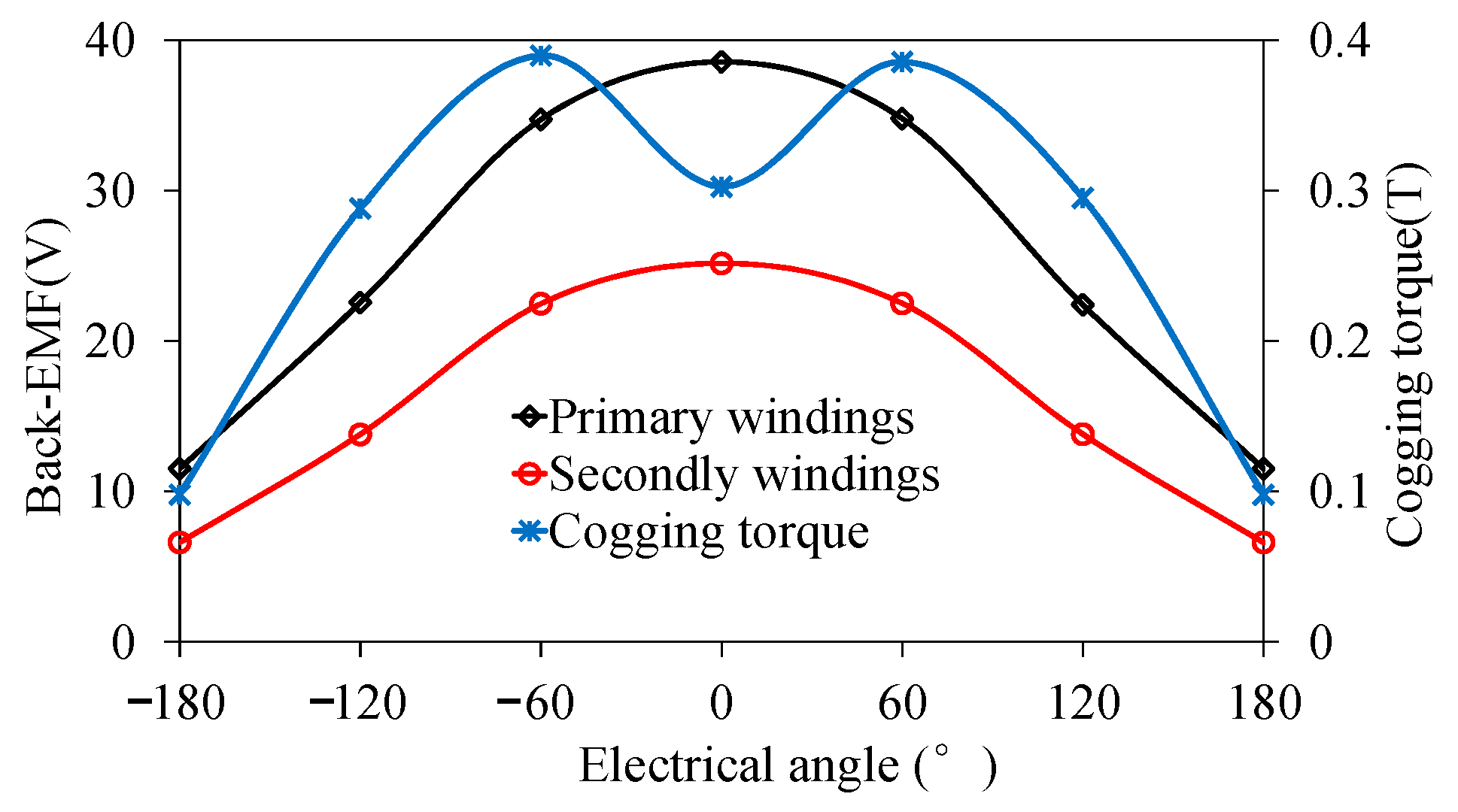
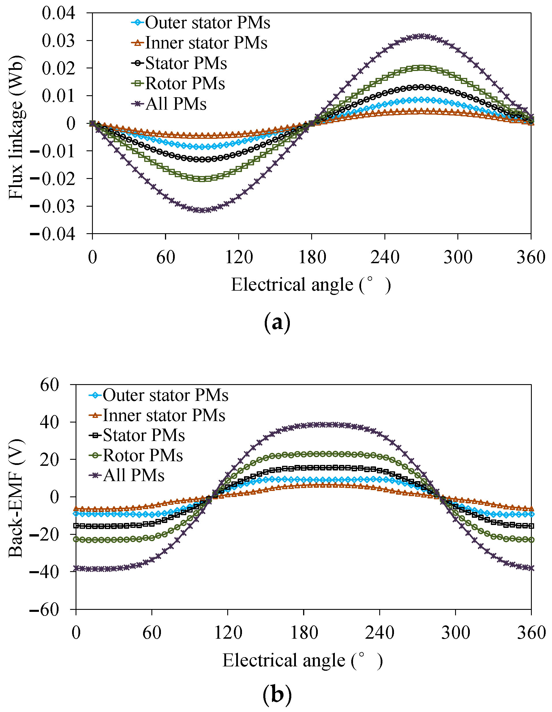
3.4. Flux Linkage and No-Load Back-Electromotive Force (EMF)
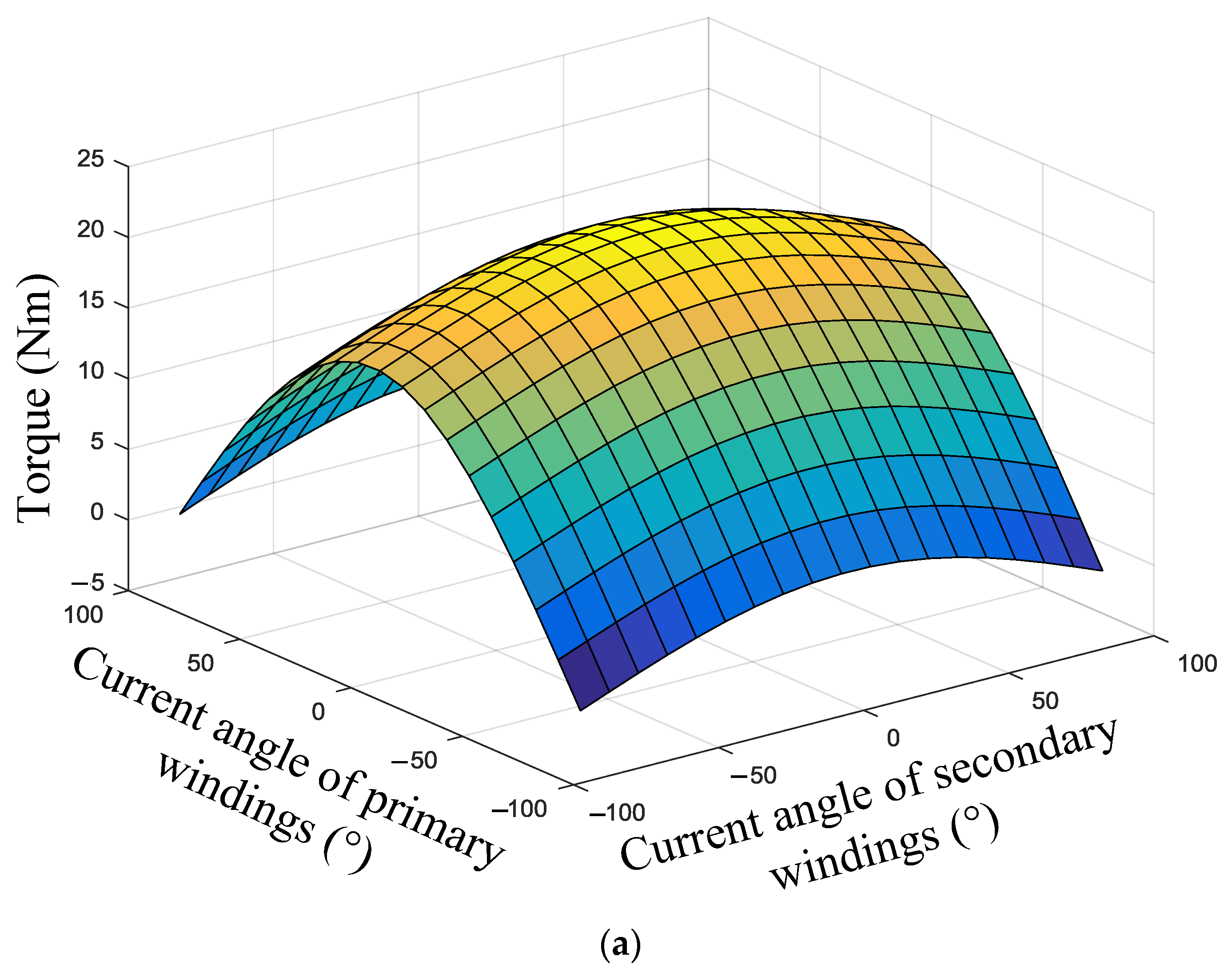
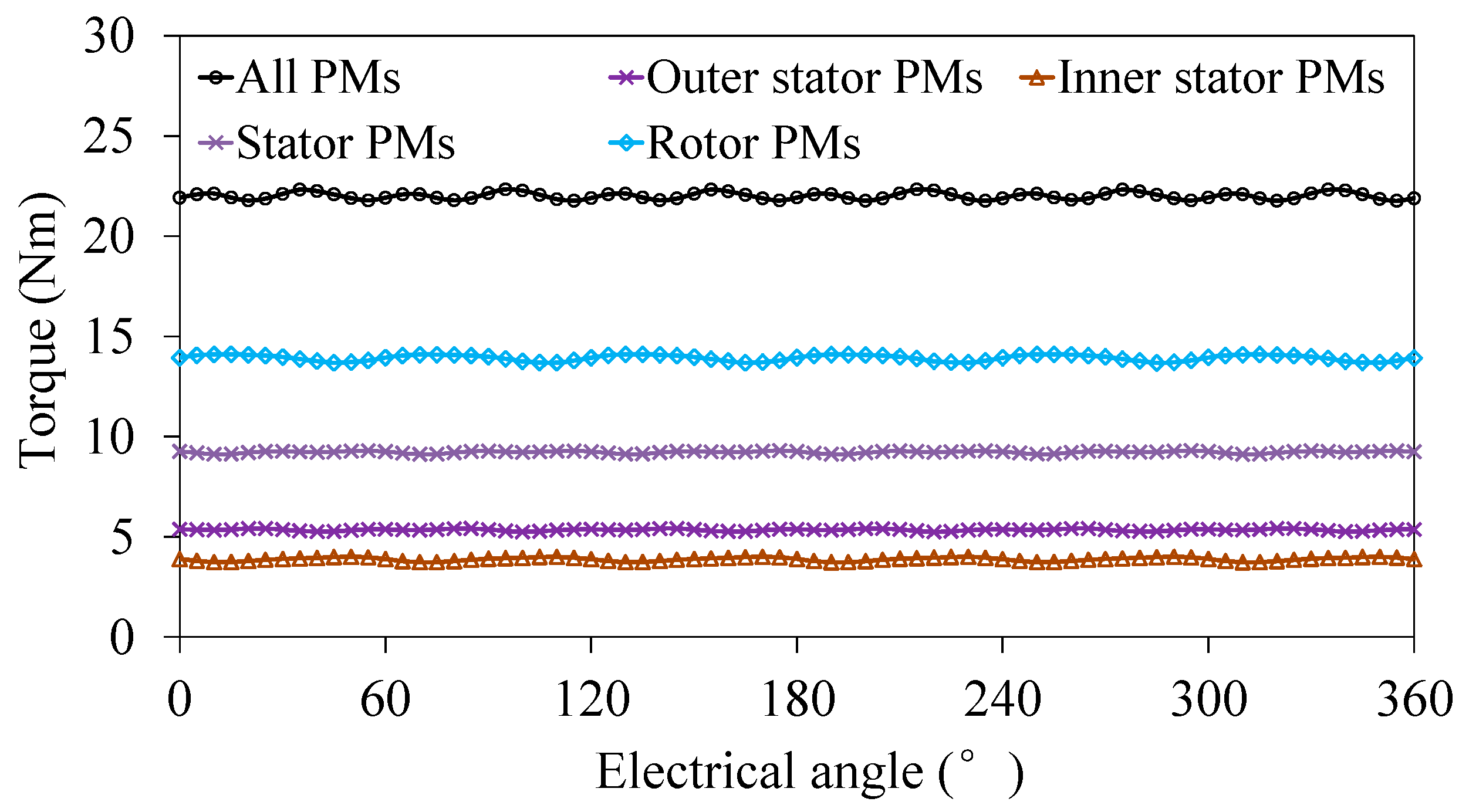
Figure 11a shows flux linkage waveforms in the primary windings due to different excitation sources, and the corresponding back-EMF waveforms are presented in Figure 11b. It can be seen that the phases of flux linage and back-EMF waveforms due to different excitation sources are the same, so it can be concluded that the three sets of PMs play a positive role for energy conversion.
Firstly, when PMs on the two stators are excited, the peak values of flux linkage in primary windings excited by outer stator PMs and inner stator PMs are 0.0086 Wb and 0.0045 Wb, respectively, and its corresponding back-EMF are 9.57 V and 6.48 V, respectively. According to the analysis of airgap flux density in part 3.3, the flux linkage and the back-EMF excited by two sets of PMs on the stator can be calculated as
{ ψ s = ψ s _ o u t e r + ψ s _ i n n e r E s = E s _ o u t e r + E s _ i n n e r
where ψs_outer and ψs_inner are the flux linkage excited by PMs on the outer stator and inner stator, respectively, and the Es_outer and Es_inner are the corresponding back-EMF, respectively.
It can be seen that the theoretical peak values of flux linkage and back-EMF in the primary windings due to two sets of stator PMs are 0.0131 Wb and 16.05 V, which are almost the same as the FEA results of 0.0131 Wb and 15.71 V, respectively. Besides, the peak values of the flux linkage and back-EMF excited by the PMs on the rotor are 0.0201 Wb and 23.03V, respectively. Thus, when the machine is excited by three sets of PMs, the flux linkage and the back-EMF can be calculated as
{ ψ a = ψ s + ψ r E a = E s + E r
where ψr and Er are the flux linkage and the back EMF excited by the PMs on rotor, respectively.
It can be seen that the theoretical peak values of total flux linkage and total back-EMF in the primary windings are 0.0332 Wb and 39.08 V, which agree well with the FEA results of 0.0315 Wb and 38.59 V, as shown in Figure 10b.
Similarly, the flux linkage and the back-EMF in the secondary windings can be calculated and analyzed. As shown in Figure 12, when the machine is respectively excited by outer and inner stator PMs, rotor PMs and all of the three sets of PMs, the peak values of flux linkage and back-EMF are 0.0031 Wb and 4.27 V, 0.0052 Wb and 6 V, 0.0128 Wb and 14.98 V, and 0.02 Wb and 25.17 V, respectively, which also agrees well with the results obtained from (15) and (16).
From the analysis of flux linkage and back-EMF of the primary and secondary windings, it can be seen that the two sets of windings can couple with the three sets of PMs on the stator and rotor simultaneously, which is consistent with the analysis of airgap flux density in part 3.3. Thus, the back-EMF and the power density can be improved effectively compared with those of existing machines with single-layer and double-layer PMs.

3.5. Torque

In order to obtain the optimum current phase angle for the maximum output torque, the torque against current angle characteristics are calculated. As shown in Figure 13a, the maximum electromagnetic torque can be obtained when the current angle equals zero in both armature windings. Furthermore, the electromagnetic torque waveforms due to different excitation sources are shown in Figure 13b with different current angles. It can be seen again that the maximum electromagnetic torque is obtained when the current angles of primary windings and secondary windings both equal zero. Thus, the id = 0 control method is adopted to obtained the high torque current ratio. The magnetic performances of stator PM motor and rotor PM motor is analyzed and compared in [22], which indicated that the PM utilization ratio with PMs mounted in the stator is significantly lower than that with PMs in the rotor. Furthermore, it can be seen from Table 3 that the volume of the three sets of PMs are different, namely, the volume of outer stator PMs and inner stator PMs are 16,400 mm2 and 13,900 mm2, respectively, whilst the volume of rotor PMs is 37,350 mm2. So, the rotor PMs provide the maximum torque and the inner stator provides the minimum torque, as depicted in Figure 14.
Figure 14 shows the average torque waveforms versus different excitation sources with same slot current density of 6 A/mm2 in the outer stator and 5 A/mm2 in the inner stator. Ignoring the iron core saturation, the amplitude of torque is linear with the peak value of flux linkage and the q-axis current in armature windings. According to the analysis of flux linkage and back-EMF, the torque can be expressed as
{ T s = T s _ o u t e r + T s _ i n n e r T e m = T s + T r
where Ts_outer and Ts_inner are the torque generated by PMs on the outer stator and inner stator, respectively, Ts and Tr are the torque generated by two sets of PMs on the stator and the PMs on the rotor.
It can be seen that the average values of the torque are 5.346 Nm and 3.88 Nm when the machine is excited by the outer stator and inner stator PMs, respectively. Besides, the average value of torque excited by two stator PMs is 9.226 Nm according to (17), which is consistent with the simulation value of 9.225 Nm. Moreover, the average value of torque due to the rotor PMs is 13.926 Nm, so the resultant torque can be calculated to be 23.152 Nm according to (17), which agrees well with the FEA result of 22.01 Nm.
Figure 15 shows the torque-current characteristics under different slot current density. It can be seen that the average torque increases linearly with the slot current density, which indicates that the machine has a desirable overload capability.

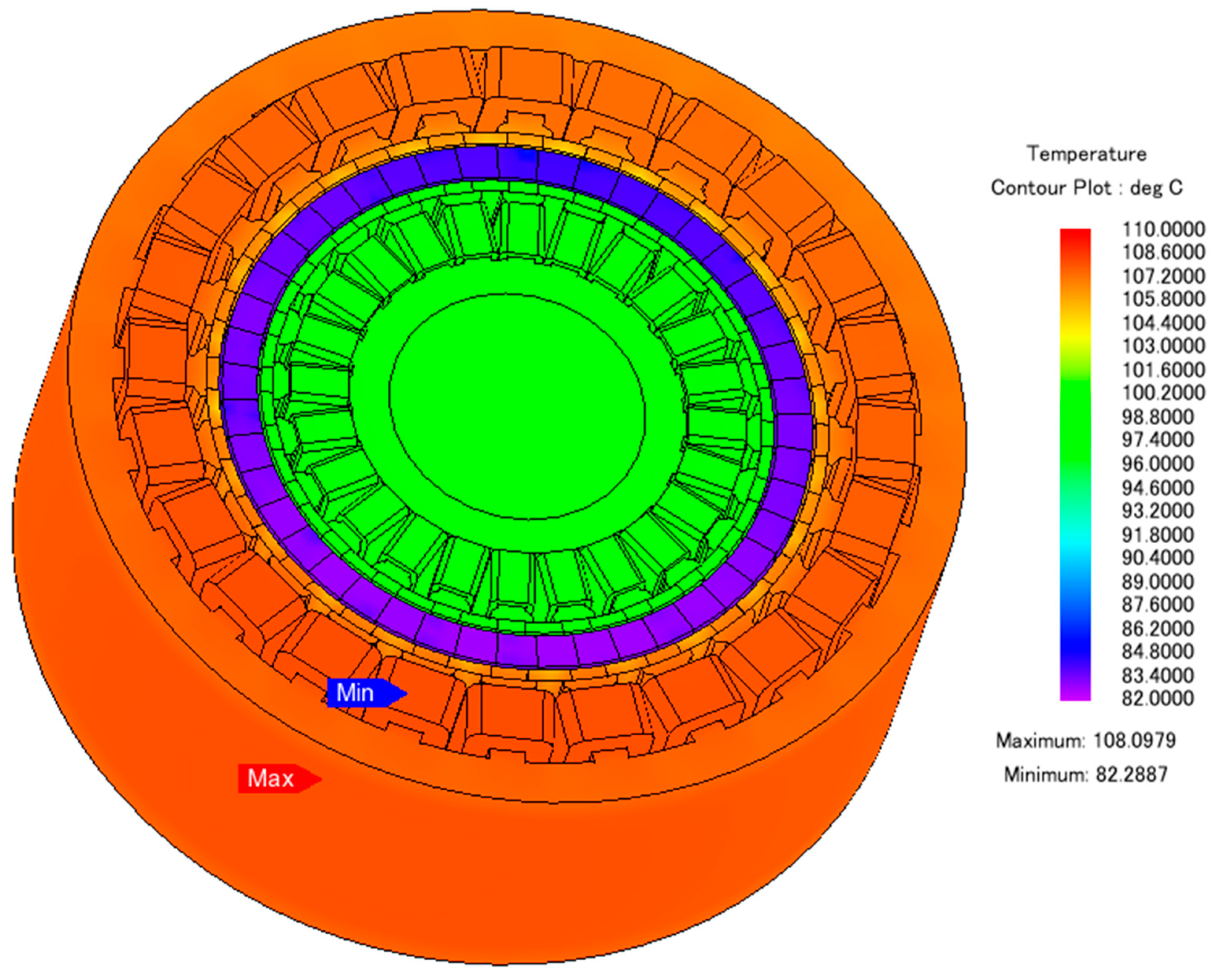
3.6. Temperature Field Analysis

Figure 16 shows the temperature field distribution of the proposed TPMEV-DS machine under the rated conditions at 7200 s. Due to the copper loss of primary windings being much higher than that of secondary windings, the outer stator exhibits higher temperature compared with the inner stator. Figure 17 shows the corresponding temperature curves. It can be seen that the steady temperatures of the primary windings, secondary windings, inner stator PMs, rotor stator PMs and outer stator PMs are 107 °C, 99.9 °C, 99.4 °C, 83.1 °C and 106.5 °C, respectively.

4. Conclusions

In this paper, a novel TPMEV-DS machine is proposed, in which the DS and intermediate rotor structure are adopted and three sets of PMs are located on the DS and rotor of the machine, respectively. The DS teeth and segmented iron of the rotor lead to non-even airgap magnetic reluctance for magnetic fields produced by three sets of PMs, and thus a series of field harmonic components can be produced in the two airgaps based on the modulation effect. By selecting a suitable stator/rotor pole combination, all of the flux density in the outer airgap and inner airgap due to three sets of PMs contain the 2nd harmonic component, so two sets of windings are connected according to this effective harmonic component in order to achieve the coupling with three sets of PMs simultaneously, and thus the performance of low-speed and high-torque can be performed. Based on the equivalent magnetic circuit method, the operation of the machine is analyzed. Furthermore, the static characteristics such as flux density and corresponding harmonic spectra, flux linkage and torque are analyzed by 2D-FEA to verifying the theory. This confirms that the torque of the proposed machine can be improved due to the adoption of the triple-permanent-magnet structure. Finally, thermal behavior is analyzed which shows the machine can run safely.

Author Contributions

X.L. is the main author of this manuscript. X.Z. is the main author of this manuscript who conceived of the idea of the research and implemented the research. Y.D. provided guidance and supervision. X.C. provided some useful suggestions in the construction of this paper. All the authors have contributed significantly to this work.

Acknowledgments

This work was supported in part by the National Natural Science Foundation of China under Project 51677081 and 51777089, in part by the grant from the Priority Academic Program Development of Jiangsu Higher Education Institution, in part by the Fund Program of Jiangsu University for Excellent Youth Teachers, and in part by Jiangsu University under Project 14JDG169. We also thank Deming Wang from Nanjing Tech University for the contribution to the improvement of English expression and organization.

Conflicts of Interest

The authors declare no conflict of interest.

References

  1. Li, X.L.; Chau, K.T.; Cheng, M. Analysis, design and experimental verification of a field-modulated permanent-magnet machine for direct-drive wind turbines. IET Electr. Power Appl. 2015, 9, 150–159. [Google Scholar] [CrossRef]
  2. Zhao, W.X.; Zheng, J.Q.; Wang, J.B.; Liu, G.H.; Zhao, J.X.; Fang, Z.Y. Design and analysis of a linear permanent-magnet vernier machine with improved force density. IEEE Trans. Ind. Electron. 2015, 63, 2072–2082. [Google Scholar] [CrossRef]
  3. Jian, L.N.; Chau, K.T.; Jiang, J.Z. A magnetic-geared outer-rotor permanent-magnet brushless machine for wind power generation. IEEE Trans. Ind. Appl. 2009, 45, 954–962. [Google Scholar] [CrossRef]
  4. Wang, L.L.; Shen, J.X.; Luk, P.C.; Fei, W.Z.; Wang, C.F.; Hao, H. Development of a magnetic-geared permanent-magnet brushless motor. IEEE Trans. Magn. 2009, 45, 4578–4581. [Google Scholar] [CrossRef] [Green Version]
  5. Du, Y.; Cheng, M.; Chau, K.T.; Liu, X.X.; Xiao, F.; Zhao, W.X.; Shi, K.; Mo, L.H. Comparison of linear primary permanent magnet vernier machine and linear vernier hybrid machine. IEEE Trans. Magn. 2014, 50, 8202604. [Google Scholar] [CrossRef]
  6. Cheng, M.; Han, P.; Hua, W. A general airgap field modulation theory for electrical machines. IEEE Trans. Ind. Electron. 2017, 64, 6063–6074. [Google Scholar] [CrossRef]
  7. Jian, L.; Xu, G.; Mi, C.C.; Chau, K.T.; Chau, C.C. Analytical method for magnetic field calculation in a low-speed permanent-magnet harmonic machine. IEEE Trans. Energy Convers. 2011, 26, 862–870. [Google Scholar] [CrossRef] [Green Version]
  8. Salihu Mustafa, S.; Misron, N.; Mariun, N.; Othman, M.L.; Hanamoto, T. Torque distribution characteristics of a novel double-stator permanent magnet generator integrated with a magnetic gear. Energies 2017, 10, 2. [Google Scholar] [CrossRef]
  9. Du, Y.; Zhang, C.; Zhu, X.Y.; Xiao, F.; Sun, Y.; Zuo, Y.; Quan, L. Principle and analysis of doubly salient PM motor with П-shaped stator iron core segments. IEEE Trans. Ind. Electron. 2018. [Google Scholar] [CrossRef]
  10. Du, Y.; Xiao, F.; Hua, W.; Zhu, X.Y.; Cheng, M.; Quan, L.; Chau, K.T. Comparison of flux-switching PM motors with different winding configurations using magnetic gearing principle. IEEE Trans. Magn. 2016, 52, 8201980. [Google Scholar] [CrossRef]
  11. Zhu, X.Y.; Shu, Z.M.; Quan, L.; Xiang, Z.X.; Pan, X.Q. Design and multi-condition comparison of two outer-rotor flux-switching permanent magnet motors for in-wheel traction applications. IEEE Trans. Ind. Electron. 2017, 64, 6137–6148. [Google Scholar] [CrossRef]
  12. Zhu, X.Y.; Xiang, Z.X.; Quan, L.; Wu, W.Y.; Du, Y. Multi-Mode optimization design methodology for a flux-controllable stator permanent magnet memory motor considering driving cycles. IEEE Trans. Ind. Electron. 2018, 65, 5353–5366. [Google Scholar] [CrossRef]
  13. Wang, S.Y.; Zhao, W.X.; Ji, J.H.; Xu, L.; Zheng, J.Q. Magnetic gear ratio effects on performances of linear primary permanent magnet vernier motor. IEEE Trans. Appl. Supercond. 2016, 26, 0610505. [Google Scholar] [CrossRef]
  14. Kim, B. Design of a pm vernier machine with consideration for modulation flux and comparison with conventional PM motors. Energies 2017, 10, 1819. [Google Scholar] [CrossRef]
  15. Zhu, X.Y.; Fan, D.Y.; Mo, L.H.; Chen, Y.Y.; Quan, L. Multi-objective optimization design of double-rotor flux-switching permanent magnet machine considering multi-mode operation. IEEE Trans. Ind. Electron. 2018. [Google Scholar] [CrossRef]
  16. Zhu, X.Y.; Xiang, Z.X.; Quan, L.; Chen, Y.Y.; Mo, L.H. Multi-mode optimization research on a multi-port magnetic planetary gear permanent magnet machine for hybrid electric vehicles. IEEE Trans. Ind. Electron. 2018. [Google Scholar] [CrossRef]
  17. Jian, L.N.; Shi, Y.J.; Liu, C.; Xu, G.Q.; Gong, Y.; Chan, C.C. A novel dual-permanent-magnet-excited machine for low-speed large-torque application. IEEE Trans. Magn. 2013, 49, 2381–2384. [Google Scholar] [CrossRef]
  18. Liu, Y.; Fu, W.N.; Guo, X.; Li, Z.; Fang, R. A dual permanent magnet machine for high-torque low-Speed applications. In Proceedings of the 2017 20th International Conference on Electrical Machines and Systems (ICEMS), Sydney, NSW, Australia, 11–14 August 2017; pp. 1–4. [Google Scholar]
  19. Qu, R.H.; Li, D.W.; Wang, J. Relationship between magnetic gears and vernier machines. In Proceedings of the 2011 International Conference on Electrical Machines and Systems, Beijing, China, 20–23 August 2011; pp. 1–6. [Google Scholar]
  20. Ho, S.L.; Niu, S.X.; Fu, W.N. Transient analysis of a magnetic gear integrated brushless permanent magnet machine using circuit-field-motion coupled time-stepping finite element method. IEEE Trans. Magn. 2010, 46, 2074–2077. [Google Scholar] [CrossRef]
  21. Peng, S.; Fu, W.N.; Ho, S.L. A novel high torque-density triple-permanent-magnet-excited magnetic gear. IEEE Trans. Magn. 2014, 50, 8001704. [Google Scholar] [CrossRef]
  22. Hua, W.; Cheng, M.; Zhu, Z.Q.; Zhao, W.X. Comparison of electromagnetic performance of brushless motors having magnets in stator and rotor. J. Appl. Phys. 2008, 103, 07F124. [Google Scholar] [CrossRef]
Figure 1. Configuration of proposed triple-permanent-magnet-excited vernier with double-stator (TPMEV-DS) machine.
Energies 11 01713 g001
Figure 2. No-load magnetic field distributions. (a) Excited by double-stator (DS) permanent magnets (PMs); (b) excited by rotor PMs; (c) excited by DS PMs and rotor PMs together.
Energies 11 01713 g002
Figure 3. Magnetization patterns. (a) Model 1; (b) Model 2; (c) Model 3; (d) Mode 4.
Energies 11 01713 g003
Figure 4. Dimension parameters of the TPMEV-DS machine.
Energies 11 01713 g004
Figure 5. Back-electromotive force (EMF) waveforms in phase A of four magnetization patterns. (a) Primary windings; (b) secondary windings.
Energies 11 01713 g005
Figure 6. The relative position between outer stator and inner stator.
Energies 11 01713 g006
Figure 7. Magnetic field distributions. (a) β = 0; (b) β = 60; (c) β = 120; (d) β = 180.
Energies 11 01713 g007
Figure 8. Back-EMF and cogging torque with different β.
Energies 11 01713 g008
Figure 9. Outer airgap flux density with different excitation sources and corresponding harmonic spectra. (a) Flux density waveforms; (b) corresponding harmonic spectra.
Energies 11 01713 g009
Figure 10. Inner air gap flux density with different excitation sources and corresponding harmonic spectra. (a) Flux density wavefroms; (b) corresponding harmonic spectra.
Energies 11 01713 g010
Figure 11. Flux linkage and Back-EMF in primary windings due to different excitation sources. (a) Flux linkage; (b) back-EMF.
Energies 11 01713 g011
Figure 12. Flux linkage and back-EMF in secondary windings due to different excitation sources. (a) Flux linkage; (b) back-EMF.
Energies 11 01713 g012
Figure 13. Torque-current angle characteristics. (a) Torque due to primary windings and secondary windings respectively; (b) total torque of two windings.
Energies 11 01713 g013aEnergies 11 01713 g013b
Figure 14. Steady torque with different excitation sources.
Energies 11 01713 g014
Figure 15. Torque-current curve.
Energies 11 01713 g015
Figure 16. Temperature field distributions at 7200 s.
Energies 11 01713 g016
Figure 17. The temperature curves.
Energies 11 01713 g017
Table 1. Excited harmonic components by the PMs on outer stator.
GroupSpatialAmplitudeRotating Velocity
1mpPMsA1ε10
2mpPMsnprA2ε1ε2 n p r ω r | m p P M s n p r |
3mpPMs + nprA2ε1ε2 n p r ω r m p P M s + n p r
Table 2. Excited harmonic components by the PMs on the rotor.
GroupSpatialAmplitudeRotating Velocity
1ipPMrA3ε3ωr
2ipsjpPMrA4ε3ε4 i p r ω r | i p P M s j p r |
3ips + jpPMrA4ε3ε4 i p r ω r i p P M s + j p r
Table 3. Dimension parameters of TPMEV-DS Machine.
SymbolParameterUnitValue
h1Thickness of inner stator PMsmm2
h2Width of inner stator teethmm4.4
h3Height of inner stator yokemm6
h4High of inner stator shoesmm1
h5Width of inner stator shoesmm3.3
h6Thickness of outer stator PMsmm2
h7Width of outer stator teethmm5.6
h8Width of outer stator shoesmm4.3
h9Height of outer stator yokemm7
h10High of outer stator shoesmm1
r1Inner radius of inner statormm20
r2Outer radius of inner statormm40
r3Inner radius of intermediate rotormm40.5
r4Outer radius of intermediate rotormm46
r5Outer radius of outer statormm70
Series turns per phase of primary windings 150
Series turns per phase of secondary windings 100
Stack lengthmm50
Length of airgapmm0.5
Remanence of PMsT1.2
Volume of outer stator PMsmm316,400
Volume of rotor PMsmm337,350
Volume of inner stator PMsmm313,900
Table 4. Main outer airgap flux density harmonics amplitude (T).
Harmonic OrderOuter Stator PMsInner Stator PMsStator PMsRotor PMsAll PMs
2nd0.090.0530.1440.1770.309
22nd0.050.0150.0650.6790.735
24th0.5870.0160.6040.0810.677
Table 5. Main inner airgap flux density harmonics amplitude (T).
Harmonic OrderOuter Stator PMsInner Stator PMsStator PMsRotor PMsAll PMs
2nd0.0620.0970.1610.2020.348
22nd0.0190.0490.0680.6980.755
24th0.0190.6080.6270.080.694

