Article

A Numerical Study of Small-Scale Longitudinal Heat Conduction in Plate Heat Exchangers

Key Laboratory of Thermo-Fluid Science and Engineering, MOE, Xi’an Jiaotong University, Xi’an 710049, China
*
Author to whom correspondence should be addressed.
Energies 2018, 11(7), 1727; https://doi.org/10.3390/en11071727
Submission received: 22 May 2018 / Revised: 14 June 2018 / Accepted: 22 June 2018 / Published: 2 July 2018

Abstract

:
Longitudinal heat conduction has a significant effect on the heat transfer performance of plate heat exchangers, but longitudinal heat conduction is usually neglected in numerical studies and the thermal design of a heat exchanger. In this paper, heat transfer models with and without longitudinal heat conduction are proposed to analyze the effect of small-scale longitudinal heat conduction in a plate heat exchanger. The performance of small-scale longitudinal heat conduction is illustrated by temperature and heat flux contours in the heat transfer models with and without longitudinal heat conduction. The results show that small-scale longitudinal heat conduction occurs in the plate and a more uniform temperature profile of the plate is obtained due to small-scale longitudinal heat conduction. In balanced flow, the contributions of longitudinal heat conduction for counter-flow, cross-flow and parallel-flow plate heat exchangers are −3.15%, −0.09% and 0, respectively, whereas, for the respective unbalanced flows they are evaluated to be −1.73%, 0.53% and 0.05%, respectively. Moreover, it is observed that small-scale longitudinal heat conduction in plates is influenced by the thermal conductivity of the plate. The higher the thermal conductivity, the larger is the reduction of thermal performance. The contribution of longitudinal heat conduction varies from −0.54% to −4.01%.

1. Introduction

In a surface heat exchanger, heat is transferred from the hot fluid to the cold fluid through a solid wall [1]. The log-mean temperature difference (LMTD) method and the number of heat transfer unit (NTU) method are always used for heat exchanger design. Longitudinal heat conduction (LHC), which is parallel to the solid walls, is usually neglected in these methods. The reason is that the effect of LHC is ignored in both original LMTD method and NTU method at the beginning. The computational fluid dynamics (CFD) simulation of heat exchanger is helpful for studying thermal-hydraulic performance [2]. LHC in the wall is usually neglected in the CFD simulations even though its effect is significant. LHC was neglected because the CFD simulation of heat exchanger usually just considers the fluid domain. However, the conjugate heat transfer model of the solid wall and fluid domain contains LHC in the solid wall.
Many researchers have studied the effect of LHC in the solid wall of different kinds of heat exchangers for special conditions. Ranganayakulu et al. [3] measured the heat transfer characteristics of plate-fin heat exchangers by the single-blow transient testing technique. The experimental results were 20% lower than their CFD results [4] due to deviation in the boundary conditions and LHC in the test core solid wall along the flow direction. In earlier studies [5,6,7], LHC, flow non-uniformity and temperature non-uniformity effects on the heat transfer characteristics of plate-fin heat exchangers were studied. They found that LHC in the wall had significant effects in cross-flow and counter-flow heat exchangers and the effect of LHC was negligible for the parallel-flow heat exchanger. They also found that heat transfer performance was deteriorated quite significantly by the combined effects of LHC, flow non-uniformity and temperature non-uniformity.
The effects of LHC on the inner and outer walls of the perforated plate matrix heat exchanger (MHE) were studied by Venkatarathnam and Narayanan [8,9]. There is only one inner wall in MHE. They found that the effectiveness of MHE was largely controlled by LHC through both the walls and the performance degradation due to LHC in the inner wall was more severe. Raju et al. [10] found that LHC through the outer wall could reduce effective NTU of a MHE significantly. The performance deterioration was more severe at low mass flow rates or at high NTU operations. Later [11] they presented an expression for effective NTU considering unbalanced flows and LHC through the both inner and outer walls.
Arici [12] examined the conjugate heat transfer of both parallel-flow and counter-flow concentric tube heat exchangers. The numerical results indicated that the effect of LHC was non-negligible only for counter-flow conditions especially for low heat capacity ratio.
For cross-flow indirect evaporative air coolers, Heidarinejad et al. [13] got more precise results by using a model with consideration of LHC through the wall than with the numerical results which ignore LHC. Madhawa et al. [14] found that the deterioration in thermal performance of the evaporative coolers due to LHC through the wall could be as high as 10%.
LHC has significant effect on the flow in microchannels. Lin and Kandlikar [15] developed a model to analyze the effect of LHC on heat transfer during single-phase flow in microchannels. The results showed for any tube material the effect of LHC in the wall was severe for gas flow and for water the effect of LHC in the wall was not negligible only for high conductivity channel material or thick channel wall. Numerical results of Rahimi and Mehryar [16] showed that LHC in the duct wall caused a reduction in the local Nusselt number at the entrance and also a deviation in the local Nusselt number at the ending regions of the microchannel. Maranzana et al. [17] proposed a non-dimensional axial conduction (longitudinal heat conduction) number to quantify the effect of LHC. They suggested that the effect of LHC could be neglected when the axial conduction number is less than 0.01. Lin et al. [18] studied the effect of LHC for laminar flow in a circular tube by three evaluation criterion parameters i.e., the axial conduction number, the modified axial conduction number and the temperature gradient number. They found that, for constant outside wall temperature boundary condition, the effect of LHC was non-negligible for both axial conduction numbers were below 0.01 and at this condition the temperature gradient number could be used to quantify the effect of LHC.
Plate heat exchangers are usually applied for liquid to liquid heat exchange [19]. Miao et al. [20] studied the heat transfer performance of plate heat exchanger by using the grey-box dynamic model. The simulation results predicted by grey-box method were more suitable and accurate than the results obtained by the white-box method. Ciofalo et al. [21] numerically simulated crossed-corrugated (CC) geometry with various computational approaches and the results were compared with the experimental measurements. The best agreements with the measured results were obtained by using both low Reynolds number k-ε model (LRKE) and large eddy simulation (LES). Rogiers and the co-workers [22,23] downsized both counter-flow and cross-flow plate heat exchanger without losing thermal-hydraulic performance. They found that when plate heat exchanger was downsized at a constant pressure drop the effectiveness exhibited a maximum due to LHC.
Plate heat exchangers developed for gas to gas heat exchange were reviewed by Wang et al. [1]. Ciofalo [24] separated the large-scale (end-to-end) LHC from the small-scale (local) LHC and studied the effect of small-scale LHC in the plate. The author developed a network of resistance to evaluate the effect of LHC in plate heat exchangers and compared the results with CFD predictions. However, most of the above studies focused on large-scale LHC and only the effect of LHC on thermal performance of the heat exchanger was studied. Doo et al. [25] investigated the effect of LHC in the plate of CC primary surface heat exchanger. The numerical model of CC unit cell was used to study the thermal performance including LHC. They evaluated the effect of LHC by theoretical method and the theoretically predicted results matched to that of the numerical simulations. Ma et al. [26,27] studied small-scale LHC in the plate of cross-wavy (CW) primary surface heat exchangers. They calculated the contribution of longitudinal heat conduction by using two different heat transfer models. They found that the contribution of longitudinal heat conduction changed with the flow conditions and parameters of the CW primary surface heat exchanger. They also found that the variation of some parameters made the contribution of longitudinal heat conduction below zero. It means that small-scale LHC degraded the thermal performance of the CW heat exchanger, so the effects of small-scale (local) LHC either enhanced or degraded the thermal performance caused by the parameters of CW primary surface heat exchanger.
A network of resistance-based method [24] calculated the effect of small-scale LHC from computational result of heat transfer model with LHC as general heat transfer model and only a simple two-dimensional model could be analyzed. In this paper, alternative three-dimensional heat transfer models with and without LHC of a plate heat exchanger are proposed to study the small-scale LHC. The small-scale LHC in the plate is prevented in heat transfer model without LHC and occurs in the plate in heat transfer model with LHC. Not only the thermal performance of the plate heat exchanger is analyzed, but also the local thermal field is obtained easily in this study. Moreover, it is clear that the thermal conductivity of the plate has a significant effect on LHC in the plate and it is conveniently to study different plate materials in heat transfer models with and without LHC. Effects of small-scale LHC in cross-flow, counter-flow and parallel-flow plate heat exchangers for balanced flow and unbalanced flow are studied. Plate thermal conductivity is also considered.

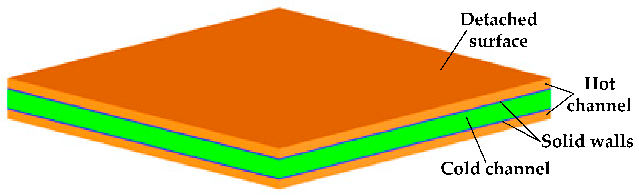
2. Physical and Numerical Model

The physical model of this numerical study is a gas-to-gas plate heat exchanger, which is used in a cabinet cooling system. The computational domain includes one hot channel and one cold channel. The channels are separated by two solid plates, as shown in Figure 1. The hot channel is detached from the center and a periodic boundary is used between the detached surfaces. The size of plate is 50 mm × 50 mm with a thickness of 0.2 mm and the distance between plates is 2.5 mm. The computational models are established for cross-flow, counter-flow and parallel-flow plate heat exchangers.
Both hot fluid and cold fluid are considered as incompressible, turbulent and steady. In the Cartesian tensor system, the continuity, momentum and energy equations are described as follow [26,28]:
x i ( ρ u i ) = 0 ,
x j ( ρ u i u j ) = p x i + x j [ μ ( u i x j + u j x i 2 3 δ ij u k x k ) ] + x j ( ρ u i u j ¯ ) ,
x i [ u i ( ρ E + p ) ] = x j [ ( λ + c p μ t P r t ) T x j ] ,
where E is the total enthalpy, μ t is the turbulent viscosity, Prt is the turbulent Prandtl number, ρ u i u j ¯ is defined as:
ρ u i u j ¯ = μ t ( u i x j + u j x i ) 2 3 ( ρ k + μ t u k x k ) δ ij ,
Plate heat exchangers are always studied by CFD simulations and a good agreement with experimental results were obtained by using low Reynolds number k-ε model (LRKE) for both liquid [21] and gas [29]. LRKE is used in this study. In LRKE the turbulence kinetic energy k and turbulence dissipation rate ε are solved using following equations [26]:
t ( ρ k ) + x j [ ρ u j k ( μ + μ t σ k ) k x j ] = μ t ( P + P B ) ρ ε 2 3 ( μ t u i x j + ρ k ) u i x j + μ t P NL ,
t ( ρ ε ) + x j [ ρ u j ε ( μ + μ t σ ε ) ε x j ] = C ε 1 ε k { μ t ( P + P NL + P ) 2 3 ( μ t u i x i + ρ k ) u i x i } + C ε 3 ε k μ t P B C ε 2 ( 1 0.3 e R t 2 ) ρ ε 2 k + C ε 4 ρ ε u i x i ,
The governing equations are solved by using the finite volume method. The second upwind differential scheme and SIMPLE algorithm are applied.
The Reynolds number ReH based on channel height, i.e., distance between the plates, is always applied for dimpled plate channel and baseline flat plate channel in both numerical [30,31] and experimental studies [32]. The Reynolds number ReH used in this study is given as:
R e H = ρ U H μ ,
where U is the area-averaged velocity in the channel.
The Nusselt number Nu is defined as:
N u = q ¯ H λ ( T w T f ) ,
where q ¯ is the average heat flux through the solid plate and the flow average temperature Tf is:
T f = T in + T out 2 ,
The Fanning friction factor f is defined as:
f = Δ p H 2 ρ U 2 L
where Δ p is the pressure loss in the channel and L is the channel length in flow direction.

3. Heat Transfer Models with and without Longitudinal Heat Conduction

Actual heat transfer process in a plate heat exchanger includes transverse heat conduction (THC) and longitudinal heat conduction (LHC), as shown in Figure 2. The plate absorbs the heat from the hot fluid and releases it to the cold fluid by THC. The heat transfer model with LHC as general heat transfer model includes both THC and LHC. The heat flux between fluids is mainly transferred by the THC, whereas in plate the heat flux is transferred by LHC, the LHC heat flux q LHC for every infinitesimal element can be defined as:
q LHC = q c q h ,
where q c and q h are cold side heat flux and hot side heat flux, respectively.
The heat transfer model without LHC prevents small-scale LHC in the plate. The side surfaces of every infinitesimal element in the plate perpendicular to longitudinal directions are imposed adiabatic boundaries [26,27]. There is no LHC between infinitesimal elements, as shown in Figure 3.
The heat transfer model without LHC is established to study the effect of small-scale LHC. The effect of small-scale LHC is clearly illustrated by temperature and heat flux contours of the heat transfer models.
In the present study, the contribution of longitudinal heat conduction η, which is obtained from the difference of average heat flux of the heat transfer models with LHC q ¯ wi and without LHC q ¯ wo , is defined as:
η = q ¯ wi q ¯ wo q ¯ wi ,
The contribution of longitudinal heat conduction η can be used to describe the effect of small-scale LHC. If the value is above zero, the effect of small-scale LHC enhances the thermal performance of the heat exchanger. Else, the effect of small-scale LHC reduces the thermal performance of the heat exchanger.

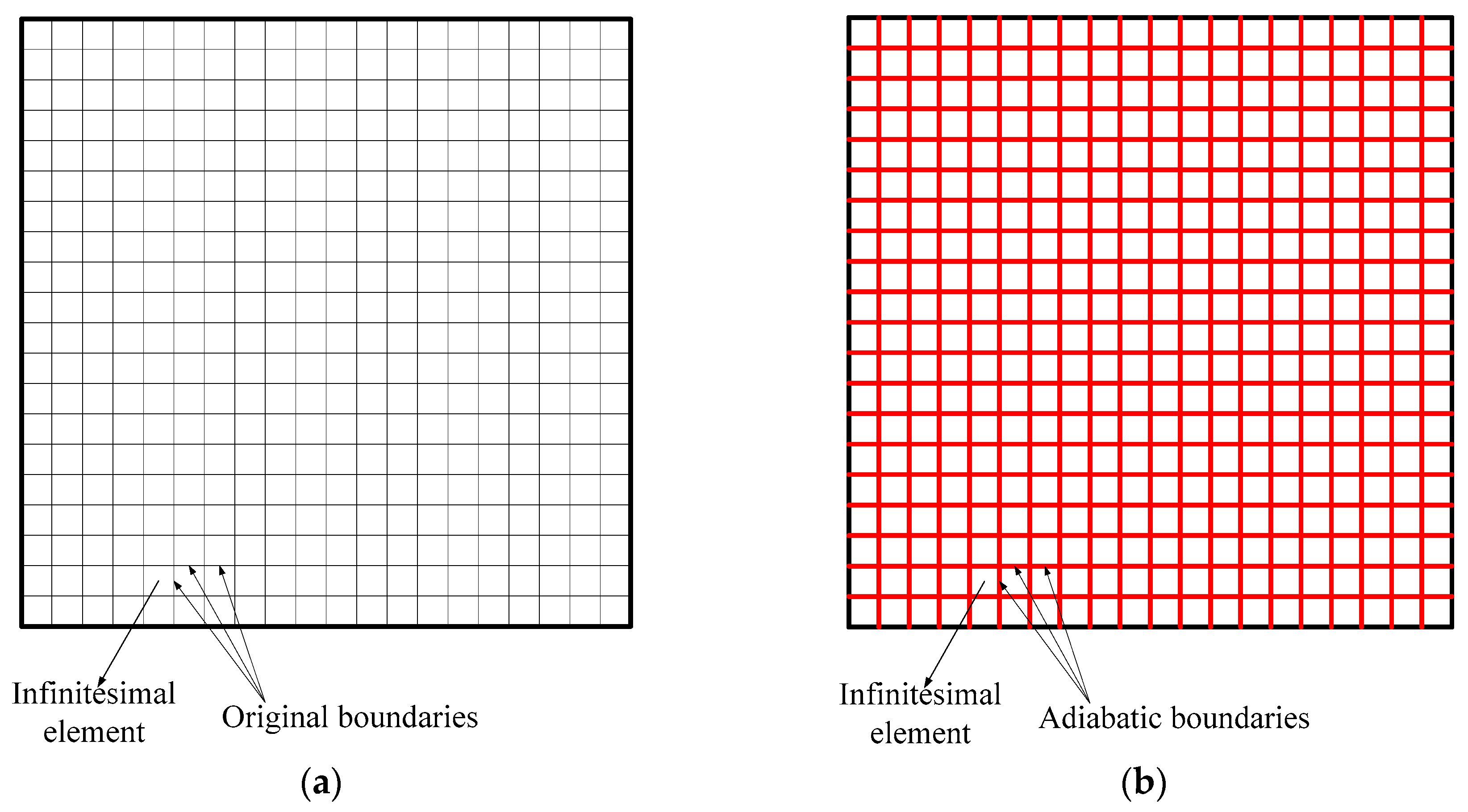
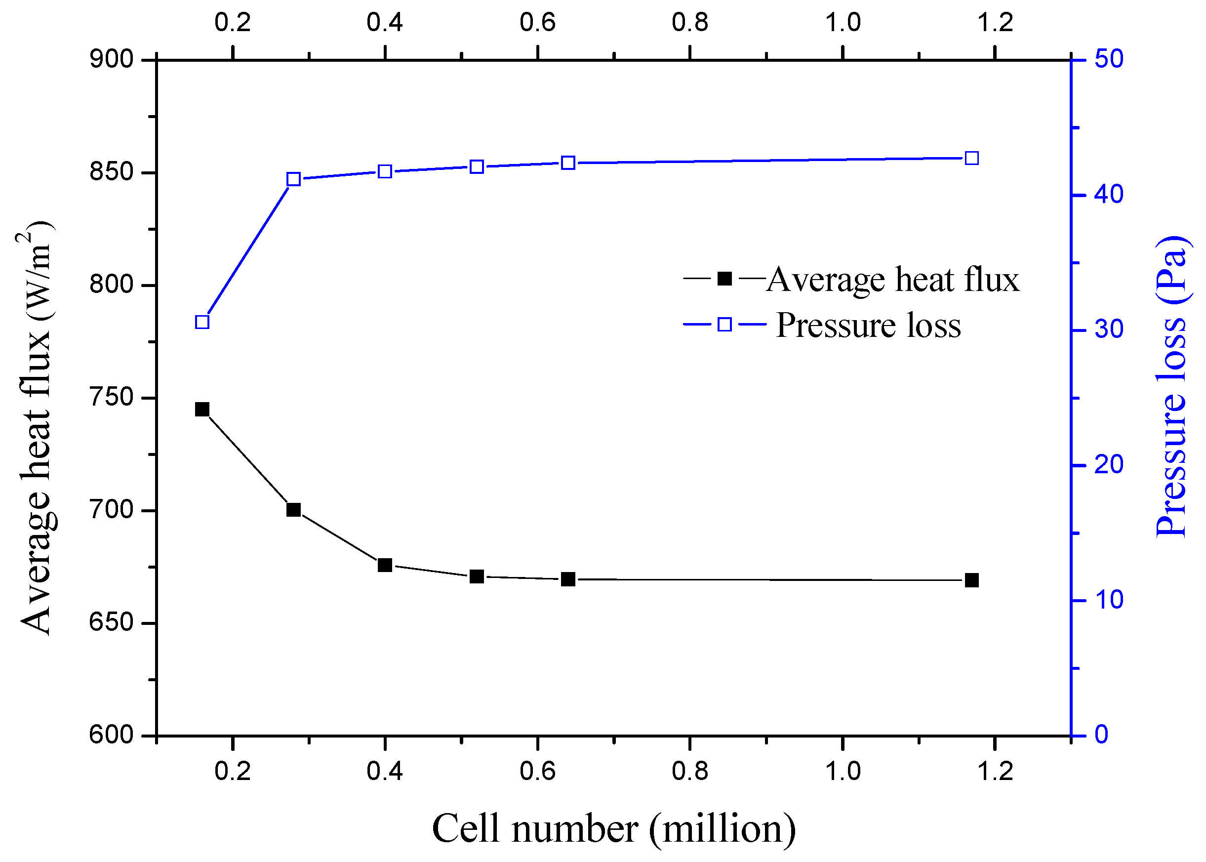
4. Grid Independence and Code Validation

In this paper, the parameters in the heat transfer models with and without LHC for cross-flow, counter-flow and parallel-flow plate heat exchangers are the same. The heat transfer model with LHC of the cross-flow plate heat exchanger is used to test the grid independence. The average heat flux and the pressure loss of hot flow along with the cell number of the model are shown in Figure 4. The average heat flux and the pressure loss are stable when the cell number is greater than 0.4 million. Models with 0.52 million cells are chosen to get the stable results and save the computational time.
The baseline Nusselt number Nu0 and the Fanning friction factor f0 in flat plate channel for transitional conditions are summarized by Zhang and Che [33], as follows:
{ N u 0 = 0.3726 ( R e H 0.8 57.4 ) P r 0.4 ( T f T w ) 0.45 f 0 = 0.06651 R e H 0.25 , 1150 R e H 2500 ,
They are used to validate the numerical code. The simulation results of this study for Reynolds number ReH from 1250 to 2430 show good agreements with both the baseline Nusselt number Nu0 and the Fanning friction factor f0. The maximum deviations of the Nusselt number and the Fanning friction factor are 4.9% and 9.7%, respectively. It validated that the present numerical method is reliable.
The distributions of heat flux on the plate surface of cross-flow plate heat exchanger are shown in Figure 5, Figure 6 and Figure 7. It is shown that the absolute values of hot side heat flux q h distribution and cold side heat flux q c distribution of the heat transfer model with LHC are nearly symmetrical along the diagonal of the plate. The absolute values of hot side heat flux q h distribution and cold side heat flux q c distribution of the plate of the heat transfer model without LHC are the same, which means that only THC occurs in the plate. It is proved by LHC heat flux q LHC distribution in the plate of cross-flow plate heat exchanger of the heat transfer model without LHC as shown in Figure 7b. Compared with real LHC heat flux q LHC distribution of the heat transfer model with LHC, as shown in Figure 7a, the LHC heat flux q LHC in the heat transfer model without LHC is negligible. For counter-flow and parallel-flow plate heat exchangers, the heat transfer model without LHC acts the same. It is indicated that small-scale LHC is prevented in heat transfer model without LHC. So the effect of small-scale LHC is analyzed well by the heat transfer models with and without LHC.

5. Results and Discussion

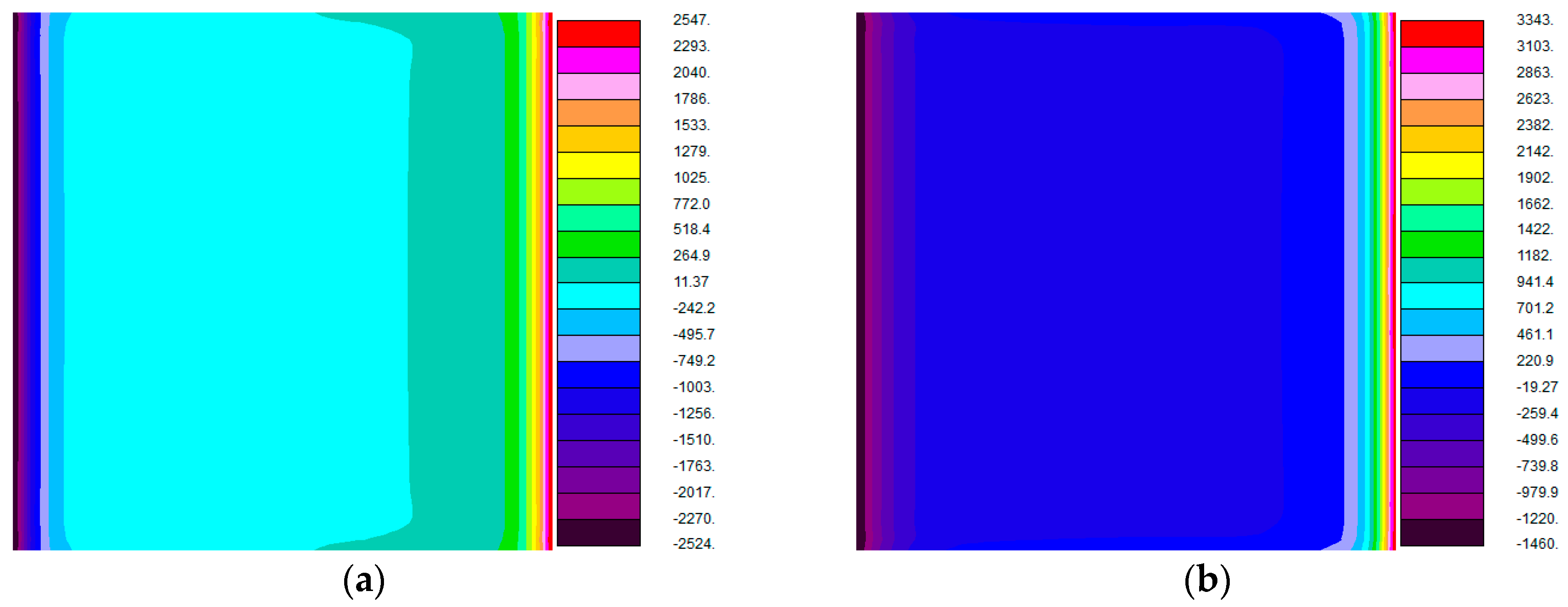
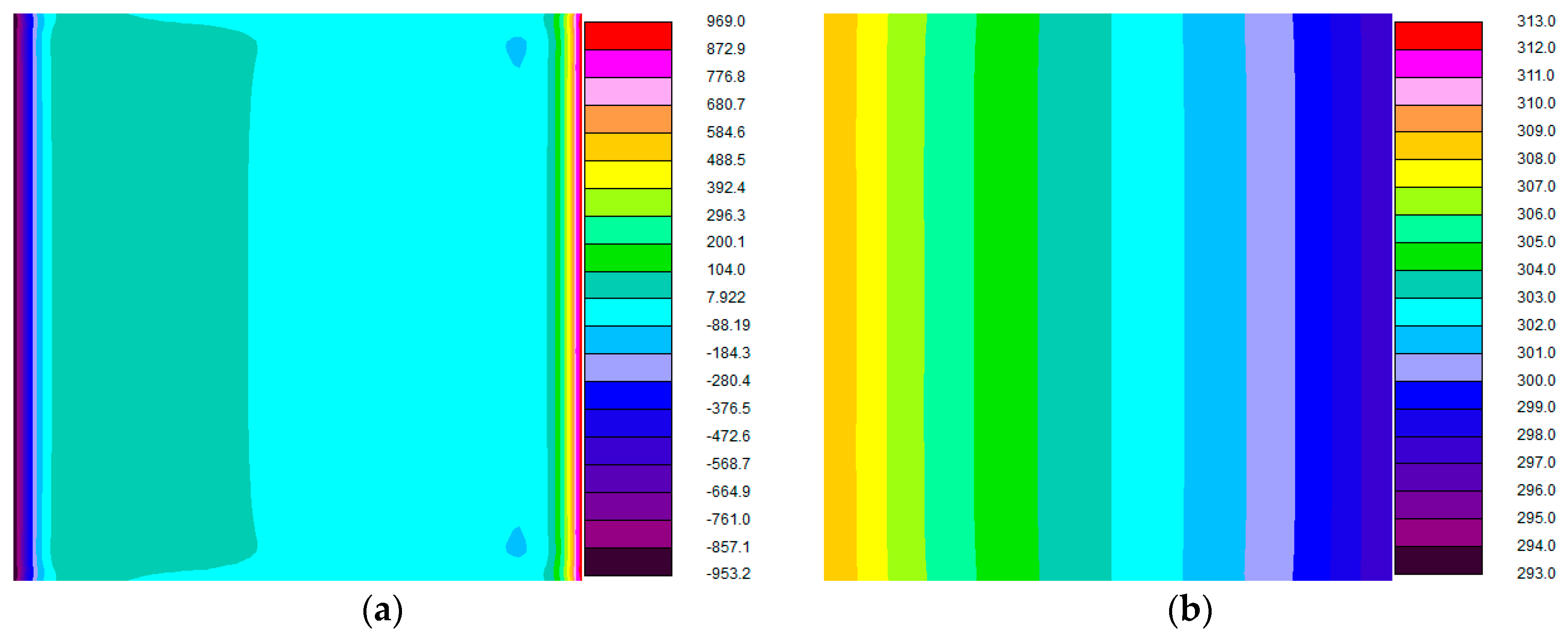
5.1. Effect of Small-Scale Longitudinal Heat Conduction on Balanced Flow

Balanced flow and unbalanced flow are always considered in the number of heat transfer unit (NTU) method for heat exchanger design [11]. Balanced flow means heat capacity rates of cold flow and hot flow are the same i.e., Cc/Ch = 1.
The small-scale LHC in the plate can be studied by the heat transfer models with and without LHC. The effect of LHC is clearly illustrated by the distributions of temperature and LHC heat flux. The temperature distributions of the plate in balanced flow for cross-flow and counter-flow plate heat exchangers are shown as Figure 8 and Figure 9, respectively.
For balanced flow, the average heat flux, contribution of longitudinal heat conduction, and plate temperature difference of different type of plate heat exchangers are summarized in Table 1. It is clear that a more uniform temperature profile of the plate is obtained due to small-scale LHC. The plate temperature differences in the cross-flow plate heat exchanger heat transfer models with and without LHC are 5.84 K and 16.44 K, respectively, and for counter-flow they are 5.37 K and 14.95 K. It means that in cross-flow and counter-flow plate heat exchangers non-negligible small-scale LHC occurs in the plate.
Actually, for balanced flow, small-scale LHC is very strong in both cross-flow and counter-flow plate heat exchangers. It is clearly shown from LHC heat flux distributions of the counter-flow and cross-flow plate heat exchangers heat transfer model with LHC, as indicated in Figure 10a and Figure 11a, respectively. The contributions of longitudinal heat conduction η of cross-flow and counter-flow plate heat exchangers are −0.09% and −3.15%, respectively. This means that, for balanced flow, the effect of small-scale LHC reduces the heat transfer performance of counter-flow plate heat exchanger. However, the small-scale LHC has little effect on the heat transfer performance of cross-flow plate heat exchanger in balanced flow.
The plate temperature differences in parallel-flow plate heat exchanger heat transfer model with and without LHC are 0.01 K and 0.04 K, respectively. For balanced flow, LHC heat flux distribution of parallel-flow plate heat exchanger using heat transfer model with LHC is shown in Figure 12a. It observed that a very weak small-scale LHC occurs in the plate and small-scale LHC has no effect on the heat transfer performance of parallel-flow plate heat exchanger in balanced flow. Actually, the contribution of longitudinal heat conduction η is zero in this condition.

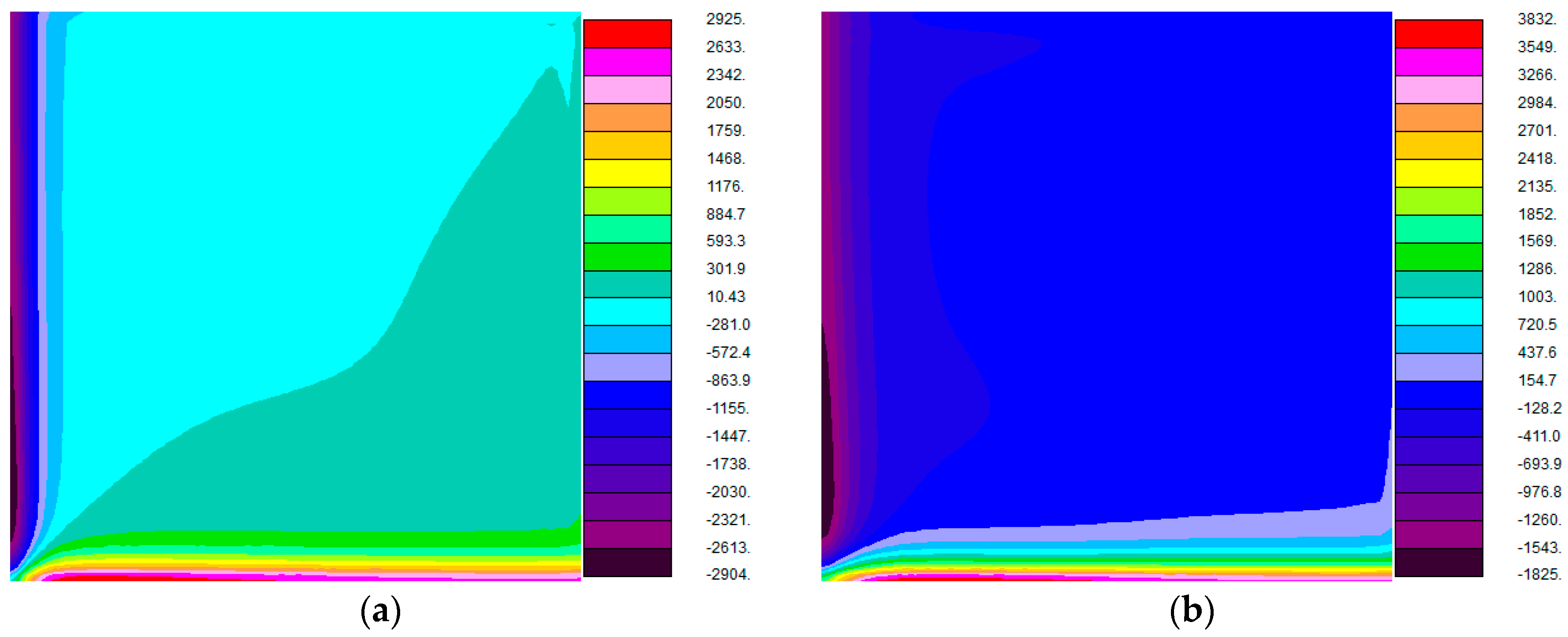
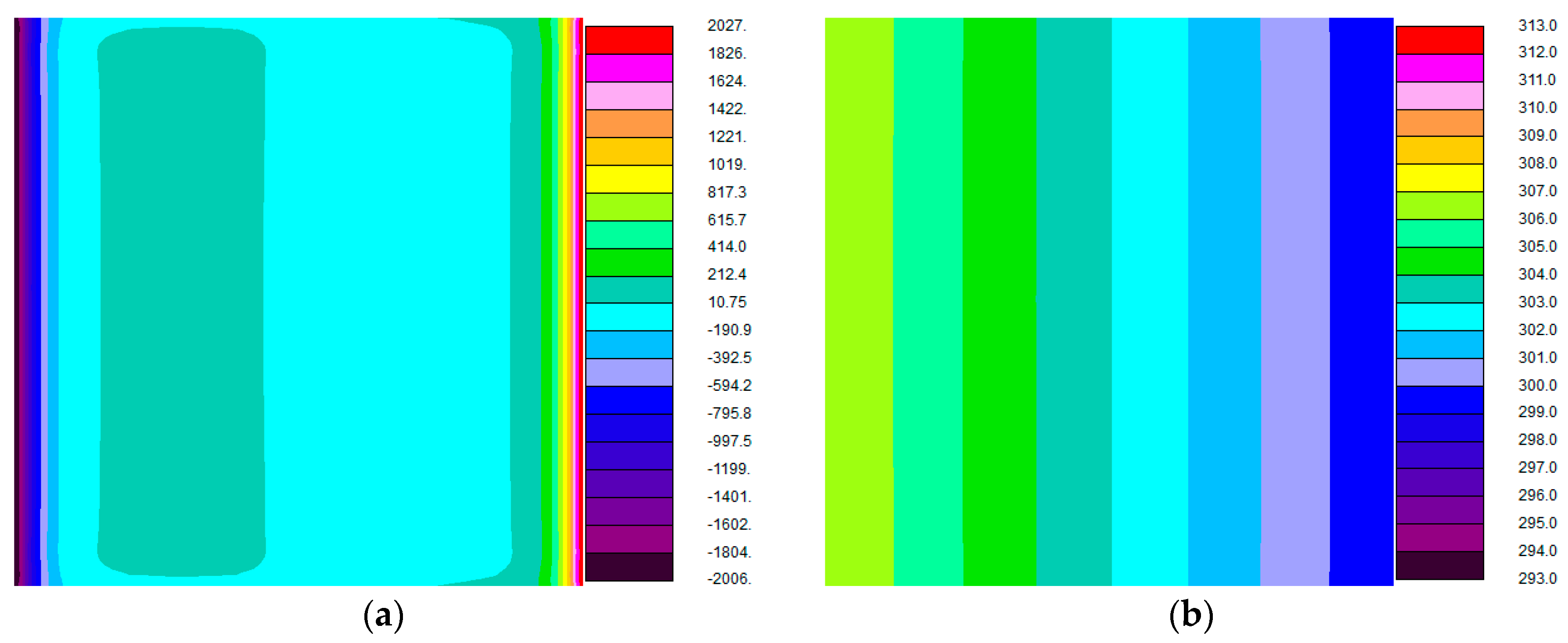
5.2. Effect of Small-Scale Longitudinal Heat Conduction on Unbalanced Flow

In this section, two kinds of unbalanced flow are considered first. Their ratios of heat capacity rates are Cc/Ch = 1.8 and Ch/Cc = 1.8, respectively. It is found that small-scale LHC has similar effects in both conditions for counter-flow, cross-flow and parallel-flow plate heat exchangers, so, only one of them is considered in this study, for which the ratio of heat capacity rates is Ch/Cc = 1.8.
For unbalanced flow, the plate temperature difference in counter-flow plate heat exchanger heat transfer models with and without LHC is 5.53 K and 13.85 K, respectively. The former one is bigger than that in balanced flow and the latter one is smaller. It is indicated that small-scale LHC is weaker in unbalanced flow than that in balanced flow. It is clearly illustrated by the plate LHC heat flux distributions of counter-flow plate heat exchanger in Figure 10. For unbalanced flow, average heat flux; contribution of longitudinal heat conduction; plate temperature difference of different type of plate heat exchangers are summarized in Table 2. In this condition, the average heat flux of the plate for unbalanced flow and balanced flow are 869.495 W/m2 and 680.67 W/m2, respectively. Moreover, the variation of LHC heat flux for unbalanced flow and balanced flow are 4803 W/m2 and 5071 W/m2, respectively.
Similarly, for a cross-flow plate heat exchanger, the small-scale LHC is weaker in unbalanced flow than that in balanced flow. The plate LHC heat flux distributions are shown in Figure 11. And, plate temperature difference in cross-flow plate heat exchanger heat transfer models with and without LHC are 6 K and 15.52 K, respectively.
Many researchers have pointed out that LHC degraded the heat transfer performance [6,9]. It is easily found that the heat transfer performance is greatly reduced by a strong LHC effect. In this study, a similar situation is obtained by using heat transfer model with LHC. It is indicated the weaker small-scale LHC achieves higher heat transfer performance, so less reduction of the heat transfer performance occurs for a counter-flow plate heat exchanger in the unbalanced flow as compared with the balanced flow. The contribution of longitudinal heat conduction η for counter-flow heat exchanger in unbalanced flow and balanced flow are −1.73% and −3.15%, respectively. For a cross-flow plate heat exchanger they are 0.53% and −0.09%, respectively. For unbalanced flow, the heat transfer performance of cross-flow plate heat exchanger is enhanced slightly. For unbalanced flow, the LHC heat flux distribution of parallel-flow plate heat exchanger of heat transfer model with LHC is shown in Figure 12b. Small-scale LHC is very strong in this condition. However, the effect of small-scale LHC on the heat transfer performance is still very small. The contribution of longitudinal heat conduction η is 0.05%.

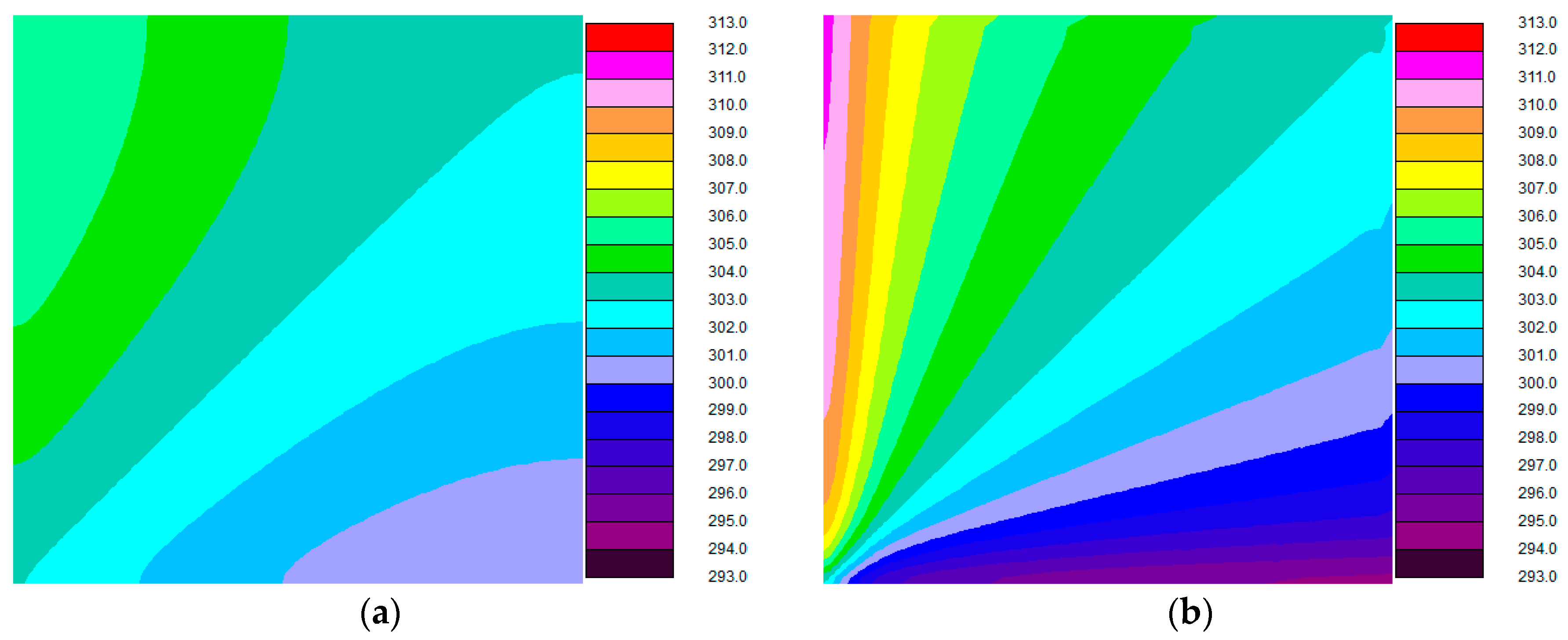
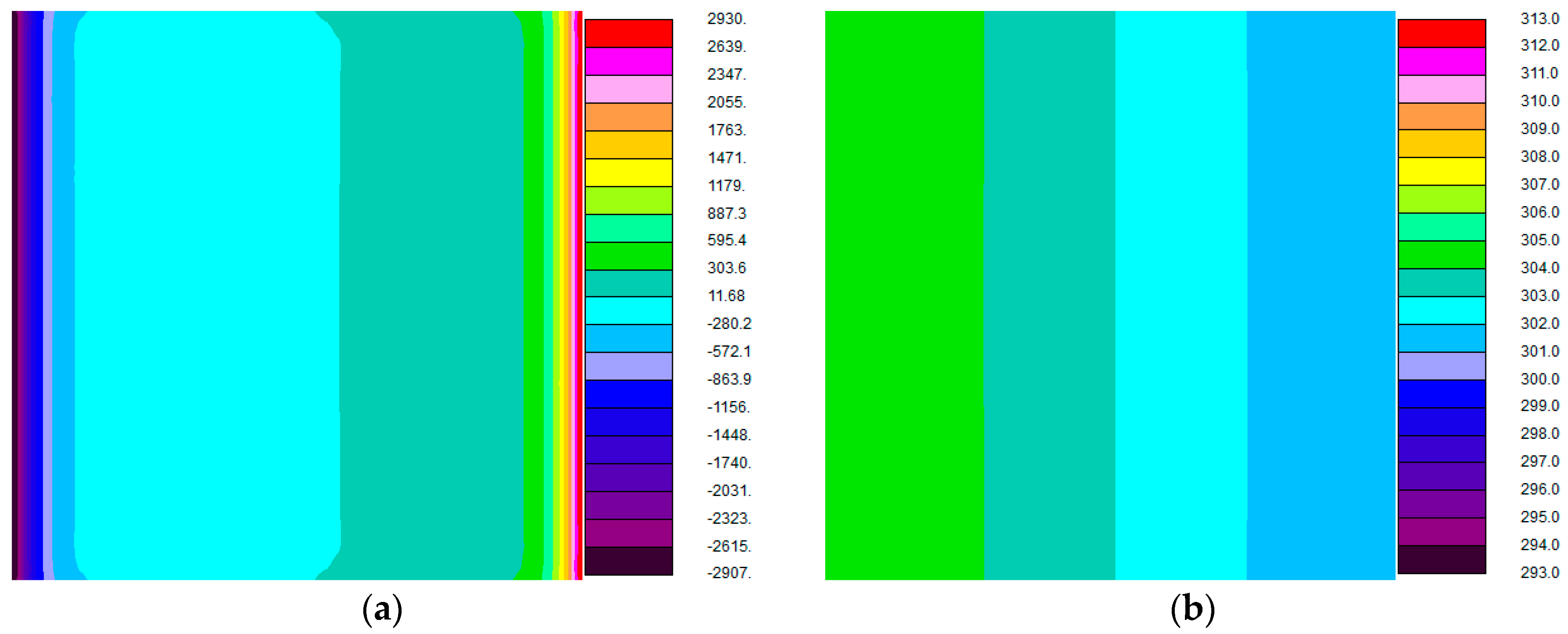
5.3. Effect of Plate Thermal Conductivity on Small-Scale Longitudinal Heat Conduction

Both THC and LHC are strongly influenced by the thermal conductivity λm of the plate material. Three different materials have been studied i.e., stainless-steel (λm = 15.1 W/(m·K)), brass (λm = 109 W/(m·K)) and silver (λm = 427 W/(m·K)). A counter-flow plate heat exchanger in balanced flow is used to study the effect of different materials.
For all the materials, the numerical results of the heat transfer model without LHC are the same. It is thus indicated that the thermal resistance in the transverse direction is negligible, even for stainless-steel due to the much lesser thickness of the plate, so the different materials have the same effect on the plate THC.
The silver plate heat exchanger achieves the strongest small-scale LHC due to its highest thermal conductivity λm. This is clearly shown in Figure 13a, Figure 14a and Figure 15a. The higher the thermal conductivity λm, the bigger is the plate LHC heat flux. As shown in Figure 13b, Figure 14b and Figure 15b, the stronger the small-scale LHC the more uniform a temperature profile of the plate is obtained. For different plate materials, the average heat flux, contribution of longitudinal heat conduction, and plate temperature difference of a counter-flow plate heat exchanger are summarized in Table 3.
The contributions of longitudinal heat conduction η for stainless-steel, brass and silver under the same conditions are −0.54%, −2.07% and −4.01%, respectively. It is indicated that a plate with high thermal conductivity λm, such as silver plate, has a strong influence on LHC and reduces the thermal performance significantly.

6. Conclusions

The longitudinal heat conduction in plate heat exchangers is investigated in this paper. Heat transfer models with and without longitudinal heat conduction are established to study the small-scale longitudinal heat conduction. The performance of small-scale longitudinal heat conduction is illustrated by temperature and heat flux contours in the heat transfer models with and without longitudinal heat conduction. The conclusions could be summarized as follows:
(1)
Small-scale longitudinal heat conduction occurs in the plate and a more uniform temperature profile of the plate can be obtained due to small scale longitudinal heat conduction. In balanced flow, the contributions of longitudinal heat conduction of counter-flow and cross-flow plate heat exchangers are −3.15% and −0.09%, respectively. The effect of small-scale longitudinal heat conduction reduces the heat transfer performance significantly for counter-flow plate heat exchanger, whereas for cross-flow plate heat exchanger the heat transfer performance is reduced slightly. For the parallel-flow plate heat exchanger small-scale longitudinal heat conduction is very weak and the contribution of longitudinal heat conduction is zero. The small-scale longitudinal heat conduction has no effect on parallel-flow plate heat exchanger in balanced flow.
(2)
In unbalanced flow, the small-scale longitudinal heat conduction is weakened for both counter-flow and cross-flow plate heat exchangers. The contributions of longitudinal heat conduction of these two heat exchangers are −1.73% and 0.53%, respectively. For counter-flow plate heat exchanger, the effect of small-scale longitudinal heat conduction reduces the heat transfer performance lesser than that in balanced flow, whereas the effect of small-scale longitudinal heat conduction enhance the heat transfer performance of cross-flow plate heat exchangers. For parallel-flow plate heat exchanger, the small-scale longitudinal heat conduction is strengthened significantly in unbalanced flow. However, the contribution of longitudinal heat conduction is only 0.05%.
(3)
The small-scale longitudinal heat conduction is influenced by thermal conductivity of the plate. The contributions of longitudinal heat conduction for counter-flow stainless-steel, brass and silver plate heat exchangers in balanced flow are −0.54%, −2.07% and −4.01%, respectively. The higher the thermal conductivity of the plate, the stronger the small-scale longitudinal heat conduction and the larger the thermal performance reduction.

Author Contributions

S.B. proposed the model, performed simulation and wrote the paper; T.M. participated in analysis and revised the paper; M.Z. contributed to writing and revising the paper; Q.W. supervised the work and revised the paper. All authors contributed to this work.

Funding

This research was funded by State Key Program of National Natural Science of China (Grant No. 51536007) and the Foundation for Innovative Research Groups of the National Natural Science Foundation of China (Grant No. 51721004).

Conflicts of Interest

The authors declare no conflict of interest.

Nomenclature

Cheat capacity rate, W/K
cpspecific heat, J/(kg·K)
fFanning friction factor
f0baseline Fanning friction factor
Hchannel height
kturbulence kinetic energy
Lplate length, m2/s2
NuNusselt number
Nu0baseline Nusselt number
pstatic pressure
PrPrandtl number
Prtturbulent Prandtl number
q heat flux, W/m2
q LHC longitudinal heat conduction heat flux, W/m2
q ¯ average heat flux, W/m2
ReHReynolds number based on channel height
Ttemperature, K
Uarea-averaged velocity in inlet section, m/s
uvelocity, m/s
Greek
ηcontribution of longitudinal heat conduction, %
λfluid thermal conductivity, W/(m·K)
λmsolid thermal conductivity, W/(m·K)
μ dynamic viscosity, Pa·s
μ t turbulent viscosity
ρdensity, kg/m3
Subscripts
i, j1, 2, 3
ccold side
hhot side
fflow
wsolid wall
ininlet
outoutlet
wiheat transfer model with longitudinal heat conduction
woheat transfer model without longitudinal heat conduction

References

  1. Wang, Q.W.; Zeng, M.; Ma, T.; Du, X.P.; Yang, J.F. Recent development and application of several high-efficiency surface heat exchangers for energy conversion and utilization. Appl. Energy 2014, 135, 748–777. [Google Scholar] [CrossRef]
  2. Bhutta, M.M.A.; Hayat, N.; Bashir, M.H.; Khan, A.R.; Ahmad, K.N.; Khan, S. CFD applications in various heat exchangers design: A review. Appl. Therm. Eng. 2012, 32, 1–12. [Google Scholar] [CrossRef]
  3. Ranganayakulu, C.; Luo, X.; Kabelac, S. The single-blow transient testing technique for offset and wavy fins of compact plate-fin heat exchangers. Appl. Therm. Eng. 2017, 111, 1588–1595. [Google Scholar] [CrossRef]
  4. Ranganayakulu, C.; Pallavi, P. Development of heat transfer coefficient and friction factor correlations for offset fins using CFD. Int. J. Numer. Methods Heat Fluid Flow 2011, 21, 935–951. [Google Scholar]
  5. Ranganayakulu, C.; Seetharamu, K.N.; Sreevatsan, K.V. The effects of longitudinal heat conduction in compact plate-fin and tube-fin heat exchangers using a finite element model. Int. J. Heat Mass Transf. 1997, 40, 1261–1277. [Google Scholar] [CrossRef]
  6. Ranganayakulu, C.; Seetharamu, K.N. The combined effects of longitudinal heat conduction, flow nonuniformity and temperature nonuniformity in crossflow plate-fin heat exchangers. Int. Commun. Heat Mass Transf. 1999, 26, 669–678. [Google Scholar] [CrossRef]
  7. Ranganayakulu, C.; Seetharamu, K.N. The combined effects of wall longitudinal heat conduction and inlet fluid flow maldistribution in crossflow plate-fin heat exchangers. Heat Mass Transf. 2000, 36, 247–256. [Google Scholar] [CrossRef]
  8. Venkatarathnam, G.; Narayanan, S.P. Performance of a counter flow heat exchanger with longitudinal heat conduction through the wall separating the fluid streams from the environment. Cryogenics 1999, 39, 811–819. [Google Scholar] [CrossRef]
  9. Narayanan, S.P.; Venkatarathnam, G. Performance degradation due to longitudinal heat conduction in very high NTU counterflow heat exchangers. Cryogenics 1998, 38, 927–930. [Google Scholar] [CrossRef]
  10. Kumar, S.S.; Raju, L.R.; Nandi, T.K. Thermal performance of perforated plate matrix heat exchangers with effects from outer wall and flow channel geometry. Cryogenics 2015, 72, 153–160. [Google Scholar] [CrossRef]
  11. Raju, L.R.; Nandi, T.K. Effective NTU of a counterflow heat exchanger with unbalanced flow and longitudinal heat conduction through fluid separating and outer walls. Appl. Therm. Eng. 2017, 112, 1172–1177. [Google Scholar] [CrossRef]
  12. Arici, M.E. Heat transfer analysis for a concentric tube heat exchanger including the wall axial conduction. Heat Transf. Eng. 2010, 31, 1034–1041. [Google Scholar] [CrossRef]
  13. Heidarinejad, G.; Moshari, S. Novel modeling of an indirect evaporative cooling system with cross-flow configuration. Energy Build. 2015, 92, 351–362. [Google Scholar] [CrossRef]
  14. Hettiarachchi, H.D.M.; Golubovic, M.; Worek, W.M. The effect of longitudinal heat conduction in cross flow indirect evaporative air coolers. Appl. Therm. Eng. 2007, 27, 1841–1848. [Google Scholar] [CrossRef]
  15. Lin, T.Y.; Kandlikar, S.G. A theoretical model for axial heat conduction effects during single-phase flow in microchannels. J. Heat Transf. 2012, 134, 020902. [Google Scholar] [CrossRef]
  16. Rahimi, M.; Mehryar, R. Numerical study of axial heat conduction effects on the local Nusselt number at the entrance and ending regions of a circular microchannel. Int. J. Therm. Sci. 2012, 59, 87–94. [Google Scholar] [CrossRef]
  17. Maranzana, G.; Perry, I.; Maillet, D. Mini- and micro-channels: Influence of axial conduction in the walls. Int. J. Heat Mass Transf. 2004, 47, 3993–4004. [Google Scholar] [CrossRef]
  18. Lin, M.; Wang, Q.W.; Guo, Z.X. Investigation on evaluation criteria of axial wall heat conduction under two classical thermal boundary conditions. Appl. Energy 2016, 162, 1662–1669. [Google Scholar] [CrossRef]
  19. Abu-Khader, M.M. Plate heat exchangers: Recent advances. Renew. Sustain. Energy Rev. 2012, 16, 1883–1891. [Google Scholar] [CrossRef]
  20. Miao, Q.W.; You, S.J.; Zheng, W.D.; Zheng, X.J.; Zhang, H.; Wang, Y.R. A grey-box dynamic model of plate heat exchangers used in an urban heating system. Energies 2017, 10, 1398. [Google Scholar] [CrossRef]
  21. Ciofalo, M.; Stasiek, J.; Collins, M.W. Investigation of flow and heat transfer in corrugated passages—II. Numerical simulations. Int. J. Heat Mass Transf. 1996, 39, 165–192. [Google Scholar] [CrossRef]
  22. Rogiers, F.; Baelmans, M. Towards maximal heat transfer rate densities for small-scale high effectiveness parallel-plate heat exchangers. Int. J. Heat Mass Transf. 2010, 53, 605–614. [Google Scholar] [CrossRef]
  23. Buckinx, G.; Rogiers, F.; Baelmans, M. Thermal design and optimization of small-scale high effectiveness cross-flow heat exchangers. Int. J. Heat Mass Transf. 2013, 60, 210–220. [Google Scholar] [CrossRef]
  24. Ciofalo, M. Local effects of longitudinal heat conduction in plate heat exchangers. Int. J. Heat Mass Transf. 2007, 50, 3019–3025. [Google Scholar] [CrossRef]
  25. Doo, J.H.; Ha, M.Y.; Min, J.K.; Stieger, R.; Rolt, A.; Son, C. Theoretical prediction of longitudinal heat conduction effect in cross-corrugated heat exchanger. Int. J. Heat Mass Transf. 2012, 55, 4129–4138. [Google Scholar] [CrossRef]
  26. Ma, T.; Zhang, J.; Borjigin, S.; Chen, Y.T.; Wang, Q.W.; Zeng, M. Numerical study on small-scale longitudinal heat conduction in cross-wavy primary surface heat exchanger. Appl. Therm. Eng. 2015, 76, 272–282. [Google Scholar] [CrossRef]
  27. Borjigin, S.; Peng, Y.Y.; Ma, T.; Chen, Y.T.; Zeng, M.; Wang, Q.W. Parameter study on longitudinal heat conduction in a cross-wavy primary surface heat exchanger. In Proceedings of the 1st Thermal and Fluid Engineering Summer Conference, New York, NY, USA, 9–12 August 2015. [Google Scholar]
  28. CD-adapco; Methodology, STAR-CD. Version 4.16 CD-adapco; CD-adapco: Melville, NY, USA, 2011. [Google Scholar]
  29. Zhang, L.; Che, D.F. Turbulence models for fluid flow and heat transfer between cross-corrugated plates. Numer. Heat Transf. A 2011, 60, 410–440. [Google Scholar] [CrossRef]
  30. Elyyan, M.A.; Rozati, A.; Tafti, D.K. Investigation of dimpled fins for heat transfer enhancement in compact heat exchangers. Int. J. Heat Mass Transf. 2008, 51, 2950–2966. [Google Scholar] [CrossRef]
  31. Won, S.Y.; Ligrani, P.M. Numerical predictions of flow structure and local Nusselt number ratios along and above dimpled surfaces with different dimple depths in a channel. Numer. Heat Transf. A 2004, 46, 549–570. [Google Scholar] [CrossRef]
  32. Ligrani, P.M.; Burgess, N.K.; Won, S.Y. Nusselt numbers and flow structure on and above a shallow dimpled surface within a channel including effects of inlet turbulence intensity level. J. Turbomach. 2005, 127, 321–330. [Google Scholar] [CrossRef]
  33. Zhang, L.; Che, D.F. Influence of corrugation profile on the thermalhydraulic performance of cross-corrugated plates. Numer. Heat Transf. A 2011, 59, 267–296. [Google Scholar] [CrossRef]
Figure 1. Computational domain of plate heat exchanger.
Energies 11 01727 g001
Figure 2. Actual heat transfer in plate.
Energies 11 01727 g002
Figure 3. Boundaries of the plate (a) Heat transfer model with Longitudinal heat conduction (LHC); (b) Heat transfer model without LHC.
Energies 11 01727 g003
Figure 4. Grid independence.
Energies 11 01727 g004
Figure 5. The plate hot side heat flux q h distributions of cross-flow plate heat exchanger (a) Heat transfer model with LHC; (b) Heat transfer model without LHC.
Energies 11 01727 g005
Figure 6. The plate cold side heat flux q c distributions of cross-flow plate heat exchanger (a) Heat transfer model with LHC; (b) Heat transfer model without LHC.
Energies 11 01727 g006
Figure 7. The plate LHC heat flux q LHC distributions of cross-flow plate heat exchanger (a) Heat transfer model with LHC; (b) Heat transfer model without LHC.
Energies 11 01727 g007
Figure 8. The plate temperature distributions of cross-flow plate heat exchanger (a) Heat transfer model with LHC; (b) Heat transfer model without LHC.
Energies 11 01727 g008
Figure 9. The plate temperature distributions of counter-flow plate heat exchanger (a) Heat transfer model with LHC; (b) Heat transfer model without LHC.
Energies 11 01727 g009
Figure 10. The plate LHC heat flux distributions of counter-flow plate heat exchanger heat transfer model with LHC (a) Balanced flow; (b) Unbalanced flow.
Energies 11 01727 g010
Figure 11. The plate LHC heat flux distributions of cross-flow plate heat exchanger heat transfer model with LHC (a) Balanced flow; (b) Unbalanced flow.
Energies 11 01727 g011
Figure 12. The plate LHC heat flux distributions of parallel-flow plate heat exchanger heat transfer model with LHC (a) Balanced flow; (b) Unbalanced flow.
Energies 11 01727 g012
Figure 13. Counter-flow stainless-steel plate heat exchanger heat transfer model with LHC (a) The plate LHC heat flux distribution; (b) The plate temperature distribution.
Energies 11 01727 g013
Figure 14. Counter-flow brass plate heat exchanger heat transfer model with LHC (a) The plate LHC heat flux distribution; (b) The plate temperature distribution.
Energies 11 01727 g014
Figure 15. Counter-flow silver plate heat exchanger heat transfer model with LHC (a) The plate LHC heat flux distribution; (b) The plate temperature distribution.
Energies 11 01727 g015
Table 1. Results of calculation for different heat exchangers in balanced flow: average heat flux q ¯ ; contribution of longitudinal heat conduction η; plate temperature difference.
Type of Heat Exchanger q ¯ , W/m2η, %Plate Temperature Difference, K
wiwowiwo
Counter-flow680.67702.13−3.155.3714.95
Cross-flow667.96668.57−0.095.8416.44
Parallel-flow660.52660.5200.010.04
Table 2. Results of calculation for different heat exchangers in unbalanced flow: average heat flux q ¯ ; contribution of longitudinal heat conduction η; plate temperature difference.
Type of Heat Exchanger q ¯ , W/m2η, %Plate Temperature Difference, K
wiwowiwo
Counter-flow869.495884.515−1.735.5313.85
Cross-flow858.225853.6850.53615.52
Parallel-flow853.53853.0850.050.642.99
Table 3. Results of calculation for different plate materials counter-flow plate heat exchanger in balanced flow: average heat flux q ¯ ; contribution of longitudinal heat conduction η; plate temperature difference.
Plate Material/Thermal Conductivity, W/(m·K) q ¯ , W/m2η, %Plate Temperature Difference, K
wiwowiwo
Stainless-steel/15.1698.04701.81−0.5411.5514.94
Brass/109687.84702.11−2.077.4614.95
Silver/427675.05702.145−4.013.8214.95

