Electrically Driven Supersonic Combustion

Department of Aerospace and Mechanical Engineering, University of Notre Dame, Notre Dame, IN 46556, USA
Energies 2018, 11(7), 1733; https://doi.org/10.3390/en11071733
Submission received: 16 May 2018
/
Revised: 18 June 2018
/
Accepted: 28 June 2018
/
Published: 2 July 2018
(This article belongs to the Special Issue Electric Fields in Energy & Process Engineering)
Abstract
:This manuscript reviews published works related to plasma assistance in supersonic combustion; focusing on mixing enhancement, ignition and flameholding. A special attention is paid for studies, which the author participated in person. The Introduction discusses general trends in plasma-assisted combustion and, specifically, work involving supersonic conditions. In Section 2, the emphasis is placed on different approaches to plasma application for fuel ignition and flame stabilization. Several schemes of plasma-based actuators for supersonic combustion have been tested for flameholding purposes at flow conditions where self-ignition of the fuel/air mixture is not realizable due to low air temperatures. Comparing schemes indicates an obvious benefit of plasma generation in-situ, in the mixing layer of air and fuel. In Section 3, the problem of mixing enhancement using a plasma-based technique is considered. The mechanisms of interaction are discussed from the viewpoint of triggering gasdynamic instabilities promoting the kinematic stretching of the fuel-air interface. Section 4 is related to the description of transitional processes and combustion instabilities observed in plasma-assisted high-speed combustion. The dynamics of ignition and flame extinction are explored. It is shown that the characteristic time for reignition can be as short as 10 ms. Two types of flame instability were described which are related to the evolution of a separation zone and thermoacoustic oscillations, with characteristic times 10 ms and 1 ms correspondingly.
1. Introduction
An increasing interest in Plasma-Assisted Combustion (PAC) is motivated by a necessity to promote chemical reactions at unfavorable conditions such as far-from-stoichiometric composition, poor mixing, low gas temperature, high flow velocity, etc. With few exclusions, scientific and engineering research regarding PAC is still in the fundamental phase in general, and in the data accumulation phase for the case of supersonic environments particularly. A major expectation on how plasma could be employed for improvement of supersonic combustion (realized in scramjet engine) is due to its ability to promote the fuel ignition and support chemical reactions at low gas temperature in a wide range of pressure and fuel concentrations [1]. In terms of engine performance, this means a stable operation in an extended range of flight conditions, as it is shown in Figure 1. This qualitative diagram indicates that plasma assistance might be especially useful for air-breathing propulsion at a high-altitude, high Mach number portion of vehicle trajectory.
Most studies related to PAC can be separated into two domains. The first, basic, approach explores non-equilibrium plasma-chemical kinetics showing the great advantage of plasma techniques in terms of ignition time. Several manuscripts were focused on this approach, including reviews [3,4,5,6,7]; papers on non-equilibrium mechanisms of the combustion enhancement [8,9,10,11,12,13]; modelling [14,15], and others. These manuscripts cover the subject comprehensively, unveiling the major result on many experimental and theoretical studies: the non-equilibrium plasma of electric discharges is many times more effective to ignite a combustible mixture than heating. The “effectiveness” here is considered in terms of ignition delay time realized with equal energy deposited for the ignition source. This statement, illustrated in Figure 2, is a fundamental reason for great interest and practical hopefulness of the combustion community in the PAC technique. Non-equilibrium power deposition into the gas leads to the creation of a high concentration of species possessing higher reactivity in comparison with those found at equilibrium conditions, such as O, H, OH*, CH*, vibrationally excited molecules, etc. Despite the promising capabilities of increasing the reactivity and reducing ignition delay, it is not practical to implement such an approach for realistic high-speed engines with direct fuel injection. In most conditions a main limiting factor is rather slow mixing, resulting in strong gradients of fuel/oxidizer ratio across a combustion chamber. This is why it is important that the plasma is generated in situ, supplying reactive species to the place of fuel–oxidizer interaction, to diminish the effect of fast relaxation.
The second, applied, approach is dealing with more practical schemes of combustion devices aiming towards reliable ignition, mixing intensification, flame stabilization, enhancement of combustion completeness, and pollution control. Referencing just a few, the papers [1,16,17,18,19,20] give an initial impression on the field of PAC applications. In recent years, a few schemes of plasma-based actuators for supersonic combustion have been tested for flameholding purposes at flow conditions where self-ignition of the fuel/air mixture is not realizable due to low air temperatures [1,21,22,23,24,25,26]. These works demonstrated the potential of plasma-based techniques to improve combustion stability under supersonic flow conditions. However, the dominant pathway affecting the combustion and flameholding in supersonic flow with plasma assistance was not identified due to the complexity and interdependence of physical processes involved such as gasdynamic, electrodynamic, and chemical/plasma kinetic ones. Each of these processes includes a number of individual phenomena characterized with a wide range of time and spatial scales.
In most previous experiments, a supersonic model combustion chamber was used which contained a back-facing rim or cavity with a plasma generator which was used as an igniter for a combustible mixture in a low velocity (separated) zone of the flowfield. However, some previous experiments, using an alternative configuration in which electrical discharge was maintained over a flat wall [16,27,28], demonstrated the practicability of plasma employment for an effective flame anchoring in a supersonic combustion chamber without reliance on any mechanical elements. This approach is given special consideration in this work.
One of the most critical issues with the application of electrical discharges for supersonic combustion assistance is power management. The management of the combustion process in entire flowfield under unfavorable conditions requires an additional energy deposition of a magnitude similar to the flow enthalpy which is not of practical interest. It may be possible to reduce the energy deposition required through active control of chemical reaction rates and/or active control of a manifold of local ignition centers to force combustion under off-design conditions. The power deposition can be varied in time such that it can be reduced when the combustion support is not vitally important. This reduces, in average, the amount of energy required for plasma-assisted ignition and combustion maintenance. Even in this case of active control, the electric power density cannot be too low or it will no longer be an effective control authority of the flow structure and chemical reactions. This problem is partially resolved due to the non-equilibrium, non-uniform, and transient nature of electrical discharges, which deliver a synergy with thermal effects (heating). Those properties may be of critical importance for enhancing air-fuel mixing in compressible flows under non-premixed flow conditions [24,29,30]. Plasma-based ignition is the main focus, but mixing enhancement by plasma is the second principal focus of this work.
Other awkward problems arise for scramjet operation in transitional modes: fast start-up/restart; ram-to-scram transition; flame-front blow-offs; combustion instabilities; etc. Two main aspects are critically important at such an operation: a compulsory flameholding and fast mitigation of aftereffects of off-design operation. Experimental data, obtained recently [2,21,23,28], demonstrates that the plasma-based control system is capable of significantly extending the flammability limits. The plasma can impact the flow essentially without inertial effects.
Summarizing above, three main ideas underlie the concept of PAC in supersonic flow with direct fuel injection: (1) control of flow structure in the vicinity of the reaction zone; (2) gas heating and non-equilibrium excitation of fuel and oxidizer by the discharge in a mixing layer; and (3) fuel-air mixing enhancement due to flow instability generation. For flow structure control, the references [31,32,33,34,35] and the bibliographies therewith present a more-or-less circumstantial view on the state-of–the-art. This manuscript is focused on experimental studies and organized as follows: Section 2 is related to the problem of plasma-assisted ignition and flameholding in supersonic airflow; Section 3 describes the approach to mixing intensification; Section 4 considers transitional processes and instabilities; a short discussion is combined with the conclusions.
2. Plasma-Assisted Ignition and Flameholding in Supersonic Airflow
2.1. Early Efforts
Several experimental studies have been performed to demonstrate the electrical discharge capability for fuel ignition under conditions typical for scramjet operation. Probably the first paper related to plasma-assistance for scramjet operation was published in 1981 by the group of Drs. Kimura, Masuya, et al. [36,37,38]. In this work, the authors employed a plasma generator with an arc discharge between electrodes placed inside of the small volume with a fuel or different gas flowing through the arc. This technique was called “plasma jet” that has basically similar design as the “plasma torch” used in subsequent studies. It was shown that the injection of the plasma jet is effective for flame stabilization and promotion of combustion, when the position of injection is adequate. For example, in the supersonic airflow of M = 2.1 with low static temperature T = 154 K, intensive combustion was observed with the aid of a hydrogen plasma jet operated by a 4.7 kW electrical power expenditure (~2% of the chemical energy throughput). It was demonstrated that the ignition temperature almost linearly decreases as the torch electric power increased. It was also shown that the effectiveness of a nitrogen plasma on the promotion of combustion is nearly equal to that of hydrogen plasma, although, in the valuation based on input electrical power the nitrogen plasma jet is superior to the hydrogen plasma jet.
Starting from 1984, the group from Virginia Tech, headed by Dr. W. O’Brien, published the results of their studies [39,40,41,42,43] related to the application of the “plasma torch” technique to model scramjet ignition. In general, the same technique was applied for supersonic ignition and flameholding by research groups from Tokai University [36], Tohoku University [44,45,46,47], Japan Aerospace Agency [48], AFRL [1,49,50], and some others [51]. Review of those publications can be found in [1]. During these efforts, many configurations, operation modes, and injected gases were tested. One of the typical images of the plasma torch interaction with a hydrogen jet injected upstream of the torch nozzle is shown in Figure 3 [46]. There the major role of the plasma power in the ignition pattern (ignition limit) was demonstrated. Figure 4a [48], shows the relationship between net input energy to the igniters and the total temperature of the airflow at the ignition limit for a bulk equivalence ratio of 0.4. Results of the plasma torch igniters (TI) with open symbols and those of the H2/O2 torch igniters for equivalence ratios φ(TI) = 1.0, 2.0, 3.0 with solid symbols are shown in Figure 4a. The combustion heat of the residual H2 of the fuel-rich H2/O2 torch igniter and that of H2 from the Ar + H2 plasma torch igniter were included in the total input energy. As shown, these works demonstrate a significant benefit of the plasma-based igniter compared to H2/O2 torch (pilot flame) in the reduction of the gas temperature threshold for ignition. The power budget of the plasma jet, about 5 kW, was significantly less than that for the thermal source, >30 kW. However, as it is shown in Figure 4b, the relative pressure increase at application of this technique was less than 0.1 independently on the working gas applied. If to define the efficiency η as the dimensionless pressure increase reduced to a relative plasma power , based on the published data it was less than 1. This may mean that, in this test, the combustion (chemical reactions) do not contribute significantly in the thermal balance of the flow.
In fact, the plasma torches produces a plume of hot gas, up to T = 5000 K, and some pool of radicals. In this configuration, the non-equilibrium plasma-chemical processes are significantly mitigated because the electric discharge is mostly located inside the torch ignitor. In [1], it was mentioned “As the constraints involved with the ignition process are further understood, this, in turn, will help evolve the design and use of the igniters and may also serve as a baseline against which to test new igniter concepts”. This prediction was further realized within new approaches. Nevertheless, plasma torches continue to be used for scramjet research due to their convenience and high reliability [23].
In the early 2000s, the number of publications on PAC grew significantly due to increased interest in employing the MHD technique and plasmas for flow control and combustion improvement in high-speed flow employing RF discharges [52,53,54,55], microwaves [56,57,58], direct current discharges [59,60], nanosecond discharges [14,61,62], and other types [63,64,65,66]. Since that time, the main expected benefit of using plasma was the highly non-equilibrium chemical kinetics [4,5], which in turn helps reduce the plasma power required for fuel-oxidizer mixture ignition. In these works, the tests were performed in geometric configurations which were not scramjet-like, though the motivation of this activity was mostly attributed to supersonic combustion improvement. A clear understanding of the non-equilibrium plasma benefits for accelerating fuel ignition motivates researchers for a type of plasma application where a high value of reduced electric field E/N is realized, such as a nanosecond pulse discharges, radio frequency, microwave plasmas, etc. Table 1, adapted from [67], shows results of a qualitative analysis of different types of electrical discharges from the viewpoint of combustion initiation. These data are not comprehensive: a large domain of non-self-sustained discharges and combinations of different types of electric discharges is not included. Most of those works demonstrate successful ignition; some efforts achieve close to a practical implementation [68] but not at supersonic conditions. Working perfectly in premixed, low-speed conditions, this technique reduced its capabilities at higher flow velocities, V > 100 m/s, an example is shown in Figure 5 [56].

The discharges listed in Table 1 possess significantly different characteristics such as power density, reduced electric field, time scale, morphology, etc. The nonequilibrium plasma is generated at high enough reduced electric field, E/N > 10−20 V·m2, which is typically realized in short-pulse or high-frequency discharges [4,7]. In the phase of the discharge propagation (ionization wave), it generates a pool of radicals and chemically active molecules [3,10] on a time scale comparable to the discharge propagation time, t = 10−9–10−6 s. This time is significantly shorter than a characteristic time of fuel ignition (induction time), t = 10−4–10−2 s being a strong function of the gas temperature, and a characteristic gasdynamic time, t = 10−4–10−3 s in a supersonic flow. However, at a later stage after electric breakdown and in the case of long-time discharges sustained with the flow, the reduced electric field significantly decreases which causes a modification in active species pool content [5,15,84]. In high-speed flows, the continuous discharges or zones of post-discharge relaxing plasma convect with the main flowfield because the drift velocity of ions is much lower than the flow speed, Vdi < 100 m/s [28,31,85]. The effect of a strong plasma-flow coupling is highly beneficial for fuel ignition due to a long time of plasma interaction with the same portion of air-fuel mixture, t ≥ 10−4 s.
The problem of supersonic flameholding appears to be even more challenging than the ignition: the ignition itself is important but may not be the most pressing issue to be resolved for successful operation of scramjet at variable conditions. The following factors are not less imperative: proper mixing, time of plasma-mixture interaction, plasma localization, and instabilities (plasma and combustion both). For a plasma treatment of the entire flowfield the power budget appears to still be extremely high, limiting the applications. A novel approach consisted of the employment of multi-point, repetitively pulsed plasma ignition schemes [86] and understanding that plasma has to be generated “in-situ” just in the location of fuel-oxidizer interaction and not inside of an external device [67].
2.2. Non-Equilibrium Ignition in Supersonic Airflow
This sub-section is focused on two greatly different tests employing non-equilibrium plasmas for non-premixed fuel ignition under conditions close to a scramjet configuration: (1) pulsed nanosecond discharge, by the Stanford University group headed by Profs. G. Mungal and M. Cappelli and (2) electron beam by the ITAM group headed by Dr. M. Goldfeld.
In the first test [87,88,89], a nanosecond pulsed plasma discharge located between two fuel jets was used to ignite and hold jet flames in supersonic crossflows, with a cavity or without the use of mechanical elements (cavity or wall step) for flame holding. In the configuration without the cavity, the fuel injection nozzles and discharge electrodes were mounted flush with the surface of the flat wall adjacent to the freestream flow. The non-equilibrium plasma was produced by repetitive pulses of 15 kV peak voltage, 10 ns pulse width, and 50 kHz repetition rate. Sonic or subsonic fuel jets (hydrogen and ethylene) were injected into an oxygen freestream of Mach numbers M = 1.7–2.4 and static temperature T0 = 900–1300 K, as it is shown in Figure 6a. Note, the plasma was generated “in-situ”; and the average plasma power was extremely low, down to Wpl = 10 W.
In this test, the flow/injection conditions were found for both H2 and C2H4 injection, when a stable ignition/combustion was realized with plasma on while it was not detected without plasma. This difference is well recognizable for hydrogen injection in Figure 6 via OH PLIF technique. Authors used an original schematic where the upstream fuel jet generated a subsonic zone with subsequent plasma-based ignition there. It was demonstrated that the plasma assisted pilot flame is capable of flameholding in the windward/leeward side of the main jet over a test time of approximately 300 µs, and appears to maintain combustion even during the time between discharge pulses (20 µs). Note, the conditions of this test are close to a self-ignition threshold that allows the use of a low plasma power. Use of a high-enthalpy pure oxygen flow made it even easier.
One more important conclusion, followed initially from another work of this group [13,76], was on the multistage mechanism of the plasma-assisted ignition. Authors mentioned [89] that “this plasma-enhanced supersonic combustion can be interpreted to occur in two stages. The first stage … seeds the hot boundary layer with fuel, and the partially mixed boundary layer is then subjected to a low power nanosecond pulsed plasma. Some plasma enhanced combustion of this stream takes place (as evidenced by OH PLIF). Radical production by this “pilot flame” (order of 10−2–10−3 in mole fraction at the … pilot flame region) … representing several orders of magnitude more than can be obtained by the discharge alone (order of 10−5), serves then, in the second stage, to ignite and sustain the combustion of the majority of the fuel, which is introduced downstream of the plasma”. Similar idea, based on tests with a Quasi-DC discharge, was announced in [90,91].
An idea to utilize an electron beam and combined E-beam plus optical, DC, or MW discharges for MHD flow control and scramjet combustion improvement was intensively discussed in mid 2000s [86,92,93,94]. Benefits were expected due to the lowest energetic cost of ionization by an E-beam and effective oxygen dissociation/radical’s elaboration in E-beam excited molecular plasma. Another advantage of the E-beam technique may be realized through an electrostatic repulsion of a binary mixture during liquid fuel atomization [86].
In [95], for ignition of non-premixed fuel in supersonic flow, a pulsed E-beam (duration several hundred microseconds, electron energy is about 10 kV) non-equilibrium plasma was applied. The main purposes of this study were to explore the feasibility of combustion control of hydrocarbon fuel by an electron beam. A scramjet model, equipped with a wall cavity, was tested at the following conditions at the combustor entrance: Mach number M = 3–5, total temperature T0 = 1500–2500 K, total pressure P0 = 0.8–4 bar, fuel-air equivalence ratio varied from 0.2 to 1.4. The electron beam had an angular aperture 180° and allows providing the beam diameter in combustor bigger than 120 mm at a current density between 1.5 and 8.1 А/сm2. Despite the short-duration operation of the combustion facility and a low level of air total temperature, the ignition of hydrogen and hydrocarbon fuels has been confirmed in a supersonic flow. At ignition, the maximal value of static pressure was measured in the same cross-section as for the maximal wall thermal loads. It is important that the time of fuel ignition did not exceed 0.2 ms. Authors indicated that this time was much shorter than characteristic time of combustion initiation by other methods of ignition applied at this facility.
2.3. Supersonic Combustion Control with Quasi-DC Discharge
A near-surface discharge between flush-mounted electrodes installed in a spanwise array on a plane wall of a supersonic duct has been utilized in serial work on duct-driven flow control and for plasma-assisted supersonic combustion experiments [24,28,33,96]. Being supplied by a DC voltage waveform this discharge demonstrates a pulse-periodic pattern of its dynamics significantly affecting the flow structure. Due to the unsteady behavior of the individual plasma filaments this type of electrical discharge was called a “Quasi-DC” or Q-DC discharge. As it was mentioned in previous publications [69] the proper operation of the Q-DC discharge can be realized in high-speed flow at relatively high gas density, in air at N > 1018 cm−3. Specific properties of this type of discharge are realized due to a strong coupling of the plasma to a moving gas [34]. The Q-DC discharge is highly transient because the characteristic time of plasma generation is comparable to the gasdynamic time, τpl ≥ τgd. In this case, the plasma is both strongly affected by the flow and produces a significant reverse effect on the flow, creating a feedback loop. Powerful feedback between the electric discharge and the flow results in strong pairing of plasma transport and the flow field, enhancing flow vorticity and circulation. The most recent review of the Q-DC discharge properties could be found in [31]; some more data obtained by other groups are published in [97,98,99,100]. This type of discharge was successfully applied in tests comparing schemes with upstream and downstream plasma generation with respect to the fuel injection port.
The experiments were performed in a supersonic blow-down wind tunnel PWT-50H [2,16,28] at the Joint Institute for High Temperature RAS. In these experiments, the facility operated as a combustion chamber with the electrode system installed flush with a flat wall [69]. The combustion chamber cross section had dimensions Y × Z = 72 × 60 mm, with a length of X = 600 mm. In order to prevent a thermal throttling during the ignition of the fuel, the geometry of test section had an expansion angle of 10° downstream of the fuel injectors on the opposite (lower) wall. Downstream the expansion, the cross section was Y × Z = 72 mm × 72 mm, as shown in Figure 7. The experimental conditions were as follows: initial Mach number M = 2; static pressure Pst = 0.2–0.35 bar; air mass flow rate ṁair = 0.6–0.9 kg/s; fuel (ethylene) mass flow rate ṁC2H4 = 1–8 g/s; time of operation with a constant pressure t ≥ 0.5 s. Figure 7 indicates three pairs of 100 mm-diameter windows located in the side walls of the test section. The first line of windows was installed near the plasma generator to provide an optical access to the interaction region. The second pair of windows was located downstream with a distance of 65 mm between the two pairs of windows. The third pair of windows was used for post-flame zone observation and TDLAS measurements [101,102]. The instrumentation included the pressure scanner, the schlieren system, an optical emission spectrometer, current and voltage probes, a tunable diode laser absorption spectroscope (TDLAS) used for measurements of H2O vapor temperature and of concentrations, a five-component chemical analyzer, and high-speed cameras.
In this test series, two schemes were examined for the injectors and plasma generator arrangement, as shown in Figure 8. In scheme 1, electrodes are located upstream of the fuel injectors; plasma is generated mostly in air and then interacts with the injected fuel [16]. In scheme 2, electrodes are located downstream of the fuel injectors; the electrical discharge is generated in non-uniform air-fuel composition [101]. The fuel is injected through 5 circular (d = 3.5 mm) orifices all in a row across the span, as shown in Figure 8b. The row of injectors is located 20 mm downstream of the first row of electrodes and 30 mm upstream of the second row of electrodes. The duration of the discharge was approximately 100 ms. The fuel injection was initiated 20 ms after the electric discharge. Typically, the fuel injection was continued 20 ms after the discharge to observe the pattern of flame extinction. The power supply used in these experiments was designed to work with a steeply falling characteristic and individual control of electric current through each electrode [91] by varying the internal resistance in every output circuit of the power supply. In the described configuration, the power supply operates in a current stabilized mode. The discharge power was measured in a range of Wpl = 6–24 kW. The magnitudes of the discharge voltage and current were oscillating within a range of Upl = 0.7–2 kV and Ipl = 2–7 A because of plasma filaments length variation. After fuel injection initiation, the plasma filaments behavior changed significantly, showing an increase of plasma emission intensity and movement of the plasma filaments away from the surface. The detailed data for the discharge dynamics and parameters were presented in Refs. [16,69,101].
An optical emission spectrum of the discharge, recorded from the plasma–fuel interaction zone at x = 20–30 mm, y = 0–10 mm, is shown in Figure 9. On the basis of the spectra analysis in the presence of the hydrocarbon fuel, three groups of chemical species were detected: fragments of hydrocarbon fuel molecules, chemical reaction products resulting from the air–fuel interaction in plasma, and excited N2 and O2 molecules. The species with the highest emission intensity included atomic hydrogen, carbon, and oxygen, molecular H2, C2, CN, OH, and CH radicals. The molecular bands of the CN radical violet system, CN (B2Σ→X2Σ) and C2 Swan bands, contributed up to 50% of the integrated emission intensity. The spectra indicated strong chemical transformations, including the generation of active radicals in electronically/vibrationally excited states.
The plasma parameters have been measured by optical emission spectroscopy (N2 second positive band system spectra) [69,103,104]. Temperature in the discharge varied in the range of Ttr = 3.0–6 kK, depending on the discharge current. Note, that temperature inferred from emission spectra is strongly weighted toward the peak temperature in the plasma filament. Electron density was measured by Stark broadening of the Hα line, ne = (4.5 ± 1.0) × 1015 cm−3. The reduced electric field was estimated to be E/n ≈ 10−16 V/cm2, such that the flow in the discharge is likely to be vibrationally excited [105]. These data were taken during discharge operation at the “regular” conditions, i.e., when the discharge power was below the threshold inducing flow separation [69,106].
Specific mechanisms of electric discharge interaction with a fuel jet injected into the combustion chamber from the wall are realized at ignition and flameholding in a supersonic flow. The effect of the electric current convecting with the flow has been previously observed in a near-surface transverse filamentary discharge between two pin electrodes in Mach 2 airflow [69]. In Mach 2–2.8 airflow, the discharge is moved in the flow direction at a velocity of approximately 60 [107] to 90% [31] of the free stream velocity. A quantitative prediction of the discharge behavior coupled with the fuel injection flow can be obtained using a plasma fluid model, as discussed in detail in [24]. Quantitatively, the filament shape and discharge current path through the fuel injection jet, reacting mixing layer, and air flow are controlled by the trade-off between at least two factors: (1) the maximum value of the effective ionization coefficient and (2) the maximum effect of convection by the flow.
Figure 10 presents typical data for the wall pressure distribution in the case of schemes 1 and 2: normalized wall pressure P/Pst0 during plasma-assisted combustion; Pst0 is static pressure at x = −80 mm; total discharge power was Wpl = 9–12 kW. The discharge working without fuel injection affects the pressure distribution a little, increasing the pressure in the vicinity of the electrode system. When the fuel injection is turned on, the pressure rises slightly in the zone close to the injector for scheme 1 and close to the plasma area for scheme 2. This pressure gain is associated with the fuel partial oxidation by atomic oxygen O. Other reaction branches are related to electronically/vibrationally excited nitrogen (N2*) and active species generated by the plasma. In scheme 2, highly reactive species and radicals, such as H, CH, and C2H3, are involved in the initial fast chemical processes [3,5]. The products of these plasma-chemical reactions are accumulated in the associated separation bubble. Major chemical energy release takes place after fuel mixing with the core flow in the second combustion stage [2], rather than downstream from the place of plasma generation. Figure 10 demonstrates this zone, which was located at x > 120 mm. The schlieren image in Figure 11a depicts this zone as well; it is labeled as the “Flame front”. If the plasma power is low enough, i.e., Wpl < 8 kW, the second combustion stage may not be observed. Two effects are responsible for this: the first one is insufficient fuel activation by the discharge, and the second one is insufficient fuel-air mixing. Numerical modeling [15], including mixing processes and plasma-chemical kinetics, demonstrates that the second effect may be dominant.
For scheme 2, the zone of intense chemical reactions moves upstream and stabilizes near the electrodes position. This operation mode is shown in Figure 10 for a fuel injection rate ṁC2H4 = 2.1 g/s. When the flame front is established, the combustion zone slowly propagates in the axial direction because of the gradual mixing of fuel and air. The chemical energy release during combustion elevates the pressure and forms a wedge-shape combustion zone, with its average angle increasing as combustion intensifies. The angle of oblique shock wave, corresponding to the combustion zone, increases accordingly. This zone is also observed during operation in scheme 1; however, the electrical power has to be significantly higher for this effect to appear, i.e., Wpl > 20 kW. If ṁC2H4 > 2 g/s, and the zone of high energy release forms in a far downstream location. Comparing schemes 1 and 2, it should be considered a significant benefit of scheme 1 at lean fueling whilst scheme 2 works at higher fuel injection rate, where scheme 1 demonstrates a petite thermal effect associated with fuel partial oxidation with excited species in air plasma. Such a two-stage mechanism of ignition was confirmed by TDLAS measurements [101,102].
A typical schlieren image for scheme 1 is shown in Figure 11, illustrating the flow structure during plasma-assisted combustion. In this case, the zone of intensive thermal power release (flame front) is observed downstream of the fuel injection port and the electrodes. An obvious feature of this pattern is that the combustion is stabilized due to the pressure increase where the shock wave impinges the post-plasma/fuel shear layer at x = 160–180 mm. It has to be compared to Figure 10a, data on pressure distribution for the scheme 1, ṁC2H4 = 1.3 g/s, where a significant increase of the wall pressure is observed at same location. A similar effect is considered for the scheme employing plasma generation along the fuel jet (see below).
A novel pattern of plasma-fuel interaction has been examined recently which operates differently compared to previously tested configurations in which plasma was generated in air in front or behind of the fuel injection [24,108,109]. In this new scheme, the electric discharge is partially located inside of an injection orifice, chemically preprocessing the fuel and accelerating the mixing due to introduction of a strong thermal inhomogeneity into flowfield.
The experiments were performed in the supersonic blow-down wind tunnel SBR-50 at the University of Notre Dame. The test section dimensions are similar to ones described for previous tests while the flow parameters have a wider range than in PWT-50H. The combustor cross section at the exit of the nozzle is Y × Z = 76.2 mm (width) × 76.2 mm (height), with a 1° expansion half-angle and a total length of x = 610 mm measured to the diffuser, as it is shown in Figure 12. The fuel injectors and electrical discharge generators are flush-mounted on a plane wall as a single unit, indicated in Figure 12 as “PIM”—Plasma-Injection Module. The test section of the SBR-50 high-speed combustion facility is equipped with two pairs of quartz windows placed as the side walls of the duct for optical access. Ohmic heating is used to bring the air in the plenum chamber up to T0 = 750 K, providing a non-vitiated oxidizer for the combustion chamber. In the current experimental series, the conditions were as follows: initial Mach number M = 2; total pressure P0 = 1–2.2 bar; stagnation temperature T0 = 300–750 K, air mass flow rate ṁair = 0.5–2 kg/s; duration of steady-state aerodynamic operation t = 1–2 s. Instrumentation available for this test includes: wall pressure taps; fast camera imaging Photron FastCam (b/w) and Casio EX-FH100 Camera (color); high-definition schlieren system, details are described in [31]; optical emission spectroscopy (OES) based on OceanOptics spectrometers; set of electrical probes.
A schematic of the Plasma-Injection Module (PIM) is shown in Figure 13a. For this test series three modules (PIMs) were installed in the combustor, as it is shown in the photograph in Figure 13b. The high-voltage electrode (anode) is integrated into the fuel injector by inserting a copper tube into the ceramic injection orifice. A detailed explanation of the PIM operation and ideas involved are explained in [24,28]. Electrical power was turned on for a duration of 0.1–0.2 s starting at nearly the same time as the beginning of the fuel injection; fuel injection continues for a short period of time after the end of the discharge. Ethylene was used as the fuel in this test series: the fuel mass flowrate was up to ṁC2H4 = 8.5 g/s distributed through three PIMs with a fuel nozzle diameter df = 3.1 mm providing a subsonic/sonic jet with a jet-to-freestream momentum flux ratio in the range of J = 0.1–1 and an overall equivalence ratio in the range of ER = 0–0.2. The electrical discharge parameters were basically the same as discussed above.
Three modes of interactions are considered regarding fuel injection and plasma generation: (1) strong combustion case, which is characterized by a significant increase of the wall pressure along the duct (by a factor of approximately 2 or higher); (2) weak combustion case, which is characterized by a moderate increase of the pressure, <100%, mostly in a downstream zone of the duct; and (3) no combustion case, which is characterized by a weak increase of the pressure, <20%, mostly in the zone of the plasma-fuel interaction due to partial fuel oxidation. Many test results are consistent with such a simple classification. Typical pressure distributions over the top wall (fuel injection side) for these three cases are shown in Figure 14.
An overall view of the combustion zone is also different for the strong and weak combustion cases, as it is shown in Figure 15. The PIMs are located at the beginning of the test section as indicated in the image by an arrow. With strong combustion, a zone of bright luminescence concentrates close to the PIMs, whereas with weak combustion and partial oxidation there appears a long tail of luminosity in a zone far from the PIMs. Analysis of such images was performed in [108]. For realization of strong combustion mode, the plasma power should be sufficiently high, in a range of Wpl = 10–20 kW for M = 2, P0 = 1.7 bar, T0 = 300 K, and ṁC2H4 = 2–8 g/s. Increasing the pressure, fuel mass flow rate, or flow velocity requires higher plasma power. For hydrogen combustion the power threshold is significantly lower.
Discharge dynamics and appearance depending on the fuel mass flow rate were explored by means of high-speed imaging. In [28], it was shown that the discharge follows the shear layer of the injected fuel jet under some conditions, namely if the gas velocity is higher than the ion drift velocity. A kinetic mechanism of the discharge specific localization was unveiled in [77]. A higher mass flow rate of the fuel injection leads to an increase in the effective length of the plasma filaments and thus increases the time of interaction between a single plasma filament and the flow with an appropriate portion of the fuel. At higher mass flow rate the discharge appears to have a sophisticated shape, somehow reflecting a shear layer structure, as is shown in Figure 16. The plasma filaments achieve lengths of 100 mm and longer, and the shape of the plasma filaments follows vortex structures in a mixing layer during fuel injection. The cathode spots move along the metallic wall until a new breakdown occurs at a position closer to the PIM. With strong combustion the plasma filaments are shortened due to flow separation. A 3D reconstruction technique was used to discover the plasma filament shape, rotating direction, and location vs. fuel concentration map [110]. An example of the plasma morphology for a single filament is shown in Figure 16b, where color of the plasma filament was assigned to the relative curl of the position of the filament with clockwise rotation represented with the positive half of the scale. In the first x = 15 mm downstream of the injection port, in the YZ plane, the plasma filament locates around the position of fuel-to-air = 1:1 but shifted closer to equivalence ratio ER = 1 line in the downstream zone, x > 60 mm.
Fuel ignition and combustion development appear in the pressure redistribution and in a modification of the shock wave structure in the duct. The flow structure is shown in the schlieren image Figure 17 for the developed combustion case. It is apparent the flow is subsonic or even separated in the combustion zone that “distributes” the pressure increase in an extensive zone over the top wall forming the combustion wedge and strong shock wave (SW) related to this wedge. The SW impinges the bottom wall, increasing the pressure up to a few hundred percent. Flow separates on the bottom wall due to the impinging SW interaction with the boundary layer. The reflected SW impinges the combustion zone promoting a self-sustained pattern of the flow. The core flow remains supersonic in this case, but an increase of the fuel injection rate imposes thermal choking of the duct with hydrogen and, in some cases, ethylene injection.
The data on the wall pressure for plasma-assisted combustion are shown in Figure 18 for two different power values of the electric discharge. It was found that, at P0 = 1–2 bar, the increase of fuel flux leads first to wall pressure rises up to ∆Pst/Pst = 1–1.5 at ṁC2H4 < 4–6 g/s, then to pressure stabilization, and then to a significant decrease of pressure effect due to development of combustion instability.
Such a behavior is realized for most operation modes explored in this test series. This decrease in combustion intensity is most likely related to fuel excess which keeps the local ER >> 1. However, an increase of the plasma power resolves this issue, as it is shown in Figure 18. The combustion mode appears to be rather sensitive to the plasma power. The value of fuel mass flow rate affects the combustion intensity through the maximal available chemical energy release. In this test series, the overall equivalence ratio was rather low, ER < 0.2, providing lean conditions if taking into account the full flux of oxidizer through the combustor. At the same time, the local value of the ER significantly varied over the duct cross section. This is typical for direct fuel injection via wall orifices. The scheme of plasma assistance with the plasma-injection modules demonstrates significant benefits compared to the previously tested configurations for schemes 1 and 2, with the electric discharge located both upstream and downstream of the fuel injection port. It has been determined that ignition and flameholding are observed over a wider range of flow parameters and fuel injection rates. A self-sustained flow structure is formed in this case, including a wedge-like flame front and extensive zone of increased pressure, without any mechanical elements installed in the flowpath. However, a significant portion of the core flow remains supersonic: Figure 19 presents the Mach number distribution across the flow calculated from the Pitot pressure measurements performed at the end of the test section, x = 580 mm. The vertical y-coordinate is counted from the upper wall to the bottom wall. Without the combustion the Mach number in a core flow slightly increases along the test section due to the wall expansion.
3. Mixing Enhancement by Electric Discharges
The other side of the electrical discharge effect on combustion is the enhancement of air-fuel mixing in high-speed flows. In practical schemes of non-premixed flow, the combustion and mixing develop simultaneously and affect each other [111,112,113]. In general, the molecular diffusion and the kinematic stretching (convection) of the fuel-oxidizer interface are responsible for the mixing process before the combustion starts [114,115]. However, molecular diffusion is a rather slow process and the mechanism of natural or artificial stretching of the interface is only able to provide fast enough mixing in a compressible flow by increasing the scalar gradient of reactants and interface area where the reactants might diffuse. In the case of only diffusion, a simple estimate based of the second Fick’s law for typical scramjet conditions, P = 1 bar, T = 1000 K, gives the diffusion length scale to be about 1 mm at distance x = 1 m. This is a primary motivation for the need of mixing enhancement. In the plasma of an electric discharge, the diffusion is accelerated (1) due to a high temperature gradient in a non-uniform plasma; and (2) due to the mechanism of ambipolar diffusion [105] where the coefficient of ambipolar diffusion, Da = Di (1 + Te/Ti) ≈ Dm (1 + Te/Ti), is enhanced compared to those for ions Di or neutral molecules Dm in a factor of the ratio of electron to ion temperatures, Te/Ti. For the electrical discharges sustained with the flow at scramjet conditions, this factor can be as high as 3–5. This value is still insufficient to provide the diffusion-driven mixing without an intensive turbulent stirring.
Conventional methods for mixing improvement include passive and active approaches employing mechanical elements, jets, and acoustic fields [116]. For supersonic combustion, typical solutions for mixing intensification are based on vorticity generation such as by struts (hypermixers), cavities, shock wave impinging the fuel jet, etc. [117,118,119,120]. Plasma-based mixing is still considered an exotic approach.
3.1. Plasma-Based Mixing Mechanisms
Direct and indirect mechanisms of plasma-flow interaction may be responsible for the mixing boost. First, plasma-based heating generated in the flow acts as a “gradual” obstacle, generating a vortex flow similar to a Karman vortex trail. Longitudinal plasma filaments in a high-speed flow are a source of lengthwise vorticity [121]. A body force generated by an electrical current in an external magnetic field (MHD mechanism) affects the flow structure and intensifies the mixing processes [107,122,123]. Another direct plasma effect is associated with the fast, repetitive modulation of power deposition in the electric discharge, which results in alternating tripping of boundary layer or shear layer. An indirect mechanism of mixing intensification may be realized through the Richtmyer–Meshkov instability, occurring in flows with non-collinear gradients of density and pressure [124]. This instability leads to the formation of vortex-dominated flows and, subsequently, to small-scale flow perturbations resulting in accelerated stretching of interfaces and turbulent kinematic mixing. The diffusion through the extended interface finalizes the mixing on a molecular level. In this case, the most challenging problem is the generation of a non-uniform discharge in the right location, i.e., in the shear layer between fuel and surrounding air [77].
In papers [124,125], the study was performed on the effect of a pulsed periodic energy deposition on the mixing of supersonic flow with collocated supersonic jets that interact with an oblique shock. Numerical results show that the mixing in the two-dimensional flow with a planar jet is intensified and the subsonic zone is suppressed. “It happens because of (1) the Richtmyer–Meshkov instability generated by the heated zone interacting with bubble shock has the suction effect on the jet and conjugates with the vortex of the upper shear layer; and (2) the misalignment of gradients of density and pressure affects the generation of baroclinic vorticity in the shear layers. For the low-density jet, the baroclinic term increases the vorticity, while the trend is opposite for the high-density one”. Additionally, this study demonstrates the feasibility of significant intensification of the process of mixing of supersonic and subsonic jets with an ambient concurrent supersonic flow using a localized pulse periodic energy supply under conditions of their interaction with an oblique shock. Figure 20 shows the result of simulations demonstrating a significant intensification of the mixing with help of a pulsing energy source in supersonic M = 2 flow [124].
For the intensification of the mixing in the subsonic and supersonic free jet, Samimy et al. [126,127,128] used plasma actuators to increase the mixing and reduce the jet noise. Repetitive thermal perturbations have been applied for high-speed flow control using phased arrays of repetitively pulsed Localized Arc Filament Plasma Actuators (LAFPAs), generating small scale, pulsed DC filament discharges between pairs of pin electrodes ~1 mm apart, flush mounted in a nozzle wall [126,129,130,131]. The main premise of the first approach is forcing the flow with a high amplitude perturbation, at a frequency approaching one of flow instability frequencies, triggering their subsequent growth in the flow. LAFPA flow control experiments in atmospheric pressure jet flows (M = 0.9–2.0) demonstrated significant localized heating in the near-surface discharge filaments [132] and repetitive compression wave formation by the plasma [10,131]. In addition to this, LAFPA actuators also excite flow instabilities, generate large-scale coherent structures in the flow [129,133], and result in significant mixing enhancement and jet noise reduction. Figure 21 shows generation of Large-Scale Structures (LSS) measured by PIV in an atmospheric pressure, Mach 1.3 circular jet exiting a 1-inch diameter nozzle, forced by an array of eight LAFPA actuators distributed along the circumference of the nozzle near the exit, for different forcing modes, (b) axisymmetric; (c) helical; and (d) flapping [128]. Large-scale, well-organized structures (spanwise vortices) are clearly visible. Changing the excitation mode generates different types of flow perturbations, from donut-shaped vortices in the axisymmetric mode to a spiral-shape vortex structure in the helical mode and to alternating vortices on top and bottom of the jet in the flapping mode. Different types of electric discharges were applied for instability wave control in the group headed by Kopiev [134].
A magnetohydrodynamic (MHD) method was proposed for mixing promotion in the group headed by Bityurin [122,123,135,136]. The approach consists of creating a short pulsed electrical discharge in the gas flow and in using the interaction of electrical discharge with an external magnetic field for initiation of the secondary vortex flows. In the axisymmetric configuration (flow through a tube and axial anode), a quite sophisticated pattern of the discharge morphology and dynamics was observed, as it is shown in Figure 22. The behavior and peculiarities of evolution and dynamics of electrical discharge in gas medium/flows under an external magnetic field, such as discharge evolving in the form of an untwisting spiral around the central electrode, its rotation in a circular gap, and discharge localization near the contact surface at the two stream boundary, indicate the possibility of application of the MHD method for mixing intensification [136].
3.2. Turbulent Decay of Pulsed Discharge Channel
In this section, a mixing enhancement problem, due to the mechanism of gasdynamic instabilities developing during the decay of the after-discharge channel, is explored [24]. The described mechanism is based on the experimentally proven fact that a strongly turbulent gas motion develops in a cooling gas appeared after fast energy deposition such as pulse electric discharge or laser spark [30,137,138]. In experiments with the pulsed sub-microsecond filamentary discharge [78,139], it has been demonstrated that there is another, significantly faster, mechanism of discharge channel expansion after the spark. For this specific pattern, the after-spark zone expansion is driven by high-speed radial jets formed during the cooling phase. Another feature of the long short-pulse spark is a high selectivity of the location of the gas discharge within the zone of a gradient concentration of different components [77,140]. The discharge location is detected directly in the mixing layer between the involved gases. Finally, it has been shown that the position of the electric breakdown can be effectively controlled by a femtosecond laser pulse of a small energy [141]. Later on, the intensification of the gas mixing by the filament discharge has been experimentally proven by means of flow disturbance analysis and measurements of the local fuel concentration by the method of Probe Breakdown Fluorescence [142].
The pulse discharge was generated by means of the power supply based on a Tesla coil with impulse excitation. An important characteristic of the power supply is the rapid voltage rise, dU/dt > 2 × 10¹¹ V/s. Tests were performed with the following parameters: air pressure P = 1 bar at M = 0 and Pst = 0.2–0.8 bar at M = 2–0.3; discharge geometric length d = 30–80 mm; pulse duration τ = 30–80 ns, which is rather short compared to the gasdynamic processes occurring after the pulse; maximum voltage Umax = 80–120 kV; maximum current Imax = 1–3 kA; maximum power release up to Wmax = 110 MW; energy deposition Ed = 1.0–2.7 J. Test chambers with variable gas pressure and composition and a supersonic wind tunnel PWT-50 were used for these experiments. Electric measurements were provided with voltage and current probes. Schlieren images were acquired with spatial resolution of 0.2 mm and a temporal resolution of 0.1 µs. The gas movement after high energy density deposition appears to be unstable and goes through several phases [78]. On the first phase (t < 50 µs), the channel has a typical shape: a cylindrical thermal cavity with a shock wave running away. Even in the early stage, small-scale instabilities of the discharge channel were observed, as it is shown in Figure 23a. A working hypothesis of the origin of these perturbations proposes that they have an electromagnetic nature due to the interaction of a high electric current with its own azimuthal magnetic field.
At t = 80–150 µs the shape of the after-spark channel highly unstable, as it is shown in Figure 23b. The physical mechanism of development of this instability was considered in [139,143]: the fast cooling of the axial zone leads to the decrease of the gas pressure that leads to the reverse motion of the gas. Such a motion is unstable due to the Rayleigh–Taylor mechanism [138,143]. An estimate of the instability development time t ≈ 100 μs agrees well with the value observed experimentally.
The analysis of the experimental data obtained in the ambient air and in the high-speed flow yielded a not obvious result with respect to the size of the disturbed zone: its value was several times greater than it could be according to laminar or turbulent diffusion mechanisms. This occurred because of the generation of intense lateral jets in the last stage of the channel expansion, followed by a rapid increase in the gas turbulent motion in a significant volume, comparable to the distance between the electrodes, as shown in Figure 23c. Generation of fast jets on a time scale t = 102–103 µs is of great importance for the proposed mechanism of mixing intensification (kinematic mixing). The mechanism of jets formation involves a strong asymmetry of the discharge shape for a sufficiently long inter-electrode distance caused by a streamer branching during the initial stage of the discharge propagation. At the concave sides of the plasma channel, the outgoing shock wave from the zone of energy deposition results in strong compression followed by strong rarefaction behind the shock. At the convex sides, the shock wave is diverging, and thus is characterized by smaller compression followed by weaker rarefaction when compared with the concave sides.
As a result, a pressure gradient builds up, with pressure decreasing from convex to the opposite concave sides. This causes jet formation outside of the concave regions, with the general direction of jets from concave to convex as shown in simulated flow structure (Figure 24a,b). For comparison, the experimental result is shown in Figure 24c,d. The initial heated filament is shown as a piece of wire. Typically, the velocity of gas movement measured in jets decreases from V ≈ 300 m/s at t = 100 µs down to V ≈ 100 m/s at t = 300 µs. The processes mentioned above are well illustrated in refs. [139,143]. Note that no jets are observed at short inter-electrode gaps d < 10 mm and when the peak power is lower than 10 MW. It was found experimentally that the discharge closely follows a boundary between two gases in most of the cases at the air-fuel-plasma interaction [30,139] and references therein. This effect has been called “the effect of specific localization”. The explanation of this fact includes the idea that the discharge localization is managed by the rule of minimal electrical field, required for the discharge maintenance, along the line of breakdown [144].
Despite of the clear picture of mechanisms for the mixing promotion by pulsed filamentary plasma, the experimental verification is a necessary step before a further development of the technique. However, the measurement of a local mixing rate is challenging [145]. The most frequently used techniques, such as PIV and PLIF, employ a flow seeding with particles/secondary gas or indirect measurements to retrieve the data on the species concentration [146,147,148,149,150,151]. Another non-intrusive diagnostic approach based on laser techniques such as Laser-Induced Breakdown Spectroscopy (LIBS) could be used without extra flow seeding. LIBS has been extensively applied for determining relative concentrations of atomic species in high-speed flames [152,153,154]. In these tests, the laser spark was replaced with a weak spark discharge.
Efforts during this experimental series were aimed on quantitative estimation of the plasma-based mixing enhancement in high-speed flow by means of the probe breakdown fluorescence method (PBF) [142]. The idea of PBF is in realizing a so-called “probe” plasma of small energy at a predefined position and delay after the mixing event and in analyzing the optical emission spectra of this probe discharge. The temporal resolution of this method is equal to the probe discharge fluorescence duration—<1 μs. The spatial resolution is determined by the collecting optical system and can be no bigger than l × d = 3 × 1 mm, that is a bit worse than the spatial resolution of LIBS but it still satisfactory for mixing efficiency estimation. Optical spectra data were preliminarily analyzed in a test cell filled by a controlled gas composition. A low-power probe discharge in air excites mostly the second positive system of molecular nitrogen (N2, C3Pu→B3Pg). A high intensive emission of the CN violet system is observed if breakdown occurs in carbon containing media. Even a small amount of carbon is enough for CN emission to be much more intensive than nitrogen emission. A proper spectral range contains both nitrogen and CN bands, λ = 375–390 nm.
Two operation modes of the test were explored: the long-spark filamentary discharge at subsonic flow M = 0.5 and Pst = 0.6 bar, and in supersonic flow M = 2, Pst = 0.2 bar. The arrangement of the experiment is shown in Figure 25a. Grounded electrode was placed upstream of the injection orifice to increase interaction of the after-spark channel and gas jet. In this test the electrode system for the probe discharge was installed x = 100 mm downstream of the injection jet nozzle. Optical emission of the probe discharge was collected from different zones along the Y axis of the probe discharge in a range y = 10–50 mm. It has been found that for observation of the maximal mixing effect an optimal delay time between the main discharge and the probe discharge for the subsonic flow is about t = 800 µs; and for the supersonic flow it is about t = 200 µs, which roughly corresponds to a gasdynamic time.
The experimental spectra captured at y = 30 mm, M = 2 are presented in Figure 25b for two cases: main discharge off and on. The dramatic difference is seen between the spectra of the probe discharge for the CO2 jet (base line in Figure 25b) and the spectrum of the probe discharge for the CO2 jet perturbed by the main discharge. Stronger luminescence of the CN band and reduction in relative magnitude of the N2 bands means that there is a significant amount of CO2 within the measurement region in the second case. At the same time the CN bands are almost absent with strong N2 bands present in the spectrum when the CO2 jet is not perturbed by the main discharge in the first case.
In the area of observation, the mixing ratio was estimated as R = 0.45 according to the calibration curve obtained during preliminary experiments with controlled gas compositions. A similar result has been obtained for subsonic flow. There was some variation of the spectrum from run to run due to the unsteady jet boundary but on average the positive influence of the main discharge on the CO2 jet mixing in airflow has been found to be evident.
4. Transitional Phenomena and Instabilities
This section describes the results of experimental studies of the combustion instabilities observed in the plasma-assisted supersonic combustion test cell SBR-50, see Figure 12 and Figure 13. Additionally to instrumentation named in Section 2, three fast pressure sensors K1-K3 (Kulite) were installed on the top wall at x(K1) = 40 mm, x(K2) = 90 mm and x(K3) = 270 mm to recognize the details of rapid flame oscillations. Three types of flame instability were identified: (1) flame blow-offs; (2) global instability related to flame–plasma interaction, characteristic time is approximately 10 ms; and (3) fast instability, related to rapid oscillations of the combustion zone, characteristic time is approximately 1 ms.
4.1. Ignition Time and Flame Extinction Time
The reignition mode of operation has been tested to verify the ability to quickly restore the flameholding pattern after the flame blows off [108]. The electrical discharge was turned on immediately after the beginning of the fuel injection, then it was switched off for 50 ms and then turned on again. Then, after the plasma was turned off and the flame extinguished, the flow pattern restored to an initial (supersonic) state. During the second pulse of plasma, an anchored pattern of combustion was realized. Summarizing the results of that test with hydrogen injection the following details were considered: the time of the flame extinction after the plasma is turned off is t > 25 ms; the time of re-ignition in the downstream zone is t < 5 ms; the time of the flame front restoration during the re-ignition is t < 20 ms.
Similar datasets were obtained for the dynamics of ignition and flame extinction for ethylene injection [109]. Figure 26 depicts a 2D (time-distance) pressure distribution over the top wall of the combustor at selected moments of time for ethylene injection after the plasma is turned on: ignition phase in Figure 26a; and the flame extinction phase in Figure 26b. Pressure sensor numbers are indicated from x = −40 mm to x = 570 mm; moments of the plasma on-off are indicated by arrows. For ethylene injection, the time of ignition is noticeably longer compared to that of hydrogen ignition [108]. In Figure 26a, before the plasma starts, the pressure has an increased value at sensor #3 related to the fuel injection jet and at sensor #10 related to the reflected shock wave originating from the fuel injection jet. After the plasma is on, the partial fuel oxidation increases the pressure (green color) downstream of the PIMs. At t = 915–918 ms a few flashes are visible in a zone of interaction. Later the flame front is initiated near the sensor #8 and propagates upstream/downstream. The entire process takes up to ∆t < 40 ms. Similar to hydrogen, the flame extinction takes a short time, t < 5 ms, holding a moderate pressure tail during approximately 25 ms within a shock-dominated structure of the flow, see Figure 26b. These processes may take a significantly longer time at higher air pressure and temperature.
4.2. Instability of Plasma-Flow Interaction
Except for insufficient mixing, another problem for an effective flameholding is a large-scale instability realized at plasma-assisted combustion (periodic oscillations of the flame front). This leads to a strong change in the electric discharge power and pressure in the combustion chamber, the rapid modification of the flow structure, and terrible mechanical tension in the facility. Figure 27 shows some features of this phenomenon. As a rule, oscillations appear earlier and have a higher amplitude at higher discharge power levels and with more intense combustion (i.e., at higher fuel injection rates). The phases of voltage rupture and pressure fluctuations are strongly coupled, as can be seen in Figure 27a. The process of instability begins with increasing pressure, after which the voltage decreases, which leads to a decrease of gas pressure. In the 2D pressure distribution, Figure 27b, it is also seen that the combustion periodically originates in a downstream zone, then moves upstream, extinguishes, and initiates again.
The described behavior is explained by the following mechanism of instability development [28]: intensive combustion in fuel-rich conditions leads to an increase of pressure (P), causing the separation of the flow in the test section and the movement of the separation zone upstream. When the separation zone reaches the plasma modules, the plasma filaments previously expanded by the flow become much shorter and terminate near the fuel injectors, as shown in Figure 28. In addition, in the region of airflow separation, the temperature in the plasma filament (Tg) increases, the gas density (ρ) decreases, and the electrical conductivity (σ) increases. The combination of two factors, namely, (1) a decrease in the length (L) of the plasma filaments and (2) an increase in conductivity, leads to a significant reduction of the discharge voltage (Upl) and of the discharge power (Wpl). Since plasma can no longer support combustion under these conditions, the release of chemical energy (Qcom) decreases sharply, which leads to a gradual restoration of the initial flow structure. The instability feedback loop is closed because of the combustion extinction limit being sensitive to the discharge power, as illustrated in the diagram in Figure 29. The instability feedback loop is closed due to the combustion extinction limit being sensitive to the discharge power, as illustrated in the diagram in Figure 29. The time scale of this global instability is primarily controlled by the gasdynamic processes: modification of shock wave structure in the duct, propagation of the flow separation zone in the upstream direction, and flame blow-off. The reaction of the electric discharge to the modification of the flow structure is much faster than most gasdynamic phenomena: it is not longer than the time of plasma oscillations, tpl ≤ 0.1 ms [31]. The time for stabilization of a new shock wave structure depends on the duct geometry and speed of sound (gas temperature); for this particular test it was about tsw = 0.5 ms [32]. Without any mechanical flameholders, the same time scale is typical for flame blow-off with a factor to characterize the length/cross section ratio of the combustion chamber [155] but might be much longer for the combustor equipped with the cavity [156]. The longest time scale is related to the movement of the separation zone. The velocity of upstream propagation was measured in a range of Vsep = 10–50 m/s depending on the pressure gradient generated due to fuel combustion: this time is tsep = 5–8 ms, see Figure 27b. The resulting total time of the instability development is about 10 ms. Passive or active control of the electric discharge parameters, as well as optimization of the duct wall profile, may well be able to delay the onset of this instability or suppress it entirely.
4.3. Rapid Combustion Instability
Detailed pressure measurements and fast camera observations indicate presence of another type of instability which appears as flame front oscillations with a frequency approximately 1 kHz, see Figure 30. In Figure 30a, the pressure time series is presented for the entire process of the fuel ignition and combustion. One can see that the combustion is initiated far downstream of the PIMs and then propagates upstream up to the fuel injection ports. An average pressure value stays constant at x > 150 mm and experiences slow drift at locations close to the injection/plasma zone (similar to instability discussed in previous section). With a time resolved data set, regular oscillations were observed, as it is shown in Figure 30b. These oscillations were not detected at the K1 location if the combustion front moved downstream. The waveform of three pressure traces are well correlated being in-phase or in counter-phase depending on the flamefront position.
The spectra of pressure oscillations are shown in Figure 30c indicating two significant peaks at 1 kHz and at about 8 kHz. The 8 kHz peak is related to the plasma filament oscillations. The 1 kHz vibrations may be related to thermo-acoustic interaction [155], similar to that known as “screech” in afterburners.
5. Discussion and Conclusions
This manuscript reviews the experimental efforts related to plasma-assisted supersonic combustion and flameholding performed during the last few decades by multiple groups of researchers with a major focus on recent studies. It is considered that the use of a plasma-based method may lead to a reduction in total pressure losses when operating the combustor under non-optimal conditions, enhancement of operation stability and, consequently, the expansion of the air-breathing corridor of the scramjet operation range. The author addresses experimental results showing a significant enhancement of supersonic combustor performance based on progress in the understanding of physical mechanisms of plasma-flow interaction.
Historically, two main trends have formed the state-of-the-art in supersonic PAC. The first one has come from researchers who traditionally worked with scramjet-like configurations. The most significant works were fulfilled with plasma torches, which were successfully applied for fuel ignition in supersonic flow. Another trend was developed by scientists associated with the plasma community and focused on the non-equilibrium aspect of plasma-chemical processes. These works added a deep understanding of plasma-assisted chemistry and unveiled the limits in plasma applications for combustion enhancement. To some extent, those two approaches were combined in the concept of supersonic combustion control by electrical discharges, which includes not only accelerating ignition, but also mixing enhancement and flame stabilization via flow structure control.
A striking difference between the performance of different schemes applied for plasma-based ignition and flameholding was observed. The geometries include the schemes with plasma generation upstream and downstream of the fuel injection port, and the lastly developed scheme with collocated plasma generation and fuel injection combined into a single unit, PIM. Scheme 1, upstream plasma, exhibits a more effective ignition under fuel-lean conditions, i.e., at low fuel flow rates, than scheme 2 when electrodes were placed downstream of the fuel injection ports. This is attributed to effective generation of atomic oxygen, the most active species promoting the fuel ignition, by the electric discharge in air. However, the increase of the fuel mass flow rate leads to a change in the mixing pattern and rapid dilution of the pool of active species. As a result, the first stage of ignition, partial fuel oxidation, is not transformed to the second stage of combustion. Scheme 2 overcomes this limit by exciting the air-fuel mixture downstream of the fuel jet. However, the plasma is located in a near-wall layer with a pure fuel or rich air-fuel mixture leads to a less effective combustion when most of the fuel flows over the zone of chemical reactions. The last configuration, with plasma collocated to the fuel jet, shows a much better performance under fuel-rich conditions, where scheme 1 is limited to partial oxidation with a fairly insignificant increase in the pressure, and scheme 2 allows combustion of a limited portion of the injected fuel.
In the scheme with the PIM, after breakdown is achieved, the discharge current path follows the fuel injection jet due to convective entrainment of the plasma by the flow. The plasma filaments are extended by the fuel injection flow, penetrate into the main airflow, and end far downstream. To interpret the benefits of this scheme, three key points need to be considered: (1) in this geometry most of the plasma filament is sustained in the air-fuel mixture with optimal ER; (2) the plasma filament follows lateral vortices in the mixing layer promoting air-fuel mixing; and (3) even after ignition and combustion front establishing the plasma filament crosses the zone of chemical reactions stabilizing a new pattern of flow structure. Specifically, after ignition, the discharge and combustion produce a “closed” flow separation zone, with high concentrations of chemically active species, such as atomic oxygen (O), electronically/vibrationally excited nitrogen (N2*), and reactive species/radicals H, CH, C2H3, etc. Additionally, the fuel, being injected into this zone has a sufficiently long residence time to mix and ignite. The shock wave, associated with a high-pressure zone and the plasma-produced flame front, reflects from the opposite wall of the combustor and further increases the pressure in the zone of intensive combustion. This self-sustained flow structure appeared to be stable in a wide range of flow/injection parameters. A further increase in the fuel mass flow rate results in a gas temperature increase in the separation zone, leading to increased plasma conductivity, reduction of the plasma power, and subsequent flame extinction/blow-off. This instability is shown to be realized with dominant frequency around 100 Hz which corresponds to a characteristic gasdynamic time of flow separation. Another instability with dominant frequency approximately 1 kHz is likely not associated with plasma application, rather having a thermo-acoustic nature.
Along with fuel ignition, plasma methods can be applied for air-fuel mixing enhancement. One example is the PIM operation where the filamentary discharge was shown to be frozen into a streamwise vortex structure around the fuel injection jet. Other mechanisms discussed include the promotion of gasdynamic instabilities realized at non-collinear gradients of pressure and gas density (Richtmyer–Meshkov) or after strong localized heating. In the last case, a specific 3D jet-type gas movement was observed and caused by a non-symmetric energy deposition and consequent interaction between converging shock waves. Direct measurement proves the air-secondary gas mixing intensification by a short-pulse filamentary discharge in both supersonic and subsonic environments.
The flameholding mode has been observed with the PIM technique over a wide range of fuel injection mass flow rates without application of any mechanical elements. In combination with fuel injection, the plasma generation anchored the flame front through the mechanism of a local separation and strong shock wave generation. The critical importance of the plasma module configuration and combustor geometry, as well as that of key operation parameters such as total discharge power, Wpl > 10 kW, has been demonstrated. However, the lean combustion limit for the PIM configuration is ṁC2H4 > 1 g/s, while for the scheme with upstream plasma it was only ṁC2H4 < 0.4 g/s. The convection of the plasma filaments with a fuel jet becomes significant only at a sufficiently high velocity of the injected fuel, comparable to the core flow speed. This explains why ignition was not observed in lean conditions for the configuration with PIMs installed. It is also important to highlight that the described tests illustrate potential ways to further improve the Plasma-Assisted Combustion method for high-speed conditions, including the use of contoured injector nozzles for supersonic injection and a power supply with a modified voltage–current characteristic.
Further research efforts are needed for a comprehensive understanding of all processes and interactions. They might be focused on fundamentals in the mixing enhancement by plasma, parametric study of the ignition pattern including a mid-range of flow temperature, T = 600–800 K, which of the critical importance for practical systems (low Mach number and dual-mode scramjet). Another direction for engineering study is the plasma technique implementation in the fast close-loop control systems for high-speed combustion apparatuses.
Funding
Different portions of the research results published in this manuscript received external funding from varied sources.
Acknowledgments
The author express his gratitude to Vladimir Sabelnikov and Alexander Firsov for multiple discussions; Campbell Carter and Timothy Ombrello for discussions and long-term support; Alec Houpt for his essential assistance in test fulfillment and text preparation; Dmitry Yarantsev, Brock Hedlund, and Skye Elliott for valuable help in the experimental study.
Conflicts of Interest
The author declares no conflict of interest.
References
- Jacobsen, L.; Carter, C.; Baurle, R.A.; Jackson, T.A.; Williams, S.; Bivolaru, D.; Kuo, S.; Barnett, J.; Tam, C.-J. Plasma-assisted ignition in scramjets. J. Propuls. Power 2008, 24, 641–654. [Google Scholar] [CrossRef]
- Leonov, S.; Yarantsev, D.; Sabelnikov, V. Electrically driven combustion near the plane wall in a supersonic duct. In Progress in Propulsion Physic; EUCASS Book Series; EDP Sciences: Les Ulis, France, 2011; Volume 2, pp. 519–530. [Google Scholar] [CrossRef]
- Starikovskiy, A.; Aleksandrov, N. Plasma-assisted ignition and combustion. Prog. Energy Combust. Sci. 2013, 39, 61–110. [Google Scholar] [CrossRef] [Green Version]
- Starikovskaya, S.M. Plasma assisted ignition and combustion. J. Phys. D Appl. Phys. 2006, 39, 61–110. [Google Scholar] [CrossRef]
- Ju, Y.; Sun, W. Plasma assisted combustion: Dynamics and chemistry. Prog. Energy Combust. Sci. 2015, 48, 21–83. [Google Scholar] [CrossRef]
- Samukawa, S.; Hori, M.; Rauf, S.; Tachibana, K.; Bruggeman, P.; Kroesen, G.; Whitehead, J.C.; Murphy, A.B.; Gutsol, A.F.; Starikovskaia, S.; et al. The 2012 Plasma Roadmap. J. Phys. D Appl. Phys. 2012, 45, 253001. [Google Scholar] [CrossRef]
- Starikovskii, Y. Plasma supported combustion. Proc. Combust. Inst. 2005, 30, 2405–2417. [Google Scholar] [CrossRef]
- Singleton, D.; Pendleton, S.; Gundersen, M. The role of non-thermal transient plasma for enhanced flame ignition in C2H4–air. J. Phys. D Appl. Phys. 2011, 44, 022001. [Google Scholar] [CrossRef]
- Sun, W.; Uddi, M.; Wona, S.H.; Ombrello, T.; Carter, C.; Ju, Y. Kinetic effects of non-equilibrium plasma-assisted methane oxidation on diffusion flame extinction limits. Combust. Flame 2012, 159, 221–229. [Google Scholar] [CrossRef]
- Adamovich, V.; Choi, I.; Jiang, N.; Kim, J.-H.; Keshav, S.; Lempert, W.; Mintusov, E.; Nishihara, M.; Samimy, M.; Uddi, M. Plasma Assisted Ignition and High-Speed Flow Control: Non-Thermal and Thermal Effects. Plasma Sources Sci. Technol. 2009, 18, 034018. [Google Scholar] [CrossRef]
- Tsolas, N.; Lee, J.G.; Yetter, R.A. Flow reactor studies of non-equilibrium plasma-assisted oxidation of n-alkanes. Philos. Trans. A Math. Phys. Eng. Sci. 2015, 373. [Google Scholar] [CrossRef] [PubMed]
- Pilla, G.; Galley, D.; Lacoste, D.; Lacas, F.; Veynante, D.; Laux, C. Stabilization of a turbulent premixed flame using a nanosecond repetitively pulsed plasma. IEEE Trans. Plasma Sci. 2006, 34, 2471–2477. [Google Scholar] [CrossRef]
- Kim, W.; Mungal, M.G.; Cappelli, M.A. Formation and role of cool flames in plasma-assisted premixed combustion. Appl. Phys. Lett. 2008, 92. [Google Scholar] [CrossRef]
- Aleksandrov, N.; Anikin, N.; Bazelyan, E.; Zatsepin, D.; Starikovskaia, S.; Starikovskii, A. Chemical Reactions and Ignition Initiation in Hydrocarbon-Air Mixtures by High-Voltage Nanosecond Gas Discharge; AIAA Paper 2001-2949; AIAA: Reston, VA, USA, 2011. [Google Scholar]
- Deminsky, M.A.; Kochetov, I.V.; Napartovich, A.P.; Leonov, S.B. Modeling of Plasma Assisted Combustion in Premixed Supersonic Gas Flow. Int. J. Hyperson. 2010, 1, 5–15. [Google Scholar] [CrossRef]
- Leonov, S.; Carter, C.; Yarantsev, D. Experiments on Electrically Controlled Flameholding on a Plane Wall in Supersonic Airflow. J. Propuls. Power 2009, 25, 289–298. [Google Scholar] [CrossRef]
- Lee, D.H.; Kim, K.-T.; Kang, H.S.; Song, Y.-H.; Park, J.E. Plasma-Assisted Combustion Technology for NOx Reduction in Industrial Burners. Environ. Sci. Technol. 2013, 47, 10964–10970. [Google Scholar] [CrossRef] [PubMed]
- Wolk, B.; DeFilippo, A.; Chen, J.-Y.; Dibble, R.; Nishiyama, A.; Ikeda, Y. Enhancement of flame development by microwave-assisted spark ignition in constant volume combustion chamber. Combust. Flame 2013, 160, 1225–1234. [Google Scholar] [CrossRef]
- Pancheshnyi, S.; Lacoste, D.; Bourdon, A.; Laux, C. Ignition of Propane-Air Mixtures by a Repetitively Pulsed Nanosecond Discharge. IEEE Trans. Plasma Sci. 2006, 34, 2478–2487. [Google Scholar] [CrossRef]
- Karpenko, E.; Messerle, V.; Ustimenko, A. Plasma-aided solid fuel combustion. Proc. Combust. Inst. 2007, 31, 3353–3360. [Google Scholar] [CrossRef]
- Billingsley, M.; O’Brien, W.; Schetz, J. Plasma Torch Atomizer-Igniter for Supersonic Combustion of Liquid Hydrocarbon Fuel; AIAA Paper 2006-7970; AIAA: Reston, VA, USA, 2006. [Google Scholar]
- Takita, A.; Shishido, K.; Kurumada, K. Ignition in a supersonic flow by a plasma jet of mixed feedstock including CH4. Proc. Combust. Inst. 2011, 33, 2383–2389. [Google Scholar] [CrossRef]
- Li, F.; Yua, X.-L.; Tong, Y.-G.; Shen, Y.; Chen, J.; Chen, L.-H.; Chang, X.-Y. Plasma-assisted ignition for a kerosene fueled scramjet at Mach 1.8. Aerosp. Sci. Technol. 2013, 28, 72–78. [Google Scholar] [CrossRef] [Green Version]
- Firsov, A.; Savelkin, K.; Yarantsev, D.; Leonov, S. Plasma-enhanced mixing and flameholding in supersonic flow. Philos. Trans. A 2015, 373. [Google Scholar] [CrossRef] [PubMed]
- Ma, A.; Lei, Q.; Wu, Y.; Xu, W.; Ombrello, T.M.; Carter, C.D. From ignition to stable combustion in a cavity flameholder studied via 3D tomographic chemiluminescence at 20 kHz. Combust. Flame 2016, 165, 1–10. [Google Scholar] [CrossRef] [Green Version]
- Vincent-Randonnier, A.; Packan, D.; Sabelnikov, V.; LeJouan, F.; Rouxel, B.; Roux, P.; Leonov, S. First Experiments on Plasma Assisted Supersonic Combustion at LAERTE Facility; AIAA Paper 2017-1975; AIAA: Reston, VA, USA, 2017. [Google Scholar]
- Leonov, S.B.; Kochetov, I.V.; Napartovich, A.P.; Sabel’nikov, V.A.; Yarantsev, D.A. Plasma-Induced Ethylene Ignition and Flameholding in Confined Supersonic Air Flow at Low Temperatures. IEEE Trans. Plasma Sci. 2011, 39, 781–787. [Google Scholar] [CrossRef]
- Savelkin, V.; Yarantsev, D.A.; Adamovich, I.V.; Leonov, S.B. Ignition and flameholding in a supersonic combustor by an electrical discharge combined with a fuel injector. Combust. Flame 2015, 162, 825–835. [Google Scholar] [CrossRef]
- Gruber, R.; Donbar, J.M.; Carter, C.D.; Hsu, K.-Y. Mixing and Combustion Studies Using Cavity-Based Flameholders in a Supersonic Flow. J. Propuls. Power 2004, 20, 769–778. [Google Scholar] [CrossRef]
- Leonov, S.B.; Firsov, A.A.; Isaenkov, Y.I.; Shurupov, M.A.; Yarantsev, D.A. Plasma-Based Fast Mixing and Ignition in Supersonic Flow; AIAA Paper 2011-2327; AIAA: Reston, VA, USA, 2011. [Google Scholar]
- Houpt, A.; Hedlund, B.; Ombrello, T.; Carter, C.; Leonov, S. Quasi-DC Electrical Discharge Characterization in a Supersonic Flow. Exp. Fluids 2017, 58, 25. [Google Scholar] [CrossRef]
- Houpt, A.; Hedlund, B.; Leonov, S.; Ombrello, T.; Carter, C. Dynamic Response of an Oblique Shock Wave Generated by a Q-DC Discharge in Pulse-Repetitive Mode; AIAA Paper 2017-3476; AIAA: Reston, VA, USA, 2017. [Google Scholar]
- Falempin, F.; Firsov, A.; Yarantsev, D.; Goldfeld, M.; Timofeev, K.; Leonov, S. Plasma control of shock wave configuration in off-design mode of M = 2 inlet. Exp. Fluids 2015, 56. [Google Scholar] [CrossRef]
- Leonov, S.; Adamovich, I.; Soloviev, V. Dynamics of near-surface electric discharges and mechanisms of their interaction with the airflow, Topical Review. Plasma Sources Sci. Technol. 2016, 25. [Google Scholar] [CrossRef]
- Houpt, A.W.; Hedlund, B.E.; Leonov, S.B.; Ombrello, T.; Carter, C.D.; Leiweke, R. Cavity-Based Flow Control in A Supersonic Duct Utilizing a Q-DC Plasma Shock Wave Generator; AIAA Paper 2018-1140; AIAA: Reston, VA, USA, 2018. [Google Scholar]
- Kimura, A.; Aoki, H.; Kato, M. The use of a plasma jet for flame stabilization and promotion of combustion in supersonic air flows. Combust. Flame 1981, 42, 297–305. [Google Scholar] [CrossRef]
- Masuya, G.; Kudou, K.; Komuro, T.; Tani, K.; Kanda, T.; Wakamatsu, Y.; Chinzei, N.; Sayama, M.; Ohwaki, K.; Kimura, I. Some Governing Parameters of Plasma Torch Igniter/Flameholder in a Scramjet Combustor. J. Propuls. Power 1993, 9, 176–181. [Google Scholar] [CrossRef]
- Sato, Y.; Sayama, M.; Ohwaki, K.; Masuya, G.; Komuro, T.; Kudou, K.; Murakami, A.; Tani, K.; Wakamatsu, Y.; Kanda, T. Effectiveness of plasma torches for ignition and flameholding in scramjet. J. Propuls. Power 1992, 8, 883–889. [Google Scholar] [CrossRef]
- Wagner, T.C.; O’brien, W.F.; Northam, G.B.; Eggers, J.M. Plasma torch igniter for scramjets. J. Propuls. Power 1989, 5, 548–554. [Google Scholar] [CrossRef]
- Cross, A.; Sanders, D.; O’Brien, W.F.; Schetz, J.A. Operation of Plasma-Torch for Supersonic Combustion Applications with Simulated Cracked JP-7 Feedstock; AIAA Paper 2003-6935; AIAA: Reston, VA, USA, 2003. [Google Scholar]
- Billingsley, M.; Sanders, D.; O’Brien, W.; Schetz, J. Improved Plasma Torches for Application in Supersonic Combustion; AIAA Paper 2005-3423; AIAA: Reston, VA, USA, 2005. [Google Scholar]
- Bonanos, A.M.; Schetz, J.A.; O’Brien, W.F.; Goyne, C.P. Dual-Mode Combustion Experiments with an Integrated Aeroramp-Injector/Plasma-Torch Igniter. J. Propuls. Power 2008, 24, 267–273. [Google Scholar] [CrossRef]
- Northam, G.B.; McClinton, C.R.; Wagner, T.C.; O’Brien, W. Development and Evaluation of a Plasma Jet Flameholder for Scramjets; AIAA Paper 84-1408; AIAA: Reston, VA, USA, 1984. [Google Scholar]
- Takita, A.; Uemoto, T.; Sato, T.; Ju, Y.; Masuya, G.; Ohwaki, K. Ignition Characteristics of Plasma Torch for Hydrogen Jet in an Airstream. J. Propuls. Power 2000, 16, 227–233. [Google Scholar] [CrossRef]
- Takita, A. Ignition and Flame-Holding by Oxygen, Nitrogen and Argon Plasma Torches in Supersonic Airflow. Combust. Flame 2002, 128, 301–313. [Google Scholar] [CrossRef]
- Watanabe, J.; Abe, N.; Takita, K. Effect of a Rearward-Facing Step on Plasma Ignition in Supersonic Flow. J. Spacecr. Rockets 2009, 46, 561–567. [Google Scholar] [CrossRef]
- Kitagawa, T.; Moriwaki, A.; Murakami, K.; Takita, K.; Masuya, G. Ignition Characteristics of Methane and Hydrogen Using a Plasma Torch in Supersonic Flow. J. Propuls. Power 2003, 19, 853–858. [Google Scholar] [CrossRef]
- Kobayashi, A.; Tomioka, S.; Mitani, T. Supersonic Flow Ignition by Plasma Torch and H2/O2 Torch. J. Propuls. Power 2004, 20, 294–301. [Google Scholar] [CrossRef]
- Jacobsen, S.; Carter, C.D.; Jackson, T.A.; Schetz, J.A.; O’Brien, W.F.; Boguzko, G.S.; Elliott, M.; Crafton, J.W. Experimental Investigation of a DC Plasma-Torch Igniter; AIAA Paper 2002-5228; AIAA: Reston, VA, USA, 2002. [Google Scholar]
- Jacobsen, L.; Carter, C.; Baurie, R.; Jackson, T. Plasma-Assisted Ignition in Scramjet; AIAA Paper 2003-0871; AIAA: Reston, VA, USA, 2003. [Google Scholar]
- Kuo, S.P.; Koretzky, E.; Orlick, L. Design and Electrical Characteristics of a Modular Plasma Torch. IEEE Trans. Plasma Sci. 1999, 27, 752–758. [Google Scholar] [CrossRef]
- Klimov, A.; Bityurin, V.; Brovkin, V.; Leonov, S. Plasma Generators for Combustion. In Proceedings of the Workshop on Thermo-chemical Processes in Plasma Aerodynamics, Saint Petersburg, Russia, 30 May–3 June 2000; p. 74. [Google Scholar]
- Klimov, A.; Byturin, V.; Brovkin, V.; Vinogradov, V.; Wie, D.V. Plasma Assisted Combustion; AIAA Paper 2001-491; AIAA: Reston, VA, USA, 2001. [Google Scholar]
- Chintala, A.; Bao, A.; Lou, G.; Adamovich, I. Measurements of Combustion Efficiency in Nonequilibrium RF Plasma Ignited Flows. Combust. Flame 2006, 144, 744–756. [Google Scholar] [CrossRef]
- Chintala, A.; Meyer, R.; Hicks, A.; Bao, A.; Rich, J.; Lempert, W.; Adamovich, I. Non-Thermal Ignition of Premixed Hydrocarbon-Air Flows by Nonequilibrium RF Plasma. J. Propuls. Power 2005, 21, 583–590. [Google Scholar] [CrossRef]
- Esakov, I.; Grachev, L.P.; Khodataev, K.V.; Vinogradov, V.A.; Wie, D.M.V. Propane–Air Mixture Combustion Assisted by MW Discharge in a Speedy Airflow. IEEE Trans. Plasma Sci. 2006, 34, 2497–2506. [Google Scholar] [CrossRef]
- Grachev, L.; Khodataev, K.; Wie, D.V.; Esakov, I. Investigation of the Undercritical Microwave Streamer gas Discharge for Jet Engine Fuel Ignition; AIAA Paper 2001-2939; AIAA: Reston, VA, USA, 2001. [Google Scholar]
- Kopyl, V.; Surkont, O.S.; Shibkov, V.M.; Shibkova, L.V. Stabilization of liquid hydrocarbon fuel combustion by using a programmable microwave discharge in a subsonic airflow. Plasma Phys. Rep. 2012, 38, 503–512. [Google Scholar] [CrossRef]
- Ivanov, V.V.; Skvortsov, V.V.; Efimov, B.G.; Pyndyk, A.M.; Kireev, A.Y.; Krasheninnikov, V.N.; Shilenkov, S.V. Spectroscopic Investigations of Longitudinal Discharge in Supersonic Flow of Air with Injection of Propane into the Discharge Zone. High Temp. 2008, 46, 3–10. [Google Scholar] [CrossRef]
- Chernikov, V.; Ershov, A.; Shibkov, V.; Timofeev, B.; Timofeev, I.; Vinogradov, V.; Wie, D.V. Gas Discharges in Supersonic Flows of Air-Propane Mixture; AIAA Paper 2001-2948; AIAA: Reston, VA, USA, 2001. [Google Scholar]
- Adamovich, A.; Lempert, W.; Nishihara, M.; Rich, J.; Utkin, Y. Repetitively Pulsed Nonequilibrium Plasmas for Magnetohydrodynamic Flow Control and Plasma-Assisted Combustion. J. Propuls. Power 2008, 24, 1198–1215. [Google Scholar] [CrossRef] [Green Version]
- Galley, D.; Pilla, G.; Lacoste, D.; Ducruix, S.; Lacas, F.; Veynante, D.; Laux, C. Plasma-Enhanced Combustion of a Lean Premixed Air-Propane Turbulent Flame using a Repetitively Pulsed Nanosecond Discharge; AIAA Paper 2005-1193; AIAA: Reston, VA, USA, 2005. [Google Scholar]
- Buriko, Y.; Vinogradov, V.; Goltsev, V.; Waltrup, P. Influence of Active Radical Concentration on Self-Ignition Delay of Hydrocarbon Fuel/Air Mixture. J. Propuls. Power 2002, 18, 1049–1058. [Google Scholar] [CrossRef]
- Liu, A.; Wang, F.; Li, G.; Kuthi, A.; Gutmark, E.; Ronney, P.; Gundersen, M. Transient plasma ignition. IEEE Trans. Plasma Sci. 2005, 33, 326–327. [Google Scholar]
- Matveev, A.; Matveeva, S.; Gutsol, A. Non-Equilibrium Plasma Igniters and Pilots for Aerospace Application; AIAA Paper 2005-1191; AIAA: Reston, VA, USA, 2005. [Google Scholar]
- Grytsinin, S.I.; Kossyi, I.A.; Misakyan, M.A.; Silakov, V.P.; Tarasova, N.M.; Temchin, S.M. Features of Gaseous Mixtures Combustion Initiated by High-Current Slipping Surface Discharge. J. Thermophys. Heat Transf. 2002, 16, 450–454. [Google Scholar] [CrossRef]
- Leonov, S.B.; Yarantsev, D.A.; Napartovich, A.P.; Kochetov, I.V. Plasma-Assisted Ignition and Flameholding in High-Speed Flow; AIAA Paper 2006-563; AIAA: Reston, VA, USA, 2006. [Google Scholar]
- Lacoste, D.; Moeck, J.; Durox, D.; Laux, C.; Schuller, T. Effect of Nanosecond Repetitively Pulsed Discharges on the Dynamics of a Swirl-Stabilized Lean Premixed Flame. J. Eng. Gas Turbines Power 2013, 135. [Google Scholar] [CrossRef]
- Leonov, S.B.; Yarantsev, D.A. Near Surface Electrical Discharge in Supersonic Airflow: Properties and Flow Control. J. Propuls. Power 2008, 24, 1168–1181. [Google Scholar] [CrossRef]
- Su, C.; Li, Y.; Cheng, B.; Wang, J.; Cao, J.; Li, Y. MHD Flow Control of Oblique Shock Waves around Ramps in Low-temperature Supersonic Flows. Chin. J. Aeronaut. 2010, 23, 22–32. [Google Scholar]
- Sun, A.; Li, Y.; Cheng, B.; Cui, W.; Liu, W.; Xiao, Q. The characteristics of surface arc plasma and its control effect on supersonic flow. Phys. Lett. A 2014, 378, 2672–2682. [Google Scholar] [CrossRef]
- Korolev, Y.D.; Frants, O.B.; Landl, N.V.; Geyman, V.G.; Matveev, I.B. Glow-to-Spark Transitions in a Plasma System for Ignition and Combustion Control. IEEE Trans. Plasma Sci. 2007, 35, 1651–1657. [Google Scholar] [CrossRef]
- Kimmel, L.; Hayes, J.R.; Crafton, J.W.; Fonov, S.D.; Menart, J.; Shang, J. Surface Discharge for High-Speed Boundary Layer Control; AIAA Paper 2006-710; AIAA: Reston, VA, USA, 2006. [Google Scholar]
- Vincent-Randonnier, A.; Larigaldie, S.; Magre, P.; Sabel’nikov, V. Plasma assisted combustion: effect of a coaxial DBD on a methane diffusion flame. Plasma Sources Sci. Technol. 2007, 16, 149. [Google Scholar] [CrossRef]
- Kosarev, A.; Khorunzhenko, V.I.; Mintoussov, E.I.; Sagulenko, P.N.; Popov, N.A.; Starikovskaia, S.M. A nanosecond surface dielectric barrier discharge at elevated pressures: Time-resolved electric field and efficiency of initiation of combustion. Plasma Sources Sci. Technol. 2012, 21, 045012. [Google Scholar] [CrossRef]
- Kim, W.; Mungal, M.; Cappelli, M. The role of in situ reforming in plasma enhanced Ultra Lean premixed methane/air flames. Combust. Flame 2010, 157, 374–383. [Google Scholar] [CrossRef]
- Leonov, S.; Isaenkov, Y.; Yarantsev, D.; Kochetov, I.; Napartovich, A.; Shneider, M. Unstable Pulse Discharge in Mixing Layer of Gaseous Reactants; AIAA Paper 2009-0820; AIAA: Reston, VA, USA, 2009. [Google Scholar]
- Leonov, B.; Yarantsev, D.A. Instability in Post-Discharge Thermal Cavity. IEEE Trans. Plasma Sci. 2008, 36, 978–979. [Google Scholar] [CrossRef]
- Brieschenk, S.; O’Byrne, S.; Kleine, H. Laser-induced plasma ignition studies in a model scramjet engine. Combust. Flame 2013, 160, 145–148. [Google Scholar] [CrossRef]
- O’Briant, S.A.; Gupta, S.B.; Vasu, S.S. Review: Laser ignition for aerospace propulsion. Propuls. Power Res. 2016, 5, 1–21. [Google Scholar] [CrossRef]
- An, A.; Wang, Z.; Yang, L.; Li, X.; Zhu, J. Experimental investigation on the impacts of ignition energy and position on ignition processes in supersonic flows by laser induced plasma. Acta Astronaut. 2017, 137, 444–449. [Google Scholar] [CrossRef]
- Dumitrache, A.; Baumgardner, M.; Boissiere, A.; Maria, A.; Roucis, J.; Marchese, A.J.; Yalin, A. A study of laser induced ignition of methane–air mixtures inside a Rapid Compression Machine. Proc. Combust. Inst. 2017, 36, 3431–3439. [Google Scholar] [CrossRef]
- Esakov, I.; Grachev, L.P.; Khodataev, K.V. Efficiency of Microwave Discharges for Propane Ignition in Cold High-Speed Airflows; AIAA Paper 2005-989; AIAA: Reston, VA, USA, 2005. [Google Scholar]
- Popov, A. Fast gas heating in a nitrogen-oxygen discharge plasma: I. Kinetic mechanism. J. Phys. D Appl. Phys. 2011, 44. [Google Scholar] [CrossRef]
- Fridman, A.; Gutsol, A.; Gangoli, S.; Ju, Y.; Ombrello, T. Characteristics of Gliding Arc and Its Application in Combustion Enhancement. J. Propul. Power 2008, 24, 1216–1228. [Google Scholar] [CrossRef]
- Macheret, S.O.; Shneider, M.N.; Miles, R.B. Energy Efficiency of Plasma-Assisted Combustion in Ram/Scramjet Engines; AIAA Paper 2005-5371; AIAA: Reston, VA, USA, 2005. [Google Scholar]
- Do, H.; Mungal, M.G.; Cappelli, M.A. Jet Flame Ignition in a Supersonic Crossflow Using a Pulsed Nonequilibrium Plasma Discharge. IEEE Trans. Plasma Sci. 2008, 36, 2918–2923. [Google Scholar] [CrossRef]
- Do, H.; Cappelli, M.A.; Mungal, M.G. Plasma assisted cavity flame ignition in supersonic flows. Combust. Flame 2010, 157, 1783–1794. [Google Scholar] [CrossRef]
- Do, H.; Im, S.-K.; Cappelli, M.A.; Mungal, M.G. Plasma assisted flame ignition of supersonic flows over a flat wall. Combust. Flame 2010, 157, 2298–2305. [Google Scholar] [CrossRef]
- Leonov, S.; Sabelnikov, V. Electrically driven supersonic combustor. In Proceedings of the 6th European Symposium on Aerodynamics for Space Vehicles, Versailles, France, 27 November 2008. [Google Scholar]
- Leonov, S.B.; Savelkin, C.V.; Yarantsev, D.A.; Carter, C.; Sermanov, V.N.; Starodubtsev, M.A. Experiments on Plasma-Assisted Combustion in M = 2 Hot Test-Bed PWT-50H; AIAA Paper 2008-1359; AIAA: Reston, VA, USA, 2008. [Google Scholar]
- Golovnov, A.; Pozdnyakov, G. The Observation of the Combustion Initiated by a Free Electrons Cloud; AIAA Paper 2005-3426; AIAA: Reston, VA, USA, 2005. [Google Scholar]
- Bychkov, A.; Bychkov, D.; Denisiuk, S.; Gudovich, V.; Kochetov, I.; Ardelyan, N. Electron-Beams for Plasma Impact on Gas Flammable Mixtures; AIAA Paper 2009-693; AIAA: Reston, VA, USA, 2009. [Google Scholar]
- Adamovich, A.; Rich, J.; Palm, P.; Plonjes, E.; Buoni, M.; Subramaniam, V. Electron-Beam Generated High Pressure Air Plasmas Enhanced by Optical Pumping; AIAA Paper 2001-346; AIAA: Reston, VA, USA, 2001. [Google Scholar]
- Goldfeld, M.A.; Pozdnyakov, G.A. Ignition of Hydrocarbon-Air Supersonic Flow by Volumetric Ionization. J. Therm. Sci. 2015, 24, 583–590. [Google Scholar] [CrossRef]
- Leonov, S.; Bityurin, V.; Yarantsev, D. The Effect of Plasma-Induced Separation; AIAA-2003-3853; AIAA: Reston, VA, USA, 2003. [Google Scholar]
- Zhou, S.; Nie, W.; Che, X. Numerical Investigation of Influence of Quasi-DC Discharge Plasma on Fuel Jet in Scramjet Combustor. IEEE Trans. Plasma Sci. 2015, 43, 896–905. [Google Scholar] [CrossRef]
- Wang, A.; Li, Y.; Cheng, B.; Su, C.; Song, H.; Wu, Y. The mechanism investigation on shock wave controlled by plasma aerodynamic actuation. Acta Phys. Sin. 2009, 58, 5513–5519. [Google Scholar]
- Zhou, S.; Nie, W.; Feng, W.; Cheng, Y. Effect of the arc plasma at upstream of the jet on scramjet combustor’s performance. Missiles Space Veh. 2013, 54, 52–55. [Google Scholar]
- Yan, H.; Liu, F.; Xu, J. Oblique Shock Control by Surface Arc Discharge Plasma; AIAA Paper 2016-3776; AIAA: Reston, VA, USA, 2016. [Google Scholar]
- Leonov, S.; Firsov, A.; Yarantsev, D.; Bolshov, M.; Kuritsyn, Y.; Liger, V.; Mironeko, V. Temperature Measurement in Plasma-Assisted Combustor by TDLAS; AIAA Paper 2012-3181; AIAA: Reston, VA, USA, 2012. [Google Scholar]
- Bolshov, M.; Kuritsyn, Y.; Liger, V.; Mironenko, V.; Yarantsev, D.; Leonov, S. Measurements of the temperature and water vapor concentration in a hot zone by tunable diode laser absorption spectrometry. Appl. Phys. B 2010, 100, 397–407. [Google Scholar] [CrossRef]
- Yarantsev, A.; Leonov, S.; Biturin, V.; Savelkin, K. Spectroscopic Diagnostics of Plasma-Assisted Combustion in High-Speed Flow; AIAA Paper 2005-3396; AIAA: Reston, VA, USA, 2005. [Google Scholar]
- Laux, O.; Spence, T.G.; Kruger, C.H.; Zare, R.N. Optical diagnostics of atmospheric pressure air plasmas. Plasma Sources Sci. Technol. 2003, 12, 125–138. [Google Scholar] [CrossRef]
- Raizer, Y.P. Gas Discharge Physics; Springer: Berlin, Germany, 1991. [Google Scholar]
- Leonov, S.B.; Yarantsev, D.A. Control of separation phenomena in high-speed flow by means of the surface electric discharge. Fluid Dyn. 2008, 43, 945–953. [Google Scholar] [CrossRef]
- Kalra, A.; Zaidi, S.; Miles, R.; Macheret, S. Shockwave–turbulent boundary layer interaction control using magnetically driven surface discharges. Exp. Fluids 2011, 50, 547–559. [Google Scholar] [CrossRef]
- Leonov, S.B.; Houpt, A.; Hedlund, B. Experimental Demonstration of Plasma-Based Flameholder in a Model Scramjet; AIAA Paper 2017-2249; AIAA: Reston, VA, USA, 2017. [Google Scholar]
- Leonov, S.; Houpt, A.; Elliott, S.; Hedlund, B. Ethylene Ignition and Flameholding by Electrical Discharge in Supersonic Combustor. J. Propuls. Power 2018, 34, 499–509. [Google Scholar] [CrossRef]
- Leonov, B.; Hedlund, B.E.; Houpt, A.W. Morphology of a Q-DC Discharge within a Fuel Injection Jet in a Supersonic Cross-Flow; AIAA Paper 2018-1060; AIAA: Reston, VA, USA, 2018. [Google Scholar]
- Mungal, M.G.; Dimotakis, P.E. Mixing and Combustion with Low Heat Release in a Turbulent Shear Layer. J. Fluid Mech. 1984, 148, 349–382. [Google Scholar] [CrossRef]
- Kuznetsov, R.; Sabelnikov, V.A. Turbulence and Combustion; Hemisphere Publishing Corporation: Philadelphia, PA, USA, 1990. [Google Scholar]
- Ottino, M. The Kinematics of Mixing: Stretching, Chaos, and Transport; Cambridge University Press: Cambridge, UK, 1997. [Google Scholar]
- Broadwell, E.; Breidenthal, R.E. A simple model of mixing and chemical reactions in a turbulent shear layer. J. Fluid Mech. 1982, 125, 397–410. [Google Scholar] [CrossRef]
- Cremer, A.; McMurtry, P.A.; Kerstein, A.R. Effects of turbulent and scalar length scale distributions on turbulent mixing processes. Phys. Fluids A 1994, 6, 2143–2153. [Google Scholar] [CrossRef]
- Seiner, M.; Dash, S.M.; Kenzakowski, D.C. Historical Survey on Enhanced Mixing in Scramjet Engines. J. Propuls. Power 2001, 17, 1273–1286. [Google Scholar] [CrossRef]
- Hiejima, T. Effects of streamwise vortex breakdown on supersonic combustion. Phys. Rev. E 2016, 93. [Google Scholar] [CrossRef] [PubMed]
- Ogawa, H.; Kodera, M. Physical Insight into Fuel/Air Mixing with Hypermixer Injectors for Scramjet Engines. J. Propuls. Power 2015, 31, 1423–1435. [Google Scholar] [CrossRef]
- Barnes, F.W.; Segal, C. Cavity-based flameholding for chemically-reacting supersonic flows. Prog. Aerosp. Sci. 2015, 76, 24–41. [Google Scholar] [CrossRef]
- Urzay, J. Supersonic Combustion in Air-Breathing Propulsion Systems for Hypersonic Flight. Annu. Rev. Fluid Mech. 2018, 50, 593–627. [Google Scholar] [CrossRef]
- Leonov, S.B.; Carter, C.D.; Hedlund, B.E.; Houpt, A.W.; Ombrello, T.; Firsov, A.A. Control of Amplitude and Position of Reflected Shock Wave by Stripwise Plasma; AIAA Paper 2018-0683; AIAA: Reston, VA, USA, 2018. [Google Scholar]
- Bocharov, A.; Bityurin, V.; Klement’eva, I.; Leonov, S. Study of Plasma and MHD Assisted Mixing and Combustion; AIAA Paper 2002-5878; AIAA: Reston, VA, USA, 2002. [Google Scholar]
- Bocharov, A.; Bityurin, V.; Leonov, S.; Baranov, D. Numerical Simulation and Experimental Study of MHD-Driven Mixing and Combustion; AIAA Paper 2002-492; AIAA: Reston, VA, USA, 2002. [Google Scholar]
- Zheltovodov, A.A.; Pimonov, E.A. Intensification of Mixing of Parallel Compressible Flows Using a Localized Pulse-Periodic Energy Supply. Tech. Phys. Lett. 2013, 39, 1016–1018. [Google Scholar] [CrossRef]
- Liu, A.; Yan, H.; Zheltovodov, A. Effect of Pulsed Periodic Energy Deposition on Mixing of Supersonic Flow Interaction with Oblique Shock; AIAA Paper 2018-1531; AIAA: Reston, VA, USA, 2018. [Google Scholar]
- Samimy, A.; Adamovich, I.; Webb, B.; Kastner, J.; Hileman, J.; Palm, P. Development and Characterization of Plasma Actuators for High Speed Jet Control. Exp. Fluids 2004, 37, 577–588. [Google Scholar] [CrossRef]
- Samimy, A.; Kearney-Fischer, M.; Kim, J.-H. High-speed and high-Reynolds-number jet control using localized arc filament plasma actuators. J. Propuls. Power 2012, 28, 269–280. [Google Scholar] [CrossRef]
- Samimy, A.; Webb, N.; Crawley, M. Excitation of Free Shear-Layer Instabilities for High-Speed Flow Control. AIAA J. 2018, 56, 1770–1891. [Google Scholar] [CrossRef]
- Samimy, A.; Kim, J.-H.; Kastner, J.; Adamovich, I.; Utkin, Y. Active Control of High-speed and High Reynolds Number Jets Using Plasma Actuators. J. Fluid Mech. 2007, 578, 305–330. [Google Scholar] [CrossRef]
- Kim, J.-H.; Nishihara, M.; Adamovich, I.; Samimy, M.; Gorbatov, S.; Pliavaka, F. Development of Localized Arc Filament RF Plasma Actuators for High-Speed and High Reynolds Number Flow Control. Exp. Fluids 2010, 49, 497–511. [Google Scholar] [CrossRef]
- Hahn, A.; Kearney-Fischer, M.; Samimy, M. On factors influencing arc filament plasma actuator performance in control of high speed jets. Exp. Fluids 2011, 51, 591–603. [Google Scholar] [CrossRef]
- Utkin, Y.G.; Keshav, J.; Kim, J.-H.; Kastner, J.; Adamovich, I.V.; Samimy, M. Development and Use of Localized Arc Filament Plasma Actuators for High-speed Flow Control. J. Phys. D Appl. Phys. 2007, 40, 685–694. [Google Scholar] [CrossRef]
- Kearney-Fischer, A.; Kim, J.-H.; Samimy, M. A Study of Mach Wave Radiation Using Active Control. J. Fluid Mech. 2011, 681, 261–292. [Google Scholar] [CrossRef]
- Kopiev, F.; Akishev, Y.S.; Belyaev, I.V.; Berezhetskaya, N.K.; Bityurin, V.A.; Faranosov, F.A.; Grushin, M.E.; Klimov, A.I.; Kopiev, V.A.; Kossyi, I.A.; et al. Instability wave control in turbulent jet by plasma actuarors. J. Phys. D Appl. Phys. 2014, 47, 505201. [Google Scholar] [CrossRef]
- Klement’eva, A.; Bityurin, V.; Bocharov, A. Electrical Discharge Influence on Gas Flow Structure and Mixing; AIAA Paper 2009-1045; AIAA: Reston, VA, USA, 2009. [Google Scholar]
- Klementyeva, B.; Biturin, V.A.; Tolkunov, B.N.; Moralev, I.A. Experimental Study of Electrical Discharges in Gas Flows under External Magnetic Field. High Temp. 2011, 49, 788–796. [Google Scholar] [CrossRef]
- Greig, P.; Pechacek, R.E.; Raleigh, M. Channel cooling by turbulent convective mixing. Phys. Fluids 1985, 28, 2357–2364. [Google Scholar] [CrossRef]
- Shneider, M.N. Turbulent decay of after-spark channels. Phys. Plasmas 2006, 13. [Google Scholar] [CrossRef]
- Shurupov, M.A.; Leonov, S.B.; Firsov, A.A.; Yarantsev, D.A.; Isaenkov, Y.I. Gasdynamic Instabilities during Decay of the Submicrosecond Spark Discharge Channel. High Temp. 2014, 52, 169–179. [Google Scholar] [CrossRef]
- Leonov, S.; Isaenkov, Y.; Scheider, M.; Firsov, A.; Yarantsev, D. High-Power Filamentary Pulse Discharge in Supersonic Flow; AIAA Paper 2010-259; AIAA: Reston, VA, USA, 2010. [Google Scholar]
- Leonov, S.B.; Firsov, A.A.; Shurupov, M.; Michael, J.B.; Shneider, M.; Miles, R.B.; Popov, N.A. Femtosecond laser guiding of a high-voltage discharge and the restoration of dielectric strength in air and nitrogen. Phys. Plasmas 2012, 19. [Google Scholar] [CrossRef]
- Firsov, A.; Shurupov, M.A.; Yarantsev, D.; Leonov, S.B. Mixing Measurements by Probe Breakdown Fluorescence; AIAA Paper 2013-2765; AIAA: Reston, VA, USA, 2013. [Google Scholar]
- Leonov, S.B.; Isaenkov, Y.I.; Firsov, A.A.; Nothnagel, S.L.; Gimelshein, S.F.; Shneider, M.N. Jet Regime of the Afterspark Channel Decay. Phys. Plasmas 2010, 17, 053505. [Google Scholar] [CrossRef]
- Kochetov, V.; Napartovich, A.P.; Leonov, S.B. The Discharge Development along the Border of the Gases Jets. In Proceedings of the 11th International Workshop on Magneto-Plasma Aerodynamics, Moscow, Russia, 10–12 April 2012. [Google Scholar]
- Dahm, J.A.; Dimotakis, P.E. Measurements of entrainment and mixing in turbulent jets. AIAA J. 1987, 25, 1216–1223. [Google Scholar] [CrossRef] [Green Version]
- Ehn, A.; Zhu, J.; Li, X.; Kiefer, J. Advanced Laser-Based Techniques for Gas-Phase Diagnostics in Combustion and Aerospace Engineering. Appl. Spectrosc. 2017, 7, 341–366. [Google Scholar] [CrossRef] [PubMed]
- Estruch, D.; Lawson, N.; Garry, K. Application of Optical Measurement Techniques to Supersonic and Hypersonic Aerospace Flows. J. Aerosp. Eng. 2009, 22, 383–395. [Google Scholar] [CrossRef]
- Aldén, M.; Bood, J.; Li, Z.; Richter, M. Visualization and Understanding of Combustion Processes Using Spatially and Temporally Resolved Laser Diagnostic Techniques. Proc. Combust. Inst. 2011, 33, 69–97. [Google Scholar] [CrossRef]
- Schulz, A.; Sick, V. Tracer-LIF diagnostics: Quantitative measurement of fuel concentration, temperature and fuel/air ratio in practical combustion systems. Prog. Energy Combust. Sci. 2005, 31, 75–121. [Google Scholar] [CrossRef]
- Gamba, M.; Miller, V.; Mungal, M.; Hanson, R. Temperature and Number Density Measurement in Non-uniform Supersonic Flowfields Undergoing Mixing using Toluene PLIF Thermometry. Appl. Phys. B Lasers Opt. 2015, 120, 285–304. [Google Scholar] [CrossRef]
- Tuttle, S.G.; Carter, C.D.; Hsu, K.-Y. Particle Image Velocimetry in a Nonreacting and Reacting High-Speed Cavity. J. Propuls. Power 2014, 30, 576–591. [Google Scholar] [CrossRef]
- Do, H.; Carter, C.D.; Liu, Q.; Ombrello, T.M.; Hammack, S.; Lee, T.; Hsu, K.-Y. Simultaneous gas density and fuel concentration measurements in a supersonic combustor using laser induced breakdown. Proc. Combust. Insit. 2015, 35, 2155–2162. [Google Scholar] [CrossRef] [Green Version]
- McGann, A.; Carter, C.D.; Ombrello, T.M.; Hammack, S.; Lee, T.; Do, H. Gas property measurements in a supersonic combustor using nanosecond gated laser-induced breakdown spectroscopy with direct spectrum matching. Proc. Combust. Inst. 2017, 36, 2857–2864. [Google Scholar] [CrossRef]
- Zimmer, A.; Tachibana, S. Laser induced plasma spectroscopy for local equivalence ratio measurements in an oscillating combustion environment. Proc. Combust. Inst. 2007, 31, 737–745. [Google Scholar] [CrossRef]
- Leonov, S.; Houpt, A.; Elliott, S. Instabilities in Plasma-Assisted Supersonic Combustor. AIAA Energy Forum 2018, in press. [Google Scholar]
- Yang, V.; Li, J.; Choi, J.Y.; Lin, K.-C. Ignition Transient in an Ethylene Fueled Scramjet Engine with Air Throttling; AIAA Papers 2010-409 and 2010-410; AIAA: Reston, VA, USA, 2010. [Google Scholar]
Figure 1.
Qualitative diagram of air breathing corridor with assumed range of altitude and velocity where PAC might be the most effective [2].
Figure 1.
Qualitative diagram of air breathing corridor with assumed range of altitude and velocity where PAC might be the most effective [2].

Figure 2.
The ignition delay time in a CH4:O2:Ar = 3.3:6.7:90 mixture as a function of temperature for (I’–II’) auto-ignition and (I–II) ignition with the electric discharge. The closed symbols correspond to measurements and the open symbols correspond to calculations [3]. Reprinted from [3] with permission from Elsevier.

Figure 3.
Schlieren photograph of plasma-assisted ignition in a straight duct: M = 2.5; fuel H2, plasma jet N2_50% + O2_50%, electric power 2.99 kW, adapted from [46]. Reprinted from [46] with permission from AIAA.
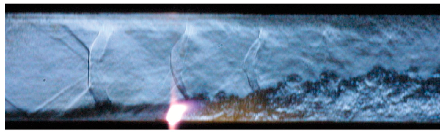
Figure 4.
(a) Effects of net input energy with residual H2 combustion heat on the ignition limit for φ = 0.4, [48], reprinted from [48] with permission from AIAA; (b) pressure effect of the plasma torch depending on plasma power (the figure is courtesy of Dr. K. Takita).

Figure 6.
The OH PLIF images overlapped with a typical schlieren image of the same flow condition: (a) without plasma; (b) in the presence of the plasma [87], (the figure is courtesy of Dr. Hyungrok Do).
Figure 6.
The OH PLIF images overlapped with a typical schlieren image of the same flow condition: (a) without plasma; (b) in the presence of the plasma [87], (the figure is courtesy of Dr. Hyungrok Do).

Figure 7.
Schematics of the PWT-50H test section. The location of the plasma-injection modules is shown by a rectangle in the top wall.
Figure 7.
Schematics of the PWT-50H test section. The location of the plasma-injection modules is shown by a rectangle in the top wall.

Figure 8.
(a) Schematic drawing of two basic layouts for the fuel injectors and electrode arrangement; (b) 3D view of ceramic insertion used during testing.
Figure 8.
(a) Schematic drawing of two basic layouts for the fuel injectors and electrode arrangement; (b) 3D view of ceramic insertion used during testing.
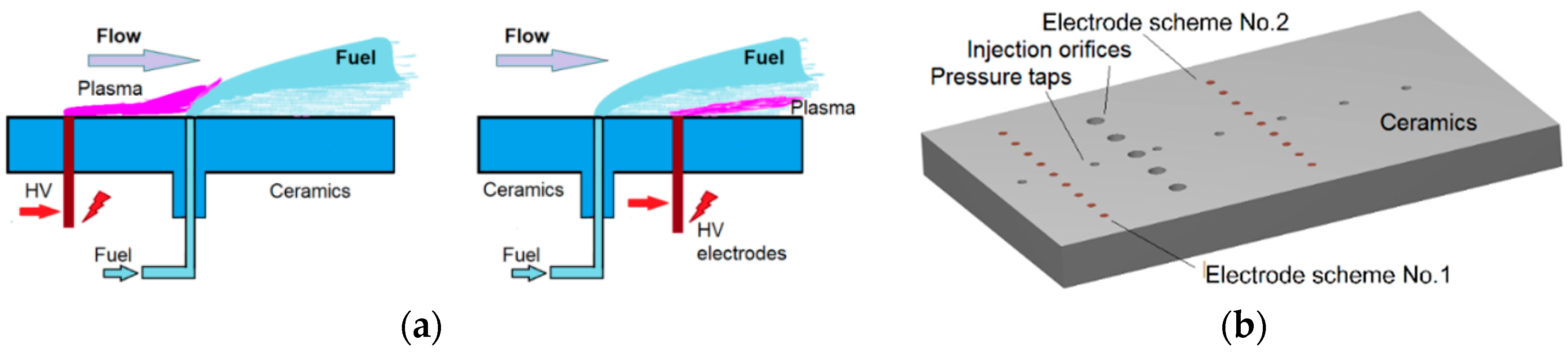
Figure 9.
Composite optical emission spectrum obtained from the ethylene-airflow-plasma interaction region. Major emission lines and bands are labeled. Reprinted from [28] with permission from Elsevier.
Figure 9.
Composite optical emission spectrum obtained from the ethylene-airflow-plasma interaction region. Major emission lines and bands are labeled. Reprinted from [28] with permission from Elsevier.
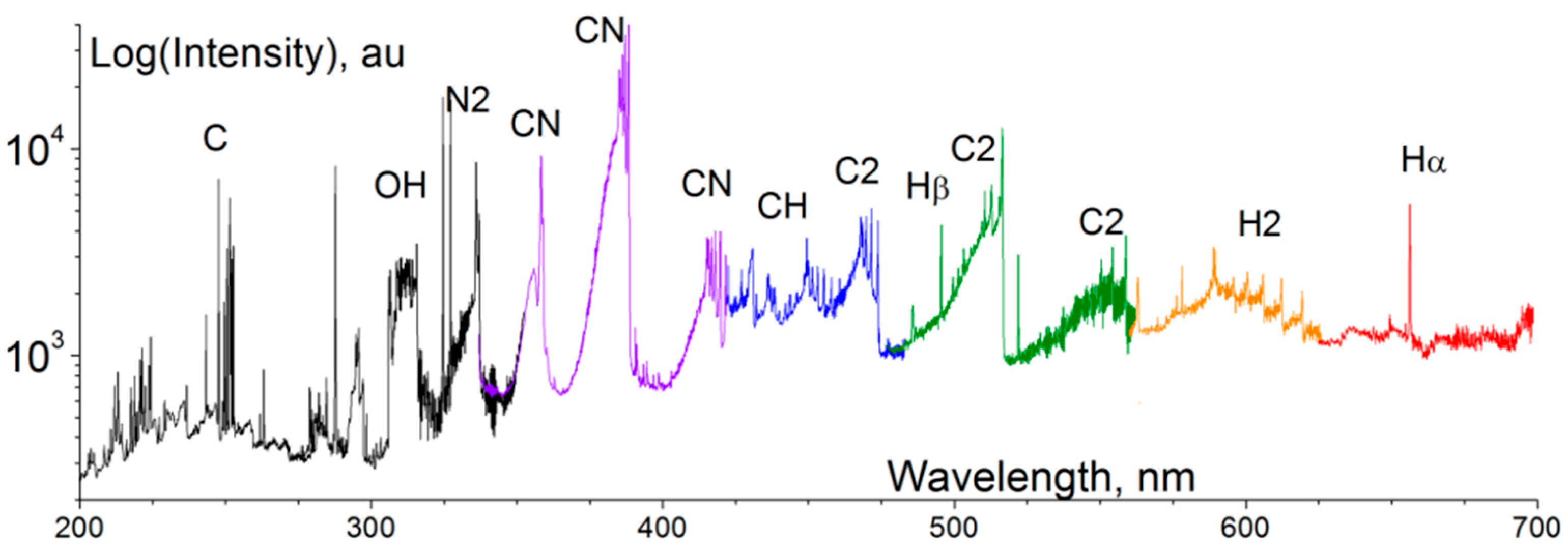
Figure 10.
Normalized pressure distribution, scheme 1 vs. scheme 2: (a) along the test section at variation of fuel mass flow rate; (b) at two locations vs. fuel mass flow rate. For (a) the legend “Flow” means “no fuel/no plasma” case, “Dis” means “no fuel/plasma on” case.
Figure 10.
Normalized pressure distribution, scheme 1 vs. scheme 2: (a) along the test section at variation of fuel mass flow rate; (b) at two locations vs. fuel mass flow rate. For (a) the legend “Flow” means “no fuel/no plasma” case, “Dis” means “no fuel/plasma on” case.

Figure 11.
Schlieren image illustrating the flow structure in the test section at combustion, scheme 1, ṁC2H4 = 1.3 g/s.
Figure 11.
Schlieren image illustrating the flow structure in the test section at combustion, scheme 1, ṁC2H4 = 1.3 g/s.

Figure 12.
Geometrical configuration of the SBR-50 test section.

Figure 13.
(a) Schematics of fuel injector and electrode arrangement; (b) photo of PIMs in the test section.
Figure 13.
(a) Schematics of fuel injector and electrode arrangement; (b) photo of PIMs in the test section.

Figure 14.
Typical wall pressure distributions for three cases: (a) strong combustion; (b) weak combustion; (c) partial fuel oxidation.
Figure 14.
Typical wall pressure distributions for three cases: (a) strong combustion; (b) weak combustion; (c) partial fuel oxidation.

Figure 15.
Images of the combustion zone for two cases: (a) strong combustion; (b) partial fuel oxidation. Flow is from left to right.
Figure 15.
Images of the combustion zone for two cases: (a) strong combustion; (b) partial fuel oxidation. Flow is from left to right.

Figure 16.
(a) FastCam frame showing the discharge morphology; (b) 3D reconstruction of the plasma filament shape. Reprinted from [110] with permission from authors.
Figure 16.
(a) FastCam frame showing the discharge morphology; (b) 3D reconstruction of the plasma filament shape. Reprinted from [110] with permission from authors.

Figure 17.
Schlieren image of the interaction zone: plasma on–fuel on [109].
Figure 17.
Schlieren image of the interaction zone: plasma on–fuel on [109].

Figure 18.
Pressure increase vs. fuel mass flow rate for three PIMs scheme: x = 200 mm.

Figure 19.
Mach number distribution over the test section of SBR-50 at plasma-assisted combustion: P0 = 1.8 bar, T0 = 290 K, ṁC2H4 = 5.4 g/s, Wpl = 13.6 kW.
Figure 19.
Mach number distribution over the test section of SBR-50 at plasma-assisted combustion: P0 = 1.8 bar, T0 = 290 K, ṁC2H4 = 5.4 g/s, Wpl = 13.6 kW.

Figure 20.
Result of simulation [124]: Richtmyer–Meshkov instability intensification by pulse-periodic heat source: (a) no heat source; (b) heat source on at x = 13 cm, y = 13 cm. Reprinted from [124] with permission from authors.

Figure 21.
Phase-averaged streamwise planar images demonstrating effect of excitation azimuthal mode on LSS development for (a) baseline; (b) axisymmetric; (c) helical; and (d) flapping forcing modes [128]. Reprinted from [127] with permission from AIAA.

Figure 22.
High speed imaging of interaction of electrical discharge with the external magnetic field of B = 0.05 T in air flow of 10 m/s (frame rate is 1.2 kHz); the external electrode is the cathode, current I = 1 A. Reprinted from [136] with permission from authors.
Figure 22.
High speed imaging of interaction of electrical discharge with the external magnetic field of B = 0.05 T in air flow of 10 m/s (frame rate is 1.2 kHz); the external electrode is the cathode, current I = 1 A. Reprinted from [136] with permission from authors.

Figure 23.
Schlieren images of gasdynamic instabilities developed due to pulse discharge generation in ambient air. (a) Time delay t ≈ 1 µs; (b) time delay t = 100 µs; (c) time delay t = 1 ms. “SW”—position of shock wave; “DCh”—interface of residual thermal cavity expanded after the electrical discharge.

Figure 24.
Density distribution at jet generation. 3D RANS simulation [139], gray scale in kg/m3, symmetry plane: (a) 50 μs; (b) 500 μs; (1) main jet from the external bend; (2) main jet from the central bend, and (3) fast disturbance from the central bend. Experiment (schlieren images): (c) 40 μs; (d) 540 μs.

Figure 25.
Test on the mixing efficiency measurement: (a) experimental arrangement of the PBF measurements in high-speed flow; (b) spectra of the probe plasma in M = 2 flow at main discharge switched on and off.
Figure 25.
Test on the mixing efficiency measurement: (a) experimental arrangement of the PBF measurements in high-speed flow; (b) spectra of the probe plasma in M = 2 flow at main discharge switched on and off.

Figure 26.
2D dynamics of pressure distribution over upper wall at (a) ignition and (b) flame extinction.
Figure 26.
2D dynamics of pressure distribution over upper wall at (a) ignition and (b) flame extinction.

Figure 27.
(a) Discharge power and wall pressure traces during combustion instability, ṁC2H4 = 5.9 g/s; low-pass cutoff filter is applied; (b) 2D dynamics of pressure distribution, time is counted from plasma on.
Figure 27.
(a) Discharge power and wall pressure traces during combustion instability, ṁC2H4 = 5.9 g/s; low-pass cutoff filter is applied; (b) 2D dynamics of pressure distribution, time is counted from plasma on.

Figure 28.
Discharge images at (a) weak combustion case and at (b) strong combustion with separation. Flow is from left to right. Exposure 1 µs, frame x-length is about 120 mm.
Figure 28.
Discharge images at (a) weak combustion case and at (b) strong combustion with separation. Flow is from left to right. Exposure 1 µs, frame x-length is about 120 mm.

Figure 29.
Diagram illustrating a feedback loop of combustion instability development. Small vertical arrows show an increase (up) or reduction (down) of parameter values. Larger inclined arrows show the sequence of processes involved.
Figure 29.
Diagram illustrating a feedback loop of combustion instability development. Small vertical arrows show an increase (up) or reduction (down) of parameter values. Larger inclined arrows show the sequence of processes involved.

Figure 30.
Data on fast pressure measurements (Kulite™ sensors): (a) time series; (b) time-resolved traces; (c) tpectra of pressure oscillations.
Figure 30.
Data on fast pressure measurements (Kulite™ sensors): (a) time series; (b) time-resolved traces; (c) tpectra of pressure oscillations.


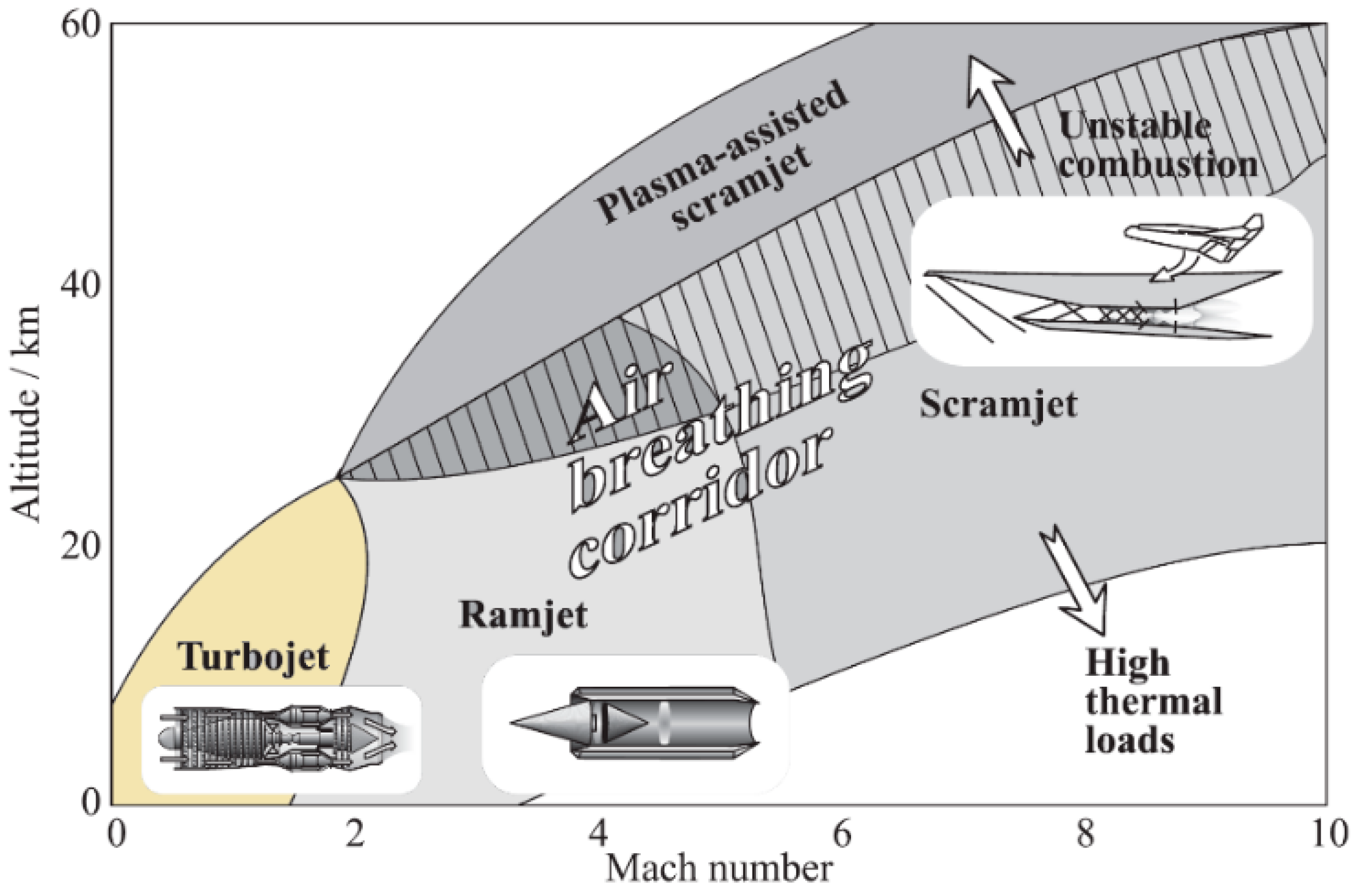
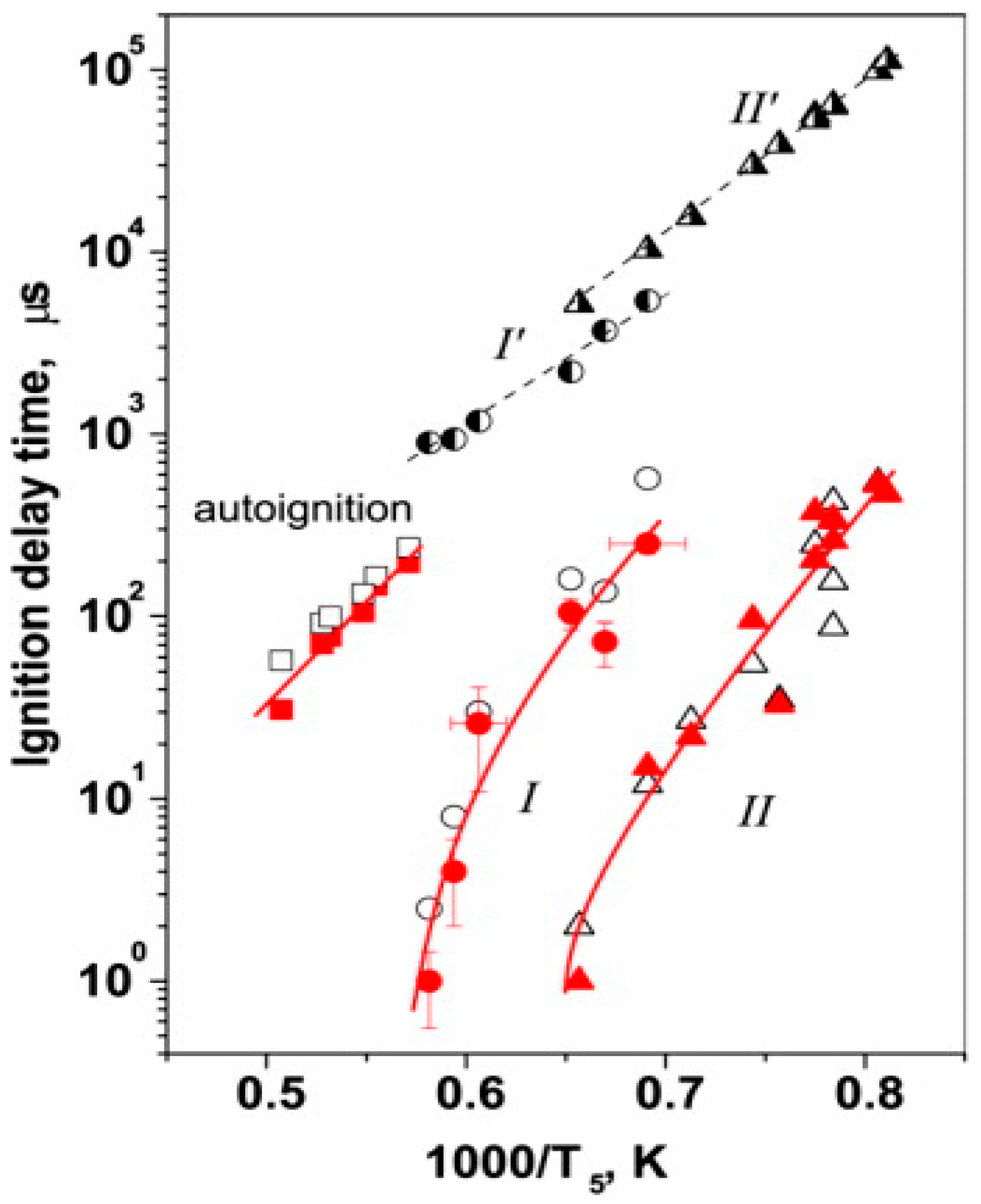
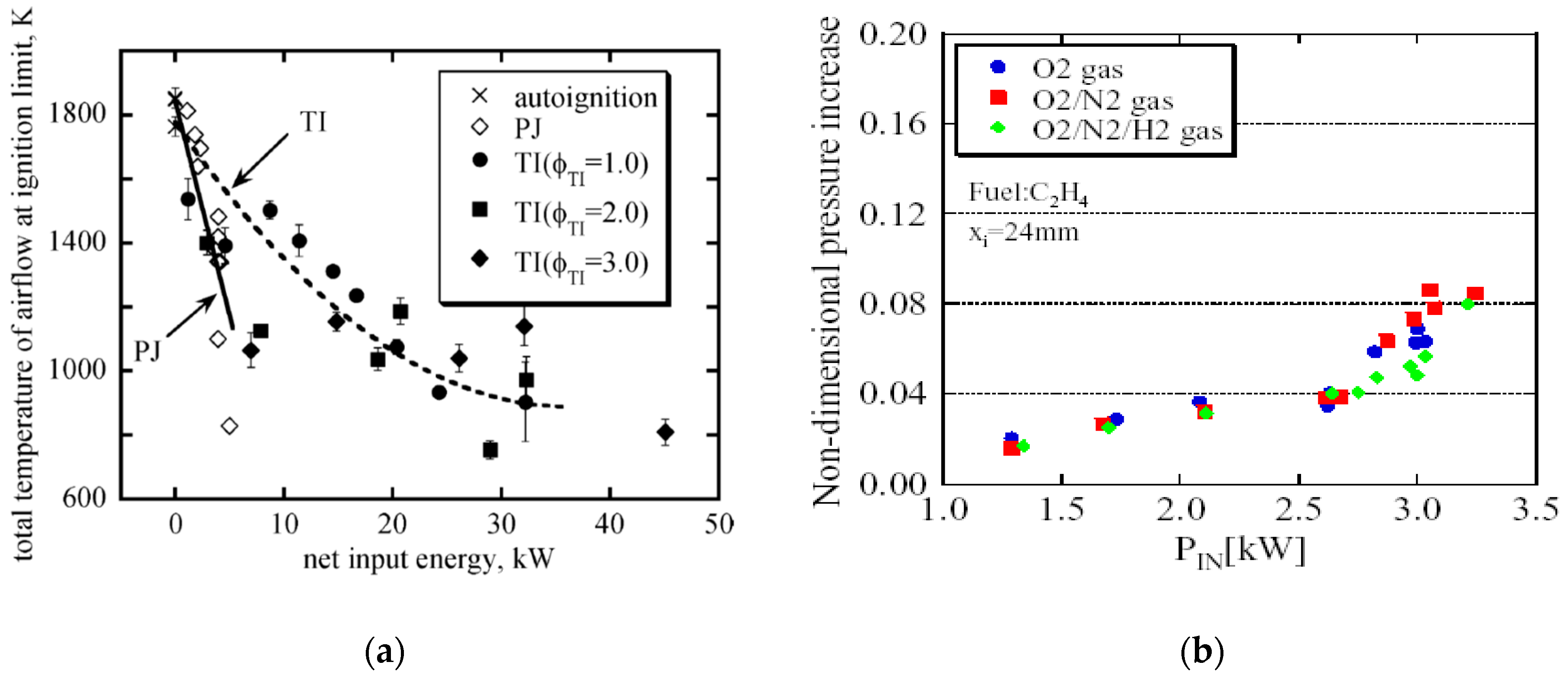
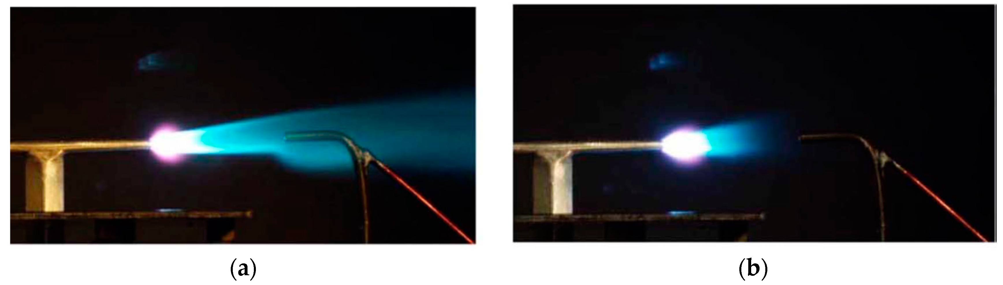
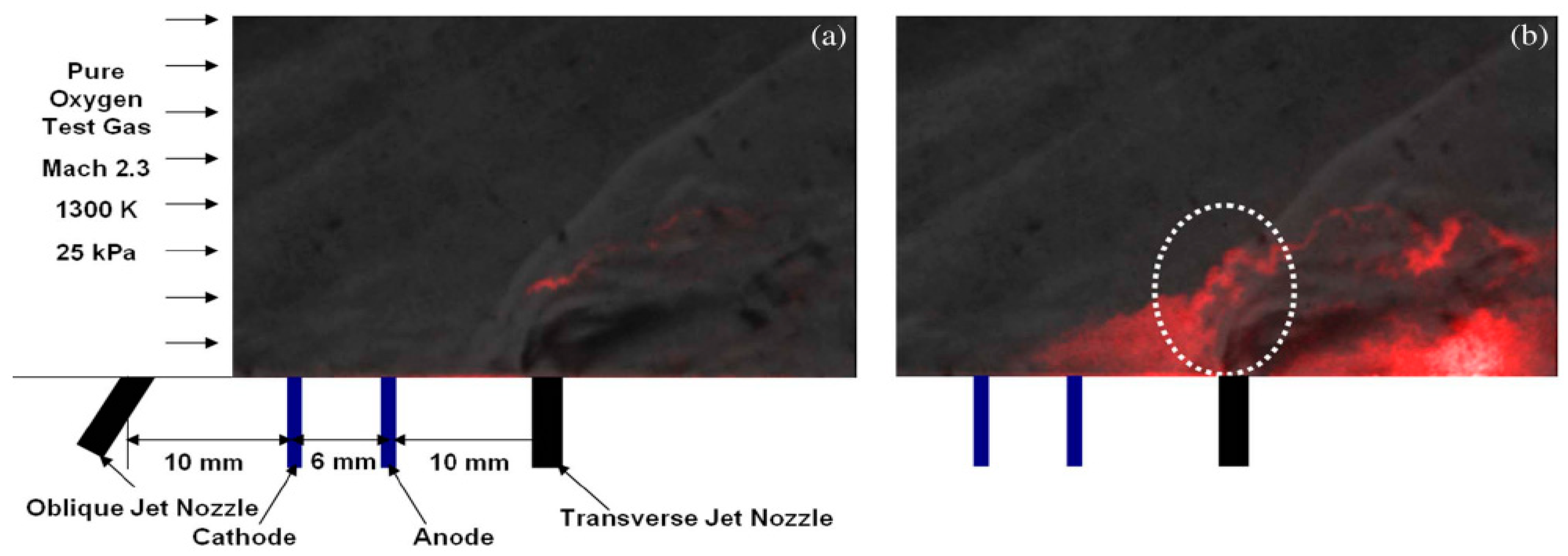
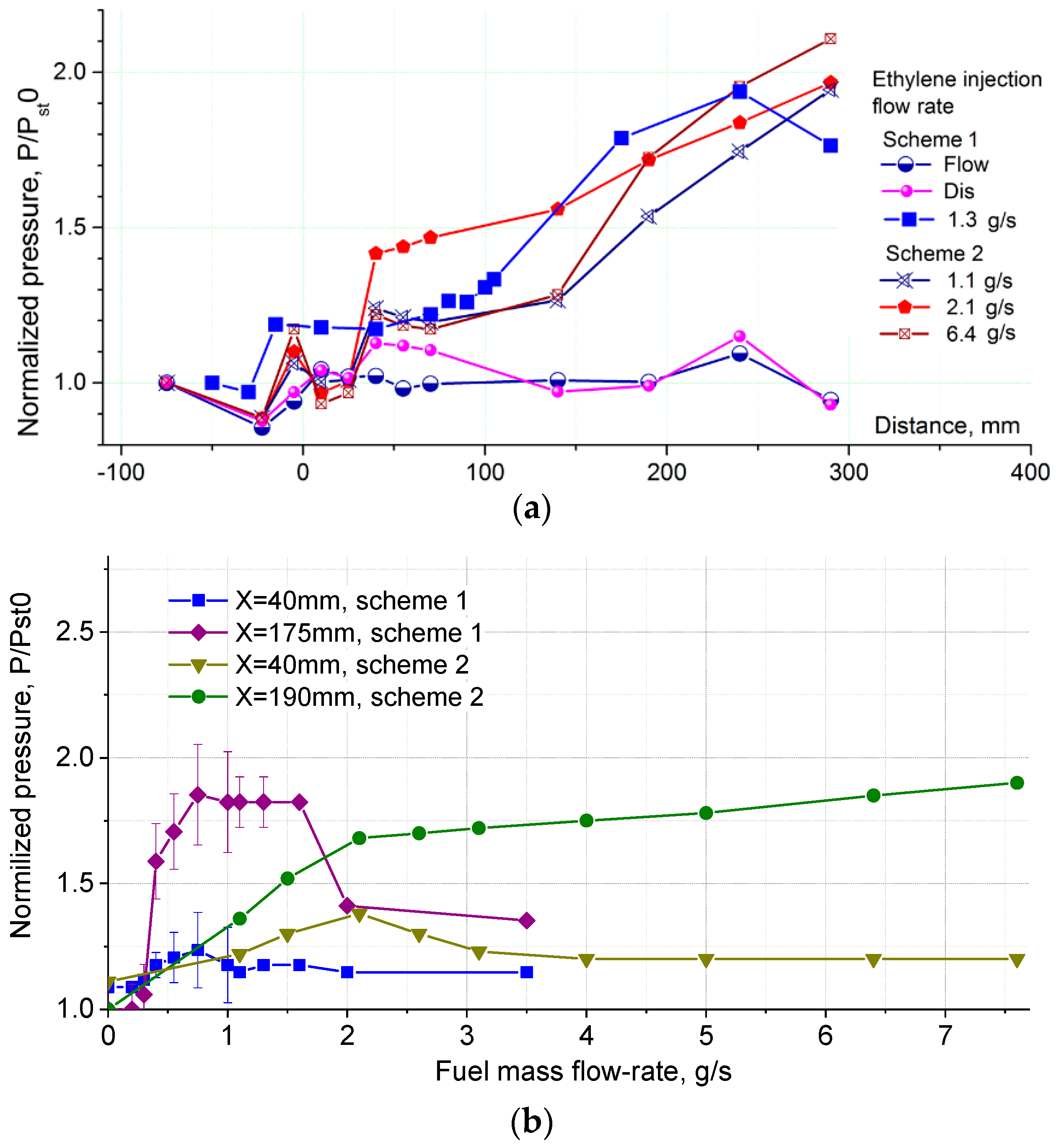
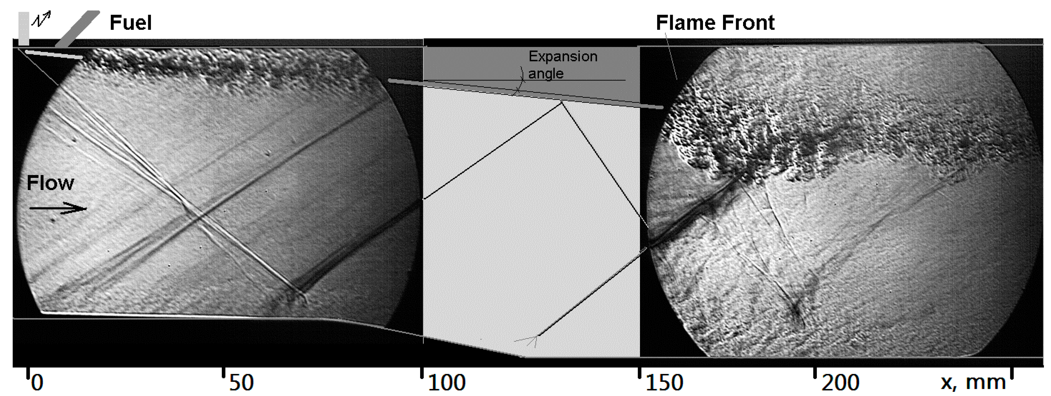
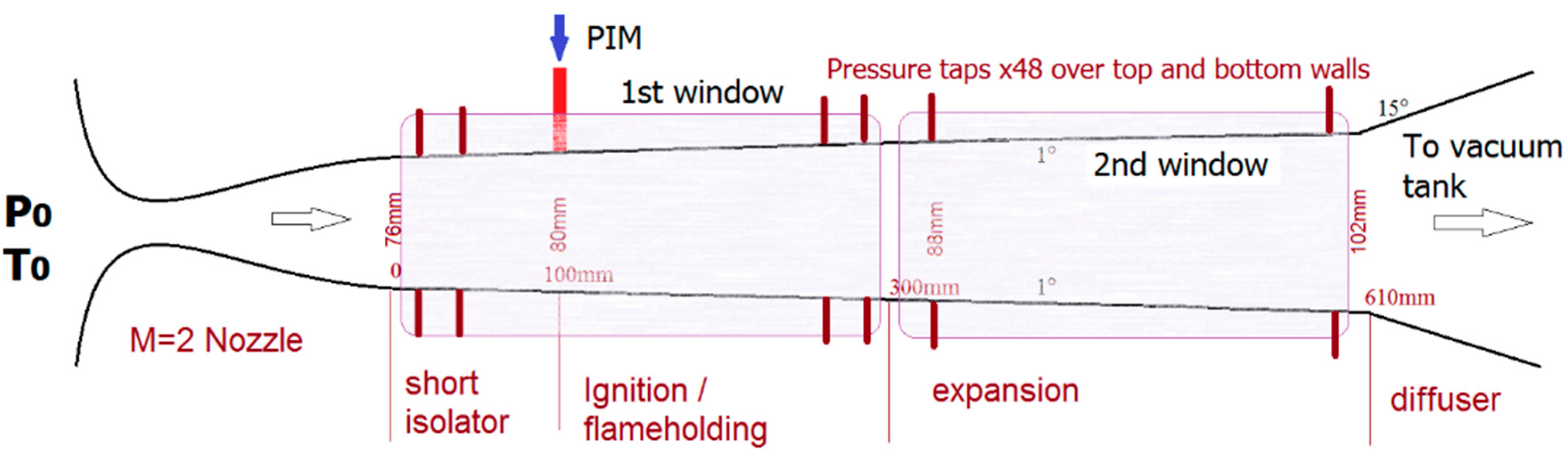
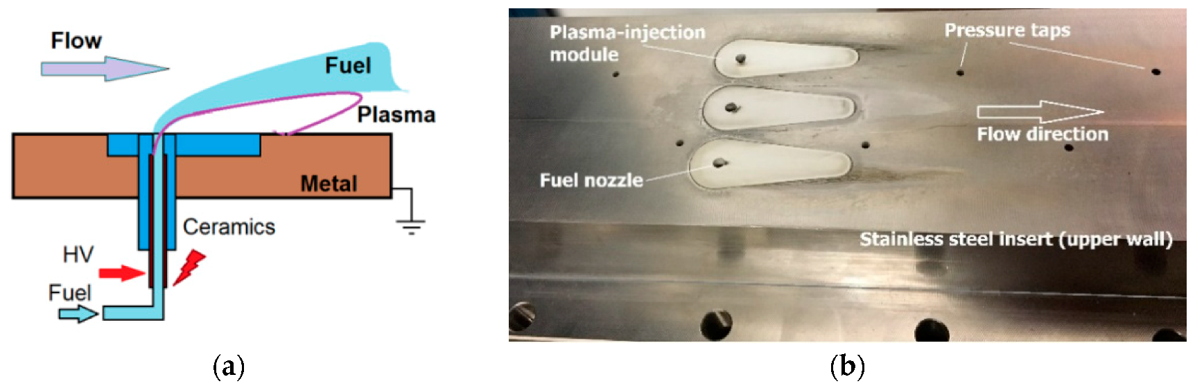
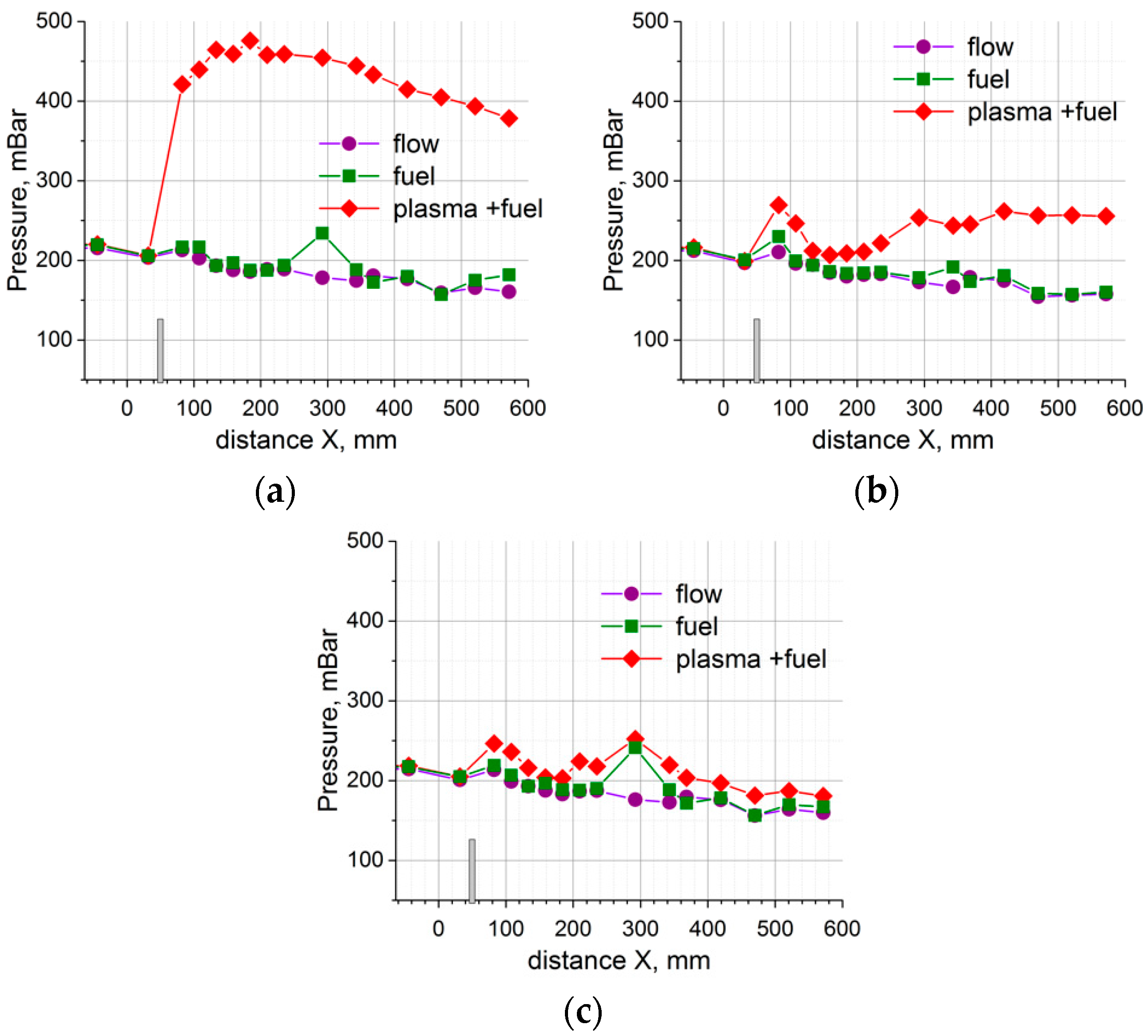
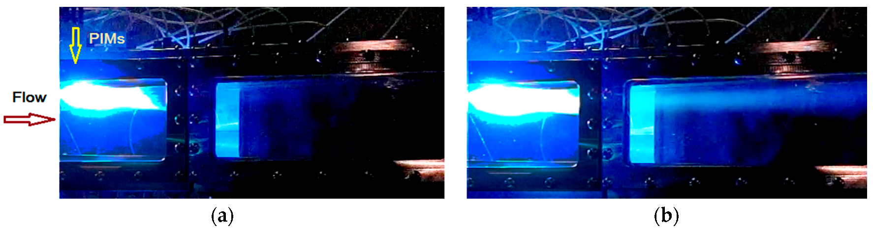
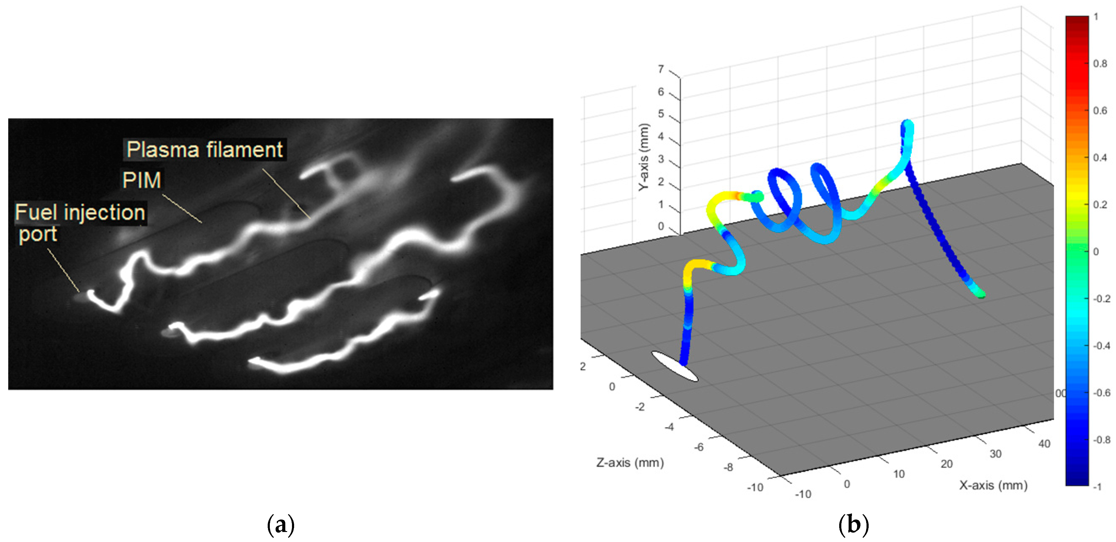
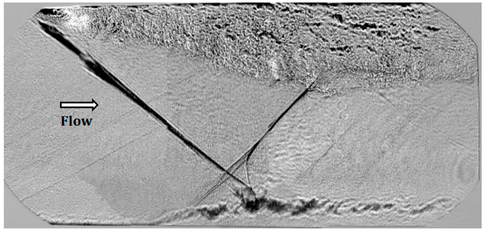
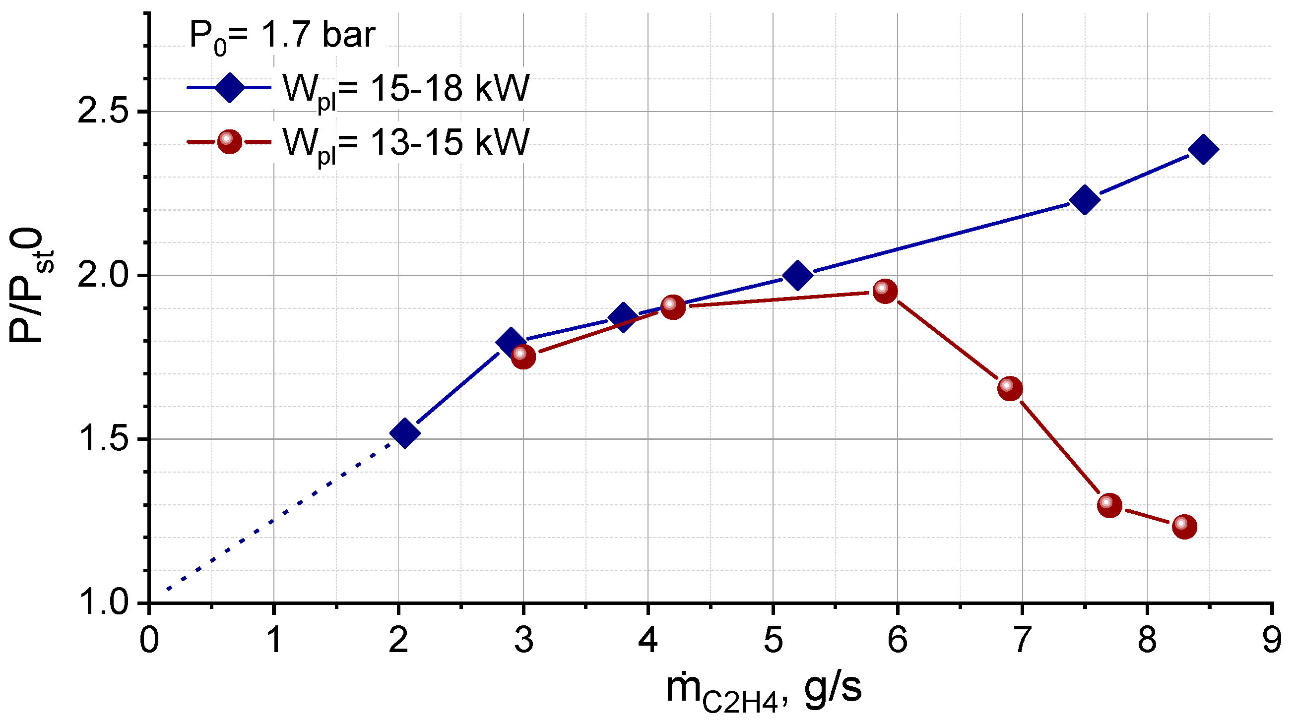
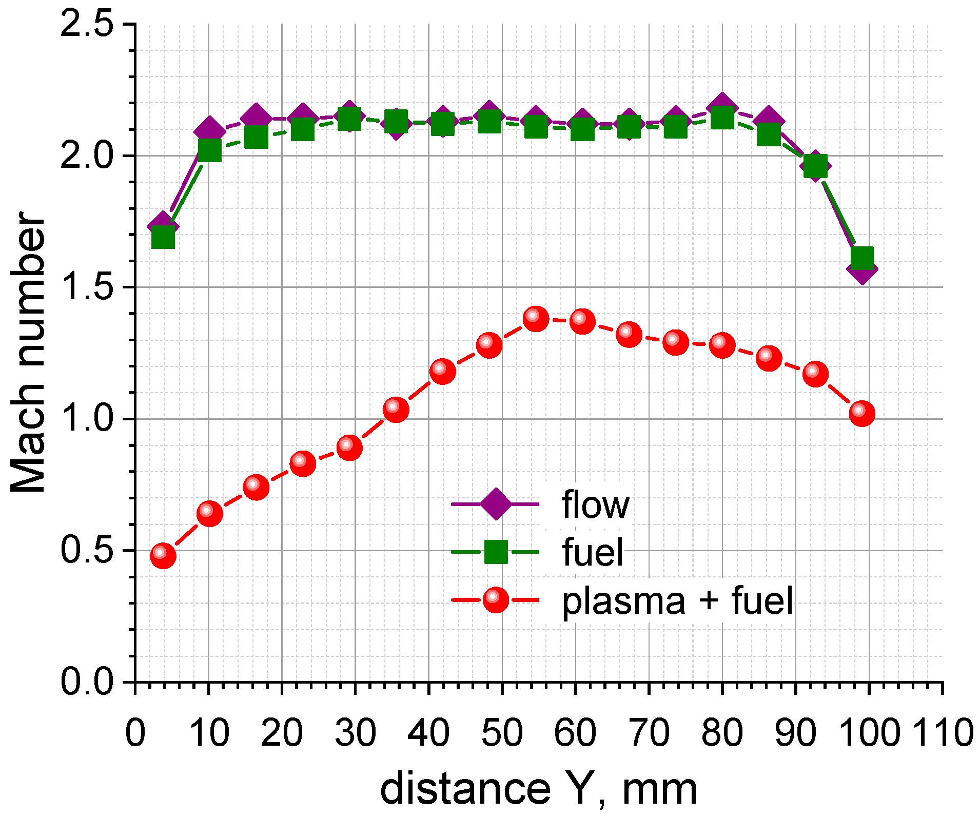
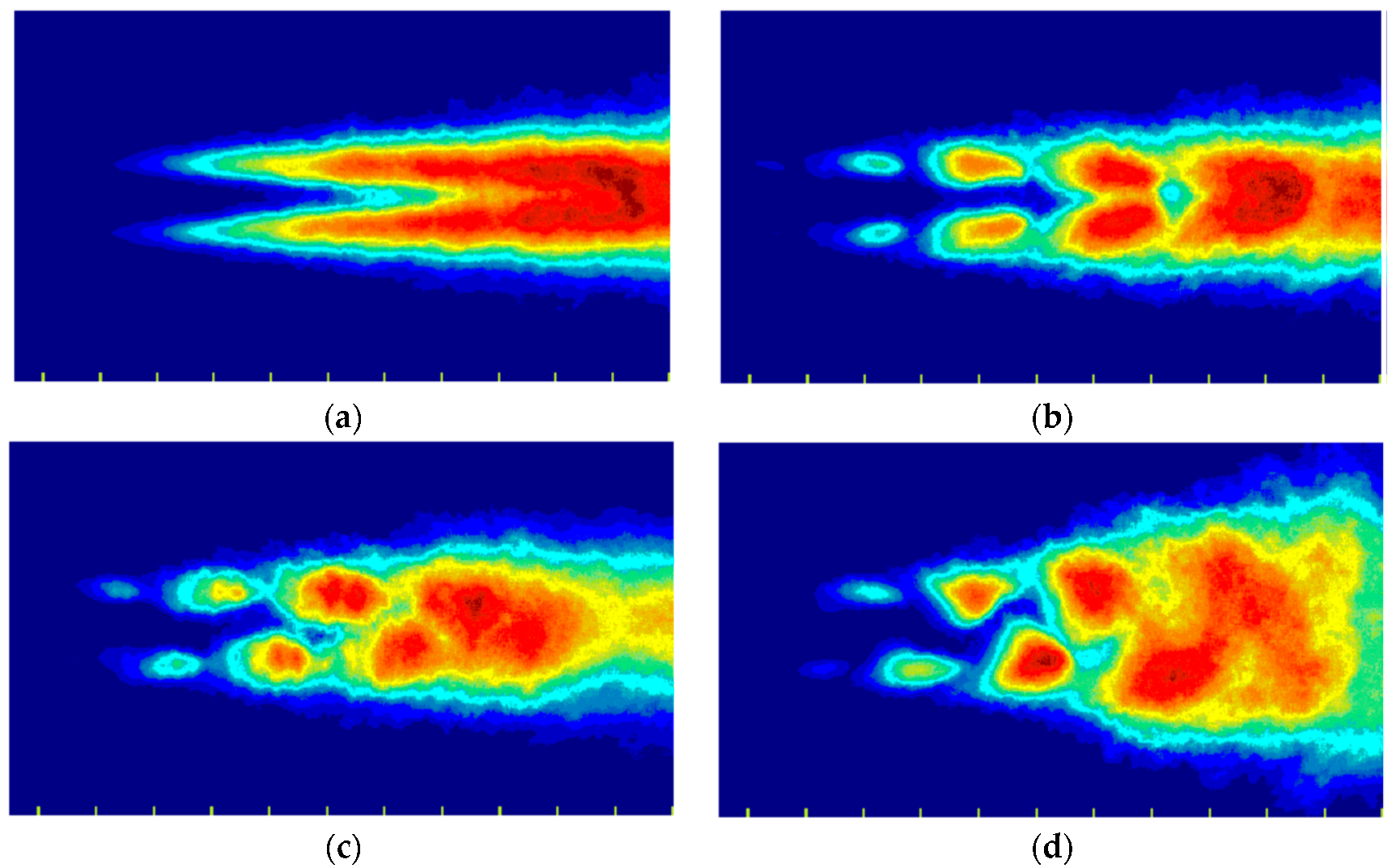
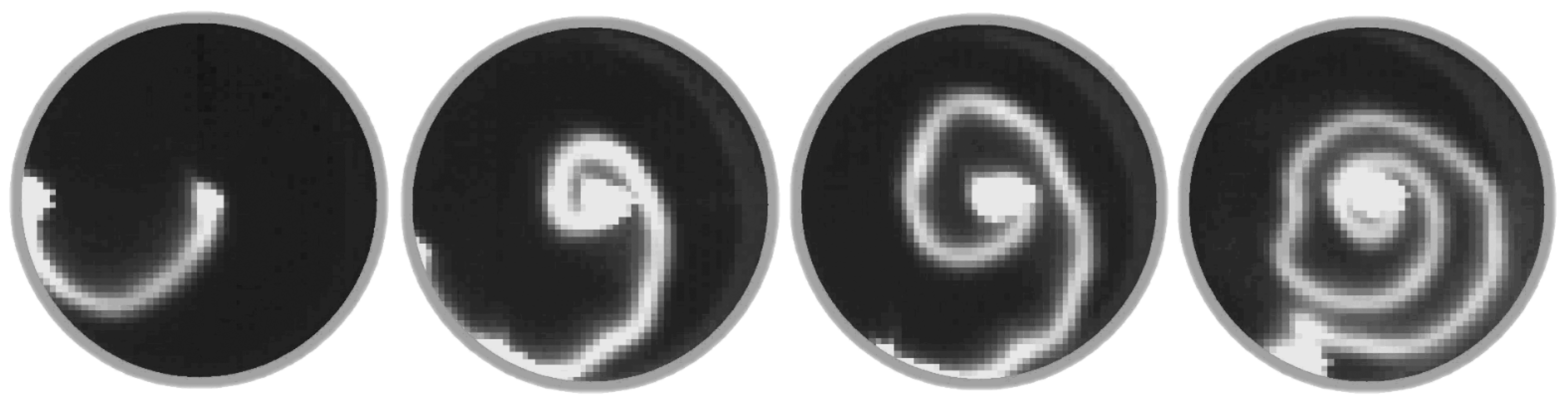
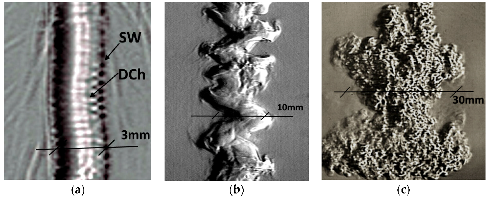
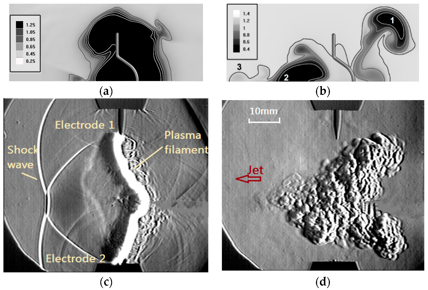
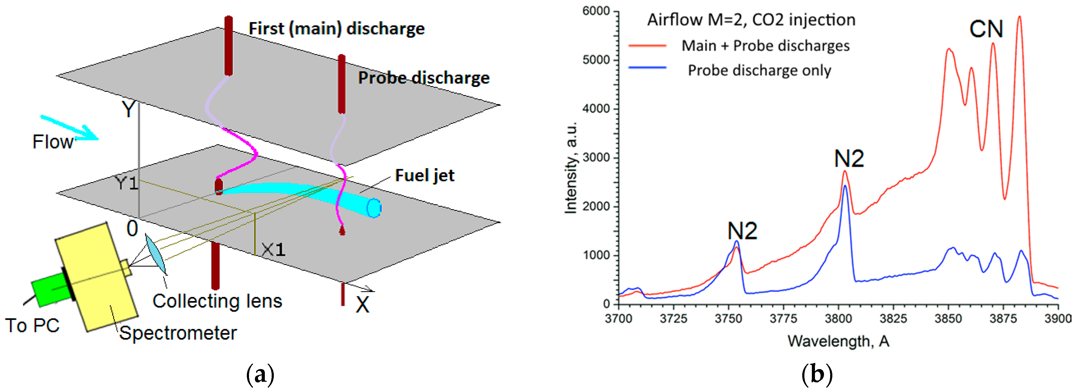
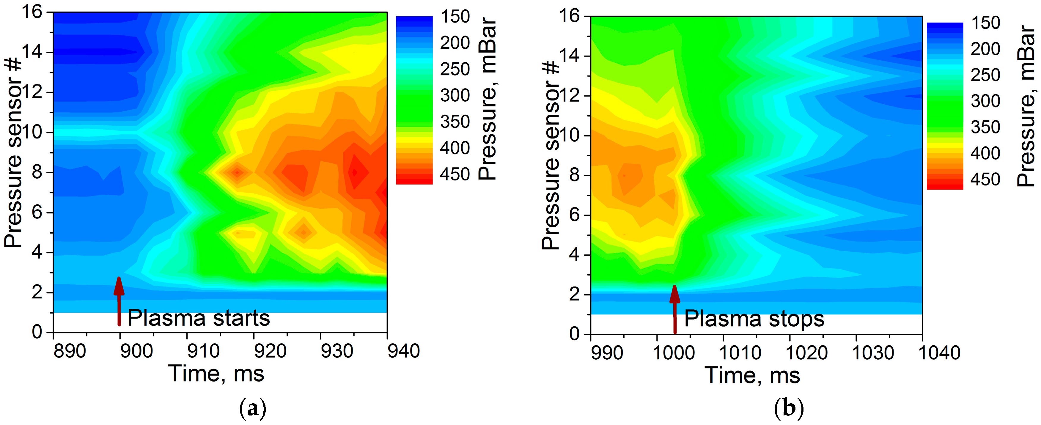
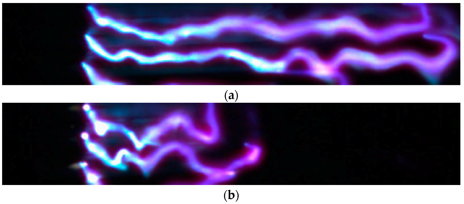
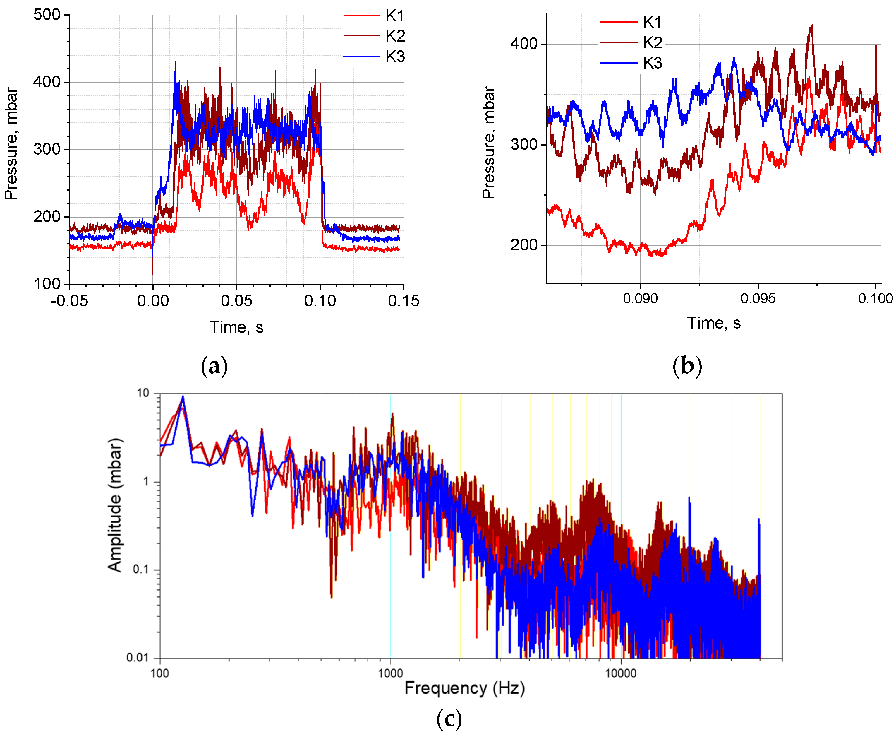
Table 1.
Brief characterization of electric discharges used for PAC and flow control [67].
Table 1.
Brief characterization of electric discharges used for PAC and flow control [67].
| Discharge Type | Typ. Power | Benefits | Disadvantages | Refs. |
|---|---|---|---|---|
| Longitudinal surface arc, DC | 1–10 kW | High temperature | Location in boundary layer, electrodes erosion, low efficiency | [69,70,71] |
| Transverse Near-Surface Quasi-DC | 1–30 kW | Mixing, long time of interaction, high temperature | Electrodes erosion, low volume of treatment | [31,69] |
| Glow discharge | 0.1–1 kW, continuous | Large volume, effective in radicals generation | Operation at low density | [72,73] |
| Volumetric arc | 1–10 kW | High temperature, long time of interaction | High level of required power | [59,60] |
| Plasma torch | 1–30 kW | High temperature, fuel through plasma | Plasma inside the torch device, low efficiency | [1,40,41,45,47,51] |
| RF filamentary | 0.1–1 kW | High speed of penetration, mixing, single-electrode | Low power deposition, unpredictable position | [52,53,54,55] |
| Microwave | 1–10 kW 0.1–10 J/pulse | Initiator or electrodeless, high efficiency in radicals generation | Complex equipment, large breakdown threshold at high pressure, sensitive to flow | [18,52,56,58] |
| DBD/Corona | 1 W/cm2 | Effective in radicals generation | Location in near-surface layer, low density of energy deposition | [34,74,75] |
| Nanosecond pulse discharge | 0.01–1 J/pulse | Effective in radicals generation, high-speed of penetration | Low-pressure application for homogeneous appearance | [12,14,68,76] |
| Short-pulse long spark | 1–100 J/pulse | High density of energy deposition, effective mixing | Short time of interaction, high-voltage | [77,78] |
| Laser spark | Wide range | High density of energy deposition. | Small volume of interaction, low energetic efficiency of lasers | [79,80,81,82] |
© 2018 by the author. Licensee MDPI, Basel, Switzerland. This article is an open access article distributed under the terms and conditions of the Creative Commons Attribution (CC BY) license (http://creativecommons.org/licenses/by/4.0/).
Share and Cite
MDPI and ACS Style
Leonov, S.B. Electrically Driven Supersonic Combustion. Energies 2018, 11, 1733. https://doi.org/10.3390/en11071733
AMA Style
Leonov SB. Electrically Driven Supersonic Combustion. Energies. 2018; 11(7):1733. https://doi.org/10.3390/en11071733
Chicago/Turabian StyleLeonov, Sergey B. 2018. "Electrically Driven Supersonic Combustion" Energies 11, no. 7: 1733. https://doi.org/10.3390/en11071733
Note that from the first issue of 2016, this journal uses article numbers instead of page numbers. See further details here.