Review of Electromagnetic Vibration in Electrical Machines


Department of Mechanical Engineering, Tsinghua University, Beijing 100084, China
*
Author to whom correspondence should be addressed.
Energies 2018, 11(7), 1779; https://doi.org/10.3390/en11071779
Submission received: 5 June 2018
/
Revised: 27 June 2018
/
Accepted: 27 June 2018
/
Published: 6 July 2018
(This article belongs to the Special Issue Control and Nonlinear Dynamics on Energy Conversion Systems)
Abstract
:Electrical machines are important devices that convert electric energy into mechanical work and are widely used in industry and people’s life. Undesired vibrations are harmful to their safe operation. Reviews from the viewpoint of fault diagnosis have been conducted, while summaries from the perspective of dynamics is rare. This review provides systematic research outlines of this field, which can help a majority of scholars grasp the ongoing progress and conduct further investigations. This review mainly generalizes publications in the past decades about the dynamics and vibration of electrical machines. First the sources of electromagnetic vibration in electrical machines are presented, which include mechanical and electromagnetic factors. Different types of air gap eccentricity are introduced and modeled. The analytical methods and numerical methods for calculating the electromagnetic force are summarized and explained in detail. The exact subdomain analysis, magnetic equivalent circuit, Maxwell stress tensor, winding function approach, conformal mapping method, virtual work principle and finite element analysis are presented. The effects of magnetic saturation, slot and pole combination and load are discussed. Then typical characteristics of electromagnetic vibration are illustrated. Finally, the experimental studies are summarized and the authors give their thoughts about the research trends.
1. Introduction
With the continuous development of the economy, electrical machines have been widely used in industries and people’s lives. Ever higher performance requirements are being put forward for electrical machines. The magnetic field can interact with mechanical structures, which will produce unbalanced magnetic forces and excite harmful vibrations. These forces may have significant effects on the dynamic behavior and noise of rotors. The vibration and noise range of electrical machines is one of the important indicators in the manufacture. National standards also clearly prescribe the vibration and noise limits of rotating electrical machines. Vibration and noise will affect people’s daily life and severe vibration will cause significant economic losses. Furthermore, the vibrations of electrical machines may decrease the efficiency of the energy conversion because the vibration and possible related temperature rise are unwanted energy losses for the system.
The vibrations of electrical machines can be divided into three categories: mechanical vibrations, electromagnetic vibrations and aerodynamic vibrations. Benefitting from the continuous improvement of design and manufacturing level, the performance of electrical machines has been greatly improved and their volume has become very small. For the widely used small and medium-sized electrical machines, electromagnetic vibrations are the main type. With the growth of living standards, people will pay more and more attention to the vibration of electrical machines. Investigating the vibration mechanism can be helpful for the design of electrical machines. Therefore, the study of the electromagnetic vibration of electrical machines has practical significance.
Electromagnetic vibrations are usually generated by the distorted air-gap field of an eccentric rotor in electrical machines. The uneven air-gap is directly related to the eccentricity, which is common in rotating electrical machines. Eccentricity can be caused by several reasons, such as relative misalignment of the rotor and stator in the fixing stage, misalignment of the load axis and rotor shaft, elliptical stator inner cross section, wrong placement or rubbing of ball bearings, mechanical resonance, and unbalanced loads [1,2]. Eccentricities can be further subdivided into two categories: circumferential unequal air gaps and axial unequal air gaps. The former can be grouped into static eccentricity and dynamic eccentricity. In the case of static eccentricity, the rotor rotates around its own geometric axis, which is not the geometric axis of the stator. In the case of dynamic eccentricity, the rotor is not concentric and rotates around the geometric axis of the stator. In reality, both static eccentricity and dynamic eccentricity tend to coexist. An inherent static eccentricity exists, even in newly manufactured machines, due to the build-up of tolerances during the manufacturing and assembly procedure, as has been reported in [3]. Unequal air gaps cause unbalanced magnetic forces (UMFs) [4] on the rotor, which lead to mechanical stress on some part of the shaft and bearing. After prolonged operation, these factors cause broken mechanical parts or even the stator to rub the rotor, causing major breakdowns of the machines [5].
The calculation of UMF is essential for the analysis of vibrations and the optimal design of electrical rotating machinery. Two common approaches are the analytical method and the finite element method (FEM). Although the FEM has been widely applied to study the UMF [6,7], the analytical method still receives much attention because insights into the origins and pivotal factors in the production of UMF is provided by this method. Earlier publications focused primarily on the theoretical formulation of UMF and linear equations were mainly adopted. Werner [8] established a dynamic model for an induction motor with eccentric excitation by taking radial electromagnetic stiffness into account. The linear expressions are convincing only for cases where the eccentricity is small enough. Therefore linear approaches are far from industrial applications. The nonlinear relationship between the UMF and eccentricity was pointed out in [9]. After that, many researchers have introduced nonlinear approaches to determine UMF in the last two decades. For instance, winding function analysis [10], conformal mapping method [11], energy conservation law [12], magnetic equivalent circuit method [13] and exact subdomain model [14] were all applied to investigate the magnetic field distribution and UMF for electrical machines with non-uniform air-gaps. The most commonly adopted analytical method is the air-gap permeance approach [15,16]. An analytical expression of UMF for different pole-pairs was obtained by expressing the air-gap permeance as a Fourier series in [15]. A calculation model for UMF was presented in [16] based on the actual position of the rotor inside the stator.
It should be noted that the design and modeling of electrical machine systems are a multidisciplinary problem because the electromagnetics, structural mechanics and heat transfer are involved, the design optimization process becomes more and more complex [17]. Therefore it is significant to pursue optimal system performance rather than optimal components such as motors or controllers, because assembling individually optimized components into a system cannot ensure an optimal performance for the whole system [18,19]. The problem is really a challenge for both the research and industrial communities since it includes not only theoretical multidisciplinary design and analysis (such as electromagnetic, thermal, mechanical analysis and power electronics) but also practical engineering manufacturing of the system. Lei et al. [20] developed a robust approach for the system-level design optimization of the electrical machine system. Khan et al. [21] presented a multilevel design optimization framework to improve the efficiency of the proposed method by combining it with several techniques, such as design of experiments and approximate models.
The electromagnetic vibration of electrical machines has always been a hot topic in the mechanical discipline and electrical discipline fields, and there exist rich research results. The existing reviews of electromagnetic vibration are basically summarized from the view of fault diagnosis [22,23,24,25,26,27], and summaries from the perspective of dynamics are rather insufficient. With the continuous progress of research, some new technologies and methods are emerging. It is necessary to generalize the latest research progress of electromagnetic vibration from the perspective of dynamics and vibration to avoid repetitive work. In addition, a review which provides systematic research outlines and references can be beneficial for the majority of scholars in this field to promote the ongoing progress and development of the investigations.
Different from the condition monitoring standpoint, this review is mainly concerned with the dynamic issues of electromagnetic vibrations in electrical machines. First, the vibration sources, which include the mechanical and electromagnetic aspects, are summarized in Section 2. Then Section 3 presents in detail different analytical and numerical calculation methods for the electromagnetic force. After that, the electromagnetic vibration characteristics and experimental investigations are demonstrated in Section 4. Finally Section 5 summarizes the authors’ thoughts about the trends and prospects of this research.
2. Sources of Electromagnetic Vibration
Under ideal conditions, the air gap between the stator and rotor is uniform and the magnetic circuit is symmetrical. The rotor rotates in the uniform magnetic field and the total force of the radial electromagnetic force is zero. If mechanical or electromagnetic factors make the radial force around the rotor circumference uneven, it will produce an electromagnetic force which is also known as the unbalanced magnetic force (UMF). UMF will cause undesired electromagnetic vibration and noise, exacerbate the bearing wear, influence the stability of the rotor system and even produce rubbing between the rotor and stator. The potential hazards are prominent. Therefore, the investigation of this coupling interaction is necessary and important.
In essence, the main source of electromagnetic vibration is the asymmetry of the magnetic circuit in the electrical machine. The misalignment between the stator and rotor is the most common cause of UMF. Furthermore, the uneven magnetization of the material and the improper winding can also generate UMF. Generally speaking, the electromagnetic sources can be divided into mechanical factors and electromagnetic factors.
2.1. Mechanical Sources
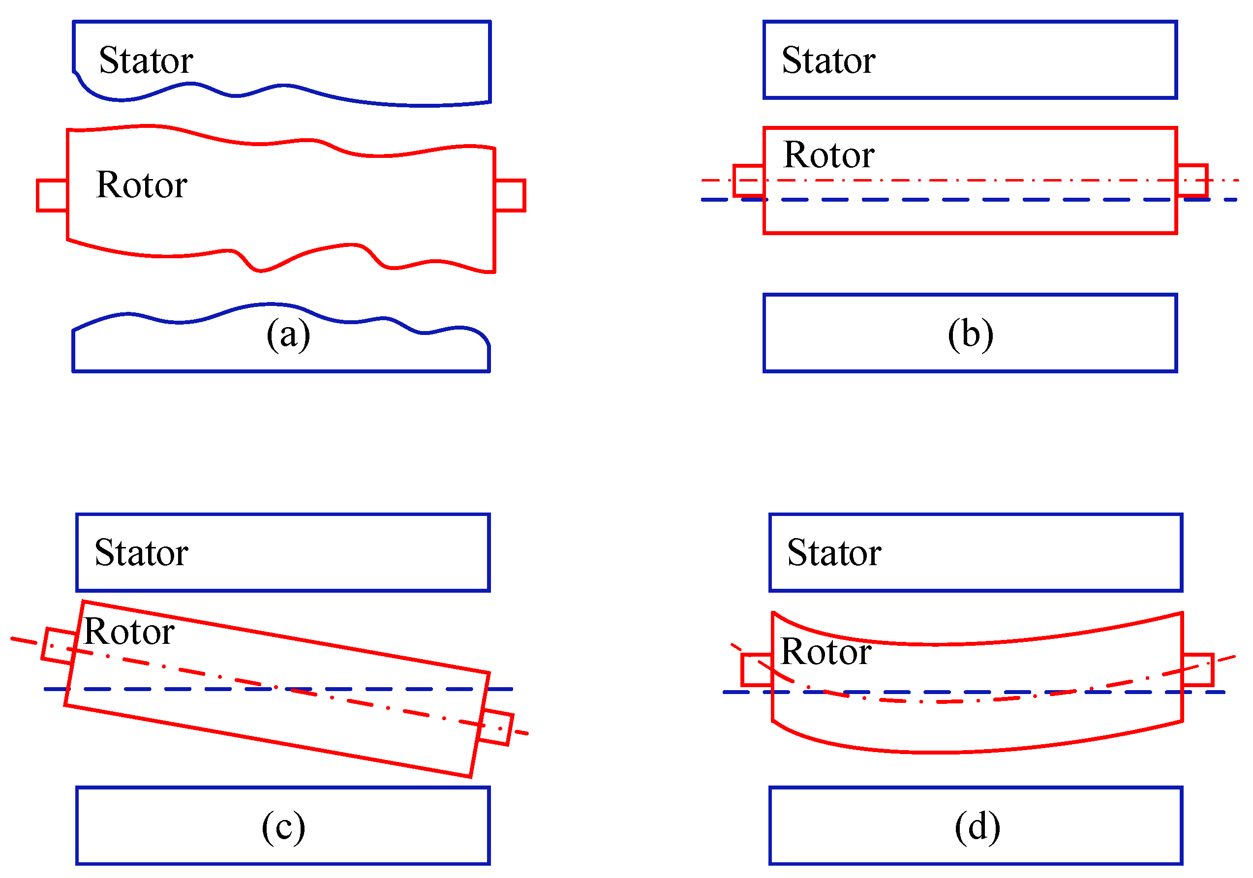
The mechanical causes of the electromagnetic force are mainly the air gap eccentricity between the stator and the rotor. As Figure 1 indicates, the sources of air gap eccentricity can be divided into four categories: shape deviation, parallel eccentricity, inclined eccentricity and curved eccentricity. The surface corrugations of the outer rotor circle and inner stator circle will affect the uniformity of the air gap length. In addition, when the stator and rotor are not regular cylinders, their shape deviation can produce air gap eccentricity. Lundström et al. [28,29] studied the air gap eccentricity and electromagnetic force caused by the deviation of generator shape in detail. The characteristics of dynamic responses including the whirling frequency and amplitude were investigated. With the progress of mechanical manufacturing technology, the probability of shape deviation in the rotor and stator is gradually declining. Another very important and widely investigated air gap eccentricity type is that the rotor shaft does not coincide with the stator axis. It is assumed that the stator and rotor are ideal cylinders and have a smooth surface. Moreover the stator axis is straight. The air gap changes caused by assembly error and bearing wear etc. can be regarded as different air gap eccentricities. When the rotor shaft is straight, eccentricity can be further divided into parallel eccentricity and inclined eccentricity. When the rotor shaft is bending, the eccentricity type is curved eccentricity.
2.1.1. Parallel Eccentricity
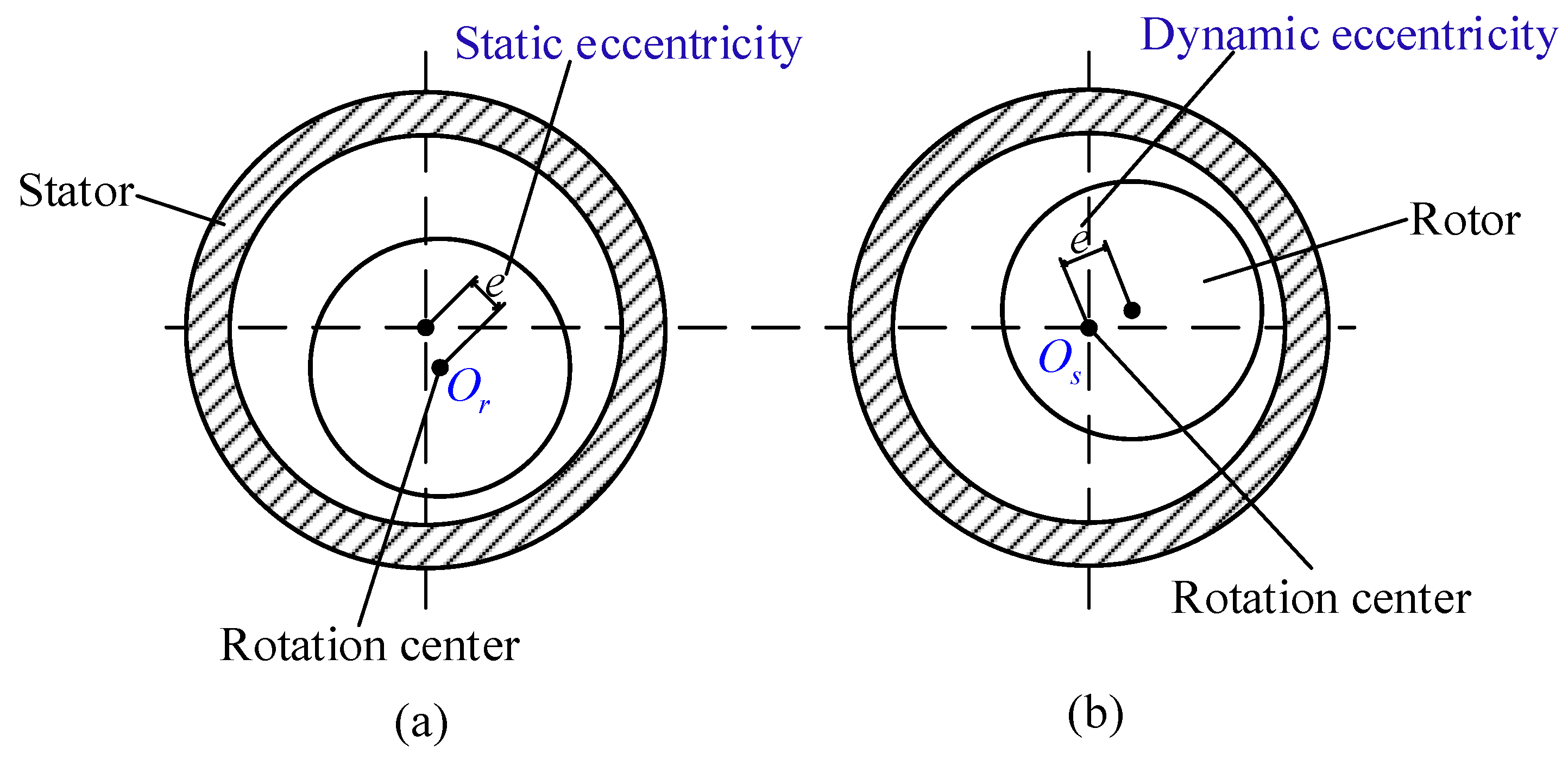
As shown in Figure 2, when the rotor shaft and the stator axis are parallel, the air gap eccentricity can be divided into three categories: one is the static eccentricity which refers to that the air gap eccentricity already exists before operation and the rotor rotates with its own geometric center axis [30,31]. The second category is the dynamic eccentricity which occurs when the stator and rotor are concentric at first and the eccentricity occurs during the operation. The rotor rotates with the geometric axis of the stator [32,33]. Static eccentricity and dynamic eccentricity are the most basic eccentricity types. The third category is the static and dynamic mixed eccentricity, that is, static eccentricity and dynamic eccentricity coexist [33,34,35]. The dynamic eccentricity is mainly caused by the mass unbalance of the rotor. The radial centrifugal force is generated during the rotation of the electrical machine, which results in the uneven air gap between the stator and the rotor. The static eccentricity is easily caused by the installation parallel deviation and bearing wear. Static and dynamic mixed eccentricity can be regarded as the static eccentricity plus the dynamic eccentricity.
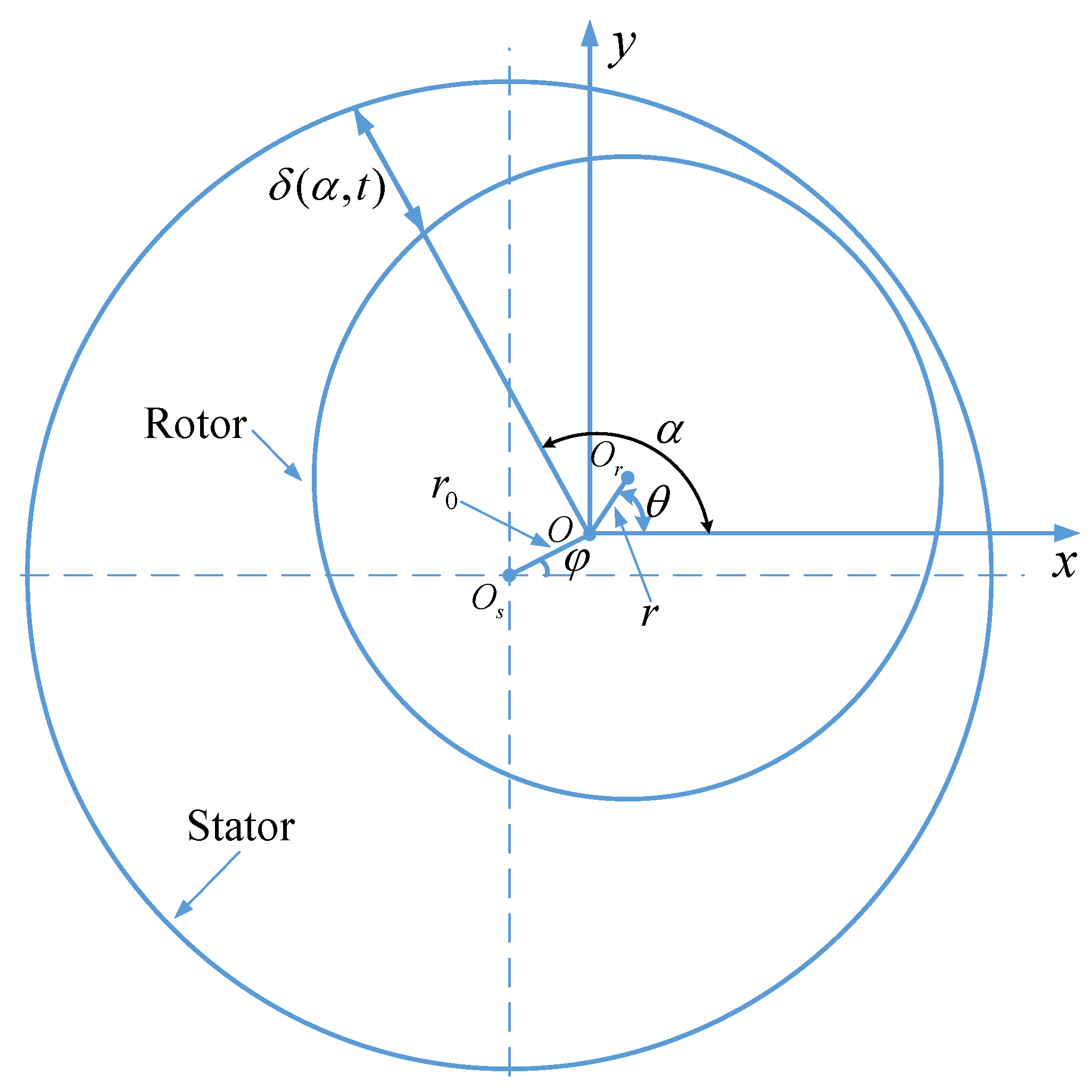
The air gap length for parallel eccentricity is of great importance to the calculation of the UMF and the vibration analysis of the rotor system. Taking the static and dynamic mixed eccentricity (as Figure 3 indicates) as an example, the air gap length formula is derived as follows [36]:
A two-dimensional Cartesian orthogonal coordinate system is established. Os is the geometric center of the stator. O is initial geometric center of the rotor and Or is geometric center of the rotor during operation. By geometric relationship derivation, the air-gap length for static and dynamic mixed eccentricity can be approximately expressed as:
where δ0 is the average air-gap length when the rotor is centered. r0 is the static eccentricity and r is the dynamic eccentricity. α is the air-gap angle with respect to x-axis. φ and θ are the angles of static eccentricity and dynamic eccentricity with reference to x-axis, respectively.
If just the static eccentricity or dynamic eccentricity exists, Equation (1) can be respectively simplified as:
2.1.2. Inclined Eccentricity
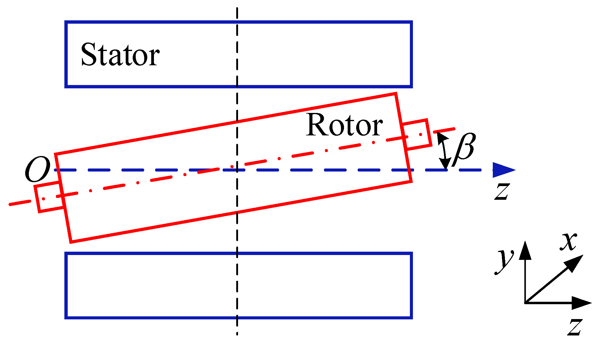
In engineering practice, the height difference between the bearings on both sides of the rotor shaft and the inclination of the shaft etc. will cause air gap differences in the rotor at different positions along the axial direction. This eccentricity is named inclined eccentricity. In 1992 Akiyama [37] proposed inclined eccentricity based on the actual engineering needs. The inclined eccentricity can be further subdivided into symmetrical inclined eccentricity and mixed inclined eccentricity. Symmetric inclined eccentricity means that there is only angular deviation between the stator axis and the rotor shaft. For the mixed inclined eccentricity, there exist angular deviation and radial displacement between the stator axis and the rotor shaft. The mixed inclined eccentricity can be considered as a combination of symmetric inclined eccentricity and parallel eccentricity. Figure 4 shows the schematic diagram of symmetrical inclined eccentricity. Due to the fact that the air gap length of inclined eccentricity is related to the inclined angle and axial position, it is necessary to investigate this problem in the three-dimensional coordinate system.
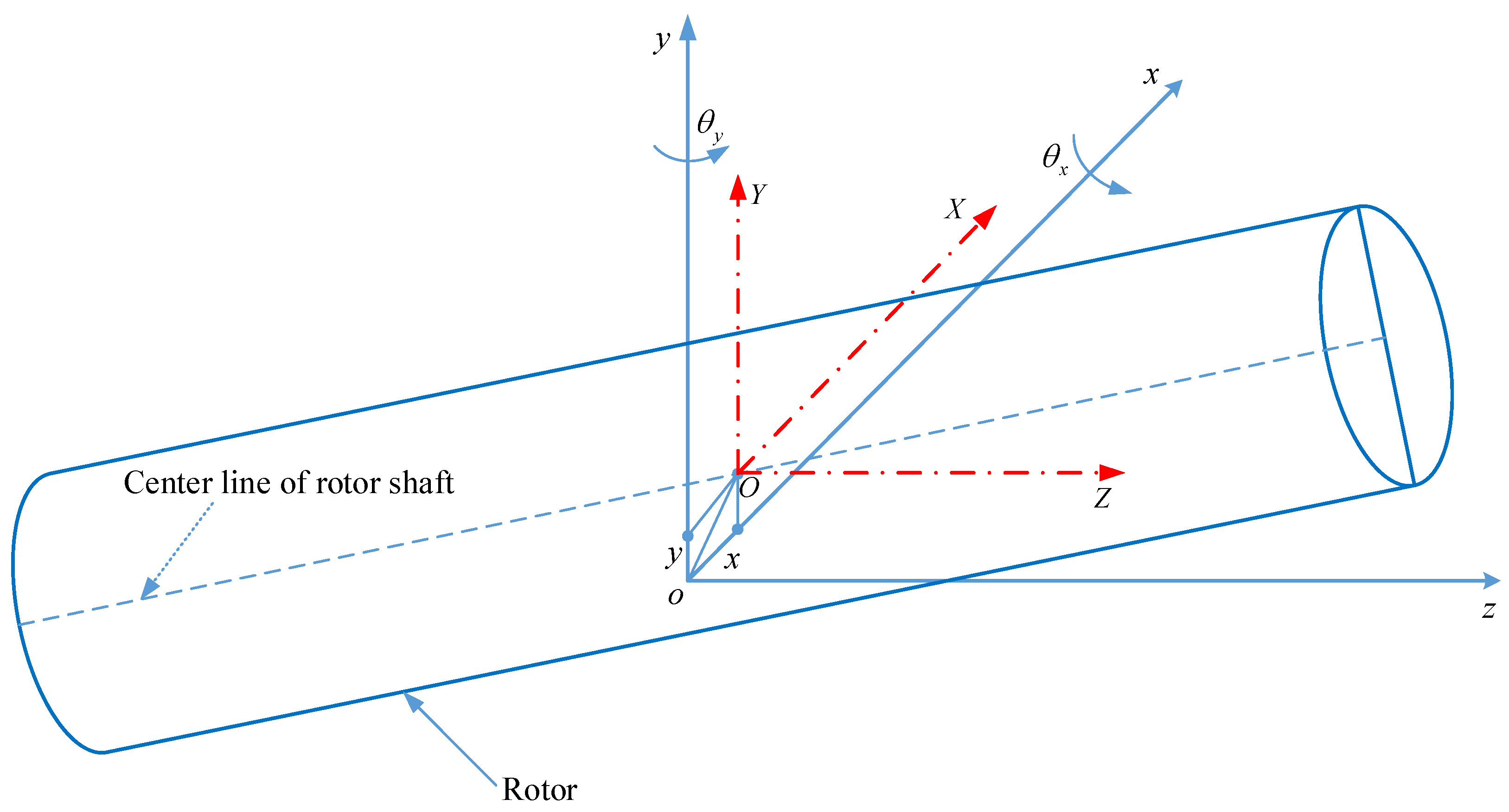
The air gap length of mixed inclined eccentricity is further investigated in the following paragraphs. The general case of air gap changes along the axial direction can be considered as mixed inclined eccentricity [38,39]. As Figure 5 demonstrates, it is assumed that the stator is stationary and the midpoint of rotor in the axial direction is selected to be the origin of the coordinates. There exist two orthogonal coordinate systems in the three-dimensional space and they are parallel. One is the stationary coordinate system O-XYZ for the stator. The other is the unfixed coordinate system o-xyz for the rotor [40].
The parameters that describe the rotor state can be divided into two categories: one is the dynamic parameters (x, y and θx, θy) describing the dynamic displacement and angle responses respectively, and the other is static parameters (x0, y0 and θx0, θy0) representing the static displacement and angle eccentricities respectively. The dynamic parameters are determined by the dynamic responses of the rotor system. However, the static parameters need to be provided in the beginning.
The complex three-dimensional problem can be decomposed to be a two-dimensional eccentricity by cutting the axis into numerous cross sections along the axial direction. The comprehensive eccentricity of the investigated cross section is:
where the value of the coordinate Z is the intersection point between the investigated cross section and OZ axis.
The common range of φ is [0, 2π], while the scope of inverse trigonometric functions is [0, π]. Hence, the following extension is conducted:
The air-gap length is a function of the air-gap angle, time and axial position [41,42,43]. The unified air-gap length in an arbitrary cross-section can be approximately expressed by the equation as follows:
The effective air-gap length along the axial direction becomes short because the rotor is inclined with respect to the stator. The actual air-gap interaction length between the rotor and the stator is determined by the static angle eccentricities and the dynamic angle responses:
where L is the axial length of the air-gap.
2.1.3. Curved Eccentricity
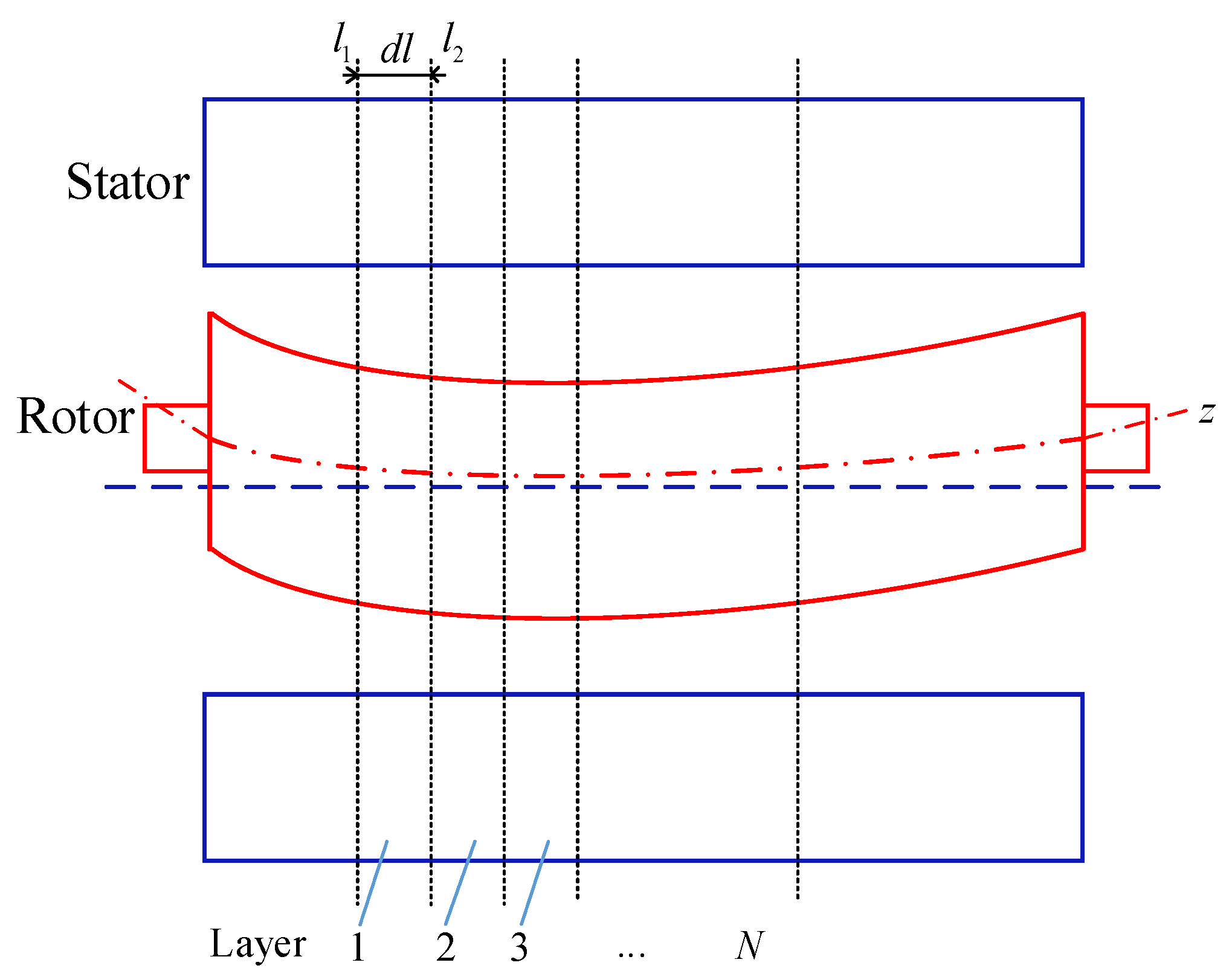
The curved eccentricity always occurs to some extent in most large motors where the axis is bending. For example, a three-phase diving induction motor holds dynamic arc eccentricity. Due to the effects of load or the insufficient shaft stiffness, the shaft will also bend and form curved air gap eccentricity [44,45,46]. The usual way to analyze this complex situation is to treat the electrical rotor as a number of small slices. In each slice, the air gap length can be analyzed according to the pattern of the basic eccentricities (parallel eccentricity or inclined eccentricity).
As shown in Figure 6, in order to obtain the air gap length at different positions, a multi-layer model is designed. The rotor is divided into many layers along the axial direction. Each layer is small enough so that the parallel eccentricity or inclined eccentricity can be applied [47].
To sum up, the common types of air gap eccentricity and logical relationship between them can be summarized in Figure 7:
2.2. Electromagnetic Sources
The sources in electromagnetic aspects can be summarized in four categories: short circuit, open circuit, magnetization unevenness and winding topology asymmetry. Under normal circumstances, the air gap flux and the electromagnetic force distribution are even and symmetrical. When a short circuit occurs in the rotor or stator slot, the magnetic flux of air gap changes. The UMF results in radial vibration [48,49]. The reasons for short circuits include the unfixed excitation winding end, winding deformation, winding manufacturing defects and foreign matter intake, etc. The current flowing through the short-circuited coil is zero, which causes a decrease in the magnetic potential of the corresponding magnetic pole and an asymmetry of the magnetic field. Thereby the UMF is generated. The common types of short circuit are turn-to-turn, coil-to coil, phase-to-phase and phase-to ground short-circuit [23]. Wan et al. [50] studied the influence of the short circuit on the force acting on the rotor and pointed out that the inter-turn short circuit in generator rotor caused thermal imbalance and magnetic imbalance. Wallin et al. [51] studied the UMF and flux density distribution resulting from winding inter turn-short circuits. Through experimental and numerical simulations, it was found that an additional unbalanced electromagnetism was generated.
The open circuit can also make the magnetic circuit unequal [52,53]. Broken rotor bars and broken end rings are the most common open circuit types in a squirrel-cage rotor [54,55]. If the broken bars are distributed over the poles, the current of the broken bars flows to the adjacent bars. This leads to unbalanced magnetic flux. If the broken bars are adjacent to each other, the current of each broken bar may not flow to its adjacent bar, therefore a more uneven magnetic flux distribution occurs. Therefore both the adjacent broken bars and distributed broken bars can result in UMF [56]. Based on the electromagnetic theory, Jung et al. [57] derived a corrosion model for a rotor-bar-fault induction motors. In addition, Baccarini et al. [58] proposed an analytical model for induction machines considered the broken rotor bars and other factors.
Moreover, when the magnetization of the motor material is not uniform, the electromagnetic force per unit area at the rotor surface is different. Therefore the electromagnetic force is not zero [59]. The factors that cause uneven magnetization can be divided into non-uniform magnetization of permanent magnet materials and magnetization of soft magnetic materials. The uniformity of the magnetization is affected by many factors, such as the aging of the magnet, the mutual repulsion of the magnetic field, the asymmetric magnetization during manufacture and the magnetic edge effect of the magnetic ring etc. The magnetization inhomogeneity will make the magnetic circuit asymmetric and produce the electromagnetic force. In addition, the asymmetry winding of the electrical machine will also cause electromagnetic force [60,61,62,63]. Zhu et al. [64] analyzed the electromagnetic force characteristics for permanent magnet motor in the case of completely asymmetrical winding.
3. Calculation Method of the Electromagnetic Force
The calculation of UMF is an important part of any electromagnetic vibration analysis. For the sake of dynamic modeling, the UMF is usually decomposed into a radial force directed to the shortest air gap and a tangential force directed perpendicular to the radial one. Based on the assumption that the magnitude of the electromagnetic force is proportional to eccentricities, Tenhunen et al. [65,66,67] studied the radial and tangential electromagnetic forces of the eccentric rotor at different rotational speeds. Frosini et al. [68] investigated the effects of eccentricity on the radial and tangential electromagnetic forces at open circuit and load. The authors established an analytical function of the electromagnetic force with respect to the known parameters. Wu et al. [61] studied the radial and tangential electromagnetic forces of surface-mounted permanent magnet motors under load and revealed the mechanism of increasing and decreasing the radial and tangential forces. Since the radial component of the air gap flux is much larger than the tangential component, the tangential component is generally neglected in the calculation [69,70,71,72,73,74].
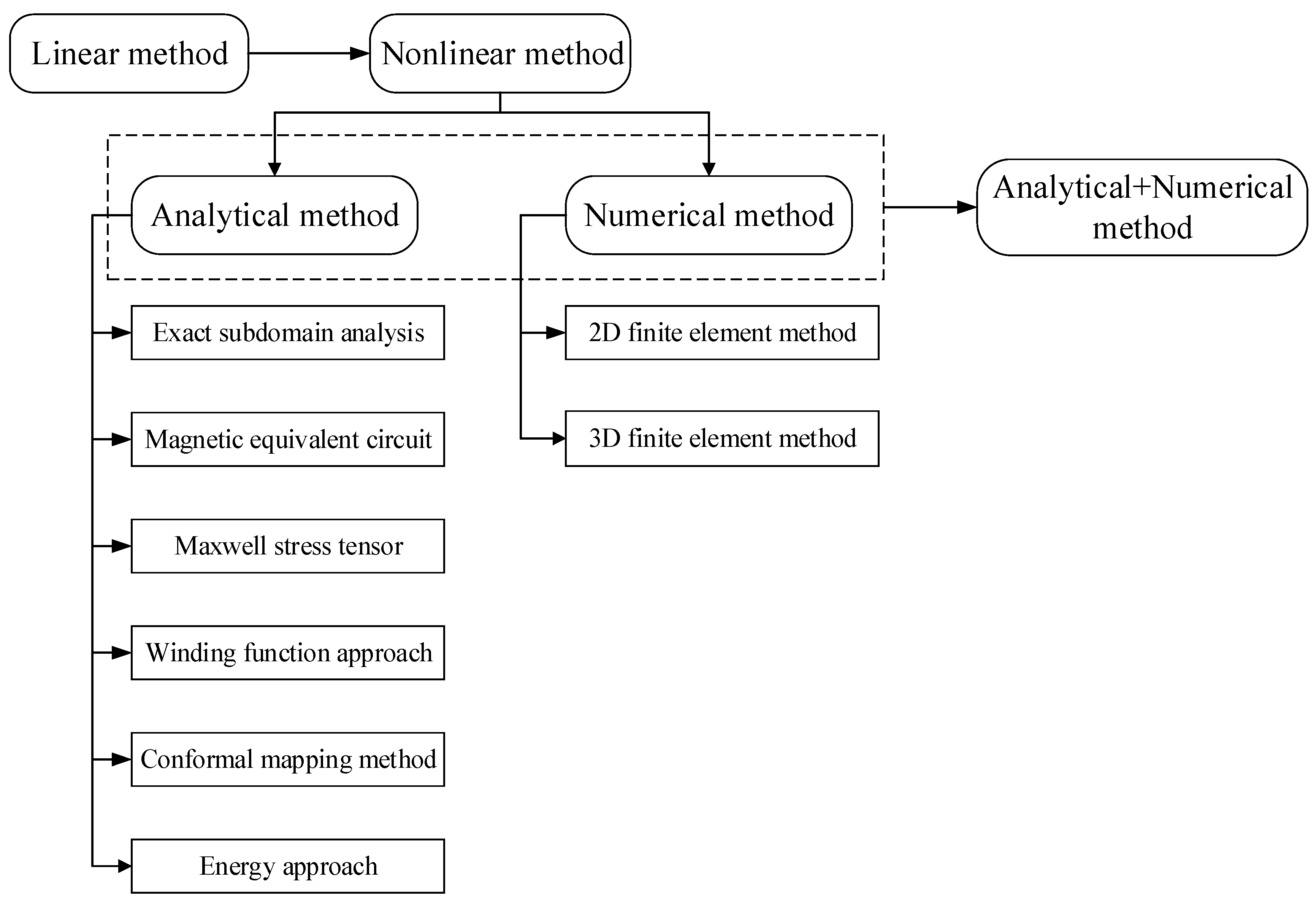
As Figure 8 displays, the calculation method of UMF has undergone a complex development process. The early research mainly focused on the theoretical analysis of electromagnetic force and the linear expression was adopted [75,76,77]. Behrend [75] obtained a linear formula of the electromagnetic force based on the hypothesis that the UMF is proportional to the air gap eccentricity. Calleecharan et al. [76] simplified the electromagnetic force as a linear spring which holds a negative stiffness coefficient when studying industrial hydro-generators. Although linear expressions are simple and convenient, the results are only reliable when the air gap eccentricity is small enough. In 1965, Funke et al. [11] suggested that there was a nonlinear function between the electromagnetic force and the air gap eccentricity. The nonlinear calculation methods of the UMF were widely studied since then.
In recent years, with the increasing reliability requirements for motor product, the nonlinear calculation of electromagnetic force has attracted extensive attention. Many calculation methods are emerging and generally there are three major categories: analytic methods, numerical methods and combinations of analytical and numerical methods.
3.1. Analytical Method
3.1.1. Exact Subdomain Analysis
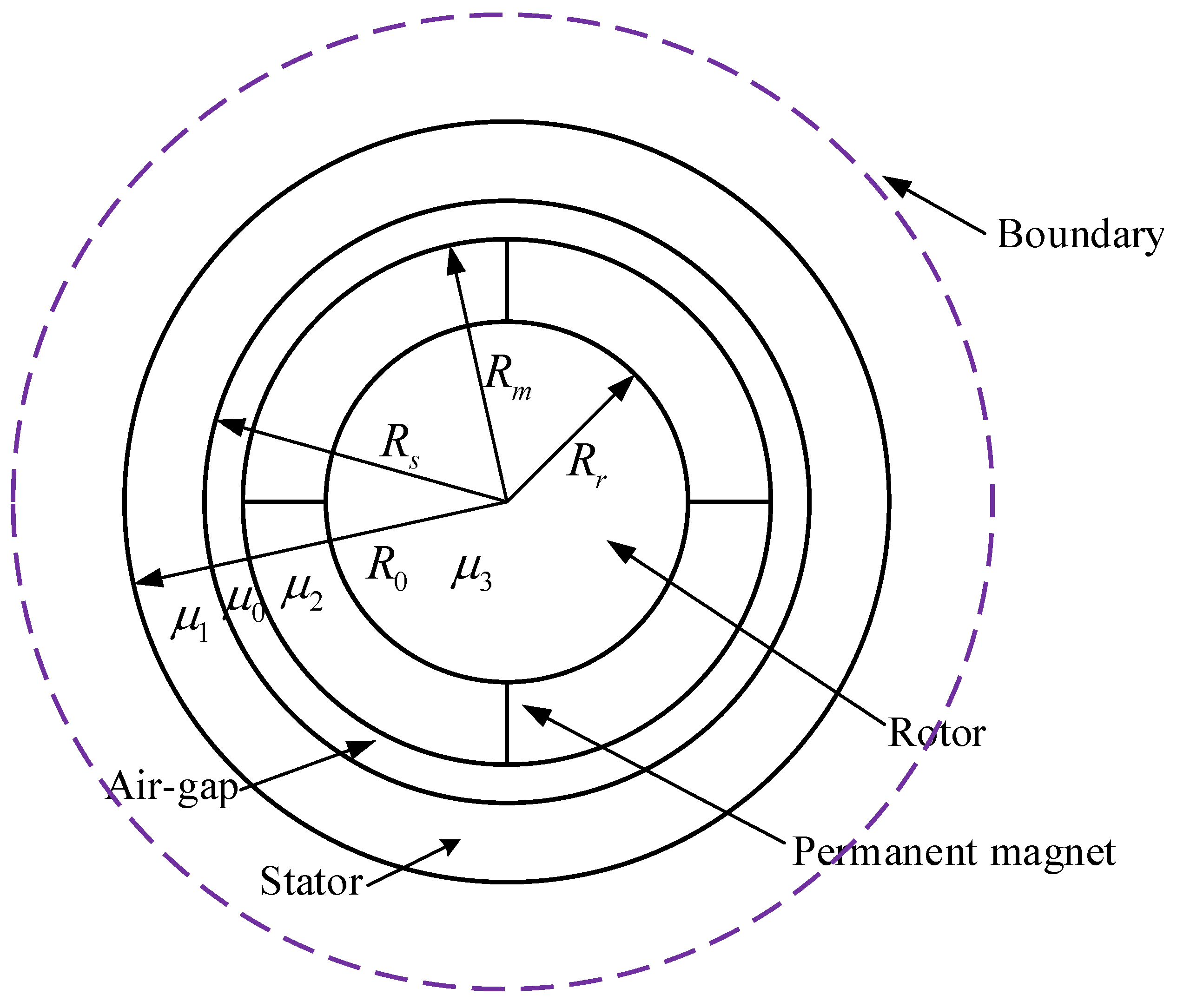
Exact subdomain analysis (ESA) is a method that divides the whole domain of the electrical machine into several subdomains and each subdomain is solved precisely. As Figure 9 displays, the solution domain in the ESA method is divided into five parts: air gap domain, stator core domain, rotor core domain, outer boundary domain and permanent magnet domain. There are boundary conditions between the regions and the radial and tangential components of the electromagnetic force can be considered. To obtain the solution of the air-gap field distribution, some basic assumptions for ESA are needed. For instance, the permeability of stator/rotor iron is infinite and the saturation as well as end effect are neglected.
The scalar magnetic potential distribution in the air gap, stator iron, rotor iron and the exterior region is governed by the Laplace equation. While the scalar magnetic potential distribution in the magnet domain is governed by the quasi-Poissonian equation. These equations are expressed as follows:
where r and θ are the radius and angle of the investigated subdomain in the polar coordinates, respectively. φA, φM, φS, φR and φO represent the magnetic scalar potential in the air gap, magnet, stator, rotor and the exterior region, respectively.
Equations (8)–(12) are usually solved by variable separation technique and many scholars have applied the SEA method to investigate the magnetic field distribution in the electrical machine. The ESA method works for radial or parallel magnetized magnets as well as for the overlapping or nonoverlapping stator windings [78]. In addition, the slotting effects [79,80] and different slot and pole combinations [81] can be considered in the SEA model. In a specific research, the five subdomains are often simplified. For instance, two domains including the air gap domain and permanent magnet domain were investigated [82]. Three domains consist of magnet, air gap and slots were developed [83,84]. Moreover, the ESA method is applicable to many types of electrical machines such as brushless permanent magnet machines and surface mounted permanent-magnet machines etc. Rahideh et al. [14] established a polar coordinate system to analyze the air gap/winding field and permanent magnet field distribution of slotless brushless permanent magnet motor with open circuit. Kumar et al. [85] proposed an improved analytical model by developing the instantaneous air-gap field distribution for a permanent magnet brushless DC motor.
3.1.2. Magnetic Equivalent Circuit
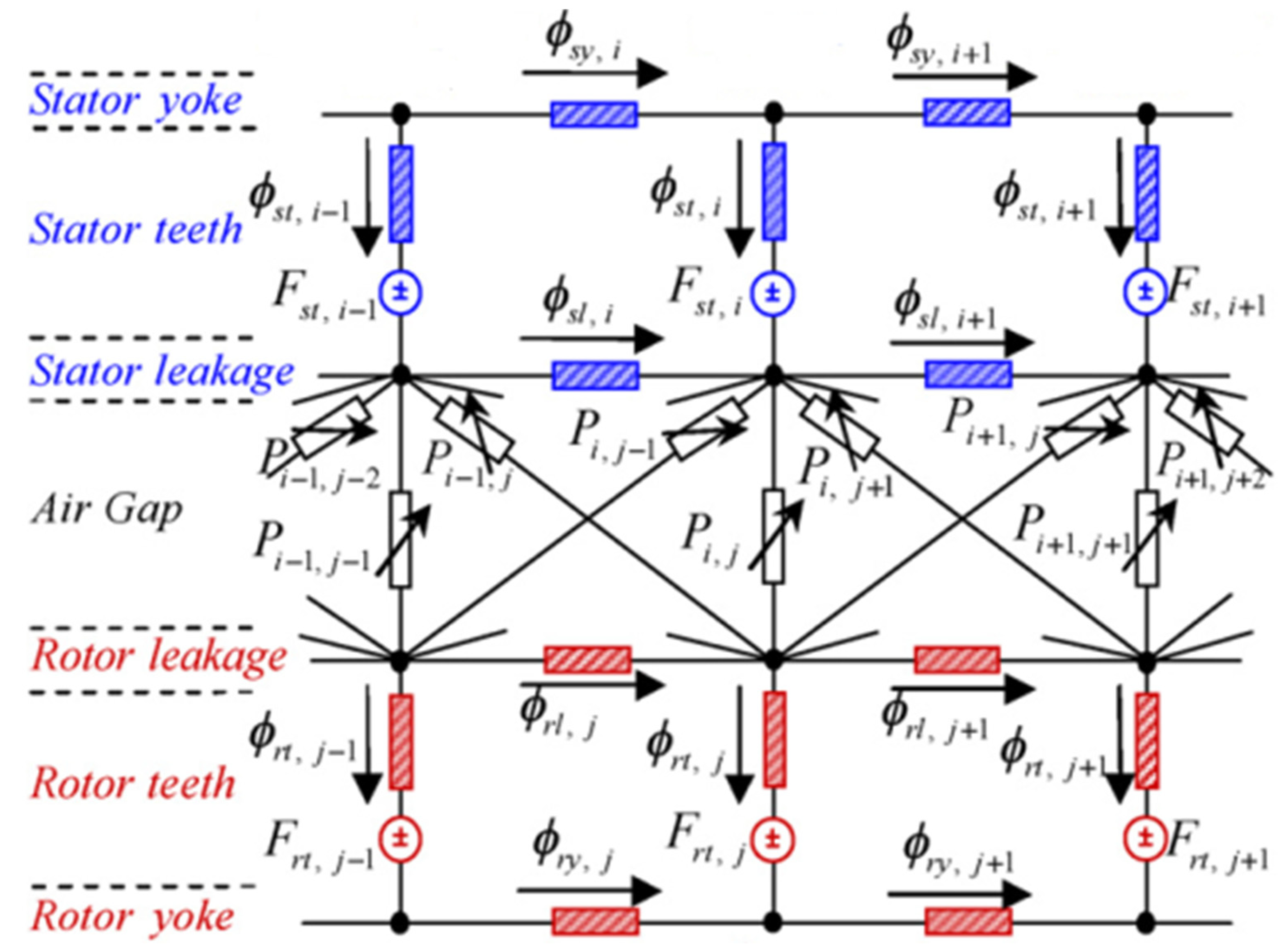
As Figure 10 illustrates, in the magnetic equivalent circuit (MEC) method, the rotor yoke, rotor teeth, rotor leakage, air gap, stator leakage, stator teeth and stator yoke are equivalent to a voltage loop and are superimposed along the magnetic circuit. The nodes of these voltage loop represent scalar magnetic potentials at different positions in the electrical machines. The current in the voltage loop passes through each node and it means magnetic flux goes through the magnetic unit. Figure 10 is an illustration of a permanent-magnet synchronous machine. The physical connection between the left and right ends of the magnetic circuit is modeled through common variables. A linear leakage permeance exists between every two stator teeth due to stator slot opening. The magnetic equivalent circuit method is mainly based on Kirchhoff’s law and Gauss’s law. The equations are solved by the Gaussian elimination method. The MEC can be regarded as a compromise between the electrical lumped-parameter models and finite element analysis. This approach shows the advantage of a close relationship with the physical field distributions in electrical machines. Moderate complexity and reasonable accuracy are reflected in the calculation. When compared with the finite element method, the disadvantages may be that the eddy current and skin effect cannot be handled perfectly.
The MEC method was formally introduced to electromechanical systems by Laithwaite [86] and Carpenter [87], respectively. In the late 1980s, Ostovic developed a series of publications about MEC modeling of induction and permanent-magnet synchronous machines [88,89,90,91]. Since then, the application of MEC method was extensively investigated. The publications are mainly about electrical machines and selected examples are as follow: Sudhoff et al. [92] used the MEC method for induction motor modeling and proposed a methodology of constructing a state-variable model. Serri et al. [93] applied the MEC method to analyze the torque and radial force of a multi-phase bearingless permanent magnet motor, which simplified the design process of the motor. Xie et al. [94] studied the air-gap flux density of a dual-rotor permanent magnet motor by the MEC method and discussed the effects of winding current harmonics, winding types and radial and parallel magnetization types. Based on Kirchhoff’s second law of magnetic circuit, Hanic et al. [95] proposed an analysis approach for saturated surface-mounted permanent magnet motor with no-load by using the conformal mapping and MEC method. Fleming et al. [96] conducted real-time simulation of switched reluctance motor by MEC.
3.1.3. Maxwell Stress Tensor
The Maxwell stress tensor (MST) method describes the interaction between current and magnetic field as well as the distribution of magnetic flux density over the contour of the body. The basic laws of macroscopic electromagnetic phenomena can be expressed by the Maxwell equations. The total force on an object can be obtained by integrating the Maxwell stress tensor over a closed surface enclosing the object [98]. Therefore, when the air gap in electrical machine is considered, the integration surface can be the circular plane between the two bodies and has a cylindrical shape with the normal vector pointing outwards. The Maxwell stress tensor is utilized to calculate electromagnetic force on a moving body:
where volume V contains the investigated object. The Maxwell stress tensor is independent of coordinate system and defined as:
where B is the magnetic flux density. i, j represent the components in the specific coordinate system and δij is the Kronecker delta function. By considering the Gauss’s theorem, the Maxwell stress tensor force can be rewritten in a more convenient form:
where S is a surface enclosing the investigated body and n is a unit vector normal to the surface. For the specific application of MST method in electrical machines, the basic idea is to obtain the Maxwell stress on the rotor surface and the detailed process is presented in the following.
The air-gap permeance can be calculated as:
where μ0 is the vacuum permeability
The magnetic flux density distribution of the air-gap is [99,100]:
where F(α,t) is the synthesis fundamental magnetomotive force (MMF).
The normal component and tangential component of Maxwell stress are:
In general, the tangential component of the flux density is much smaller than the normal component and can be considered negligible. Then the Maxwell stress perpendicular to the core/air boundary is given by:
The two common approaches calculating the Maxwell stress are the Fourier series method [101] and direct integral method [36]. In the Fourier series method, the air-gap permeance can be expanded as a Fourier series:
where ε is the relative eccentricity.
It can be figured out that the first three harmonic components are dominant for ordinary eccentricities. Therefore, by ignoring the higher permeance harmonics and making some simplifications, the resulting electromagnetic forces in the horizontal and vertical direction are obtained as follows:
where p is the number of pole-pair and ω is the supply frequency of the electrical machine. It can be observed that the results change with polyphase excitations:
R and L are the radius and length of the rotor, respectively.
For the direct integration method, the UMF can be obtained by integration of the Maxwell stress on the rotor surface. The expressions for parallel eccentricity are:
If the inclined eccentricity is taken into consideration, not only the electromagnetic force but also the electromagnetic torque need to be calculated:
where l is the axial length of the air-gap and l satisfies the following equation:
The last five years have witnessed some progress in the MST method. Meessen et al. [102] selected the MST method to calculate the magnetic force components in the cylindrical coordinate system. By inserting the analytical expressions, the method can be fast and accurate. Spargo et al. [103] developed a semi-numerical method to calculate the harmonic torque components based on the MST theory which provides a simple algebraic expression. Bermúdez et al. [104] extended the MST method to consider the nonlinear magnetic media and local force distribution. The resultant electromagnetic force was verified well.
3.1.4. Winding Function Approach
The winding function approach (WFA) takes all harmonics of the magnetomotive force into consideration, with no restrictions concerning the symmetry of stator windings and rotor bars. However, the classic WFA is not suitable for the modeling of eccentricities since it cannot consider air-gap variations, although it was initially also applicable of these cases. The mutual inductances between stator phase and rotor loops (Lsr) are different from those between the rotor loops and stator phase (Lrs), and it is difficult to find a physical meaning of this asymmetry. As a result, the modified winding function approach (MWFA) for the inductance calculation considering air-gap eccentricity was proposed [105]. In this method, the air-gap constant is replaced by an air-gap function which depends on the relative position of the rotor with respect to the stator. This method has been applied to analyze static, dynamic and mixed eccentricity in induction machines [106,107]. In addition, this modification can be further extended to consider axial skewing.
The basic idea of WFA can be explained in an induction machine. Taking an induction machine which has m stator circuits and n rotor bars as an example, the cage can be regarded as n identical and equally spaced rotor loops. Voltage equations for the induction machine can be written in vector-matrix form as follows [108,109]:
where:
The stator and rotor flux linkages are given by:
Lss is an m × m matrix with the stator self and mutual inductances, Lrr is an n × n matrix with the rotor self and mutual inductances, Lsr is an m × n matrix composed by the mutual inductance between the stator phases and the rotor loops. Lrs is an n × m matrix and Lrs = LsrT.
The mechanical equations for electrical machines are obtained:
where θr is the rotor position, ω is the angular speed and Jrl is the rotor-load inertia. Te is the electromagnetic torque and Tl is the load torque.
The magnetic co-energy which stores in the magnetic circuits and can be written as:
The electromagnetic torque Te can be obtained from the magnetic co-energy:
According to the WFA, the general expression of the mutual inductance between any winding i and j in any electrical machine is given by:
where g−1(φ, θ) is the inverse air-gap length. Ni(φ, θ) and Nj(φ, θ) are the winding functions of the windings i and j. φ is the angle along the inner surface of the stator and θ is the angular position of the rotor with respect to the stator. The winding function Ni(φ, θ) is a function of φ and θ for a rotating coil. While it is only a function of φ for a stationary coil. This expression is inappropriate to handle arbitrary distribution windings of synchronous machines and the MWFA should be employed.
Much work has been done on the WFA method. Faiz et al. extended the winding function theory for non-uniform air gap eccentricity in rotating electric machinery [110] and applied the MWFA to calculate the time-dependent inductances of the motor with static, dynamic and mixed eccentricities in a unified manner [111]. Ghoggal et al. proposed a MWFA by taking account the skewing rotor bars effects [112] and teeth saturation due to local air-gap flux concentration [113]. Tu et al. [114] investigated the actual winding arrangement of a synchronous machine based on the WFA and Iribarnegaray et al. [115] gave a critical review of the modified winding function theory.
3.1.5. Conformal Mapping Method
The Laplace equations of the magnetic field distribution in the electrical machine are hard to solve directly. A possible solution is to convert this problem into an orthogonal coordinate system by the conformal mapping method (CMM). The CMM can maintain the solution of Laplace’s equation in both the original and transformed domain. If the field distribution (e.g., rectangle, circle) of a geometrical subdomain is known, the field distribution in more complex geometrical subdomains (e.g., slotted air gap) can be calculated by the CMM. The permeance of the electrical machine was often obtained by applying the unit magnetic potential in the CMM. The magnet is ignored and infinitely deep rectilinear stator slots are assumed. The results can be acceptable when the ratio of the air gap length to slot pitch is relatively high. Such a single slot model is appropriate for the electrical machine with a relatively small number of slots. However an electrical machine with plenty of slots are common in ordinary cases. Considering that the effect of slotting on the variation of air gap is similar in an electrical machine, the single-slot approach is extensively investigated [116].
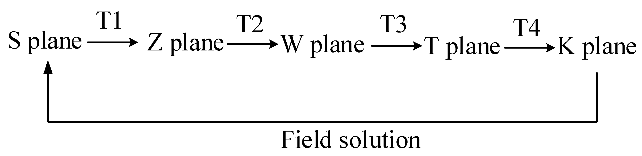
As illustrated in Figure 11, the conformal transformation is applied to transform the geometric shape into a slotless air gap in which the field distribution can be solved. The solution is then mapped back into the complex plane where the actual slot shape exists. Four conformal transformations are required to transform the slotted air gap into a slotless air gap:
The original geometry represents a single slot opening in the S plane. This geometric shape needs to be transformed into its linear model in the Z plane utilizing a logarithmic conformal transformation defined as [117,118]:
where , . The relationship between the coordinate in the S and Z planes is:
The next step is to convert the geometric structure in the Z plane into the upper half of the W plane through Schwarz-Christoffel transformation. The approaches of W plane to T plane and T plane to K plane are similar to that from Z plane to W plane. The individual transformations between the planes can be written as follows:
where . Rs and Rr are the radius of the stator and rotor, respectively. a and b are the coefficients of w at the corner points of the slot.
Finally, the relationship between flux density in the S and K planes is given by:
where is the conjugate of the air-gap permeance with λa and λb as its real and imaginary parts. The flux density Bk with its real and imaginary parts Br and Bθ represents the field solution in the slotless air gap.
There also exist extensive publications about CMM. Lin et al. introduced an analytical method for universal motors based on the actual air-gap field distribution from the field solutions by the CMM [119], and presented a generalized analytical field solution for spoke type permanent magnet machines [120]. Hanic et al. [95] proposed a novel method for magnetic field analysis based on the CMM and MEC. Alam et al. [121,122] took the slotting effect, winding distribution, armature reaction and saturation effect into account. They presented an improved CMM for magnetic field analysis in surface-mounted permanent magnet motors considering eccentricities.
3.1.6. Virtual Work Principle
The force in the virtual work principle (VMP) is calculated from a spatial derivative of stored energy. The VMP obtains the air gap magnetic field through the electromagnetic theory and the corresponding boundary conditions. Moreover the energy function of the air gap magnetic field is obtained. The partial differentials of energy function in horizontal direction and vertical direction are obtained respectively. By using the method of electromechanical analysis, the coupling dynamics equation is established. These strong nonlinear equations are solved by mathematical transformation.
The magnetic field energy of the air gap space is calculated first and the magnetic tube energy of air gap is:
The magnetic field energy of the air gap space is:
The electromagnetic force in the x-direction and y-direction can be obtained by the derivation of energy:
The VMP has developed for a long time and the existing publications about this method mainly emerged in the late 1990s. Several authors have calculated spatial derivatives of position-dependent air gap reluctances and formulated an analytical expression for force and torque in terms of these derivatives [123,124]. Others have implemented VWP discretely by evaluating the total system energy difference and dividing through the spatial difference [125,126].
3.2. Numerical Method
3.2.1. 2D Finite Element Method
The numerical calculation of electromagnetic field is a problem about solution of partial differential equations. For many practical engineering problems, the application of finite element methods (FEM) based on variational principles is often easier than the direct solution of partial differential equations. The Maxwell stress method and virtual work method are usually used for calculating the UMF in the FEM. The FEM divides the continuous field into finite units and then expresses the solution of each unit by the interpolation function which makes it meet the boundary conditions. Then the solution of the continuous field over the entire field is obtained. Numerous scholars studied the FEM for the magnetic field distribution of electrical machines and the FEM is often applied as the contrast or verification for the analytical methods. The FEM can be generally divided into 2D FEM and 3D FEM from the perspective of investigation scope. Moreover, it can be also classified as static FEM and dynamic FEM which is also named time-stepping FEM.
The 2D FEM was adopted to investigate the electromagnetic characteristics of the switched-flux permanent magnet motor [127] and the squirrel-cage induction motor [128]. In addition, the time steeping FEM was developed to solve the transient magnetic field in induction machines [129,130]. Wang et al. [131] overcame difficulties of hundred stator slots operating under loads and proposed a method for the 2D finite element calculation of UMF in large hydro-generators. Zarko et al. [132] used the FEM to calculate the UMF of a salient-pole synchronous generator in no-load and loaded conditions. Lee et al. [133] adopted the 2D FEM to model magnetic vibration sources in two 100-kW marine fractional-slot interior permanent magnet machines with different pole and slot combinations.
3.2.2. 3D Finite Element Method
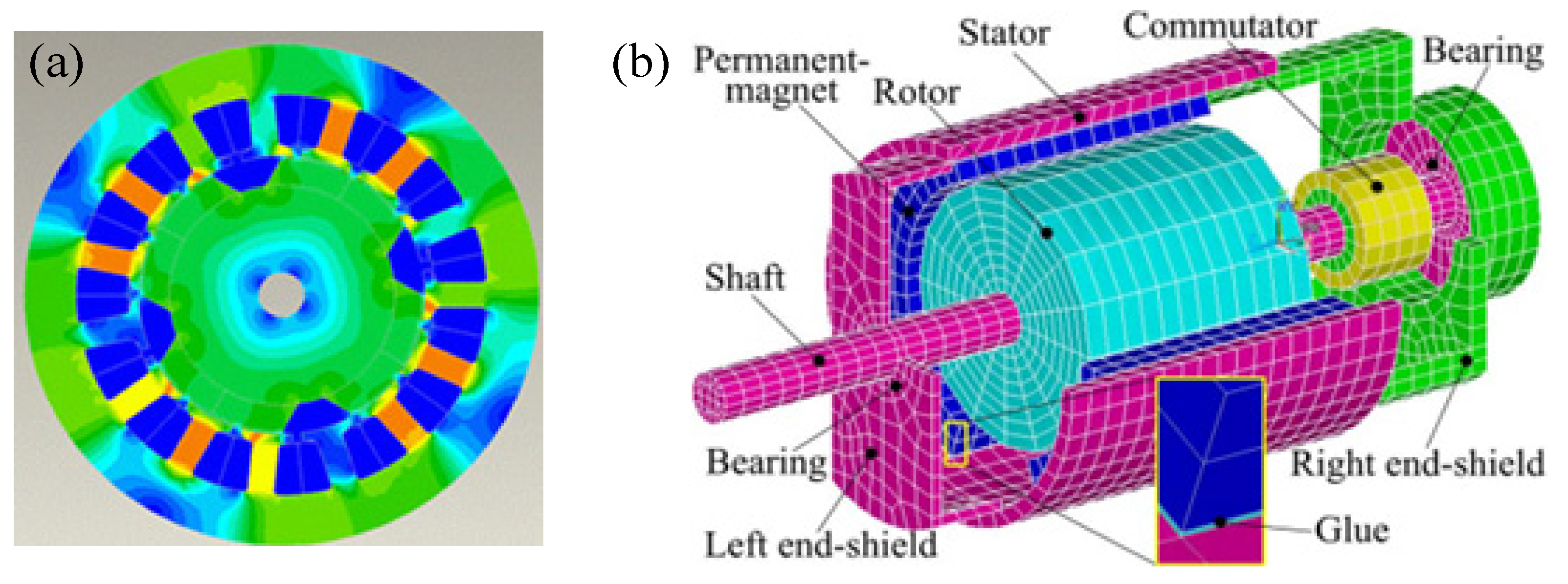
As illustrated in Figure 12, 2D FEM simplifies the electrical machine system to be a plane problem, while the 3D FEM investigates the issue in the space. Therefore the results obtaining by 3D FEM are more accurate to some extent due to the fact that less assumptions are made. Lee et al. [134] applied the 3D EFM to study the performance of traditional longitudinal flux and transverse flux permanent magnet motors. Chen et al. [135] developed a finite element solution approach for the analysis of the dynamic behavior and balancing effects of an induction motor system. Sibue et al. [136] studied the current density distribution and losses in a large air-gap transformer composed of toe cores and two windings using homogenization and 3D FEM. Ha et al. [137] investigated the coupled mechanical and magnetic forces by the FEM in the transient state solved in a step by step procedure with respect to time. Faiz et al. [129] proposed a time-stepping FEM that identifies mixed eccentricity and overcomes the difficulty of applying FEM to transient behaviors.
The current density is considered as input of 2D FEM which neglects the harmonics of the stator current. The current and rotor angular position can be appropriately considered in the 3D FEM. Generally speaking, the 3D FEM is more time consuming but accurate compared with the 2D FEM. If the size of electrical machines is large or the requirements of calculation accuracy are harsh, the 3D FEM model is needed.
3.3. Comprehensive Method
The analytical method which can obtain the origin and frequency characteristics of the electromagnetic force is mainly used to explore the mechanism and the solution speed is fast. However the calculation is simplified based on many assumptions and the model is relatively simple. The numerical method can consider more parameters and the accuracy of calculation results is more reliable than the analytical method. However it requires massive time and the computational efficiency for large as well as complex situations is low. Based on these characteristics, some scholars develop a numerical plus analytical calculation method, which takes advantage of the merits of simple analytical method and numerical method. Numerical method is used to solve electromagnetic field distribution for obtaining accurate magnetic flux density. Analytic method is adopted to get the electromagnetic force and the computational efficiency is improved. In addition, experiments are applied to verify the calculation results and this approach is being widely promoted. He et al. [138] combined the FEM with the boundary finite element method to study the electromagnetic, mechanical and acoustic characteristics of permanent magnet DC motors. First, the MMF harmonic of the candidate winding was obtained by analytical method and then each set of harmonics was analyzed by a simplified FEM. Li et al. [139] proposed a semi-analytical method to analyze the eddy current loss of an axial flux permanent magnet motor. Tudorache et al. [140] proposed a hybrid model (numerical and analytical combination) to reduce the cogging torque of a permanent magnet synchronous motor. Compared with the FEM, the computational time was very low and the calculation accuracy remained high.
Based on the advantage combinations of the analytical and numerical methods, Chao [141] proposed a hybrid method to analyze the UMF in hard disk drive spindle motors. Hanic et al. [95] adapted the conformal mapping and magnetic equivalent circuits to calculate the back electromotive force and cogging torque of saturated surface-mounted permanent magnet machines. Sprangers et al. [142] presented a semi-analytical method based on the harmonic modeling technique and analyzed the magneto-static field distribution in the slotted structure of rotating electrical machines. Guo et al. [143] combined the analytical and FEM techniques to predict the air-gap magnetic field distribution of a permanent motor embedded salient pole.
3.4. Main Factors Considered in the Calculation
The values of UMF are influenced by many factors. The existing calculation methods are all based on some assumptions, even though the numerical method (which here refers to FEM) can take numerous situations into account. Considering that proposing an exactly perfect model is rather difficult and may be very complex, some key influential factors are needed to paid more attention. This way is efficient in improving the accuracy and will not increase the complexity much at the same time. According to the literature review, the relatively important factors are magnetic saturation, slot and pole combination and load effects.
3.4.1. Magnetic Saturation
In 1918, Rosenberg [144] discovered the effect of magnetic saturation on UMF, which attracted the attention of many researchers. With the increase of excitation current, UMF increases nonlinearly under normal circumstances, but the existence of magnetic saturation limits the infinite increase of electromagnetic force. In addition, the complex geometry structure of rotor and stator tends to cause magnetic field distortion. The magnetic saturation may also be formed in the narrow places wherein slot and pole are located. Generally speaking, the saturation phenomenon is inevitable because of two major factors. One is due to the saturation effects of magnetization characteristic in the ferromagnetic materials. The other is the existence of magnetic flux leakage caused by the distortion in the narrow air-gap space. There exists much evidence supporting the fact of magnetic saturation [145]. The magnetic saturation will have a great influence on the UMF and extensive studies have been conducted. Variable degree of saturation [146] and nonlinear magnetic saturation [147] were investigated, respectively.
Calculation methods considering the influence of magnetic saturation effect are emerging in the last decade. Covo [76] used the slope of the magnetization curve to analyze the effect of saturation on the UMF, which was verified by Tenhunen [67] experimentally. Ohishi et al. [148] made further improvements on this method by applying the magnetization curve of the ferromagnetic material and obtained the polynomial relationship between the air gap flux density and the excitation current in the non-air gap portion of the motor. A polynomial equation describing the magnetization curve of the electrical machine was obtained based on the air gap line. Perers et al. [149] studied the effect of magnetic saturation in a hydro-generator eccentric rotor on UMF, which indicated that magnetic saturation significantly influenced the UMF at high voltage and high load. Dorrell [38] proposed a flexible UMF calculation method considering the situation of axial eccentricity and magnetic saturation, and this approach can be applied in the design process effectively.
3.4.2. Slot and Pole Effects
The N-S poles are common in the electrical rotor. The stator slots with the current form winding current. Many calculation methods ignore the influence of poles and slots on the magnetic field distribution. However, the pole and slot change the density of the magnetic field lines and affect the calculation accuracy of UMF. According to the relationship between the number of rotor poles and the stator slots, the combination of poles and slots can be divided into two major categories: one is the integer combination, that is, the ratio of stator slot number to rotor pole number is a positive integer and the other is a fractional combination. More and more motors begin to adopt fractional combination and the systematic research is necessary to investigate its influence on the UMF. On the other hand, the slot skewing may also have a great influence over the harmonics of UMF [150,151].
Some studies showed that harmonics of air gap magnetic flux density generated by the slotted rotating machinery were an important part of UMF [152]. The slotting effect will cause an additional magnetic field [153]. Furthermore it was found that the vibration modes and frequency components of higher harmonics strongly depend on the combination of the pole-slot number [154,155] and shape of poles [156]. Zhu et al. [60] analyzed the influence of different pole/slot combinations on the UMF and found that UMF increases for higher fractional pole-to-slot ratio. In another article, Zhu et al. [157] further proposed the additive effects (p = 3k + 1, p-pole number and k-slot number) and cancelling effects (p = 3k − 1) of different pole/slot combinations on UMF. The slotting effects and air gap eccentricity are often investigated together in recent years. Zarko et al. [117] proposed an analytical method for magnetic field distribution in the slotted air gap of a surface-mounted permanent magnet motor. Bao et al. [158] combined the effects of eccentricity and slotting to conduct magnetic field monitoring in a submersible motor.
3.4.3. Load Effects
According to the basic electromagnetic relationship inside the electrical machine, the magnetic field generated by the stator current and the magnetic field generated by the excitation current are superposed to form the composite air-gap magnetic field under the load condition. Many studies calculated the UMF based on the open-circuit current without load [159]. This assumption is applicable and reasonable in ordinary cases because the load has little effect on the calculation of UMF. Wang et al. [2] investigated the effect of different load conditions (no load, half rated and rated load) on the UMF and obtained the conclusion that the load had little effect on the electromagnetic force. Although the load current and power factor have changed with load, the UMF has little change compared with no-load [160]. The no load cases are widely investigated and the discussions are extensive. For example, Gaussens et al. [43] proposed a general and accurate approach to determine the no-load flux of field-excited flux-switching machines. Hu et al. [161] presented an improved analytical subdomain model for predicting the no-load magnetic field and cogging force.
However, the load in electrical machines exists actually and the effects of load cannot always be ignored. When the accuracy demands for calculations are harsh and the load is high, the load factor should be taken into consideration seriously. Moreover, in the case of saturation, the existence of load may weaken the UMF. Therefore it should be investigated respectively. Perers et al. [149] pointed out that the UMF decreased with increasing load at a given terminal voltage because the inter-pole leakage flux became more pronounced with increasing load. Zhu et al. [60] established a general analytical model in a two-dimensional polar coordinate system and studied the UMF during loading. Studies showed that the additional UMF was large when the electrical load was high. Dorrell et al. [162] pointed out that there was only rotor flux component when the motor was open without load. Flux components were contained in both stator and rotor under load conditions.
4. Characteristics of Electromagnetic Vibration and Experimental Study
4.1. The Magnitude and Frequency of the Electromagnetic Force
Electromagnetic force is an electromagnetic attraction that pushes the rotor toward to the stator. As the vibration increases, the air gap length will become smaller and smaller and forms negative feedbacks which further aggravate the vibration. Therefore the UMF is always in the smallest air gap direction. The magnitude of the force is influenced by many factors such as eccentricity, current and winding structure etc. Research have shown that the magnitude of UMF has the nonlinear relationship with these factors and specific situation should be investigated respectively [163]. The UMF is rotating if the electrical machine is on operation. Otherwise the force is static.
The common source of UMF is eccentricity. In addition, the static and dynamic eccentricities tend to coexist. The equation describing the frequency components of interest is [22]:
where R is the number of rotor slots, p is the number of fundamental pole pairs, f1 is the fundamental supply frequency, s is the slip, nd is the eccentricity order (nd = 0 in case of static eccentricity and nd = 1 in case of dynamic eccentricity), n is the any positive integer, nsat models magnetic saturation (nsat = 0, 1, 2, …) and k is the order of the stator time harmonics that are present in power supply driving the motor.
When neglecting saturation and considering only static eccentricity, the frequency components that are characteristic of a failure agree exactly with the rotor slot harmonics. Furthermore, in the case of saturation, new sidebands around dynamic-eccentricity-characteristic components will appear, according to the combinations of the feasible values of nd and nsat. Classic theory predicts that spatial harmonics of (p ± 1) pole pairs will result from pure dynamic eccentricity. The frequencies of these harmonics will be given by (f1 ± fr), where fr is the rotor frequency. Nevertheless, in practical applications, it is likely that these additional fields caused by dynamic eccentricity may induce currents in stator windings because the motor is not completely electrically and magnetically symmetrical. Moreover, the low-frequency components near the fundamental given by:
where fr is the rotating frequency.
The magnitude of UMF due to rotor eccentricity is relatively large because of the existence of the direct-current (DC) component in the static eccentric cases and the low fundamental frequency content in dynamic eccentric cases. The magnitude of the force decreases with the increasing of the frequency harmonic. Therefore the magnitudes of the DC component and low frequency content are large and dominate [164]. The effects of first several frequency harmonic are often investigated in detail among publications. Arkkio et al. [165] pointed out that the static eccentricity generates an additional force component varying at twice of the supply frequency. Pennacchi et al. [166] investigated the rotating component and twice of it in the UMF for a three-phase generator. Li et al. [167] found that the 3rd harmonic magnetic force plays a major role in the production of the squeaking noise in small permanent magnet DC brush motors.
4.2. Measures to Reduce Electromagnetic Vibration
Electromagnetic vibration will cause stability problems and affect the safe and stable operation of the system. Some measures are needed to reduce the vibration of the electromagnetic excitation source. Currently the equalizing winding, damping winding, parallel circuit, magnetic saturation and slot/pole combination are mainly adopted in the electromagnetic vibration suppression. The parallel circuit and damping winding methods are the effective approaches that have been extensively investigated [27].
The parallel circuit is achieved by reconnection of the stator coils groups. Magnetic field harmonics due to rotor eccentricity generate currents circulating in the parallel paths of the rotor and stator windings. These currents equalize the magnetic field distribution in the air gap and hence reduce the resultant UMF. Burakov et al. [100] compared the two approaches (stator parallel paths and rotor windings) reducing UMF in detail. The study found that parallel stator windings can reduce the UMF more effectively than damping windings. Wallin et al. [168] used parallel circuit method to reduce UMF of a synchronous motor. The research shows that the reduction of UMF strongly depends on the relative unbalanced direction of the stator current isolation line.
In the studies of damping winding, Dorrell et al. [169] found that damped windings can significantly reduce the UMF. Wallin et al. [170] studied the effect of damping winding on UMF in an eccentric salient pole synchronous motor. It was found that continuous or discontinuous damping winding produced different damping winding currents, but the influence on UMF was similar. Dorrell [70] analyzed the effect of damped windings in induction machines on reducing the UMF, and thereby reducing bearing wear on the rotor system.
In addition, many other methods are applied to reduce the UMF. For example, Nguyen et al. [171] designed the dual-stator to reduce the UMF for a wound-field flux switching machine. Bi et al. [172] revealed that lead wires can generate severe UMF in permanent magnet synchronous motor, especially at high speed and propose several ways to reduce lead wire asymmetry. Oliveira et al. [173] proposed an equipotential bonding method to change the magnetic attraction force on the circumference of a rotor, and thereby reducing the UMF.
4.3. Experimental Study
The publications on theoretical modeling and analysis about UMF are extensive, but experimental data for the measurement of UMF is sparse due to the difficulties in building suitable experimental equipment. The measurement of the air gap field is rather difficulty. Dorrell et al. [145] reviewed the experimental data available about UMF in induction motors and also put forward further data for consideration.
The experiment method of UMF can be divided into direct approach and indirect approach. Considering that the UMF in a real machine is difficult to be measured, the indirect approach is usually adopted [174]. For instance, Pennacchi et al. [16] evaluated the UMF effects indirectly by means of the vibrational behavior of the machine. Zarko et al. [132] carried out the measurement and analysis of bearing and shaft vibrations with no-load and loaded conditions. Kim et al. [175] developed an experimental device to measure the axial UMF and verify the simulated results in brushless DC motors. The experimental setup is illustrated in Figure 13 as follows:
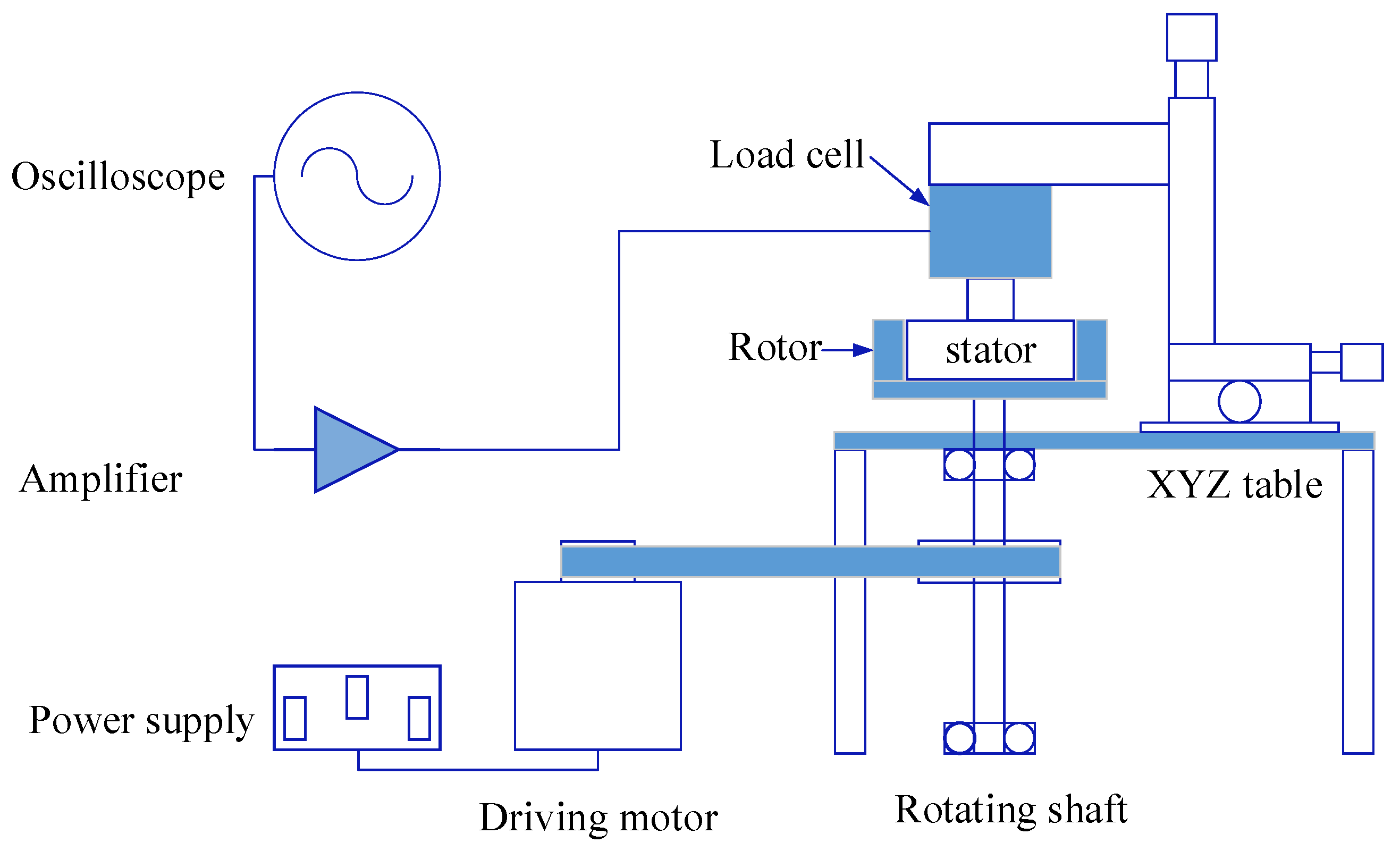
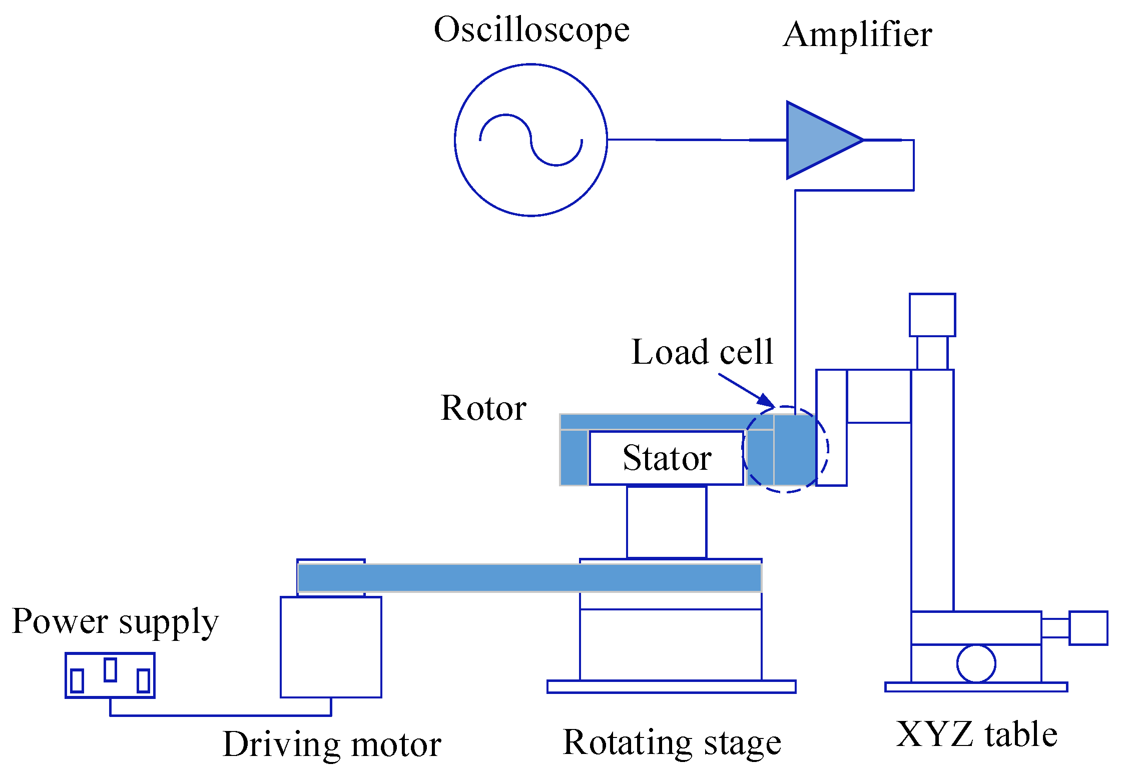
The direct experiment method was studied by Lee et al. [176]. As displayed in Figure 14, the rotor is separated from a stator and the stator eccentricity is adjustable. The disassembled rotor is clamped with a load cell and there are no bearings. This experimental device measures the variation of UMF by the load cell on the stationary rotor. The experimental setup is demonstrated as follows:
The experimental approaches are usually adopted to conduct some verifications for the analytical or numerical calculation methods. Kumar et al. [85] compared the analytical results with the experimental results based on the back electromotive force (EMF) which is obtained from the air-gap field distribution. Kim et al. [128] compared the back EMFs measured in the experiment with simulation results and verified the proposed FEM method. Wang et al. [177] conducted the experiment to validate the theoretical analyses and FE results for the surface mounted permanent-magnet machine.
5. Development Trend and Prospect
5.1. Accurate Calculation of Electromagnetic Excitation
The mechanism of UMF is complicated and further exploration is needed. Moreover the calculation of UMF is still the focus of future research. There is no universally applicable nonlinear analytical expression for computing the UMF so far. Although extensive research about the nonlinear analytical expression of UMF has been conducted, it is based on some assumptions and simplifications. The computational accuracy needs to be improved and the applicability of obtained expressions are limited. The finite element method is more accurate, but tedious steps and time-consuming highlight the limitations in practical applications. Accurate analysis and calculation of UMF under different operating conditions is an important research topic in the design. Therefore, it may be a future research direction to explore the accurate and universal nonlinear model for UMF.
5.2. Control of Electromagnetic Vibration
Electromagnetic vibration threatens the safe operation of the entire system. Measures to reduce or eliminate the UMF for the purpose of reducing vibration and noise have been studied. These measures mainly make the electromagnetic field between the stator and stator be as uniform as possible from the aspects of improving the manufacture and installation precision, carrying out multiple balancing checks and arranging the circuit structure rationally. However, as electrical machines move toward high-speed, heavy loads and subtle trends, efficiency and operability will constrain the use of these measures. If a sudden fault caused by the electromagnetic field changes affects the normal operation of the electrical machines, all possible influencing factors need to be checked. This situation cannot meet the long-time and trouble-free design requirements. The frequency components of UMF can be adopted as the basis for fault diagnosis and the fault characteristics can be extracted for targeted dynamic parameters adjustment. At the same time, the dynamic characteristics of the electrical machine can be applied as the monitoring object for fault diagnosis, and thus forming a feedback system. Real-time monitoring and adjustment of the parameters can ensure safe and stable operation of the electrical machine. Therefore, the adoption of electromagnetic vibration characteristics in the vibration control will be a worthwhile study field in the future.
5.3. Multiphysics Coupled Modeling
At present, the research of electromagnetic vibration mainly investigates the effect of UMF on solid structures, and ignores the further influence of the structural field on the electromagnetic field. The weak interaction between solid field and electromagnetic field was involved. Future studies will gradually focus on the strong interaction between solid and electromagnetic fields. The end of electrical machines will heat up during operation, which causes variations in the magnetic field. In addition, the mechanical strength and stiffness properties of the device will change. All these factors influence the vibration characteristics. Moreover the air flow of ventilation components, air flow interference during high-speed operation and the external sound field excitation may affect the dynamic characteristics of electrical machines. Coupling vibration between rotating machinery and electromagnetic field is worth exploring. Meanwhile, the rotating structure is affected by the temperature field and surrounding acoustic excitation [178]. Due to the flexibility of structure, the multiphysics interaction will produce significant effects on the dynamic properties of structures. Therefore, the coupling of flow field, structure field, temperature field, electromagnetic field, sound fields and other physical field will be a trend in the future modeling of electrical machines. In addition, the multiobjective and multidisciplinary approach for the system-level design optimization of electrical machine systems are necessary. Moreover, material model, manufacturing condition, electromagnetic, thermal and mechanical models should be investigated for the motor-level design optimization in future work [17,18,19,20].
6. Concluding Remarks
Over the past decades, research on the dynamics and vibration of electrical machines has undergone great progress. This paper provides a comprehensive review of the electromagnetic vibration in electrical machines. The basic but important aspects such as sources, calculations, characteristics and experiments of electromagnetic vibration are summarized in detail. The mechanisms for mechanical and electromagnetic factors were revealed, especially the modeling of different air-gap. Different calculations methods which include ESA, MEC, MST, WFA, CMM, VMP, 2D FEM, 3D FEM and comprehensive approaches were demonstrated. Main factors such as magnetic saturation, slot and pole as well as load effects were involved. The magnitude, frequency and reduction measures of the electromagnetic vibration were presented. The common experiment schemes were summarized and the research prospect was provided. This paper can be benefit for the majority of scholars in this field to promote the ongoing progress and development of the investigation.
Author Contributions
Conceptualization, X.X., Q.H. and F.C.; Methodology, X.X.; Software, X.X.; Validation, X.X., Q.H. and F.C.; Formal Analysis, X.X.; Investigation, X.X., Q.H. and F.C.; Resources, F.C.; Data Curation, X.X.; Writing-Original Draft Preparation, X.X., Q.H. and F.C.; Writing-Review & Editing, X.X.; Visualization, X.X.; Supervision, F.C.; Project Administration, F.C.; Funding Acquisition, F.C.
Funding
The authors gratefully acknowledge the financial support from Natural Science Foundation of China (Grant Nos. 51335006 and 11472147).
Conflicts of Interest
The authors declare no conflicts of interest.
Abbreviations
| UMF | Unbalanced magnetic force |
| ESA | Exact subdomain analysis |
| MEC | Magnetic equivalent circuit |
| MST | Maxwell stress tensor |
| MMF | Fundamental magnetomotive force |
| WFA | Winding Function Approach |
| MWFA | Modified winding function approach |
| CMM | Conformal mapping method |
| VWP | Virtual work principle |
| FEM | Finite element method |
| 2D | Two degrees of freedom |
| 3D | There degrees of freedom |
| DC | Direct-current |
| EMF | Back electromotive force |
References
- Rodriguez, P.V.J.; Belahcen, A.; Arkkio, A.; Laiho, A.; AntoninoDaviu, J. Air-gap force distribution and vibration pattern of induction motors under dynamic eccentricity. Electr. Eng. 2008, 90, 209–218. [Google Scholar] [CrossRef]
- Xu, X.P.; Han, Q.K.; Chu, F.L. Nonlinear vibration of a rotating cantilever beam in a surrounding magnetic field. Int. J. Non-Linear Mech. 2017, 95, 59–72. [Google Scholar] [CrossRef]
- Dorrell, D.G.; Thomson, W.T.; Roach, S. Analysis of air-gap flux, current, vibration signals as a function of the combination of static and dynamic air-gap eccentricity in 3-phase induction motors. IEEE Trans. Ind. Appl. 1997, 33, 24–34. [Google Scholar] [CrossRef]
- Smith, A.C.; Dorrell, D.G. Calculation and measurement of unbalanced magnetic pull in cage induction motors with eccentric rotors. Part 1: Analytical model. IEEE Proc. Electr. Power Appl. 1996, 143, 202–210. [Google Scholar] [CrossRef]
- Nandi, S.; Bharadwaj, R.M.; Toliyat, H.A. Mixed eccentricity in three phase induction machines: Analysis, simulation and experiments. In Proceedings of the 37th IAS Annual Meeting Industry Applications Conference, Pittsburgh, PA, USA, 13–18 October 2002. [Google Scholar]
- Lundin, U.; Wolfbrandt, A. Method for modeling time-dependent nonuniform rotor/stator configurations in electrical machines. IEEE Trans. Magn. 2009, 45, 2976–2980. [Google Scholar] [CrossRef]
- Donát, M.; Dušek, D. Eccentrically mounted rotor pack and its influence on the vibration and noise of an asynchronous generator. J. Sound Vib. 2015, 344, 503–516. [Google Scholar] [CrossRef]
- Werner, U. Rotordynamic model for electromagnetic excitation caused by an eccentric and angular rotor core in an induction motor. Arch. Appl. Mech. 2013, 83, 1215–1238. [Google Scholar] [CrossRef]
- Funke, H.; Maciosehek, G. Influence of unbalanced magnetic pull on the running of synchronous machine. Electric 1965, 19, 233–238. [Google Scholar]
- Tu, X.P.; Dessaint, L.A.; Fallati, N.; Kelper, B.D. Modeling and real-time simulation of internal faults in synchronous generators with parallel-connected windings. IEEE Trans. Ind. Electron. 2007, 54, 1400–1409. [Google Scholar] [CrossRef]
- Li, J.T.; Liu, Z.J.; Nay, L.H.A. Effect of radial magnetic forces in permanent magnet motors with rotor eccentricity. IEEE Trans. Magn. 2007, 43, 2525–2527. [Google Scholar] [CrossRef]
- Lundström, N.L.P.; Aidanpää, J.O. Dynamic consequences of electromagnetic pull due to deviations in generator shape. J. Sound Vib. 2007, 301, 207–525. [Google Scholar] [CrossRef]
- Kia, S.H.; Henao, H.; Capolino, G.A. Gear tooth surface damage fault detection using induction machine stator current space vector analysis. IEEE Trans. Ind. Electron. 2014, 62, 1866–1878. [Google Scholar] [CrossRef]
- Rahideh, A.; Korakianitis, T. Analytical open-circuit magnetic field distribution of slotless brushless permanent-magnet machines with rotor eccentricity. IEEE Trans. Magn. 2011, 47, 4791–4808. [Google Scholar] [CrossRef]
- Guo, D.; Chu, F.; Chen, D. The unbalanced magnetic pull and its effects on vibration in a three-phase generator with eccentric rotor. J. Sound Vib. 2002, 254, 297–312. [Google Scholar] [CrossRef]
- Pennacchi, P. Computational model for calculating the dynamical behavior of generators caused by unbalanced magnetic pull and experimental validation. J. Sound Vib. 2008, 312, 332–353. [Google Scholar] [CrossRef] [Green Version]
- Lei, G.; Zhu, J.G.; Guo, Y.G.; Liu, C.C.; Ma, B. A review of design optimization methods for electrical machines. Energies 2017, 10, 962. [Google Scholar] [CrossRef]
- Lei, G.; Guo, Y.G.; Zhu, J.G.; Wang, T.S.; Chen, X.M.; Shao, K.R. System level six sigma robust optimization of a drive system with pm transverse flux machine. IEEE Trans. Magn. 2012, 48, 923–926. [Google Scholar] [CrossRef]
- Lei, G.; Wang, T.S.; Zhu, J.G.; Guo, Y.G.; Wang, S.H. System level design optimization method for electrical drive systems-deterministic approach. IEEE Trans. Ind. Electron. 2014, 61, 6591–6602. [Google Scholar] [CrossRef]
- Lei, G.; Wang, T.S.; Zhu, J.G.; Guo, Y.G.; Wang, S.H. System level design optimization method for electrical drive systems-robust approach. IEEE Trans. Ind. Electron. 2015, 62, 4702–4713. [Google Scholar] [CrossRef]
- Khan, M.A.; Husain, I.; Islam, M.R.; Klass, J.T. Design of experiments to address manufacturing tolerances and process variations influencing cogging torque and back EMF in the mass production of the permanent-magnet synchronous motors. IEEE Trans. Ind. Appl. 2014, 50, 346–355. [Google Scholar] [CrossRef]
- Nandi, S.; Toliyat, H.A.; Li, X.D. Condition monitoring and fault diagnosis of electrical motors—A review. IEEE Trans. Energy Convers. 2005, 20, 719–729. [Google Scholar] [CrossRef]
- Faiz, J.; Ebrahimi, B.M.; Sharifian, M.B.B. Different faults and their diagnosis techniques in three-phase squirrel-cage induction motors—A review. Electromagnetics 2006, 26, 543–569. [Google Scholar] [CrossRef]
- Bellini, A.; Filippetti, F.; Tassoni, C.; Capolino, G.A. Advances in diagnostic techniques for induction machines. IEEE Trans. Ind. Electron. 2008, 55, 4109–4126. [Google Scholar] [CrossRef]
- Faiz, J.; Ojaghi, M. Different indexes for eccentricity faults diagnosis in three-phase squirrel-cage induction motors: A review. Mechatronics 2009, 19, 2–13. [Google Scholar] [CrossRef]
- Singh, A.; Grant, B.; DeFour, R.; Sharma, C.; Bahadoorsingh, S. A review of induction motor fault modeling. Electr. Power Syst. Res. 2016, 133, 191–197. [Google Scholar] [CrossRef]
- Salah, A.; Guo, Y.G.; Dorrell, D. Monitoring and damping unbalanced magnetic pull due to eccentricity fault in induction machines a review. In Proceedings of the 20th International Conference on Electrical Machines and Systems (ICEMS), Sydney, NSW, Australia, 11–14 August 2017. [Google Scholar]
- Lundström, N.L.P.; Aidanpää, J.O. Whirling frequencies and amplitudes due to deviations of generator shape. Int. J. Non-Linear Mech. 2008, 43, 933–940. [Google Scholar] [CrossRef]
- Lundström, N.L.P.; Grafström, A.; Aidanpää, J.O. Small shape deviations causes complex dynamics in large electric generators. Eur. Phys. J. Appl. Phys. 2014, 66, 1–15. [Google Scholar] [CrossRef]
- Li, X.D.; Wu, Q.; Nandi, S. Performance analysis of a three phase induction machine with inclined static eccentricity. IEEE Trans. Ind. Appl. 2007, 43, 531–541. [Google Scholar] [CrossRef]
- Li, S.L.; Li, Y.J.; Sarlioglu, B. Rotor unbalanced magnetic force in flux switching permanent magnet machines due to static and dynamic eccentricity. Electr. Power Compon. Syst. 2016, 44, 336–342. [Google Scholar] [CrossRef]
- Babaei, M.; Faiz, J.; Ebrahimi, B.M.; Amini, S.; Nazarzadeh, J. A detailed analytical model of a salient-pole synchronous generator under dynamic eccentricity fault. IEEE Trans. Magn. 2011, 47, 764–771. [Google Scholar] [CrossRef]
- Zhou, Y.; Bao, X.H.; Di, C.; Wang, L. Analysis of dynamic unbalanced magnetic pull in induction motor with dynamic eccentricity during starting period. IEEE Trans. Magn. 2016, 52. [Google Scholar] [CrossRef]
- Faiz, J.; Ebrahimi, B.M. Mixed fault diagnosis in three-phase squirrel-cage induction motor using analysis of air-gap magnetic field. Prog. Electromagn. Res. Pier 2006, 64, 239–255. [Google Scholar] [CrossRef]
- Morinigo-Sotelo, D.; Garcia-Escudero, L.A.; Duque-Perez, O.; Perez-Alonso, M. Practical aspects of mixed-eccentricity detection in PWM voltage-source-inverter-fed induction motors. IEEE Trans. Ind. Electron. 2010, 57, 252–262. [Google Scholar] [CrossRef]
- Xu, X.P.; Han, Q.K.; Chu, F.L. Nonlinear vibration of a generator rotor with unbalanced magnetic pull considering both dynamic and static eccentricities. Arch. Appl. Mech. 2016, 86, 1521–1536. [Google Scholar] [CrossRef]
- Akiyama, Y. Unbalanced-heating phenomenon of induction motor with eccentric rotor. In Proceedings of the Conference Record of the IEEE Industry Applications Society Annual Meeting, Houston, TX, USA, 4–9 October 1992. [Google Scholar]
- Dorrell, D.G. Sources and characteristics of unbalanced magnetic pull in 3-phase cage induction motors with axial-varying rotor eccentricity. IEEE Trans. Ind. Appl. 2011, 47, 12–24. [Google Scholar] [CrossRef]
- Li, Y.X.; Zhu, Z.Q. Cogging torque and unbalanced magnetic force prediction in PM machines with axial-varying eccentricity by superposition method. IEEE Trans. Magn. 2017, 99, 1–4. [Google Scholar] [CrossRef]
- Xu, X.P.; Han, Q.K.; Chu, F.L. A four degrees-of-freedom model for a misaligned electrical rotor. J. Sound Vib. 2015, 358, 356–374. [Google Scholar] [CrossRef]
- Nandi, S.; Ahmed, S.; Toliyat, H.A. Detection of rotor slot and other eccentricity-related harmonics in a three-phase induction motor with different rotor cages. IEEE Trans. Energy Convers. 2001, 16, 253–260. [Google Scholar] [CrossRef]
- Yang, B.; Kim, Y.; Son, B. Instability and imbalance response of large induction motor rotor by unbalanced magnetic pull. J. Vib. Control 2004, 10, 447–460. [Google Scholar] [CrossRef]
- Gaussens, B.; Hoang, E.; Barrière, O.; Saint-Michel, J.; Lecrivain, M.; Gabsi, M. Analytical approach for air-gap modeling of field-excited flux-switching machine: No-load operation. IEEE Trans. Magn. 2012, 48, 2505–2517. [Google Scholar] [CrossRef]
- Tenhunen, A.; Benedetti, T.; Holopainen, T.P.; Arkkio, A. Electromagnetic forces in cage induction motors with rotor eccentricity. In Proceedings of the IEEE International Electronic Machines and Drives Conference, Madison, WI, USA, 1–4 June 2003. [Google Scholar]
- Di Gerlando, A.; Foglia, G.M.; Perini, R. Analytical modelling of unbalanced magnetic pull in isotropic electrical machines. In Proceedings of the International Conference on Electrical Machines, Vilamoura, Portugal, 6–9 September 2008. [Google Scholar]
- Xu, X.P.; Han, Q.K.; Chu, F.L. Electromagnetic vibration characteristics of an eccentric rotor with a static load. J. Tsinghua Univ. Sci. Technol. 2016, 56, 176–184. [Google Scholar]
- Di, C.; Bao, X.H.; Wang, H.F.; Lv, Q.; He, Y.G. Modeling and analysis of unbalanced magnetic pull in cage induction motors with curved dynamic eccentricity. IEEE Trans. Magn. 2015, 51. [Google Scholar] [CrossRef]
- He, Y.L.; Ke, M.Q.; Tang, G.J.; Jiang, H.C.; Yuan, X.H. Analysis and simulation on the effect of rotor interturn short circuit on magnetic flux density of turbo-generator. J. Electr. Eng. 2016, 67, 323–333. [Google Scholar] [CrossRef]
- He, Y.L.; Wang, F.L.; Tang, G.J.; Ke, M.Q. Analysis on steady state electromagnetic characteristics and online monitoring method of stator inter turn short circuit of turbo generator. Electr. Power Compon. Syst. 2017, 45, 198–210. [Google Scholar] [CrossRef]
- Wan, S.T.; Li, H.M.; Li, Y.G. Analysis of generator vibration characteristic on rotor winding inter-turn short circuit fault. Proc. CSEE 2005, 25, 122–126. [Google Scholar]
- Wallin, M.; Lundin, U. Dynamic unbalanced pull from field winding turn short circuits in hydropower generators. Electr. Power Compon. Syst. 2013, 41, 1672–1685. [Google Scholar] [CrossRef]
- Seghiour, A.; Seghier, T.; Zegnini, B. Diagnostic of the simultaneous of dynamic eccentricity and broken rotor bars using the magnetic field spectrum of the air-gap for an induction machine. In Proceedings of the 3rd International Conference on Control, Engineering & Information Technology, Tlemcen, Algeria, 25–27 May 2015. [Google Scholar]
- Jannati, M.; Idris, N.R.N.; Salam, Z. A new method for modeling and vector control of unbalanced induction motors. In Proceedings of the IEEE Energy Conversion Congress and Exposition, Raleigh, NC, USA, 15–20 September 2012. [Google Scholar]
- Toliyat, H.A.; Lipo, T.A. Transient analysis of cage induction machines under stator, rotor bar and end ring faults. IEEE Trans. Energy Convers. 1995, 10, 241–247. [Google Scholar] [CrossRef]
- Milimonfared, J.; Kelk, H.M.; Nandi, S.; Minassinas, A.D.; Toliyat, H.A. A novel approach for broken-rotor-bar detection in cage induction motors. IEEE Trans. Ind. Appl. 1999, 35, 1000–1006. [Google Scholar] [CrossRef]
- Faiz, J.; Ebrahimi, B.M.; Toliyat, H.A.; Abu-Elhaija, W.S. Mixed-fault diagnosis in induction motors considering varying load and broken bars location. Energy Convers. Manag. 2010, 51, 1432–1441. [Google Scholar] [CrossRef]
- Jung, J.H.; Kwon, B.H. Corrosion model of a rotor-bar-under-fault progress in induction motors. IEEE Trans. Ind. Electron. 2006, 53, 1829–1841. [Google Scholar] [CrossRef]
- Baccarini, L.M.R.; de Menezes, B.R.; Caminhas, W.M. Fault induction dynamic model, suitable for computer simulation: Simulation results and experimental validation. Mech. Syst. Signal Proc. 2010, 24, 300–311. [Google Scholar] [CrossRef]
- Petrinic, M.; Tvoric, S.; Car, S. The effects of pole number and rotor wedge design on unbalanced magnetic pull of the synchronous generator. In Proceedings of the International Conference on Electrical Machines (ICEM), Berlin, Germany, 2–5 September 2014. [Google Scholar]
- Zhu, Z.Q.; Ishak, D.; Howe, D.; Chen, J.T. Unbalanced magnetic forces in permanent-magnet brushless machines with diametrically asymmetric phase windings. IEEE Trans. Ind. Appl. 2007, 43, 1544–1553. [Google Scholar] [CrossRef]
- Wu, L.J.; Zhu, Z.Q.; Chen, J.T.; Xia, Z.P. An analytical model of unbalanced magnetic force in fractional-slot surface-mounted permanent magnet machines. IEEE Trans. Magn. 2010, 46, 2686–2700. [Google Scholar] [CrossRef]
- Wu, L.J.; Zhu, Z.Q.; Jamil, M.L.M. Unbalanced magnetic force in permanent magnet machines having asymmetric windings and static/rotating eccentricities. In Proceedings of the International Conference on Electrical Machines and Systems ICEMS, Busan, South Korea, 26–29 October 2013. [Google Scholar]
- Krotsch, J.; Piepenbreier, B. Radial forces in external rotor permanent magnet synchronous motors with non-overlapping windings. IEEE Trans. Ind. Electron. 2012, 59, 2267–2276. [Google Scholar] [CrossRef]
- Zhu, Z.Q.; Jamil, M.L.M.; Wu, L.J. Influence of slot and pole number combinations on unbalanced magnetic force in machines with diametrically asymmetric windings. IEEE Trans. Ind. Appl. 2013, 49, 19–30. [Google Scholar] [CrossRef]
- Tenhunen, A.; Holopainen, T.P.; Arkkio, A. Spatial linearity of an unbalanced magnetic pull in induction motors during eccentric rotor motions. In Compel-The International Journal for Computation and Mathematics in Electrical and Electronic Engineering; MCB UP Ltd.: Bingley, UK, 2003. [Google Scholar]
- Tenhunen, A.; Benedetti, T.; Holopainent, T.P.; Arkkio, A. Electromagnetic forces of the cage rotor in conical whirling motion. IEEE Proc. Electr. Power Appl. 2003, 50, 563–568. [Google Scholar] [CrossRef]
- Tenhunen, A.; Holopainen, T.P.; Arkkio, A. Effects of saturation on the forces in induction motors with whirling cage rotor. IEEE Trans. Magn. 2004, 40, 766–769. [Google Scholar] [CrossRef]
- Frosini, L.; Pennacchi, P. The effect of rotor eccentricity on the radial and tangential electromagnetic stresses in synchronous machines. In Proceedings of the 32nd Annual Conference on IEEE Industrial Electronics, Paris, France, 6–10 November 2006. [Google Scholar]
- Yim, K.H.; Jang, J.W.; Jang, G.H.; Kim, M.G.; Kim, K.N. Forced vibration analysis of an IPM motor for electrical vehicles due to magnetic force. IEEE Trans. Magn. 2012, 48, 2981–2984. [Google Scholar] [CrossRef]
- Dorrell, D.G.; Shek, J.K.; Mueller, M.A.; Hsieh, M.F. Damper windings in induction machines for reduction of unbalanced magnetic pull and bearing wear. IEEE Trans. Ind. Appl. 2013, 49, 2206–2216. [Google Scholar] [CrossRef]
- Robinson, R.C. The calculation of unbalanced magnetic pull in synchronous and induction motors. AIEE Trans. 1943, 62, 620–624. [Google Scholar]
- Fruchtenicht, J.; Jordan, H.; Seinsch, H.O. Running instability of cage induction-motors caused by harmonic fields due to eccentricity. 1. Electromagnetic spring constant and electromagnetic damping coefficient. Arch. Elektrotech. 1982, 65, 271–281. [Google Scholar]
- Fruchtenicht, J.; Jordan, H.; Seinsch, H.O. Running instability of cage induction-motors caused by harmonic fields due to eccentricity. 2. Self-excited transverse vibration of the rotor. Arch. Elektrotech. 1982, 65, 283–292. [Google Scholar]
- Belmans, R.; Geysen, W.; Jordan, H. Unbalanced magnetic pull and monopolar flux in three phase induction motors with eccentric rotors. Int. Conf. Electr. Mach. 1982, 3, 916–921. [Google Scholar]
- Behrend, B. On the mechanical forces in dynamos caused by magnetic attraction. Trans. Am. Inst. Electr. Eng. 1990, 17, 613–633. [Google Scholar] [CrossRef]
- Covo, A. Unbalanced magnetic pull in induction motors with eccentric rotors. Power Appar. Syst. Part III 1954, 73, 1421–1425. [Google Scholar]
- Calleecharan, Y.; Aidanpaa, J.O. Dynamics of a hydropower generator subjected to unbalanced magnetic pull. Proc. Inst. Mech. Eng. Part C 2011, 225, 2076–2088. [Google Scholar] [CrossRef]
- Zhu, Z.Q.; Howe, D.; Chan, C.C. Improved analytical model for predicting the magnetic field distribution in brushless permanent-magnet machines. IEEE Trans. Magn. 2002, 38, 229–238. [Google Scholar] [CrossRef] [Green Version]
- Lubin, T.; Mezani, S.; Rezzoug, A. Exact analytical method for magnetic field computation in the air gap of cylindrical electrical machines considering slotting effects. IEEE Trans. Magn. 2010, 46, 1092–1099. [Google Scholar] [CrossRef]
- Fu, J.J.; Zhu, C.S. Subdomain model for predicting magnetic field in slotted surface mounted permanent-magnet machines with rotor eccentricity. IEEE Trans. Magn. 2012, 48, 1906–1917. [Google Scholar] [CrossRef]
- Zhu, Z.Q.; Wu, L.J.; Xia, Z.P. An accurate subdomain model for magnetic field computation in slotted surface-mounted permanent-magnet machines. IEEE Trans. Magn. 2010, 46, 1100–1115. [Google Scholar] [CrossRef]
- Wang, X.H.; Li, Q.F.; Wang, S.H. Analytical calculation of air-gap magnetic field distribution and instantaneous characteristics of brushless DC motors. IEEE Trans. Energy Convers. 2003, 18, 424–432. [Google Scholar] [CrossRef]
- Wu, L.J.; Zhu, Z.Q.; Staton, D.A.; Popescu, M.; Hawkins, D. Subdomain model for predicting armature reaction field of surface-mounted permanent-magnet machines accounting for tooth-tips. IEEE Trans. Magn. 2011, 47, 812–822. [Google Scholar] [CrossRef]
- Wu, L.J.; Zhu, Z.Q.; Staton, D.A.; Popescu, M.; Hawkins, D. Comparison of analytical models of cogging torque in surface-mounted PM machines. IEEE Trans. Ind. Electron. 2012, 59, 2414–2425. [Google Scholar] [CrossRef]
- Kumar, P.; Bauer, P. Improved analytical model of a permanent-magnet brushless DC motor. IEEE Trans. Magn. 2008, 44, 2299–2309. [Google Scholar] [CrossRef]
- Laithwai, R. Magnetic equivalent circuits for electrical machines. Proc Inst. Electr. Eng Lond. 1967, 144, 1805–1809. [Google Scholar]
- Carpenter, C.J. Magnetic equivalent circuits. Proc Inst. Electr. Eng. Lond. 1968, 115, 1503–1511. [Google Scholar] [CrossRef]
- Ostovic, V. A method for evaluation of transient and steady state performance in saturated squirrel cage induction machines. IEEE Trans. Energy Convers. 1986, 1, 190–197. [Google Scholar] [CrossRef]
- Ostoviv, V. Magnetic equivalent-circuit presentation of electric machines. Electr. Mach. Power Syst. 1987, 12, 407–432. [Google Scholar] [CrossRef]
- Ostoviv, V. A simplified approach to magnetic equivalent-circuit modeling of induction machines. IEEE Trans. Ind. Appl. 1988, 24, 308–316. [Google Scholar] [CrossRef]
- Ostoviv, V. A novel method for evaluation of transient states in saturated electric machines. IEEE Trans. Ind. Appl. 1989, 25, 96–100. [Google Scholar] [CrossRef]
- Sudhoff, S.D.; Kuhn, B.T.; Corzine, K.A.; Branecky, B.T. Magnetic equivalent circuit modeling of induction motors. IEEE Trans. Energy Convers. 2007, 22, 259–270. [Google Scholar] [CrossRef]
- Serri, S.; Tani, A.; Serra, G. A method for non-linear analysis and calculation of torque and radial forces in permanent magnet multiphase bearingless motors. In Proceedings of the International Symposium on Power Electronics Power Electronics, Electrical Drives, Automation and Motion, Sorrento, Italy, 20–22 June 2012. [Google Scholar]
- Xie, W.; Dajaku, G.; Gerling, D. Analytical method for predicting the air-gap flux density of dual-rotor permanent-magnet (DRPM) machine. In Proceedings of the 2012 XXth International Conference on Electrical Machines, Marseille, France, 2–5 September 2012. [Google Scholar]
- Hanic, A.; Zarko, D.; Hanic, Z. A novel method for no-load magnetic field analysis of saturated surface permanent-magnet machines using conformal mapping and magnetic equivalent circuits. IEEE Trans. Energy Convers. 2016, 31, 747–756. [Google Scholar] [CrossRef]
- Fleming, F.E.; Edrington, C.S. Real-time emulation of switched reluctance machines via magnetic equivalent circuits. IEEE Trans. Ind. Electron. 2016, 63, 3366–3376. [Google Scholar] [CrossRef]
- Feki, N.; Clerc, G.; Velex, P.H. Gear and motor fault modeling and detection based on motor current analysis. Electr. Power Syst. Res. 2013, 95, 28–37. [Google Scholar] [CrossRef]
- Pennacchi, P. Nonlinear effects due to electromechanical interaction in generators with smooth poles. Nonlinear Dyn. 2009, 57, 607–622. [Google Scholar] [CrossRef]
- Pillai, K.P.P.; Nair, A.S.; Bindu, G.R. Unbalanced magnetic pull in rain-lighting brushless alternators with static eccentricity. IEEE Trans. Veh. Technol. 2008, 57, 120–126. [Google Scholar] [CrossRef]
- Burakov, A.; Arkkio, A. Comparison of the unbalanced magnetic pull mitigation by the parallel paths in the stator and rotor windings. IEEE Trans. Magn. 2007, 43, 4083–4088. [Google Scholar] [CrossRef]
- Wu, B.; Sun, W.; Li, Z. Circular whirling and stability due to unbalanced magnetic pull and eccentric force. J. Sound Vib. 2011, 330, 4949–4954. [Google Scholar] [CrossRef]
- Meessen, K.J.; Paulides, J.J.H.; Lomonova, E.A. Force calculations in 3-D cylindrical structures using fourier analysis and the maxwell stress tensor. IEEE Trans. Magn. 2013, 49, 536–545. [Google Scholar] [CrossRef]
- Spargo, C.M.; Mecrow, B.C.; Widmer, J.D. A seminumerical finite-element postprocessing torque ripple analysis technique for synchronous electric machines utilizing the air-gap Maxwell stress tensor. IEEE Trans. Magn. 2014, 50. [Google Scholar] [CrossRef]
- Bermudez, A.; Rodriguez, A.L.; Villar, I. Extended formulas to compute resultant and contact electromagnetic force and torque from Maxwell stress tensors. IEEE Trans. Magn. 2017, 53. [Google Scholar] [CrossRef]
- Al-Nuaim, N.A.; Toliyat, H.A. A novel method for modeling dynamic air-gap eccentricity in synchronous machines based on modified winding function theory. IEEE Trans. Energy Convers. 1998, 13, 156–162. [Google Scholar] [CrossRef]
- Nandi, S.; Toliyat, H.; Parlos, A. Performance analysis of a single phase induction motor under eccentric conditions. In Proceedings of the IEEE Industry Applications Conference Thirty-Second IAS Annual Meeting, New Orleans, LA, USA, 5–9 October 1997. [Google Scholar]
- Nandi, S.; Bharadwaj, R.; Toliyat, H. Performance analysis of a three phase induction motor under mixed eccentricity condition. IEEE Trans. Energy Convers. 2002, 17, 392–399. [Google Scholar] [CrossRef]
- Joksimovic, G.M.; Durovic, M.D.; Penman, J.; Arthur, N. Dynamic simulation of dynamic eccentricity in induction machines-winding function approach. IEEE Trans. Energy Convers. 2000, 15, 143–148. [Google Scholar] [CrossRef]
- Bossio, G.; De Angelo, C.; Solsona, J.; García, G.; Valla, M.I. A 2-D model of the induction machine: An extension of the modified winding function approach. IEEE Trans. Energy Convers. 2004, 19, 144–150. [Google Scholar] [CrossRef]
- Faiz, J.; Tabatabaei, I. Extension of winding function theory for nonuniform air gap in electric machinery. IEEE Trans. Magn. 2002, 38, 3654–3657. [Google Scholar] [CrossRef]
- Faiz, J.; Ojaghi, M. Unified winding function approach for dynamic simulation of different kinds of eccentricity faults in cage induction machines. IET Electr. Power Appl. 2009, 3, 461–470. [Google Scholar] [CrossRef]
- Ghoggal, A.; Sahraoui, M.; Aboubou, A.; Souzou, S.E.; Razik, H. An improved model of the induction machine dedicated to faults detection-extension of the modified winding function. In Proceedings of the IEEE International Conference on Industrial Technology, Hong Kong, China, 14–17 December 2005. [Google Scholar]
- Ghoggal, A.; Zouzou, S.E.; Sahraoui, M.; Derghal, H.; Hadri-Haminda, A. A winding function-based model of air-gap eccentricity in saturated induction motors. In Proceedings of the XXTH International Conference on Electrical Machines (ICEM), Marseille, France, 2–5 September 2012. [Google Scholar]
- Tu, X.P.; Dessaint, L.A.; EI Kahel, M.; Barry, A.O. A new model of synchronous machine internal faults based on winding distribution. IEEE Trans. Ind. Electron. 2006, 53, 1818–1828. [Google Scholar] [CrossRef]
- Serrano-Iribarnegaray, L.; Cruz-Romero, P.; Gomez-Exposito, A. Critical review of the modified winding function theory. Prog. Electromagn. Res. 2013, 133, 515–534. [Google Scholar] [CrossRef]
- Zhu, Z.Q.; Howe, D. Instantaneous magnetic field distribution in brushless permanent magnet dc motors, Part III: Effect of stator slotting. IEEE Trans. Magn. 1993, 29, 143–151. [Google Scholar] [CrossRef]
- Zarko, D.; Ban, D.; Lipo, T.A. Analytical calculation of magnetic field distribution in the slotted air gap of a surface permanent-magnet motor using complex relative air-gap permeance. IEEE Trans. Magn. 2006, 42, 1828–1837. [Google Scholar] [CrossRef]
- Zarko, D.; Ban, D.; Lipo, T.A. Analytical solution for cogging torque in surface permanent-magnet motors using conformal mapping. IEEE Trans. Magn. 2008, 44, 52–65. [Google Scholar] [CrossRef]
- Lin, D.; Zhou, P.; Stanton, S. An analytical model and parameter computation for universal motors. In Proceedings of the IEEE International Electric Machines & Drives Conference, Niagara Falls, ON, Canada, 15–18 May 2011. [Google Scholar]
- Lin, D.; Zhou, P.; Lu, C.; Lin, S. Analytical prediction of cogging torque for spoke type permanent magnet machines. IEEE Trans. Magn. 2012, 48, 1035–1038. [Google Scholar] [CrossRef]
- Alam, F.R.; Abbaszadeh, A. Magnetic field analysis in eccentric surface-mounted permanent-magnet motors using an improved conformal mapping method. IEEE Trans. Energy Convers. 2016, 31, 333–344. [Google Scholar] [CrossRef]
- Rezaee-Alam, F.; Rezaeealam, B.; Faiz, J. Unbalanced magnetic force analysis in eccentric surface permanent-magnet motors using an improved conformal mapping method. IEEE Trans. Energy Convers. 2017, 32, 146–154. [Google Scholar] [CrossRef]
- Sewell, P.; Bradley, K.J.; Clare, J.C.; Wheeler, P.W.; Ferrah, A.; Magill, R. Efficient dynamic models for induction machines. Int. J. Numer. Model. Electron. Netw. Dev. Fields 1999, 12, 449–464. [Google Scholar] [CrossRef]
- Meshgin-Kelk, H.; Milimonfared, J.; Toliyat, H.A. A comprehensive method for the calculation of inductance coefficients of cage induction machines. IEEE Trans. Energy Convers. 2003, 18, 187–193. [Google Scholar] [CrossRef]
- Law, J.D.; Busch, T.J.; Lipo, T.A. Magnetic circuit modelling of the field regulated reluctance machine. Part I: Model development. IEEE Trans. Energy Convers. 1996, 11, 49–55. [Google Scholar] [CrossRef]
- Profumo, F.; Tenconi, A.; Gianolio, G. PM linear synchronous motors normal force calculation. In Proceedings of the IEEE International Electric Machines and Drives Conference (IEMDC 99), Seattle, WA, USA, 9–12 May 1999. [Google Scholar]
- Thomas, A.S.; Zhu, Z.Q.; Wu, L.J. Novel modular-rotor switched-flux permanent magnet machines. IEEE Trans. Ind. Appl. 2012, 48, 2249–2258. [Google Scholar] [CrossRef]
- Kim, M.J.; Kim, B.K.; Moon, J.W.; Cho, Y.H.; Hwang, D.H.; Kang, D.S. Analysis of inverter-fed squirrel-cage induction motor during eccentric rotor motion using FEM. IEEE Trans. Magn. 2008, 44, 1538–1541. [Google Scholar]
- Faiz, J.; Ebrahimi, B.M.; Akin, B. Finite-element transient analysis of induction motors under mixed eccentricity fault. IEEE Trans. Magn. 2008, 44, 66–74. [Google Scholar] [CrossRef]
- Vandevelde, L.; Gyselinck, J.J.C.; Melkebeek, J.A.A. Long-range magnetic force and deformation calculation using the 2D finite element method. IEEE Trans. Magn. 1998, 34, 3540–3543. [Google Scholar] [CrossRef]
- Wang, L.; Cheung, R.W.; Ma, Z.Y. Finite-element analysis of unbalanced magnetic pull in a large hydro-generator under practice operations. IEEE Trans. Magn. 2008, 44, 1558–1561. [Google Scholar] [CrossRef]
- Zarko, D.; Ban, D.; Vazdar, I.; Jarica, V. Calculation of unbalanced magnetic pull in a salient-pole synchronous generator using finite-element method and measured shaft orbit. IEEE Trans. Ind. Electron. 2012, 59, 2536–2549. [Google Scholar] [CrossRef]
- Lee, S.K.; Kang, G.H.; Hur, J. Finite element computation of magnetic vibration sources in 100 KW two fractional-slot interior permanent magnet machines for ship. IEEE Trans. Magn. 2012, 48, 867–870. [Google Scholar] [CrossRef]
- Lee, J.Y.; Hong, D.K.; Woo, B.C.; Park, D.H.; Nam, B.U. Performance comparison of longitudinal flux and transverse flux permanent magnet machines for turret applications with large diameter. IEEE Trans. Magn. 2012, 48, 915–918. [Google Scholar] [CrossRef]
- Chen, Y.S.; Cheng, Y.D.; Liao, J.J.; Chiou, C.C. Development of a finite element solution module for the analysis of the dynamic behavior and balancing effects of an induction motor system. Finite Elem. Anal. Des. 2008, 44, 483–492. [Google Scholar] [CrossRef]
- Sibue, J.R.; Ferrieux, J.P.; Meunier, G.; Periot, R. Modeling of losses and current density distribution in conductors of a large air-gap transformer using homogenization and 3-D FEM. IEEE Trans. Magn. 2012, 48, 763–766. [Google Scholar] [CrossRef]
- Ha, K.H.; Hong, J.P. Dynamic rotor eccentricity analysis by coupling electromagnetic and structural time stepping FEM. IEEE Trans. Magn. 2001, 37, 3452–3455. [Google Scholar] [CrossRef]
- He, G.; Huang, Z.; Qin, R.; Chen, D.Y. Numerical prediction of electromagnetic vibration and noise of permanent-magnet direct current commutator motors with rotor eccentricities and glue effects. IEEE Trans. Magn. 2012, 48, 1924–1931. [Google Scholar] [CrossRef]
- Li, J.; Choi, D.W.; Son, D.H.; Cho, Y.H. Effects of MMF harmonics on rotor eddy-current losses for inner-rotor fractional slot axial flux permanent magnet synchronous machines. IEEE Trans. Magn. 2012, 48, 839–842. [Google Scholar] [CrossRef]
- Tudorache, T.; Trifu, I. Permanent-magnet synchronous machine cogging torque reduction using a hybrid model. IEEE Trans. Magn. 2012, 48, 2627–2632. [Google Scholar] [CrossRef]
- Chao Bi Liu, Z.J.; Low, T.S. Analysis of unbalanced magentic pull in hard disk drive spindle motors using a hybrid method. IEEE Trans. Magn. 1996, 32, 4308–4310. [Google Scholar] [CrossRef]
- Sprangers, R.L.J.; Paulides, J.J.H.; Gysen, B.L.J.; Lomonova, E.A. Magnetic Saturation in Semi-Analytical Harmonic Modeling for Electric Machine Analysis. IEEE Trans. Magn. 2016, 52. [Google Scholar] [CrossRef]
- Guo, Y.J.; Lin, H.Y.; Huang, Y.K.; Fang, S.H.; Yang, H.; Wang, K. Air gap magnetic field analysis of wind generator with PM embedded salient poles by analytical and finite element combination technique. IEEE Trans. Magn. 2014, 50, 777–780. [Google Scholar] [CrossRef]
- Rosenberg, E. Magnetic pull in electric machines. Trans. Am. Inst. Electr. Eng. 1918, 37, 1425–1469. [Google Scholar] [CrossRef]
- Dorrell, D.G. Experimental behaviour of unbalanced magnetic pull in 3-phase induction motors with eccentric rotors and the relationship with tooth saturation. IEEE Trans. Energy Convers. 1999, 14, 304–309. [Google Scholar] [CrossRef]
- Ojaghi, M.; Faiz, J. Extension to multiple coupled circuit modeling of induction machines to include variable degrees of saturation effects. IEEE Trans. Magn. 2008, 44, 4053–4056. [Google Scholar] [CrossRef]
- Skin, K.H.; Choi, J.Y.; Cho, H.W. Characteristic analysis of interior permanent-magnet synchronous machine with fractional-slot concentrated winding considering nonlinear magnetic saturation. IEEE Trans. Appl. Supercond. 2016, 26, 1–4. [Google Scholar] [CrossRef]
- Ohishi, H.; Sakabe, S.; Tsumagari, K. Radial magnetic pull in salient pole machines with eccentric rotors. IEEE Trans. Energy Convers. 1987, 2, 439–443. [Google Scholar] [CrossRef]
- Perers, R.; Lundin, U.; Leijon, M. Saturation effects on unbalanced magnetic pull in a hydroelectric generator with an eccentric rotor. IEEE Trans. Magn. 2007, 43, 3884–3890. [Google Scholar] [CrossRef]
- Ghoggal, A.; Zouzou, S.E.; Razik, H.; Saharoui, M.; Khezzar, A. An improved model of induction motors for diagnosis purposes-Slot skewing effect and air–gap eccentricity faults. Energy Convers. Manag. 2009, 50, 1336–1347. [Google Scholar] [CrossRef]
- Dorrell, D.G.; Knight, A.M.; Betz, R.E. Issues with the design of brushless doubly-fed reluctance machines: Unbalanced magnetic pull, skew and iron losses. In Proceedings of the IEEE International Electric Machines & Drives Conference (IEMDC), Niagara Falls, ON, Canada, 15–18 May 2011. [Google Scholar]
- Frauman, P.; Burakov, A.; Arkkio, A. Effects of the slot harmonics on the unbalanced magnetic pull in an induction motor with an eccentric rotor. IEEE Trans. Magn. 2007, 43, 3441–3444. [Google Scholar] [CrossRef]
- Kim, U.; Lieu, D.K. Magnetic field calculation in permanent magnet motors with rotor eccentricity with slotting effect considered. IEEE Trans. Magn. 1998, 34, 2253–2266. [Google Scholar] [CrossRef]
- Zhu, Z.Q. Influence of slot and pole number combination on radial force and vibration modes in fractional slot PM brushless machines having single-and double-layer windings. In Proceedings of the IEEE Energy Conversion Congress and Exposition, San Jose, CA, USA, 20–24 September 2009. [Google Scholar]
- Chen, J.T.; Zhu, Z.Q. Comparison of all- and alternate-poles-wound flux-switching PM machines having different stator and rotor pole numbers. IEEE Trans. Ind. Appl. 2010, 46, 1406–1415. [Google Scholar] [CrossRef]
- Dajaku, G.; Gerling, D. Air-Gap flux density characteristics of salient pole synchronous permanent-magnet machines. IEEE Trans. Magn. 2012, 48, 2196–2204. [Google Scholar] [CrossRef]
- Zhu, Z.Q.; Mohd Jamil, M.L.; Wu, L.J. Influence of slot and pole number combinations on unbalanced magnetic force in permanent magnet machines. IEEE Energy Convers. Congr. Expo. 2011, 49, 3291–3298. [Google Scholar]
- Bao, X.H.; Wang, H.F.; Di, C.; Cheng, Z.H. Magnetic field monitoring in submersible motor under eccentricity fault considering slotting effect. Int. J. Appl. Electromagn. Mech. 2016, 50, 233–245. [Google Scholar] [CrossRef]
- Wang, Q.W.; Chen, L.; Chai, F.; Gan, L. No-load magnetic field distribution in axial flux permanent magnet machine with static eccentricity. In Proceedings of the 20th International Conference on Electrical Machines and Systems (ICEMS), Sydney, NSW, Australia, 11–14 August 2017. [Google Scholar]
- An, X.; Zhou, J.; Xiang, X. Dynamic response of a rub-impact rotor system under axial thrust. Arch. Appl. Mech. 2009, 79, 1009–1018. [Google Scholar] [CrossRef]
- Hu, H.Z.; Zhao, J.; Liu, X.D.; Guo, Y.G.; Zhu, J.G. No-load magnetic field and cogging force calculation in linear permanent-magnet synchronous machines with semi closed slots. IEEE Trans. Ind. Electron. 2017, 64, 5564–5575. [Google Scholar] [CrossRef]
- Dorrell, D.G.; Popescu, M.; Ionel, D.M. Unbalanced magnetic pull due to asymmetry and low-level static rotor eccentricity in fractional-slot brushless permanent-magnet motors with surface magnet and consequent-pole rotors. IEEE Trans. Magn. 2010, 46, 2675–2685. [Google Scholar] [CrossRef]
- Gustavsson, R.K.; Aidanpaa, J.O. The influence of nonlinear magnetic pull on hydropower generator rotors. J. Sound Vib. 2006, 297, 551–562. [Google Scholar] [CrossRef]
- Kim, U.; Lieu, D.K. Effects of magnetically induced vibration force in brushless permanent-magnet motors. IEEE Trans. Magn. 2005, 41, 2164–2172. [Google Scholar] [CrossRef]
- Arkkio, A.; Antila, M.; Pokki, K.; Simon, A.; Lantto, E. Electromagnetic force on a whirling cage rotor. IEEE Proc. Electr. Power Appl. 2000, 147, 353–360. [Google Scholar] [CrossRef]
- Pennacchi, P.; Frosini, L. Dynamical behaviour of a three-phase generator due to unbalanced magnetic pull. IEEE Proc. Electr. Power Appl. 2005, 152, 1389–1400. [Google Scholar] [CrossRef] [Green Version]
- Li, Y.B.; Ho, S.L.; Fu, W.N.; Xue, B.F. Analysis and solution on squeak noise of small permanent-magnet dc brush motors in variable speed applications. IEEE Trans. Magn. 2009, 45, 4752–4755. [Google Scholar] [CrossRef]
- Wallin, M.; Ranlof, M.; Lundin, U. Reduction of unbalanced magnetic pull in synchronous machines due to parallel circuits. IEEE Trans. Magn. 2011, 47, 4827–4833. [Google Scholar] [CrossRef]
- Dorrell, D.G. Unbalanced magnetic pull in cage induction machines for fixed-speed renewable energy generators. IEEE Trans. Magn. 2011, 47, 4096–4099. [Google Scholar] [CrossRef]
- Wallin, M.; Bladh, J.; Lundin, U. Damper winding influence on unbalanced magnetic pull in salient pole generators with rotor eccentricity. IEEE Trans. Magn. 2013, 49, 5158–5165. [Google Scholar] [CrossRef]
- Nguyen, H.Q.; Jiang, J.Y.; Yang, S.M. Design of a wound-field flux switching machine with dual-stator to reduce unbalanced shaft magnetic force. J. Chin. Inst. Eng. 2017, 40, 441–448. [Google Scholar] [CrossRef]
- Bi, C.; Phyu, H.N.; Jiang, Q. Unbalanced magnetic pull induced by leading wires of permanent magnet synchronous motor. In Proceedings of the 12th International Conference on Electrical Machines and Systems, Tokyo, Japan, 15–18 November 2009. [Google Scholar]
- Oliveira, W. Reduction of unbalanced magnetic pull (UMP) due to equipotential connections among parallel circuits of the stator winding. In Proceedings of the IEEE International Electric Machines and Drives Conference, Miami, FL, USA, 3–6 May 2009. [Google Scholar]
- Lee, C.I.; Jang, G.H. Experimental measurement and simulated verification of the unbalanced magnetic force in brushless DC motors. IEEE Trans. Magn. 2008, 44, 4377–4380. [Google Scholar] [CrossRef]
- Kim, J.Y.; Sung, S.J.; Jang, G.H. Characterization and experimental verification of the axial unbalanced magnetic force in brushless DC motors. IEEE Trans. Magn. 2012, 48, 3001–3004. [Google Scholar] [CrossRef]
- Lee, C.I.; Jang, G.H. Experimental Measurement and Simulated Verification of the Unbalanced Magnetic Force in Brushless DC Motors. IEEE Trans. Magn. 2008, 44, 4377–4380. [Google Scholar] [CrossRef]
- Wang, K.; Zhu, Z.Q.; Ombach, G.; Koch, M.; Zhang, S.; Xu, J. Design and experimental verification of an 18-slot10-pole fractional-slot surface mounted permanent-magnet machine. In Proceedings of the IEEE International Electric Machines and Drives Conference (IEMDC), Chicago, IL, USA, 12–15 May 2013. [Google Scholar]
- Lv, Q.; Bao, X.H.; He, Y.G. Influence of thermal expansion on eccentricity and critical speed in dry submersible induction motors. J. Electr. Eng. Technol. 2014, 9, 106–113. [Google Scholar] [CrossRef]
Figure 1.
The main mechanical sources of air-gap eccentricity: (a) shape deviation, (b) parallel eccentricity, (c) inclined eccentricity and (d) curved eccentricity.
Figure 1.
The main mechanical sources of air-gap eccentricity: (a) shape deviation, (b) parallel eccentricity, (c) inclined eccentricity and (d) curved eccentricity.

Figure 2.
Two common cases of parallel eccentricity: (a) static eccentricity and (b) dynamic eccentricity.
Figure 2.
Two common cases of parallel eccentricity: (a) static eccentricity and (b) dynamic eccentricity.

Figure 3.
Schematic diagram of static and dynamic mixed eccentricity.

Figure 4.
Schematic diagram of symmetrical inclined eccentricity.

Figure 5.
Schematic diagram of the mixed inclined eccentricity.

Figure 6.
Schematic diagram of the curved eccentricity.

Figure 7.
Summary of different air-gap eccentricity types.

Figure 8.
Calculation method for the unbalanced magnetic force.

Figure 9.
Schematic diagram for the exact subdomain analysis.

Figure 10.
A portion of magnetic equivalent circuit network in electrical machines. Adapted from [97].
Figure 10.
A portion of magnetic equivalent circuit network in electrical machines. Adapted from [97].

Figure 11.
Basic steps for obtaining the field solution in a slotted air gap based on CMM.

Figure 12.
2D FEM and 3D FEM of the electrical machines: (a) 2D FEM and (b) 3D FEM. Adapted from [138].
Figure 12.
2D FEM and 3D FEM of the electrical machines: (a) 2D FEM and (b) 3D FEM. Adapted from [138].

Figure 13.
Experimental setup used to measure the axial UMF of brushless DC motors. Adapted from [64].
Figure 13.
Experimental setup used to measure the axial UMF of brushless DC motors. Adapted from [64].

Figure 14.
Experimental setup for direct measurement of UMF. Adapted from [176].
Figure 14.
Experimental setup for direct measurement of UMF. Adapted from [176].

© 2018 by the authors. Licensee MDPI, Basel, Switzerland. This article is an open access article distributed under the terms and conditions of the Creative Commons Attribution (CC BY) license (http://creativecommons.org/licenses/by/4.0/).
Share and Cite
MDPI and ACS Style
Xu, X.; Han, Q.; Chu, F. Review of Electromagnetic Vibration in Electrical Machines. Energies 2018, 11, 1779. https://doi.org/10.3390/en11071779
AMA Style
Xu X, Han Q, Chu F. Review of Electromagnetic Vibration in Electrical Machines. Energies. 2018; 11(7):1779. https://doi.org/10.3390/en11071779
Chicago/Turabian StyleXu, Xueping, Qinkai Han, and Fulei Chu. 2018. "Review of Electromagnetic Vibration in Electrical Machines" Energies 11, no. 7: 1779. https://doi.org/10.3390/en11071779
Note that from the first issue of 2016, this journal uses article numbers instead of page numbers. See further details here.