1. Introduction
Photovoltaic (PV)–diesel hybrid microgrids are a fine choice for electricity generation in isolated regions where PV resource is rich [
1]. The microgrid is constructed by a reduced number of controlled diesel generator sets (DGSs), and solar resources are used to supplement power generation [
2]. However, the frequency excursions are more likely to happen in autonomous microgrids than in large interconnected power grids, since they feature rapid changes in the power demands and a relatively small generation capacity, especially in a high penetration power system with many intermittent renewable generators [
3]. Furthermore, if DGS units cannot keep the maximum frequency deviation (MFD) as well as the rate of change of frequency (RoCoF) within stipulated operating ranges, skipping of power generators and loads may occur [
4]. Hence, the help of energy storage systems (ESSs) is required to keep the dynamic stability of frequency for the self-existent microgrid.
Different solutions can be found in the control strategies of a voltage-source inverter (VSI) with an ESS. An ESS-based dynamic frequency support solution is used to cope with system frequency deviation by filtering of the output power of stochastic resources [
5]. Nevertheless, this strategy needs the measurement of the output power, which requires a communication bus. The droop method is used to control the distributed energy storage interfaces independently by the local measurements, without a communication bus [
6,
7,
8,
9,
10]. However, this strategy is aimed to provide only frequency adjustment by employing the permanent frequency droop form, thus, it cannot deal with the problem of dynamic frequency regulation. In virtual synchronous generator (VSG) method, which is VSI based, the ESS is managed in a way to emulate a virtual inertia and a virtual damping of a synchronous generator (SG) [
11,
12,
13,
14,
15,
16,
17,
18].
The constant parameters (CP)-VSG used to provide dynamic frequency support involves exhibiting the damping power and the inertial response of a real conventional SG [
19,
20]. The emulation of inertial response generally involves the domination of power that is inversely proportional to the first time derivative of the frequency [
21]. On the other hand, the virtual damping control helps to weaken fluctuations, and then, decrease the settling time of the frequency [
22]. Nevertheless, they do not investigate the use of the adjustable virtual parameters that can adjust their values during operation. As a result, the self-tuning (ST)-VSG with the variable virtual parameters is operating as a controlled current source, which is used to attenuate the frequency fluctuations [
4]. However, the online optimization is asked to maintain the virtual damping power and the inertial response, which raises the calculation amount of the digital signal processor (DSP). Whereas, for the microgrid applications, especially considering the islanding mode, the VSG is selected to run with a voltage control method (VCM), as it is able to provide enough frequency and voltage support for the loads [
23]. In this regard, the bang–bang control strategy with the variable virtual inertia is proposed to attenuate the frequency fluctuations [
24]. The sign of the derivative of angular velocity with respect to the sign of the relative angular velocity defines the acceleration or deceleration. They act in the same direction, therefore, it is an acceleration period. In addition, as they have opposite signs, it is a deceleration. By choosing a large value for the moment of inertia during acceleration, the haste is decreased. During deceleration, a small value for inertia factor is used to improve the deceleration effect. In other words, the virtual inertia is changed between a large value of inertia and a small one for four times during each cycle of fluctuations. Unfortunately, using a large constant virtual inertia for the bang–bang control will lead to a sluggish response. In addition, each switching may cause the power fluctuations.
Despite the effectiveness of the above techniques, the inertial response, as well as the damping power of the CP-VSG or the ST-VSG, are realized by measuring both the frequency variations and the frequency deviations from the nominal grid frequency value. As a result, the dynamic frequency support provided by the inertial response as well as the damping power is behind the variations of loads. Thus, the effect of improving the frequency stability using the inertial response and the damping power is limited. In this regard, an improved VSG based on the differential feedforward of the DGS output current is proposed to further mitigate the MFD and the RoCoF.
This paper is organized as follows. In
Section 2, the structure of an autonomous microgrid and the control model of a DGS are reviewed.
Section 3 analyzes the impacts of the inertial response as well as the damping power of the VSG on the frequency stability.
Section 4 explains the proposed VSG with the differential feedforward of the DGS output current and its performance evaluation. In
Section 5, simulations and experimental results from an autonomous microgrid consisting of a 400 kW DGS and a 100 kVA VSG are demonstrated.
Section 6 is devoted to the conclusion.
2. System Overview
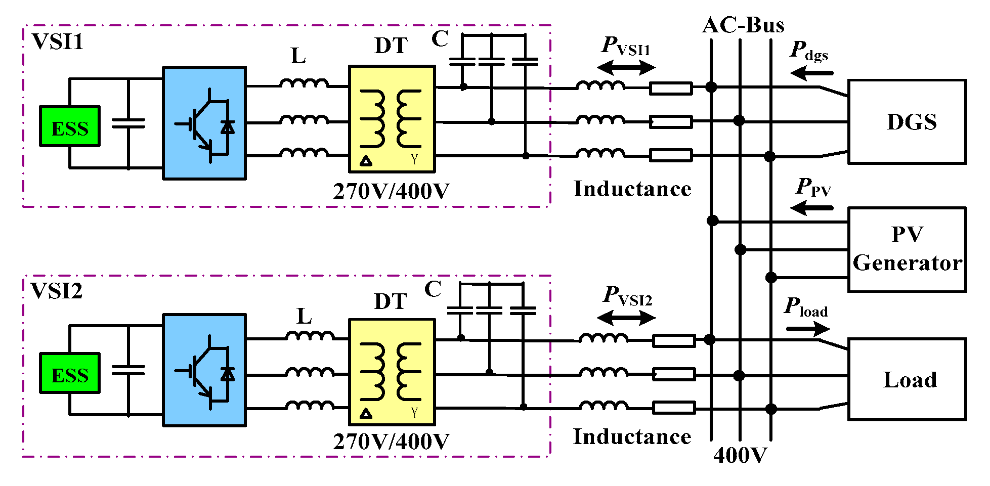
Figure 1 shows a typical system structure of an autonomous PV–battery–diesel microgrid based on a PV generator, two VSI units, and a DGS working in parallel. For each space vector pulse width modulation (SVPWM) VSI unit, the dc power is supplied by an ESS, and a fixed dc voltage is assumed in this paper to simplify the theoretic analysis. Each VSI unit is integrated to the ac-bus through a LC filter and a distribution transformer (DT). The VSI can inject power either into the ac-bus—inverter mode, or into the ESS—rectifier mode. Depending on the proportion between PV and ESS power, the microgrid operation can be characterized as a low PV penetration level and a high PV penetration level.
Based on a DGS unit and two VSI units running in parallel, the power contribution of the PV generator is relatively small, i.e., the autonomous microgrid operates with a low PV penetration. In this situation, frequency variations due to PV fluctuations would be in an appropriate limit. The active power balance in the ac-bus is given by
where
PVSI1,
PVSI2,
Pdgs,
PPV, and
Pload are the VSI units, DGS, PV generator, and load instantaneous active powers, respectively.
On the other hand, for a certain load condition, only one VSI and a DGS operating in isochronous mode will be service. Under this circumstance, the power dedication of the solar source might be comparatively high, i.e., the microgrid would run in high PV penetration. As a result, PV fluctuations would produce unacceptable frequency variations. However, the frequency variations result in rapid acceleration or deceleration of the DGS rotor, and they can be mitigated with a suitable control method. The active power balance in the ac-bus is given by
where
PVSI is the active power of the VSI in service.
As illustrated before, this paper concentrates on the situation when the autonomous microgrid is exposed to a high PV penetration. For purpose of analysis, it is assumed that the voltage amplitude of the ac-bus is regulated, and it is considered constant.
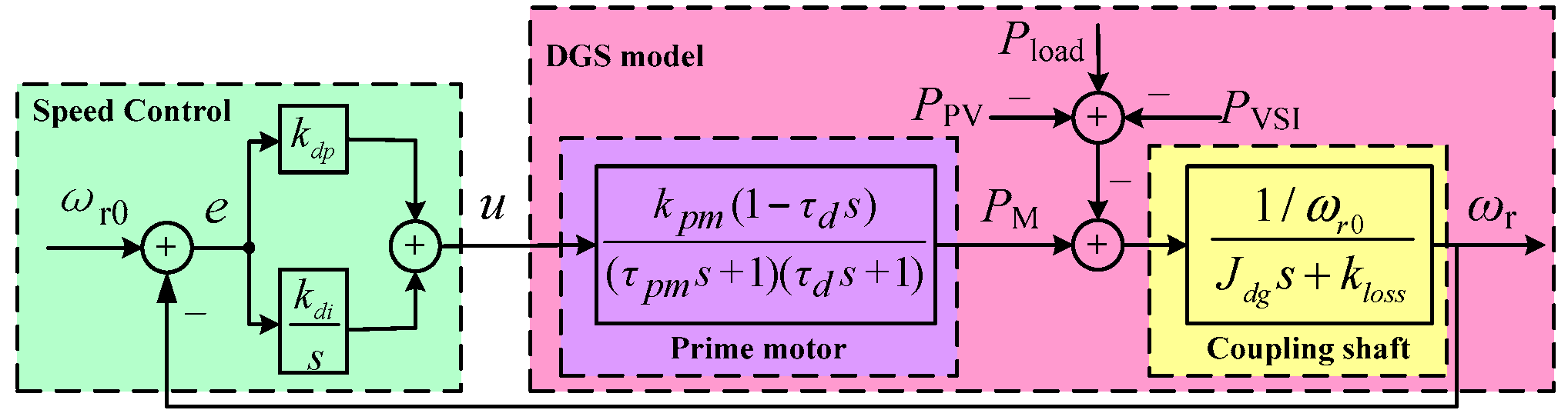
The DGS model is made up of two major components coupled by a collaborative shaft: the diesel prime mover and the SG. Due to the scope of this paper, the speed control schematic diagram of the DGS with a proportional–integrative (PI) controller is shown in
Figure 2, according to [
1].
In
Figure 2,
Jdg is the rotating inertia,
ωr is the rotor angular speed, and
kloss represents the rotational losses,
ωr0 is the synchronous speed,
PM is the mechanical power supplied by the prime motor,
kpm concentrates the gain of fuel injection system and diesel engine,
τpm is the time constant of the fuel injection system,
τd is the dead time of the diesel engine,
kdp and
kdi are the proportional and integral factors of a PI controller. The parameters of a 26 kW DGS obtained from [
25] are shown in
Table 1.
3. Impact of Virtual Synchronous Generator (VSG) on Frequency Stability
This section presents the utilization of a VSG to provide dynamic frequency control in an autonomous microgrid. Particularly, the VSG is realized with a VSI, and the method used to provide dynamic frequency support consists of simulating the damping power and the inertial response of a real SG, which are available only during a transient.
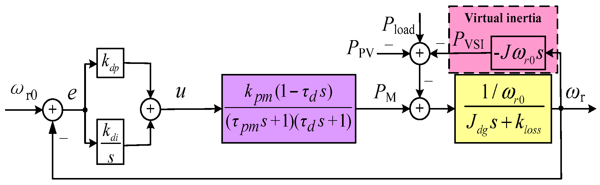
If the active power of the VSG is managed in inverse proportion to the derivative of the rotor speed, then promoting the inertial response of the DGS to variations in the power demand [
4]. Hence, the active power of the VSG is defined as
where
J is the virtual inertia. The inertial response of the VSG simulates the power that is inherently absorbed or released by a real SG as the power demand changes [
21]. When the rotor speed begins to reduce (a negative derivative), the VSG begins to inject active power into the system until the rotor speed attains its minimum (when the first derivative is zero), then the rotor speed begins to rise (a positive derivative), and then the VSG begins to absorb active power. This procedure will last until the new steady state is realized.
Figure 3 shows the block diagram for speed control with the virtual inertia control loop.
From
Figure 3, the transfer function in terms of the active powers as inputs can be obtained as follows:
where
Jeq = (
Jdg +
J) is the total inertia,
M = (
klossωr0 +
kdp −
kdiτd). On the basis of (4), the standard parameters of a second-order transient response with the virtual inertia loop can be defined as
where
ωn1 is the natural oscillation frequency,
ξ1 is the damping ratio. From the (5), it could be established that, in exchange for adding the virtual inertia, the control system becomes more oscillatory and slower as the values of
ξ1 and
ωn1 become smaller. Due to space limitations, the design of the virtual inertia is not discussed here, and more details are available in [
26].
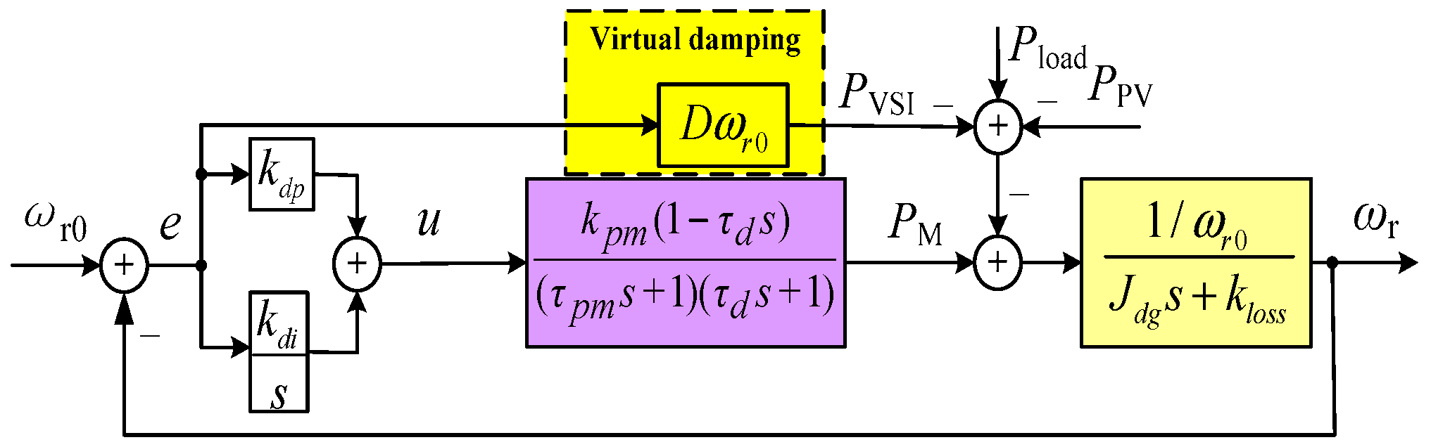
On the other hand, if the active power of the VSG is managed in proportion to the deviation of the rotor speed, then enhancing the damping power of the DGS leads to variations in the power demand. The active power of the VSG is defined as
where
D is the virtual damping of the VSG. The damping power is supplied by the virtual damper windings that help to weaken oscillations, and hence, reduce the stabilization time for a predefined tolerance band. Any deviation from the synchronous speed generates a power that tries to bring back the rotor speed to the reference [
22].
Figure 4 shows the block diagram for speed control with the virtual damping control loop.
From
Figure 4, the transfer function in terms of the active powers as inputs can be obtained as follows:
where
N = [(
kloss +
D)
ωr0 +
kdp −
kdiτd]. On the basis of (7), the standard parameters of a second-order transient response with the virtual damping loop can be defined as
where
ωn2 is the natural oscillation frequency,
ξ2 is the damping ratio. From (8), it could be concluded that more virtual damping would assist to stabilize the control system faster as the value of
ξ2 becomes bigger.
In order to evaluate the above analysis results, the control block diagrams of the simulation of an autonomous microgrid compensated with the VSG were built according to
Figure 3 and
Figure 4. The tests consist of a step increase in the power output of the PV generator,
PPV, at
t = 8 s from 0 kW to 10 kW, while the load power demand,
Pload, remains constant at 15 kW. It should be noted that the PV production is connected to the microgrid by a PV inverter which is operating as a controlled current source. Then, a step increase in the power output of the PV generator can be achieved by regulating the PV inverter in this paper. In these conditions, the microgrid will operate at a high PV penetration level of 40%. The DGS parameters used in simulations are presented in
Table 1. The suitable values of
J and
D can be determined by the (5) and (8) using the parameters listed in
Table 1. Simulations are made for speed control without virtual inertia,
J = 0, and with virtual inertia control,
J = 0.32 kg·m
2 and
J = 0.64 kg·m
2.
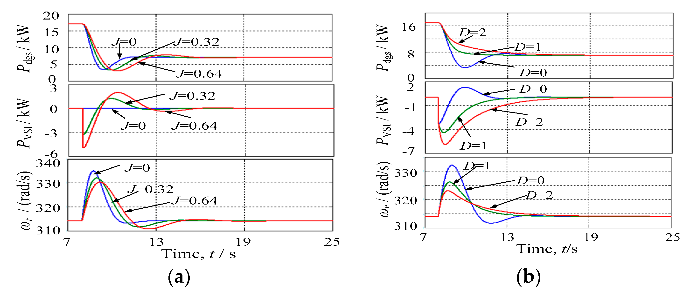
From
Figure 5a, it can be seen that the key effect of increasing virtual inertia is that the MFD decreases. However, a side effect of increasing virtual inertia is that the frequency will oscillate for a longer time. Meanwhile, increasing the virtual damping obtains a reduction in the MFD, as can be seen from
Figure 5b.
As mentioned before, the virtual inertia as well as the virtual damping are performed by means of the ESS.
Figure 5 also shows that the values of
J and
D are directly related to the expected dynamic performance and proper capacity of the ESS.
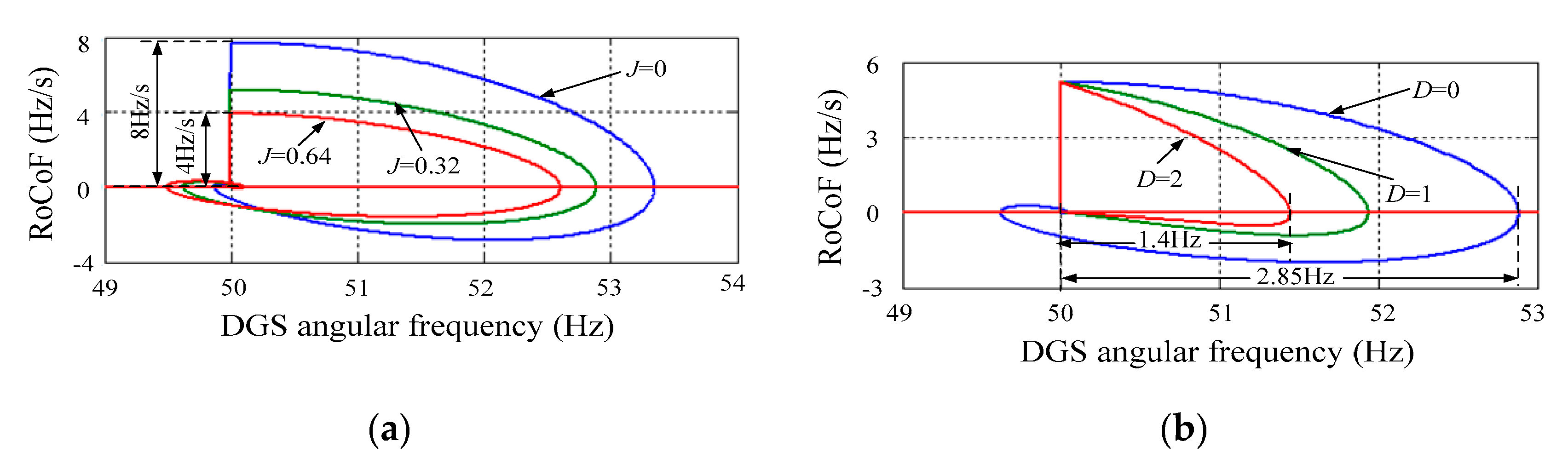
The angular frequency-acceleration trajectories of simulated DGS are shown in
Figure 6. The advantage of adding the virtual inertia is the reduction of the RoCoF due to a power disturbance. For
J = 0.64 kg·m
2, the maximum RoCoF is reduced from 8 Hz/s to 4 Hz/s, as can be seen from
Figure 6a. From
Figure 6b, it can be seen that the advantages of increasing the virtual damping are the attenuation of the amplitude of the oscillations of the frequency and the reduction of the MFD. For
D = 2, the MFD is reduced from 2.85 Hz to 1.4 Hz.
It is important to point out that, the variations of loads mainly result in the oscillations of the frequency. As a result, the changes of the latter lag behind the changes of the former. Since the inertial response as well as the damping power of the VSG are realized by measuring the variations of the frequency, thus, the dynamic frequency support provided by them is also lagging behind. In this regard, alternative approaches to provide a dynamic power response that can be synchronized with the variations of loads or even be ahead of the variations of loads.
4. Proposed VSG and Its Performance Evaluation
Considering that the first frequency oscillation is the most serious one in terms of maintaining the system frequency stability, an improved VSG based on the differential feedforward of the DGS output current is proposed to further decrease the MFD and the RoCoF. Note that the DGS output power can be approximately equal to its mechanical power under the condition of neglecting the mechanical loss and the iron loss. As a result, the differential of the DGS output current can be replaced by the differential of its mechanical power, assuming that the voltage amplitude on the ac-bus is fixed.
In this case, the active power of the VSG based on the differential feedforward of the DGS output current is defined as
where
kdf is the differential feedforward gain, and
τ is the filtering time gain of the low-pass filter (LPF). The active power is typically calculated from the time derivative of the DGS mechanical power that can expand the noise that is usually contained in this power. Hence, a LPF is applied to prevent the excessive noise from polluting the system.
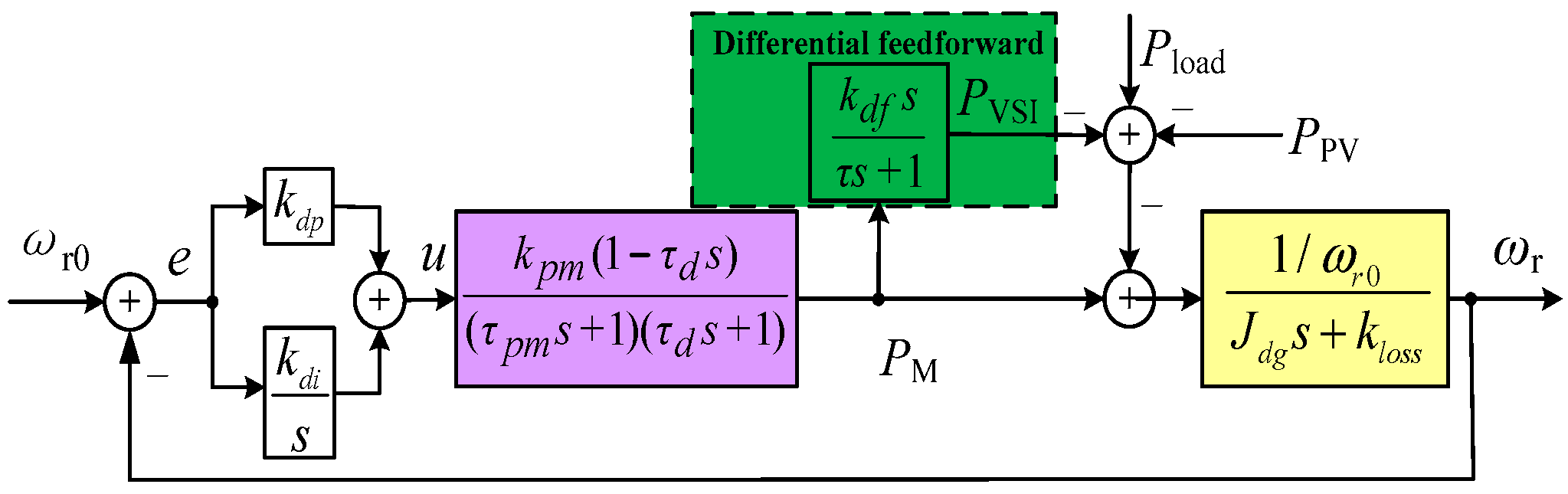
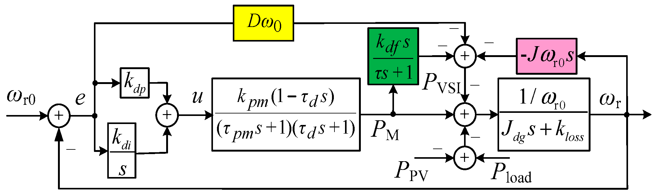
Figure 7 is the block diagram for speed control with the differential feedforward of the DGS output current control loop.
From
Figure 7, the transfer function in terms of the active powers as inputs can be obtained as follows:
where
Using (10) and (11), the trajectory of the three eigenvalues (
λ1,
λ2,
λ3) can be obtained.
Figure 8a shows the trajectory of these eigenvalues as a function of the differential feedforward gain
kdf. It can be seen that as
kdf is increased, conjugate eigenvalues
λ1 and
λ2 move towards the real axis, making the system less oscillatory. Eigenvalue
λ3 moves towards the stable region, which makes the system evolve from a third-order system to an approximate second-order system. Meanwhile,
Figure 8b shows the trajectory of these eigenvalues as a function of the filter time gain
τ. It can be seen that as
τ is increased, conjugate eigenvalues
λ1 and
λ2 move towards the real axis, making the system less oscillatory. Eigenvalue
λ3 moves towards the unstable region, which makes the system evolve from a second-order system to an approximate third-order system.
Figure 8a,b have been obtained with the DGS parameters given in
Table 1.
It is to be noted that a LPF with high cut-off frequency is required to enhance the dynamic response of the VSG, whereas a large filter time gain is required to obtain good attenuation of high frequency distortion components in the calculated active power and to increase the system damping. For this reason, and to operate without the distortion components, it is necessary to use larger τ values, like τ = 0.3 s, or τ = 0.5 s, but in exchange for longer dynamic reactions.
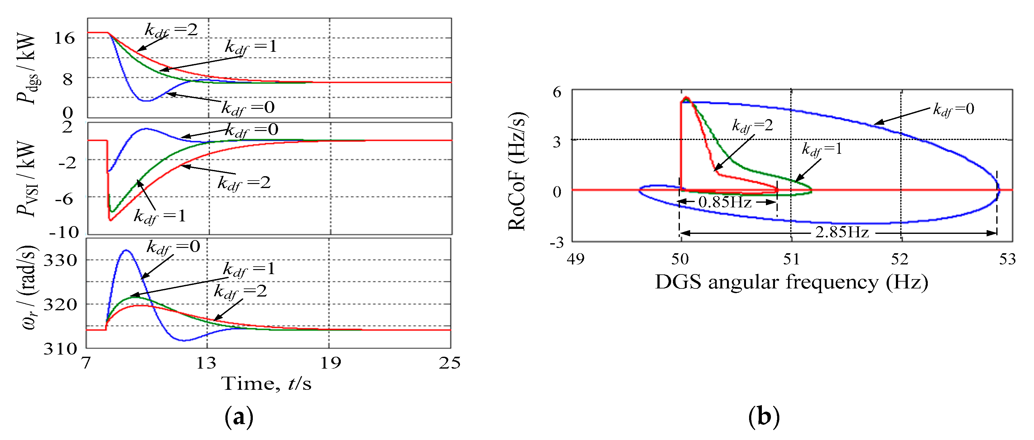
Based on the above analysis, simulations are made for speed control without differential feedforward,
kdf = 0, and with differential feedforward control,
kdf = 1 and
kdf = 2. From
Figure 9a, it can be seen that adding the differential feedforward gain produces a reduction in the MFD. Adding differential feedforward gain mitigates the MFD and the RoCoF effectively, due to a power disturbance. For
kdf = 2, the MFD is reduced from 2.85 Hz to 0.85 Hz, and the RoCoF is decreased quickly, as can be seen from
Figure 9b.
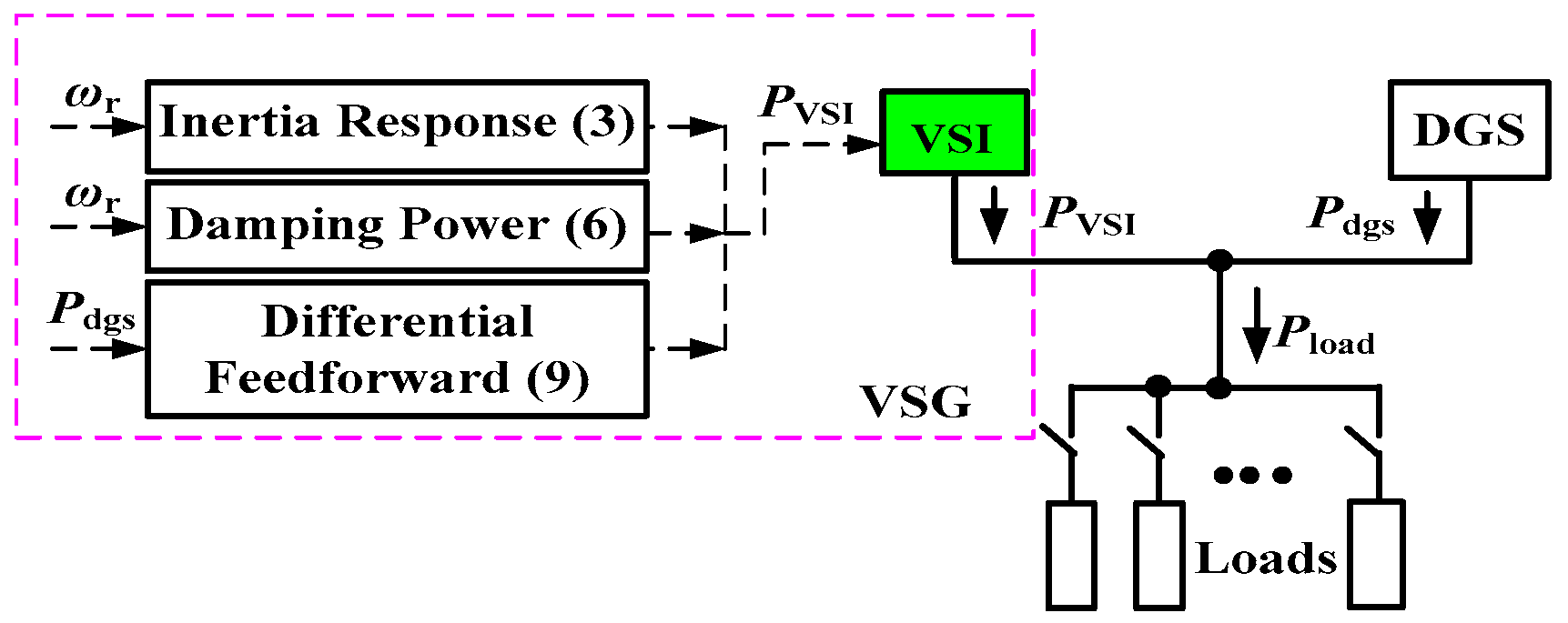
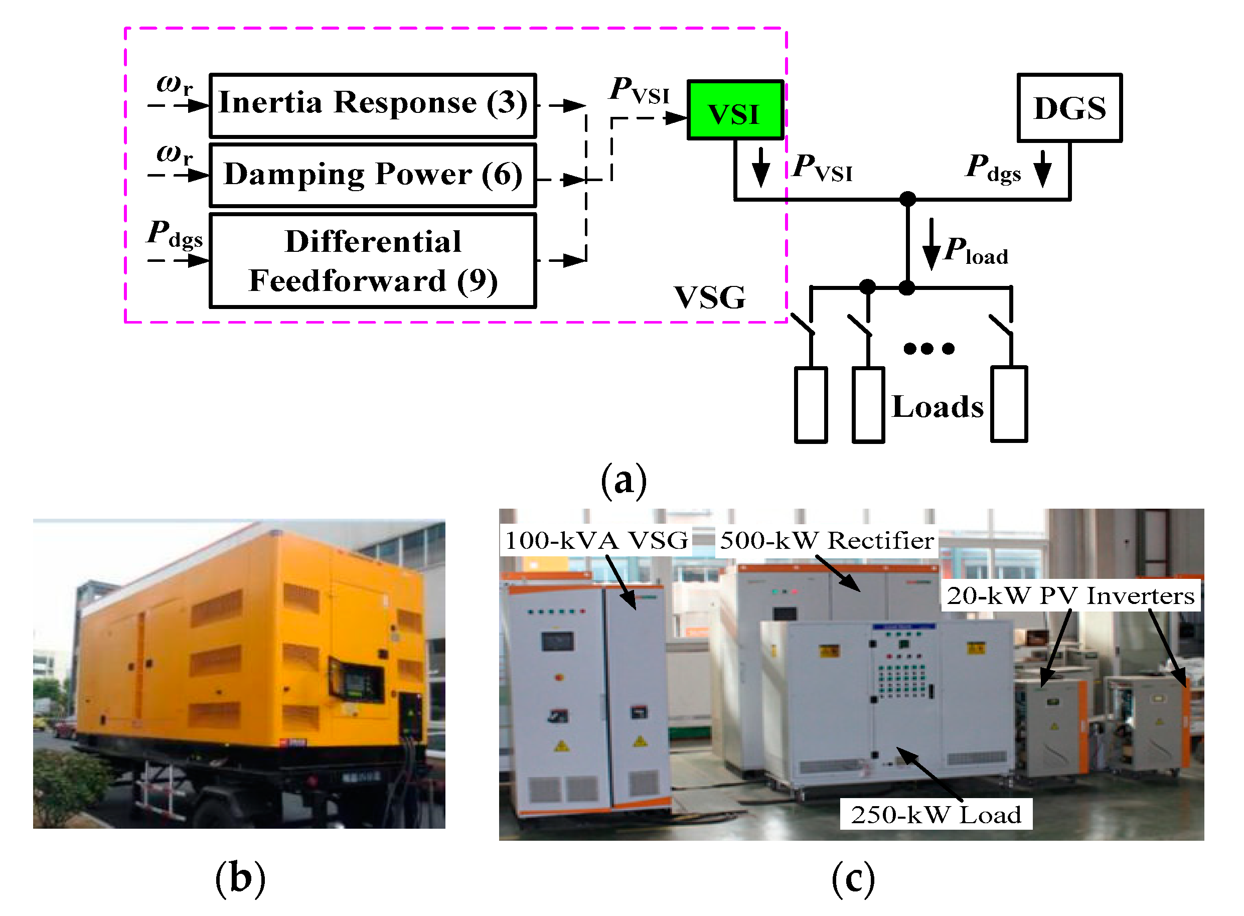
The proposed control method for the DGS is implemented as shown in
Figure 10. This control scheme can provide virtual inertia, virtual damping, and differential feedforward control for the DGS to support dynamic frequency control.
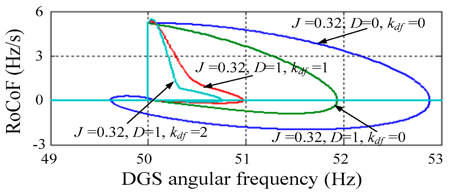
With
Figure 10, the angular frequency-acceleration trajectories of simulated DGS are shown in
Figure 11. It is obvious that the MFD and the RoCoF are mitigated more effectively for
J = 0.32 kg·m
2,
D = 1,
kdf = 2 than for
J = 0.32 kg·m
2,
D = 1,
kdf = 1, or for
J = 0.32 kg·m
2,
D = 1,
kdf = 0, or for
J = 0.32 kg·m
2,
D = 0,
kdf = 0. It implies that the proposed VSG with the differential feedforward control loop is more effective in enhancing the system frequency stability than the VSG without the differential feedforward control loop.
5. Simulation and Experimental Results
The proposed VSG control strategy for the DGS to support dynamic frequency control is confirmed through Matlab/Simulink (R2011b, MathWorks, Natick, MA. USA), and experimentally on an autonomous microgrid.
Figure 12 describes the schematic of the simulation and experiment of the microgrid consisted of a 100 kVA VSG and a 400 kW DGS for a load step of 100 kW at
t = 3 s. The system parameters of the simulation, as well as the experiments, are almost the same, and are enumerated in
Table 2.
A. Simulation verification
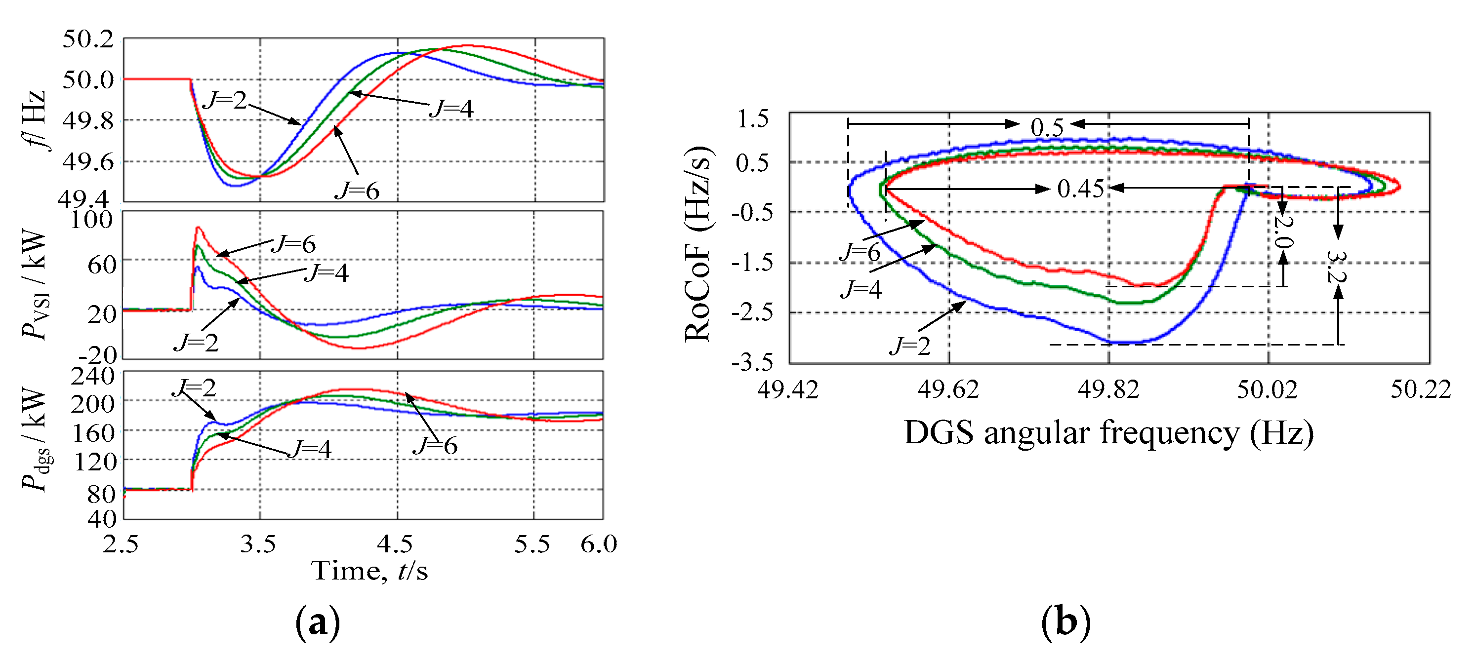
(1) Virtual inertia: From
Figure 13a, it can be seen that a side effect of increasing virtual inertia is that the system frequency will oscillate for a longer time. However, increasing virtual inertia reduces the MFD and the RoCoF effectively due to a power disturbance. For
J = 6 kg·m
2, the MFD is decreased from 0.5 Hz to 0.45 Hz and the maximum RoCoF is decreased from 3.2 Hz/s to 2 Hz/s, as can be seen from
Figure 13b.
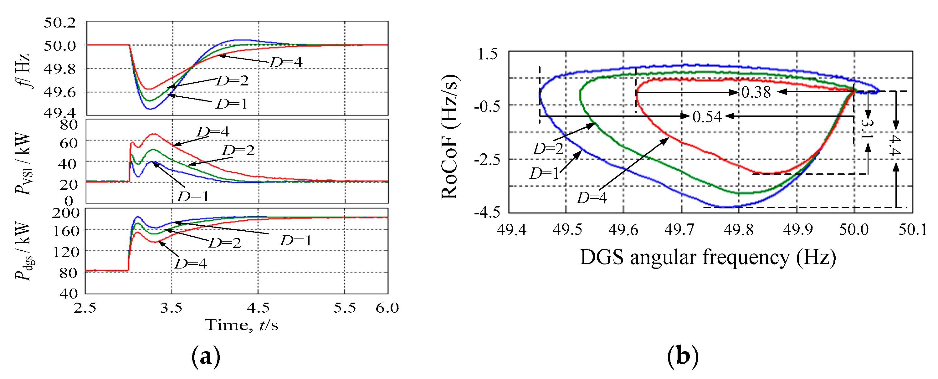
(2) Virtual damping: The same tests are conducted for the VSG with the added virtual damping to support dynamic frequency control on an active power transient.
Figure 14a displays the simulation results for the alterations of the system frequency, the output active powers of the VSG, and the DGS. It is observed that the advantages of adding virtual damping to the system are the attenuation of the amplitude of the oscillations of the frequency and the reduction of the MFD.
From
Figure 14b, it can be seen that the curve “
D = 4” illustrates the RoCoF and the MFD with respect to the rated value that situates inside the other two curves. It explains that increasing the virtual damping produces reductions in the MFD and the RoCoF. For
D = 4, the MFD is reduced from 0.54 Hz to 0.38 Hz, and the maximum RoCoF is reduced from 4.4 Hz/s to 3.1 Hz/s.
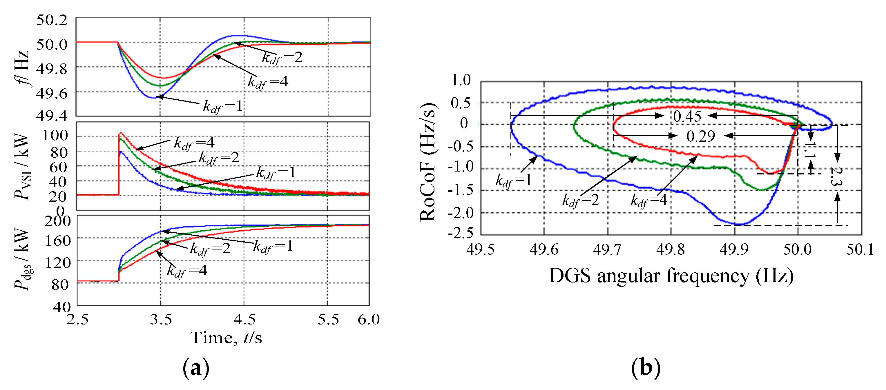
(3) Differential feedforward:
Figure 15a displays the simulation results for the alterations of the system frequency, the output active powers of the VSG, and the DGS. It is observed that the advantages of adding the differential feedforward gain are the attenuation of the amplitude of the oscillations of the frequency and the reduction of the MFD. On the other hand, the curve “
kdf = 4” illustrates the RoCoF and the MFD with respect to the rated value that situates inside the other two curves. It explains that increasing the differential feedforward gain mitigates both the MFD and the RoCoF effectively. For
kdf = 4, the MFD is reduced from 0.45 Hz to 0.29 Hz, and the maximum RoCoF is reduced from 2.3 Hz/s to 1.1 Hz/s, as can be seen from
Figure 15b.
B. Experimental verification
Experiments are also carried out on an autonomous microgrid consisting of a 100 kVA VSG and a 400 kW DGS for a load step of 100 kW to verify the proposed VSG-based dynamic frequency support scheme. In the experiments, a three-phase programmable rectifier is used to represent the ESS, and the three-phase VSG system is controlled by a TMS320F28335 DSP (TMS320C28x, Texas Instruments, Dallas, TX, USA), which implements the proposed control strategies, as described in the previous sections. The VSG unit consists of a three-phase IGBT full bridge with a switching frequency of 5 kHz and an LC output filter, using the parameters listed in
Table 2. The experimental platform of the autonomous microgrid is shown in
Figure 16. The transitory regime is created by switching a resistive load of 100 kW on at certain time intervals in the experiment as shown in
Figure 16a.
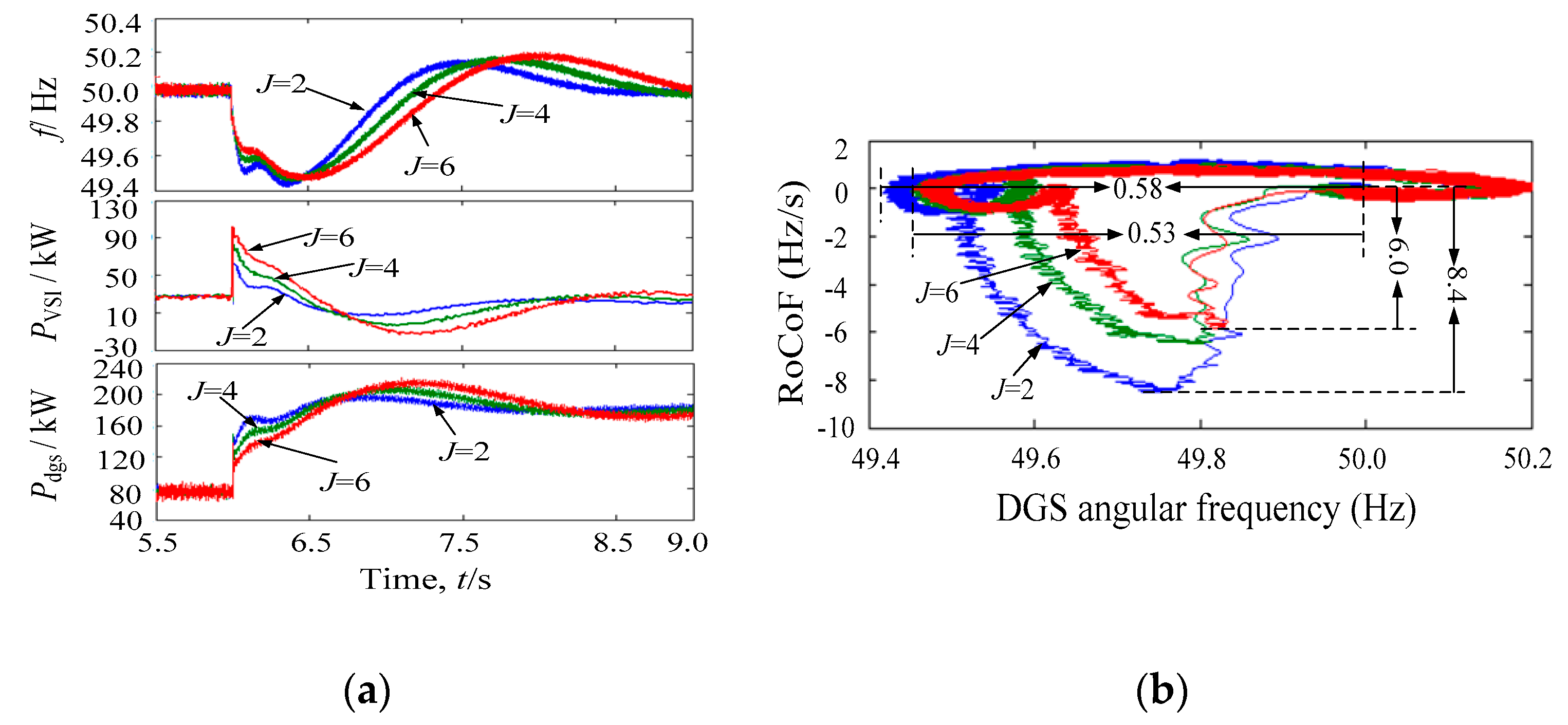
(1) Virtual inertia: The performance of increasing virtual inertia is shown in
Figure 17a, where it can be found that the system frequency oscillates for a longer time. When the dynamic frequency support is complemented by the virtual inertia control loop (with
J = 2 kg·m
2,
J = 4 kg·m
2, and
J = 6 kg·m
2), the VSG outputs dynamic active power. As a result, both the MFD and the RoCoF are decreased, as shown in
Figure 17b. For
J = 6 kg·m
2, the MFD is decreased from 0.58 Hz to 0.53 Hz, and the maximum RoCoF is decreased from 8.4 Hz/s to 6.0 Hz/s.
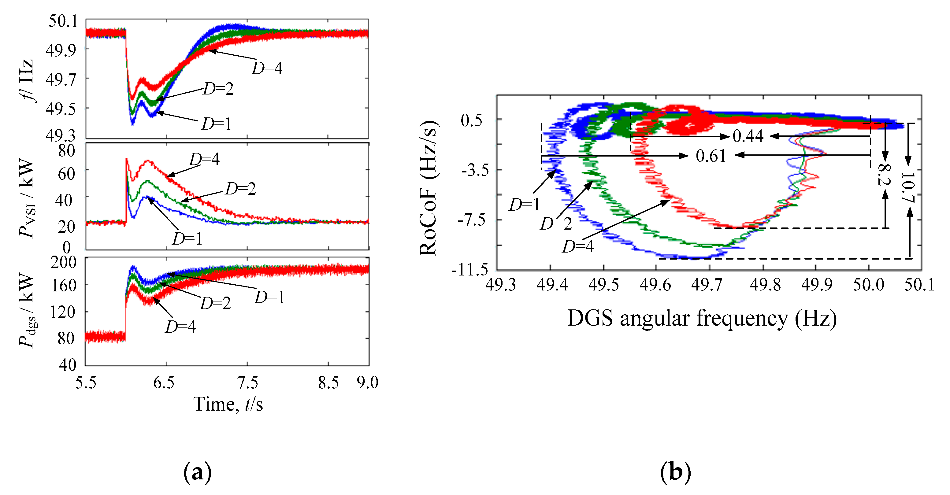
(2) Virtual damping:
Figure 18a displays the experimental results for the alterations of the system frequency, the output active powers of the VSG, and the DGS. It is observed that the advantages of increasing virtual damping are the attenuation of the amplitude of the oscillations of the frequency and the reduction of the MFD.
When the dynamic frequency support is complemented by the virtual damping control loop (with
D = 1,
D = 2, and
D = 4), the VSG outputs dynamic active power. As a result, both the MFD and the RoCoF are decreased, as shown in
Figure 18b. For
D = 4, the MFD is decreased from 0.61 Hz to 0.44 Hz, and the maximum RoCoF is decreased from 10.7 Hz/s to 8.2 Hz/s.
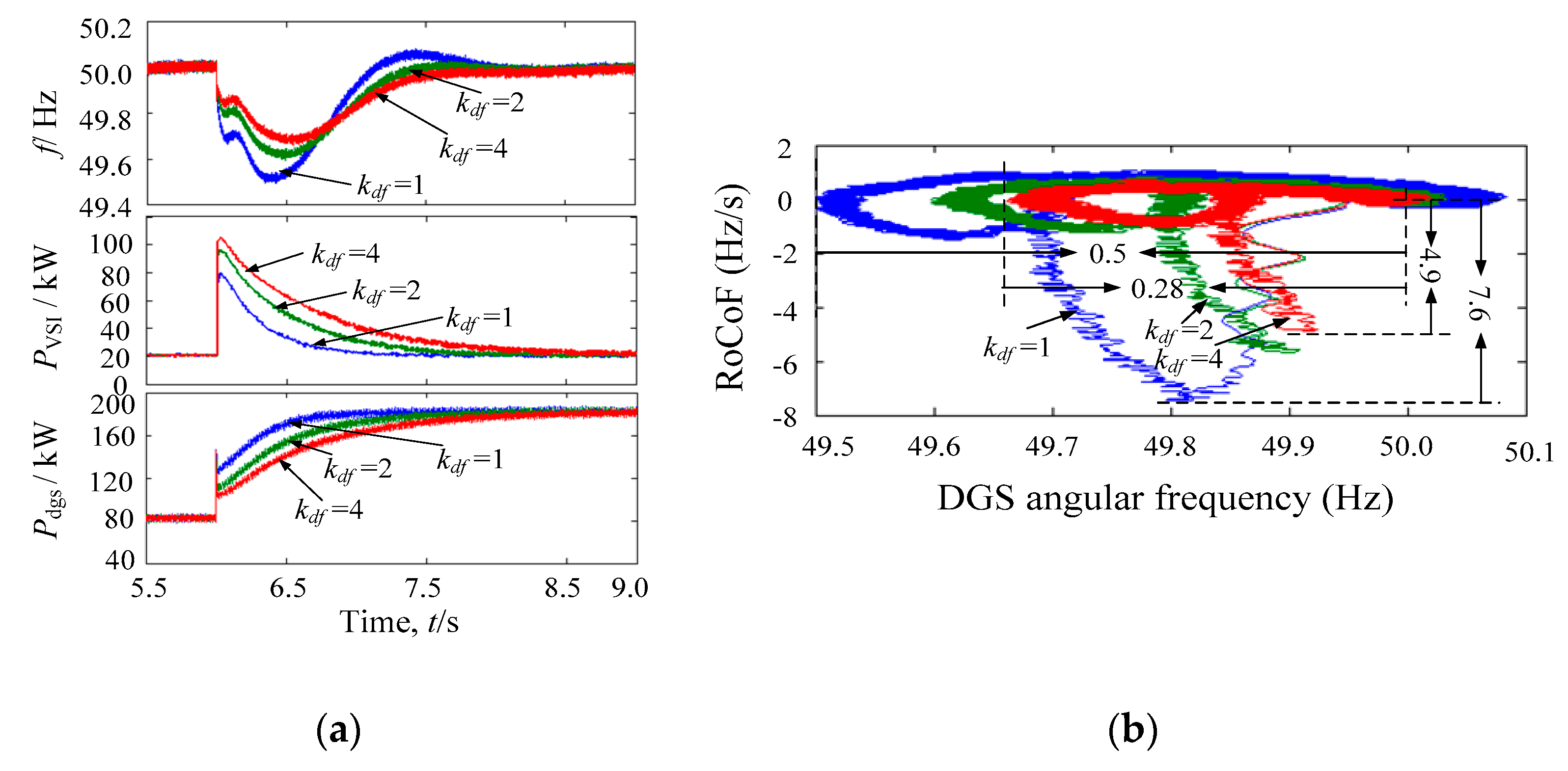
(3) Differential feedforward:
Figure 19a displays the experimental results for the alterations of the system frequency, the output active powers of the VSG, and the DGS. It is observed that the advantages of adding the differential feedforward gain are the attenuation of the amplitude of the oscillations of the frequency and the reduction of the MFD.
On the other hand, when the dynamic frequency support is complemented by the differential feedforward control loop (with
kdf = 1,
kdf = 2, and
kdf = 4), the VSG outputs dynamic active power. As a result, both the MFD and the RoCoF are decreased, as shown in
Figure 19b. For
kdf = 4, the MFD is reduced from 0.5 Hz to 0.28 Hz, and the maximum RoCoF is reduced from 7.6 Hz/s to 4.9 Hz/s.
C. Summary
Table 3 summarizes the experimental results. Absolute error is calculated only between the maximum value and the minimum value as (
xmax −
xmin). To compare the performances of the virtual inertia, the virtual damping, and the differential feedforward, two indexes that give a survey of how much energy is applied from the ESS to decrease the MFD and the RoCoF are defined as
where
EAE is the absolute error between the delivered energy
Ede and the recovered energy
Ere of the VSG,
MFDAE is the absolute error of the MFD, and
RoCoFAE is the absolute error of the RoCoF.
Table 4 displays the calculated results of
Iperf and
Iperdf for the VSG for the different experimental scenarios. It can be found that the virtual inertia control is more efficient in reducing the RoCoF than the other control methods, but it uses more energy in reducing the MFD. On the other hand, it can be found that the values calculated for the VSG with the differential feedforward control are continuously smaller than the values calculated for the VSG with the virtual damping control. This illustrates that the differential feedforward control uses less energy in reducing the MFD than the virtual damping control, using approximately 70% of the delivered energy. In addition, the differential feedforward control uses less energy in reducing the RoCoF than the virtual damping control, using approximately 84% of the delivered energy, i.e., is more effective in supporting dynamic frequency control.
On the other hand, with the differential feedforward control, the system presented is more effective in reducing the MFD than the virtual inertia control, using approximately 54% of the delivered energy, however, it uses only 45% of energy in reducing the RoCoF used by the virtual inertia control.
6. Conclusions
The dynamic frequency support control for the autonomous PV–diesel hybrid microgrids with the ESS based on VSG is investigated in this paper. The performances of the virtual inertia, the virtual damping, as well as the differential feedforward are evaluated by comparing their reductions in the MFD and the RoCoF for the simulation and experimental scenarios. For experimental cases, the virtual inertia control is more efficient in reducing the RoCoF than the other control methods, but uses more energy in reducing the MFD. Meanwhile, a side effect of increasing virtual inertia is that the system becomes more oscillatory and slower. On the other hand, the differential feedforward control achieves the same performance to that of the virtual damping control while reducing the MFD and the RoCoF. Moreover, in all the experimental scenarios, the differential feedforward control uses less energy in reducing the MFD and the RoCoF than the virtual damping control, i.e., is more effective in supporting dynamic frequency control.
Finally, it was also found that, depending on the type of load variation, the operation of the proposed differential feedforward control may lead to a greater charge/discharge of the ESS when compared to the virtual inertia control. This suggests that further work is required in order to include the state of health and the state of charge of the ESS for the differential feedforward control. Also, a stability analysis is required in order to know the admissible values for kdf.


